EP2826683A1 - Schienenbremssystem für Schienenfahrzeug, und Bremsverfahren eines Schienenfahrzeugs, das ein solches System umfasst - Google Patents
Schienenbremssystem für Schienenfahrzeug, und Bremsverfahren eines Schienenfahrzeugs, das ein solches System umfasst Download PDFInfo
- Publication number
- EP2826683A1 EP2826683A1 EP14176400.1A EP14176400A EP2826683A1 EP 2826683 A1 EP2826683 A1 EP 2826683A1 EP 14176400 A EP14176400 A EP 14176400A EP 2826683 A1 EP2826683 A1 EP 2826683A1
- Authority
- EP
- European Patent Office
- Prior art keywords
- brake
- pressure chamber
- service
- service brake
- parking brake
- Prior art date
- Legal status (The legal status is an assumption and is not a legal conclusion. Google has not performed a legal analysis and makes no representation as to the accuracy of the status listed.)
- Granted
Links
- 238000000034 method Methods 0.000 title claims description 7
- 230000000903 blocking effect Effects 0.000 claims abstract description 5
- 239000012530 fluid Substances 0.000 claims description 60
- 238000004891 communication Methods 0.000 claims description 59
- 239000003795 chemical substances by application Substances 0.000 claims description 47
- 238000013022 venting Methods 0.000 claims description 5
- 238000001514 detection method Methods 0.000 claims description 2
- 230000001960 triggered effect Effects 0.000 claims description 2
- 208000031968 Cadaver Diseases 0.000 description 12
- 235000021183 entrée Nutrition 0.000 description 8
- 238000012550 audit Methods 0.000 description 6
- 238000006073 displacement reaction Methods 0.000 description 4
- 229940082150 encore Drugs 0.000 description 3
- 239000012528 membrane Substances 0.000 description 2
- 240000008042 Zea mays Species 0.000 description 1
- 230000000295 complement effect Effects 0.000 description 1
- 238000007599 discharging Methods 0.000 description 1
- 230000000694 effects Effects 0.000 description 1
- 238000004519 manufacturing process Methods 0.000 description 1
- 238000007789 sealing Methods 0.000 description 1
- 230000007704 transition Effects 0.000 description 1
- 230000002747 voluntary effect Effects 0.000 description 1
Images


Classifications
-
- B—PERFORMING OPERATIONS; TRANSPORTING
- B60—VEHICLES IN GENERAL
- B60T—VEHICLE BRAKE CONTROL SYSTEMS OR PARTS THEREOF; BRAKE CONTROL SYSTEMS OR PARTS THEREOF, IN GENERAL; ARRANGEMENT OF BRAKING ELEMENTS ON VEHICLES IN GENERAL; PORTABLE DEVICES FOR PREVENTING UNWANTED MOVEMENT OF VEHICLES; VEHICLE MODIFICATIONS TO FACILITATE COOLING OF BRAKES
- B60T17/00—Component parts, details, or accessories of power brake systems not covered by groups B60T8/00, B60T13/00 or B60T15/00, or presenting other characteristic features
- B60T17/08—Brake cylinders other than ultimate actuators
- B60T17/16—Locking of brake cylinders
-
- B—PERFORMING OPERATIONS; TRANSPORTING
- B60—VEHICLES IN GENERAL
- B60T—VEHICLE BRAKE CONTROL SYSTEMS OR PARTS THEREOF; BRAKE CONTROL SYSTEMS OR PARTS THEREOF, IN GENERAL; ARRANGEMENT OF BRAKING ELEMENTS ON VEHICLES IN GENERAL; PORTABLE DEVICES FOR PREVENTING UNWANTED MOVEMENT OF VEHICLES; VEHICLE MODIFICATIONS TO FACILITATE COOLING OF BRAKES
- B60T13/00—Transmitting braking action from initiating means to ultimate brake actuator with power assistance or drive; Brake systems incorporating such transmitting means, e.g. air-pressure brake systems
- B60T13/10—Transmitting braking action from initiating means to ultimate brake actuator with power assistance or drive; Brake systems incorporating such transmitting means, e.g. air-pressure brake systems with fluid assistance, drive, or release
- B60T13/24—Transmitting braking action from initiating means to ultimate brake actuator with power assistance or drive; Brake systems incorporating such transmitting means, e.g. air-pressure brake systems with fluid assistance, drive, or release the fluid being gaseous
- B60T13/26—Compressed-air systems
- B60T13/36—Compressed-air systems direct, i.e. brakes applied directly by compressed air
- B60T13/365—Compressed-air systems direct, i.e. brakes applied directly by compressed air for railway vehicles
-
- B—PERFORMING OPERATIONS; TRANSPORTING
- B60—VEHICLES IN GENERAL
- B60T—VEHICLE BRAKE CONTROL SYSTEMS OR PARTS THEREOF; BRAKE CONTROL SYSTEMS OR PARTS THEREOF, IN GENERAL; ARRANGEMENT OF BRAKING ELEMENTS ON VEHICLES IN GENERAL; PORTABLE DEVICES FOR PREVENTING UNWANTED MOVEMENT OF VEHICLES; VEHICLE MODIFICATIONS TO FACILITATE COOLING OF BRAKES
- B60T13/00—Transmitting braking action from initiating means to ultimate brake actuator with power assistance or drive; Brake systems incorporating such transmitting means, e.g. air-pressure brake systems
- B60T13/10—Transmitting braking action from initiating means to ultimate brake actuator with power assistance or drive; Brake systems incorporating such transmitting means, e.g. air-pressure brake systems with fluid assistance, drive, or release
- B60T13/66—Electrical control in fluid-pressure brake systems
- B60T13/665—Electrical control in fluid-pressure brake systems the systems being specially adapted for transferring two or more command signals, e.g. railway systems
-
- B—PERFORMING OPERATIONS; TRANSPORTING
- B61—RAILWAYS
- B61H—BRAKES OR OTHER RETARDING DEVICES SPECIALLY ADAPTED FOR RAIL VEHICLES; ARRANGEMENT OR DISPOSITION THEREOF IN RAIL VEHICLES
- B61H13/00—Actuating rail vehicle brakes
- B61H13/02—Hand or other personal actuation
- B61H13/04—Hand or other personal actuation by mechanisms incorporating toothed gearing
-
- F—MECHANICAL ENGINEERING; LIGHTING; HEATING; WEAPONS; BLASTING
- F16—ENGINEERING ELEMENTS AND UNITS; GENERAL MEASURES FOR PRODUCING AND MAINTAINING EFFECTIVE FUNCTIONING OF MACHINES OR INSTALLATIONS; THERMAL INSULATION IN GENERAL
- F16D—COUPLINGS FOR TRANSMITTING ROTATION; CLUTCHES; BRAKES
- F16D55/00—Brakes with substantially-radial braking surfaces pressed together in axial direction, e.g. disc brakes
- F16D55/02—Brakes with substantially-radial braking surfaces pressed together in axial direction, e.g. disc brakes with axially-movable discs or pads pressed against axially-located rotating members
- F16D55/22—Brakes with substantially-radial braking surfaces pressed together in axial direction, e.g. disc brakes with axially-movable discs or pads pressed against axially-located rotating members by clamping an axially-located rotating disc between movable braking members, e.g. movable brake discs or brake pads
- F16D55/224—Brakes with substantially-radial braking surfaces pressed together in axial direction, e.g. disc brakes with axially-movable discs or pads pressed against axially-located rotating members by clamping an axially-located rotating disc between movable braking members, e.g. movable brake discs or brake pads with a common actuating member for the braking members
- F16D55/2245—Brakes with substantially-radial braking surfaces pressed together in axial direction, e.g. disc brakes with axially-movable discs or pads pressed against axially-located rotating members by clamping an axially-located rotating disc between movable braking members, e.g. movable brake discs or brake pads with a common actuating member for the braking members in which the common actuating member acts on two levers carrying the braking members, e.g. tong-type brakes
-
- F—MECHANICAL ENGINEERING; LIGHTING; HEATING; WEAPONS; BLASTING
- F16—ENGINEERING ELEMENTS AND UNITS; GENERAL MEASURES FOR PRODUCING AND MAINTAINING EFFECTIVE FUNCTIONING OF MACHINES OR INSTALLATIONS; THERMAL INSULATION IN GENERAL
- F16D—COUPLINGS FOR TRANSMITTING ROTATION; CLUTCHES; BRAKES
- F16D65/00—Parts or details
- F16D65/14—Actuating mechanisms for brakes; Means for initiating operation at a predetermined position
- F16D65/16—Actuating mechanisms for brakes; Means for initiating operation at a predetermined position arranged in or on the brake
- F16D65/18—Actuating mechanisms for brakes; Means for initiating operation at a predetermined position arranged in or on the brake adapted for drawing members together, e.g. for disc brakes
-
- F—MECHANICAL ENGINEERING; LIGHTING; HEATING; WEAPONS; BLASTING
- F16—ENGINEERING ELEMENTS AND UNITS; GENERAL MEASURES FOR PRODUCING AND MAINTAINING EFFECTIVE FUNCTIONING OF MACHINES OR INSTALLATIONS; THERMAL INSULATION IN GENERAL
- F16D—COUPLINGS FOR TRANSMITTING ROTATION; CLUTCHES; BRAKES
- F16D2125/00—Components of actuators
- F16D2125/18—Mechanical mechanisms
- F16D2125/58—Mechanical mechanisms transmitting linear movement
- F16D2125/66—Wedges
-
- F—MECHANICAL ENGINEERING; LIGHTING; HEATING; WEAPONS; BLASTING
- F16—ENGINEERING ELEMENTS AND UNITS; GENERAL MEASURES FOR PRODUCING AND MAINTAINING EFFECTIVE FUNCTIONING OF MACHINES OR INSTALLATIONS; THERMAL INSULATION IN GENERAL
- F16D—COUPLINGS FOR TRANSMITTING ROTATION; CLUTCHES; BRAKES
- F16D2127/00—Auxiliary mechanisms
- F16D2127/02—Release mechanisms
Definitions
- the invention relates to the field of braking of railway vehicles.
- It relates more particularly to railway braking systems for railway vehicles provided with a service brake and a parking brake configured to act on a braking linkage.
- Railway vehicles are generally equipped with service brake cylinders having a piston movable under the effect of a fluid under pressure, the movement of this piston causing a braking action such as the clamping of a brake disc between two linings , or the direct pressure of a soleplate against a wheel of the vehicle.
- These brake cylinders also generally comprise a parking or emergency actuator which is activated in the event of pressure loss of the pressurized fluid and / or in case of voluntary emptying or leakage of the pneumatic system.
- This actuator also called parking brake, provides braking through the force of a spring replacing the force of the fluid. Once this parking brake is activated, the brake remains permanently tight.
- the brake cylinder also includes a pressure chamber defined by the piston and the body and which is connected by a conduit to a source of pneumatic pressure medium to put the piston into a service braking position.
- the parking brake has a body which is distinct from the body of the brake cylinder.
- the body of the parking brake has an opening opposite the piston of the service brake cylinder, which opening slidably receives a thrust sleeve fitting in this opening in a sealed manner.
- the parking brake also comprises a piston movably mounted in a cylinder integral with the body and delimiting with the body a parking brake pressure chamber.
- This parking brake pressure chamber is connected to another source of pneumatic pressure medium via a conduit.
- the piston has in its center an orifice through which the thrust sleeve passes.
- the parking brake further comprises springs which constantly urge the piston of the parking brake to a so-called low position where the parking brake is considered to be in a working configuration.
- the pressure chamber of the parking brake (previously filled with the pneumatic pressure agent) is drained and the brake springs of parking then act on the piston of the parking brake, which drives the sleeve until the latter bears against the piston of the service brake cylinder.
- the pressure chamber of the service brake cylinder can then be drained since the parking brake is actuated.
- the force applied by the parking brake on the service brake piston is directly a function of the force developed by the springs. This force is of course a function of the stiffness and elongation of these springs.
- the invention relates to a braking system for a railway vehicle, having improved performance compared to the prior art braking systems mentioned above, while being simple, convenient and economical.
- the braking piston is immobilized in the service braking position by the parking brake and in particular by its locking device.
- the brake piston can be immobilized in any position, which position is related to the stroke that the piston has traveled and this stroke depends on the force applied during the service braking phase.
- immobilize means that the force applied by the brake piston on the braking linkage in the working configuration of the parking brake does not decrease, or almost no.
- the invention in particular to the configuration of the braking piston and the parking brake, it eliminates in particular the springs of the known braking systems described above which allow to apply the parking brake force on the braking linkage through the piston of the service brake cylinder.
- the braking system according to the invention is more compact than the braking systems of the aforementioned prior art, and also lighter .
- the braking linkage advantageously has deformable arms whose elasticity can be substituted for the springs of known braking systems described above.
- the configuration of the parking brake is chosen such that the force applied directly by the locking device to immobilize the brake piston is not greater than the force applied by the springs on the piston of the braking systems. the aforementioned prior art; whereas the force applied to the braking linkage when the parking brake of the system according to the invention is in working configuration is at least equal to or greater than that provided by the braking systems of the aforementioned prior art.
- the braking system according to the invention also makes it possible to momentarily supply the service brake pressure chamber with the second source of pneumatic pressure medium in order to increase the braking force applied to the brake. braking linkage by the service brake piston.
- the second source of pneumatic pressure agent initially feeds the parking brake pressure chamber.
- the system according to the invention thus makes it possible to obtain parking brake and parking brake forces greater than those obtained with the above-mentioned braking systems of the prior art, in a simple, convenient and economical manner.
- the method according to the invention is particularly simple and convenient to implement.
- said step of controlling the emptying of said parking brake pressure chamber is triggered following the detection of a predetermined pressure threshold and / or said step of controlling the emptying of said service brake pressure chamber is effected by allowing said service brake pressure chamber to leak.
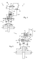
- the figure 1 schematically represents a rail braking system 1 for a rail vehicle brake lining or soles.
- the rail braking system 1 comprises a body 2 forming here a cylinder of both service brake 6 and parking brake 7, a pneumatic pipe routing network 3 connected to the body 2, a wheelhouse brake 4 mechanically connected to the body 2 and a brake 5 lining on which the brake linkage 4 is configured to act.
- the body 2 here has the shape of a generally closed envelope.
- the service brake 6 comprises a service brake piston 8 movable relative to the body 2 in a first axial direction, a thrust rod 9 also movable relative to the body 2 in a second axial direction perpendicular to the first axial direction.
- the braking piston 8 delimits with the body 2 a service brake pressure chamber 13.
- the braking piston 8 has two sides respectively a first side 17 configured to act on the braking linkage 4 via the push rod 9 and a second side 18 opposite the first side 17 and facing the pressure chamber of service brake 13.
- the service brake 6 further comprises a notched rod 21 fixed on the second side 18 of the braking piston 8. This notched rod 21 extends longitudinally along the first axial direction.
- the braking piston 8 is configured to move in the body 2 while maintaining the service brake pressure chamber 13 relatively tight thanks to a membrane 14 disposed between the braking piston 8 and the inner edges of the body 2.
- the service brake 6 further comprises a corner piece 10 fixed on the first side 17 of the braking piston 8.
- This corner piece 10 has a triangular section and is configured to cooperate with a set of thrust bearings 11, one of the bearing stops is connected to the body 2 while the other bearing stops is connected to the rod thrust 9.
- This push rod 9 is provided with a wear regulator configured to compensate for the wear of the brake linings 5 in order to avoid excessive play (as a result of the wear of the linings) reducing the effort required. braking.
- the service brake 6 further comprises a spring 12 here disposed around the thrust rod 9, between the thrust bearing which is connected to this latter and the inner edge of the body 2. This spring 12 is configured to recall the stop which is connected to the push rod 9 against the corner piece 10.
- the service brake 6 further comprises a first orifice 15 formed in the body 2 and configured to allow displacement of the push rod 9 through this first orifice 15.
- the service brake 6 further comprises a second orifice 16 formed in the body 2 and opening into the service brake pressure chamber 13.
- This service brake pressure chamber 13 is connected by a service brake line 57 connected at this second orifice 16 to a source of pressurized fluid such as, for example, a pneumatic circuit.
- the body 2 comprises a cavity 27 contiguous to the service brake pressure chamber 13 and in which the parking brake 7 is disposed.
- the parking brake 7 comprises a locking device formed here by a locking pin 20 movable relative to the body 2 and extending in the second axial direction.
- the parking brake 7 further comprises a holding piston 23 movable relative to the body 2 and defines therewith a parking brake pressure chamber 25.
- This holding piston 23 has two sides, respectively a first side 31 on which is attached the locking pin 20 and a second side 32 opposite to the first side 31 and facing the parking brake pressure chamber 25.
- the parking brake 7 further comprises a spring element 24 disposed between the body 2 and the second side 32 of the holding piston 23. This spring element 24 is configured to act on this holding piston 23 and consequently on the locking pin 20.
- the holding piston 23 and the spring element 24 form a mobile control device for the parking brake 7.
- the holding piston 23 is configured to move in the body 2 while keeping the parking brake pressure chamber 25 relatively tight thanks to a membrane (not shown) disposed between the holding piston 23 and the inner edges of the body 2 .
- the parking brake 7 comprises a third orifice (not shown) formed in the body 2 and opening into both the parking brake pressure chamber 25 and the service brake pressure chamber 13, which third orifice is configured. to allow movement of the blocking finger 20 through this third port.
- the parking brake 7 further comprises a fourth orifice 28 formed in the body 2 and opening into the parking brake pressure chamber 25.
- this parking brake pressure chamber 25 is connected by a parking brake line 58 connected at this fourth orifice 28 to a source of pressurized fluid, such as, for example, a pneumatic circuit.
- the parking brake 7 further comprises an unlocking piece 29 attached to the second side 32 of the holding piston 23 and opening outwardly of the body 2 through a fifth orifice (not shown) formed in this body 2 and opening into the cavity 27; so that this unlocking piece 29 is accessible to be handled from outside the body 2.
- the service brake 6 is disposed in the body 2 and is configured to act on the brake 5 via the brake linkage 4.
- This brake 5 comprises a brake disc 35 (here seen from above) mounted for example on a rail vehicle axle 36, or directly on the wheel to be braked.
- This brake 5 further comprises two pads 37 each provided with a seal 38 configured to be applied in contact with the disc 35 to reduce its rotational speed and therefore that of the wheel to be braked, as well as a fixing eyelet 39 arranged opposite the surface of the seal 38 configured to be applied to the brake disc 35.
- the braking linkage 4 comprises two deformable levers 40 each provided with an upper arm and a lower arm which are integral.
- Each arm of the levers 40 is articulated on a central connector 41 via two pivots 42.
- each deformable lever 40 is connected to one of the pads 37 via its fixing eyelet 39.
- each deformable lever 40 is connected to a respective hinge 44, 45.
- the braking link 4 receives the body 2 between the upper arms of the deformable levers 40, at the joints 45 and 46.
- the body 2 is rotatably mounted on the hinge 44 which is integral with one end of the push rod 9 while it is fixedly mounted on the hinge 45, which is directly integral with this body 2.
- the braking linkage 4 also comprises a fixing lug 43 secured to the central connector 41 for mounting this braking linkage 4 on the railway vehicle; so that the braking pads 37 are located on either side of the brake disc 35 (or the wheel of the railway vehicle).
- the air pipe routing network 3 here comprises a main pneumatic circuit formed of a main pipe 50 which is configured to run along the railway vehicle.
- This network 3 further comprises an auxiliary reservoir 51 connected to the main pipe 50.
- auxiliary tank 51 is generally present on each bogie of the railway vehicle.
- the main pipe 50 is configured to convey a fluid at a first predetermined pressure, for example substantially equal to about 5.5 bar.
- the auxiliary reservoir 51 therefore comprises a fluid at such a first predetermined pressure.
- the network 3 comprises, at the outlet of the auxiliary reservoir 51 (the main pipe 50 being connected at the inlet of this auxiliary tank 51), two separate pneumatic circuits also called the first source of pneumatic pressure agent and the second source of pneumatic pressure medium , each being configured to supply the service brake 6 and / or the parking brake 7.
- the first source of pneumatic pressure agent is formed by a pressure regulator 52 (herein a pressure regulator) disposed at the outlet of the auxiliary reservoir 51 and configured to limit the pressure of the fluid flowing in this first source of pneumatic pressure medium to a second determined pressure, for example substantially equal to about 3.8 bar.
- a pressure regulator 52 herein a pressure regulator
- This first source of pneumatic pressure agent further comprises a main brake line 53 connected to the pressure limiter 52 and configured to convey fluid under the second predetermined pressure, as well as the service brake line 57 mentioned above, which is connected to the second port 16 of the service brake 6 for supplying the service brake pressure chamber 13.
- the network 3 further comprises a bypass valve 56 interconnected between the main brake pipe 53 and the service brake pipe 57.
- the second source of pneumatic pressure medium is formed as for it a secondary brake line 54 connected directly at the outlet of the auxiliary tank 51, a parking brake line 58 connected to the fourth port 28 of the parking brake 7 which opens into the parking brake pressure chamber 25 to pneumatically supply the latter.
- This second source of pneumatic pressure agent also comprises an intermediate pipe 59 as well as the service brake pipe 57, with the bypass valve 56 which is interconnected between this intermediate pipe 59 and this service brake pipe 57.
- the network 3 also comprises a distributor 55 here with four ports and two positions, and monostable, which is interposed between the secondary brake line 54, the parking brake line 58 and the intermediate pipe 59, with each of its lines 54, 58 and 59 which is connected to this distributor 55.
- This distributor 55 comprises a movable drawer 60 and an actuator 63 which is configured to move this drawer 60.
- This actuator 63 is configured to receive a control signal 67, for example pneumatic.
- This distributor 55 also comprises a return spring 64 configured to move the slide 60 from a first position to a second position.
- the actuator 63 of the distributor 55 is configured to receive a non-zero pneumatic signal or at least sufficient to move the drawer 60 between its second position (the default position also called “normally closed” illustrated on the figures 3 and 4 ) and its first position (illustrated on figures 1 and 2 ).
- the slide 60 includes a first chamber 61 provided with four inputs / outputs 61a-d and a second chamber 62 also provided with four inputs / outputs 62a-d.
- the secondary brake line 54, the parking brake line 58 and the intermediate line 59 are each connected to one of the four inputs / outputs 61 ad and 62a-d.
- the valve 56 comprises a chamber 65, a first orifice 65a to which the main brake pipe 53 is connected, a second orifice 65b to which the intermediate pipe 59 is connected and a third orifice 65c to which the brake pipe is connected. service 57.
- Each of these first, second and third orifices 65a-c opens into the chamber 65 of the valve 56.
- the valve 56 further comprises a valve 66 movable in the chamber 65 and configured to put into fluid communication either the first and third orifices 65a and 65c, or the second and third orifices 65b and 65c.
- the rail braking system 1 is in a reset configuration.
- the service brake pressure chamber 13 is not powered (it is drained) so that the braking piston 8 is in a rest position, in which it does not apply any effort braking on the push rod 9.
- the joints 44 and 45 of the brake linkage 4 are at a distance from each other which keeps the pads 37 of the brake disk 35 at a distance.
- the parking brake pressure chamber 25 is supplied by the parking brake line 58, which is connected via the distributor 55 to the secondary brake line 54, itself being directly connected to the auxiliary tank 51.
- the parking brake pressure chamber 25 is thus under pressure so that the holding piston 23 is in a first position in which the spring element 24 is compressed and the locking pin 20 in a first position at a distance from the notched pin 21 of the service brake 6.
- the parking brake 7 is in a reset configuration while the service brake 6 is in a rest configuration.
- the drawer 60 of the dispenser 55 is in its first position which indicates that the actuator 63 has received a control signal 67 (non-zero) and thus the drawer 60 has been moved from its second position (default position ) at its first position against the return spring 64, which is compressed.
- the first chamber 61 has a first supply input 61b connected to the auxiliary reservoir 51 via the secondary brake line 54, a first parking brake output 61c in fluid communication with the first supply input 61b and connected to the parking brake pressure chamber 25 via the parking brake line 58.
- the first chamber 61 has a first service brake output 61d connected to the second port 65b of the bypass valve 56 and a first exhaust outlet 61a in fluid communication with the first service brake output 61d. leading to the atmosphere.
- the parking brake 7 is dimensioned and configured so that the rearming pressure of the parking brake 7 is relatively low, for example of the order of 2bar to 6bar.
- the rail braking system 1 is shown in an application configuration of the service brake 6.
- the service brake pressure chamber 13 is supplied by the service brake line 57 and the main brake line 53, through the bypass valve 56.
- the service brake pressure chamber 13 is therefore under pressure and the brake piston 8 has been moved in the first direction axial from its first position to a second position in which the wedge piece 10 has spaced the set of bearing stops 11, thereby displacing the push rod 9 and the hinge 44.
- the parking brake 7 is still in its reset configuration while the service brake 6 is in a working configuration.
- the position of the drawer 60 of the distributors 55 is therefore similar to that illustrated on the figure 1 .
- the movable valve 66 prohibits the fluid communication between the second port 65b and the third port 65c.
- the first predetermined pressure of the fluid injected into the service brake pressure chamber 13 moves the brake piston 8 by a predetermined stroke so as to act on the brake linkage 4 with a first predetermined force and consequently apply a first predetermined force on the brake disc 35.
- the rail braking system 2 is shown in a locking configuration in which the braking piston 8 of the service brake 6 is immobilized in its second position illustrated in FIG. figure 2 .
- braking link 4 is here in the same position as that illustrated on the figure 2 .
- the service brake pressure chamber 13 is still under pressure while the parking pressure chamber 25 is drained.
- the emptying of the parking pressure chamber 25 releases the spring element 24, which moves the holding piston 23 from its first position to a second position called the stable position and thus moves the locking finger 20 from its first position to a second position. position in which it comes to immobilize the toothed rod 21 by engrainement of the distal end of the locking pin 20 with notches provided on the toothed rod 21.
- the actuator 63 of the distributor 55 has received a different control signal 67, here for example zero, so that the drawer 60 has moved from its first position to its first position. second position under the action of the return spring 64.
- the second chamber 62 of this slide 60 has a second parking brake output 62c connected to the parking brake pressure chamber 25 via the parking brake line 58 and a second exhaust outlet 62a in fluid communication with the second parking brake output 62c and opening into the atmosphere.
- the rail braking system 2 is also illustrated in a so-called supercharging service brake configuration 6.
- the second chamber 62 of the drawer 60 has a second supply inlet 62b connected to the secondary brake line 54, itself connected directly to the auxiliary tank 51, and a second output service brake 62d in fluid communication with the second supply inlet 62b and connected to the intermediate pipe 59.
- the fluid under the second predetermined pressure conveyed by the secondary brake lines 54 and intermediate 59 enters the chamber 65 of the bypass valve 56 by the second orifice 65b and causes the valve 66 to move to substantially close the first orifice 65a of this valve 56 and thus put in fluid communication the second orifice 65b and the third orifice 65c of this bypass valve 56.
- This distance representative of a second predetermined force greater than the first predetermined force applied by the braking piston 8 generates a second predetermined force greater than the first predetermined force on the brake disk 35 via the pads 37.
- toothed rod 21 and the locking pin 20 are configured to allow such movement of the brake piston 8 while the locking pin 20 immobilizes this toothed rod 21.
- the toothed rod 21 has a predetermined toothing and the distal end of the locking finger 20 also has a predetermined toothing complementary to the predetermined toothing of the toothed rod 21.
- the locking pin 20 allows the displacement of the toothed rod 21 only in a direction of movement of the brake piston 8 to further tighten the brake disc 35 and again immobilizes the toothed rod 21 as soon as the latter is stopped in the third position of the brake piston 8.
- the parking brake 7 and the service brake 6 are each in a working configuration.
- the rail braking system 2 is shown in a drain configuration of the service brake 6.
- the discharge of the service brake pressure chamber 13 is effected by means of the leaks in the network 3.
- the parking brake 7 is in a working configuration while the service brake 6 is blocked in its working configuration, despite the emptying of the service brake pressure chamber 13 .
- the rail braking system 1 is shown in an unlocking configuration.
- the spring 12 disposed around the push rod 9 and between the inner edge of the body 2 and the thrust bearing fixed on the push rod 9 returns to its initial position.
- This spring 12 thus causes the bearing stop 11 disposed between the push rod 9 and the corner piece 10 in the second axial direction, thus causing the return of the braking piston 8 in the first axial direction, to its position of rest.
- the joints 44 and 45 of the braking linkage are brought closer to one another so that the deformable levers 40 return to their initial positions illustrated on the figure 1 and the shoes 37 are found at a distance from the brake disc 35, which is thus free to rotate (the brake disc 35 is no longer braked).
- the parking brake 7 is in an unlocking configuration while the service brake 6 is in a rest configuration.
- the distributor 55 is for example in the same configuration as that illustrated on FIG. figure 4 , with the service brake chambers 13 and parking 25 that are drained.
- the parking brake 6 is configured so that the force to be applied for unlocking, via the unlocking part 29, is relatively small to be carried out manually by a user such as the driver of the railway vehicle. .
- this effort is of the order of about 10 to 50 daN.
- the supercharging of the service brake pressure chamber 13 can be performed before applying the parking brake 7 and therefore before the immobilization
- the toothed rod 21 and the locking pin 20 do not need to be configured to allow a unidirectional movement of the toothed rod 21 despite the immobilization of the brake piston 8. the latter by the locking finger 20.
- the order in which the locking operations by the application of the parking brake 7 and the supercharging of the service brake 6 are performed is indifferent; and these operations can also be performed at the same time.
- the figure 6 illustrates an embodiment variant of the pneumatic pipe routing network illustrated in FIGS. Figures 1 to 4 .
- the pneumatic conduit routing network 103 here comprises a distributor 155 and a bypass valve 156.
- the distributor 155 comprises a slide 160 provided with a first chamber 161 and a second chamber 162, an actuator 163 and a return spring 164.
- the first and second chambers 161 and 162 each have four orifices respectively referenced 161a, 161b, 161c and 161d and 162a, 162b, 162c and 162d; and the dispenser 155 is configured so that the drawer 160 has two positions.
- the dispenser 155 further includes a threshold valve 168 configured to control and control the passage of the tray 160 of the dispenser 155 from a first state thereof to a second state.
- the first state corresponds to the first opposition of the drawer 160 (not shown) and the second state corresponds to the second position of the drawer 160, illustrated in FIG. figure 6 .
- the threshold valve 168 is thus configured to move the slide 160 from its first position to its second position when the pressure value of the fluid under pressure in the parking brake pressure chamber is less than a predetermined pressure threshold value.
- the triggering of the threshold valve 168 allows the emptying of the pressure chamber of the parking brake and thus the passage of the latter in working configuration to lock the brake piston of the service brake.
- a pressure drop is detected here in the pressure chamber of the parking brake because it is considered that such a pressure drop is significant for a pressure drop in the pressure chamber of the service brake. Indeed, if there are leaks in the pressure chamber of the parking brake, there are also in the pressure chamber of the service brake.
- threshold valve 168 is particularly advantageous because, after the application of the service brake (as described with reference to FIG. figure 2 ) leaks could slowly drain the service brake pressure chamber and the parking brake pressure chamber without the parking brake being applied.
- the threshold valve 168 makes it possible to avoid this situation since the tilting of the slide 160 makes it possible to apply the parking brake when the pressure of the fluid in the parking brake pressure chamber is lower than the threshold value. predetermined pressure (and therefore when the pressure of the fluid in the service brake pressure chamber has dropped significantly).
- the two-position slide 160 has, in its first non-illustrated position, a first power input 161b configured to be connected to the secondary brake line 154, itself connected to the auxiliary reservoir, a first parking brake output 161c in fluid communication with the first supply input 161b and configured to be connected to the parking brake pressure chamber marked FP in the figure, a first service brake output 161 d configured to be connected to the pressure chamber of the service brake noted FS in the figure and a first exhaust outlet 161a in fluid communication with the first service brake output 161 d and opening to the atmosphere.
- the two-position slide 160 has, in its second illustrated position, a second supply inlet 162b connected to the secondary brake 154, itself connected to the auxiliary reservoir, a second service brake output 162d in fluid communication with the second supply inlet 162b and connected to the pressure chamber of the service brake FS, a second brake output of parking 162c connected to the parking brake pressure chamber FP and a second exhaust outlet 162a in fluid communication with the second parking brake output 162c and opening into the atmosphere.
- bypass valve 156 is provided with a first port 165a connected to the main brake line 153), a second port 165b configured to be connected, in the first position of the slide 160, to the first output of service brake 161 d, and in the second position of the spool 160, the second service brake output 162d, and a third port 165c connected to the service brake pressure chamber FS; with the bypass valve 156 which has a movable flap 166 configured to admit a first position in which the first port 165a is in fluid communication with the third port 165c and a second position in which the second port 165b is in fluid communication with the third port 165c orifice 165c.
- the actuator 163 is in turn connected to the secondary brake line 154 via a control line 169, for the movement of the slide 160 at the triggering of the threshold valve 168.
- the figure 7 illustrates another embodiment of the pneumatic pipe routing network illustrated in FIGS. Figures 1 to 4 .
- the pneumatic conduit routing network 203 includes a bypass valve 256 and two three port and two position type distributors 255 and 355, which are similar.
- These two distributors 255 and 355 are configured to be controlled simultaneously by a control signal 267 respectively connected to the actuators 263 and 363, to pass them from their second position illustrated on the figure 7 in their first position (not shown).
- These two distributors 255 and 355 further comprise a spring 264, 364 to bring the drawers 260, 360 in their second position (initial position called “normally closed”).
- the drawers 260 and 360 are each provided with a first chamber 261, 361 and a second chamber 262, 362.
- Each of these chambers is provided with three orifices 261a, 261b and 261c, 262a, 262b and 262c, 361a, 361b and 361c, 362a, 362b and 362c.
- the drawer 260 of the first distributor 255 has, in its first position not shown, a first feed inlet 261a configured to be connected to the secondary brake line 254, a first parking brake output 261b in communication fluidic with the first supply inlet 261a and configured to be connected to the parking brake pressure chamber marked FP in the figure, and a first locked service brake output 261c configured to be connected to the pressure chamber of the service brake marked FS in the figure and to block the passage of air; while the drawer 360 of the second distributor 355 has, in its first, non-illustrated position, a second service brake output 361c configured to be connected to the service brake pressure chamber FS, a first exhaust outlet 361a in communication fluidic with the second service brake output 361a and venting to the atmosphere, and a second parking brake off output 361b configured to be connected to the parking brake pressure chamber FP to block the passage of air .
- the drawer 260 further has, in its second illustrated position, a second supply inlet 262a connected to the secondary brake line 254, a first service brake outlet 262c in fluid communication with the second supply inlet 262a and connected. at the pressure chamber of the service brake FS, and a first blocked parking brake output 262c connected to the pressure chamber of the parking brake FP to block the passage of air; while the drawer 360 of the second distributor 355 has, in its second illustrated position, a second parking brake output 362b connected to the parking brake pressure chamber FP, a second exhaust outlet 362a in fluid communication with the second parking brake output 361b. and venting to the atmosphere, and a second blocked service brake output 361c connected to the service brake pressure chamber FS to block the passage of air.
- the bypass valve 256 is provided with a first port 265a connected to the main brake line 253, a second port 265b configured to be connected, in the first position of the drawers 260 and 360, both to the first blocked service brake output 261c and the second service brake output 361c, and in the second position of the drawers 260 and 360, both at the first service brake output 262c and the second locked output of service brake 362c, and a third port 265c connected to the service brake pressure chamber FS; with the bypass valve 256 which includes a movable valve 266 configured to admit a first position in which the first port 265a is in fluid communication with the third port 265c and a second position in which the second port 265b is in fluid communication with the third port 265c orifice 265c.
Landscapes
- Engineering & Computer Science (AREA)
- Mechanical Engineering (AREA)
- General Engineering & Computer Science (AREA)
- Transportation (AREA)
- Braking Arrangements (AREA)
Applications Claiming Priority (1)
| Application Number | Priority Date | Filing Date | Title |
|---|---|---|---|
| FR1357025A FR3008669B1 (fr) | 2013-07-17 | 2013-07-17 | Systeme de freinage ferroviaire pour vehicule ferroviaire et procede de freinage d'un vehicule ferroviaire comportant un tel systeme |
Publications (2)
| Publication Number | Publication Date |
|---|---|
| EP2826683A1 true EP2826683A1 (de) | 2015-01-21 |
| EP2826683B1 EP2826683B1 (de) | 2016-04-20 |
Family
ID=49212940
Family Applications (1)
| Application Number | Title | Priority Date | Filing Date |
|---|---|---|---|
| EP14176400.1A Active EP2826683B1 (de) | 2013-07-17 | 2014-07-09 | Schienenbremssystem für Schienenfahrzeug, und Bremsverfahren eines Schienenfahrzeugs, das ein solches System umfasst |
Country Status (2)
| Country | Link |
|---|---|
| EP (1) | EP2826683B1 (de) |
| FR (1) | FR3008669B1 (de) |
Cited By (6)
| Publication number | Priority date | Publication date | Assignee | Title |
|---|---|---|---|---|
| FR3064580A1 (fr) * | 2017-04-03 | 2018-10-05 | Alstom Transport Technologies | Systeme de deverrouillage d'un frein d'un vehicule ferroviaire et systeme de freinage comprenant un tel systeme de deverrouillage |
| FR3075131A1 (fr) * | 2017-12-15 | 2019-06-21 | Faiveley Transport Amiens | Systeme de freinage ferroviaire pour vehicule ferroviaire |
| WO2020178518A1 (fr) * | 2019-03-04 | 2020-09-10 | Faiveley Transport Amiens | Système de freinage ferroviaire comportant un dispositif indicateur de frein de parking et véhicule ferroviaire pourvu d'un tel système |
| WO2020178517A1 (fr) * | 2019-03-04 | 2020-09-10 | Faiveley Transport Amiens | Système de freinage ferroviaire comportant un dispositif indicateur de frein de service et véhicule ferroviaire pourvu d'un tel système |
| RU2803922C2 (ru) * | 2019-03-04 | 2023-09-22 | Фейвели Транспор Амьен | Железнодорожная тормозная система, содержащая индикаторное устройство рабочего тормоза, и железнодорожное транспортное средство, снабженное такой системой |
| WO2024046718A1 (de) * | 2022-09-01 | 2024-03-07 | Knorr-Bremse Systeme für Schienenfahrzeuge GmbH | Bremssystem mit einer feststellbremse |
Families Citing this family (1)
| Publication number | Priority date | Publication date | Assignee | Title |
|---|---|---|---|---|
| DE102019114848A1 (de) | 2019-06-03 | 2020-12-03 | Knorr-Bremse Systeme für Schienenfahrzeuge GmbH | Schienenfahrzeug-Bremsvorrichtung mit einer Feststellbremseinrichtung und Verfahren zum Steuern einer Feststellbremseinrichtung |
Citations (3)
| Publication number | Priority date | Publication date | Assignee | Title |
|---|---|---|---|---|
| US5701974A (en) * | 1994-07-22 | 1997-12-30 | Westinghouse Air Brake Company | Railway hand brake apparatus with visual condition indicator |
| EP2154391A1 (de) * | 2008-08-13 | 2010-02-17 | Faiveley Transport Amiens | Brake cylinder comprising a pressure chamber |
| EP2154040A1 (de) | 2008-08-13 | 2010-02-17 | Faiveley Transport Amiens | Bremsstellglied zum Parken oder Notbremsstellglied für Bremse mit Kugelauslösung |
-
2013
- 2013-07-17 FR FR1357025A patent/FR3008669B1/fr active Active
-
2014
- 2014-07-09 EP EP14176400.1A patent/EP2826683B1/de active Active
Patent Citations (3)
| Publication number | Priority date | Publication date | Assignee | Title |
|---|---|---|---|---|
| US5701974A (en) * | 1994-07-22 | 1997-12-30 | Westinghouse Air Brake Company | Railway hand brake apparatus with visual condition indicator |
| EP2154391A1 (de) * | 2008-08-13 | 2010-02-17 | Faiveley Transport Amiens | Brake cylinder comprising a pressure chamber |
| EP2154040A1 (de) | 2008-08-13 | 2010-02-17 | Faiveley Transport Amiens | Bremsstellglied zum Parken oder Notbremsstellglied für Bremse mit Kugelauslösung |
Cited By (12)
| Publication number | Priority date | Publication date | Assignee | Title |
|---|---|---|---|---|
| FR3064580A1 (fr) * | 2017-04-03 | 2018-10-05 | Alstom Transport Technologies | Systeme de deverrouillage d'un frein d'un vehicule ferroviaire et systeme de freinage comprenant un tel systeme de deverrouillage |
| EP3385136A1 (de) * | 2017-04-03 | 2018-10-10 | ALSTOM Transport Technologies | Deblockiersystem einer bremse eines schienenfahrzeugs, und bremssystem, das ein solches deblockiersystem umfasst |
| FR3075131A1 (fr) * | 2017-12-15 | 2019-06-21 | Faiveley Transport Amiens | Systeme de freinage ferroviaire pour vehicule ferroviaire |
| US11565729B2 (en) | 2017-12-15 | 2023-01-31 | Faiveley Transport Amiens | Braking system for a railway vehicle |
| WO2020178518A1 (fr) * | 2019-03-04 | 2020-09-10 | Faiveley Transport Amiens | Système de freinage ferroviaire comportant un dispositif indicateur de frein de parking et véhicule ferroviaire pourvu d'un tel système |
| WO2020178517A1 (fr) * | 2019-03-04 | 2020-09-10 | Faiveley Transport Amiens | Système de freinage ferroviaire comportant un dispositif indicateur de frein de service et véhicule ferroviaire pourvu d'un tel système |
| FR3093488A1 (fr) * | 2019-03-04 | 2020-09-11 | Faiveley Transport Amiens | Système de freinage ferroviaire comportant un dispositif indicateur de frein de service et véhicule ferroviaire pourvu d’un tel système |
| FR3093487A1 (fr) * | 2019-03-04 | 2020-09-11 | Faiveley Transport Amiens | Système de freinage ferroviaire comportant un dispositif indicateur de frein de parking et véhicule ferroviaire pourvu d’un tel système |
| CN113508062A (zh) * | 2019-03-04 | 2021-10-15 | 法维莱运输亚眠公司 | 具有驻车制动器指示装置的铁路车辆制动系统以及配有这种系统的铁路车辆 |
| CN113508063A (zh) * | 2019-03-04 | 2021-10-15 | 法维莱运输亚眠公司 | 具有行车制动器指示装置的铁路车辆制动系统以及配有这种系统的铁路车辆 |
| RU2803922C2 (ru) * | 2019-03-04 | 2023-09-22 | Фейвели Транспор Амьен | Железнодорожная тормозная система, содержащая индикаторное устройство рабочего тормоза, и железнодорожное транспортное средство, снабженное такой системой |
| WO2024046718A1 (de) * | 2022-09-01 | 2024-03-07 | Knorr-Bremse Systeme für Schienenfahrzeuge GmbH | Bremssystem mit einer feststellbremse |
Also Published As
| Publication number | Publication date |
|---|---|
| EP2826683B1 (de) | 2016-04-20 |
| FR3008669A1 (fr) | 2015-01-23 |
| FR3008669B1 (fr) | 2015-08-28 |
Similar Documents
| Publication | Publication Date | Title |
|---|---|---|
| EP2826684B1 (de) | Schienenbremssystem und Bremsverfahren eines Schienenfahrzeugs, das ein solches System umfasst | |
| EP2826683B1 (de) | Schienenbremssystem für Schienenfahrzeug, und Bremsverfahren eines Schienenfahrzeugs, das ein solches System umfasst | |
| EP3245110B1 (de) | Bremssystem für schienenfahrzeuge und bremsverfahren für ein schienenfahrzeug mit einem solchen system | |
| EP3423318B1 (de) | Eisenbahnbremssystem für schienenfahrzeug und verfahren zum bremsen eines schienenfahrzeugs mit solch einem system | |
| EP3423319B1 (de) | Eisenbahnbremssystem für schienenfahrzeug und verfahren zum bremsen eines schienenfahrzeugs mit solch einem system | |
| EP0065451B1 (de) | Bremsdruckmodulator für Blockierschutzsysteme | |
| FR2602195A1 (fr) | Dispositif de freinage a regulation du glissement de freinage pour vehicule automobile | |
| EP2202122B1 (de) | Schienenfahrzeugbremszylinder | |
| FR2516463A1 (fr) | Systeme pneumatique de freinage de vehicule et dispositif de surete pour un tel systeme | |
| FR2559723A1 (fr) | Systeme hydraulique de freinage avec controle du glissement | |
| FR3027270A1 (fr) | Systeme de freinage ferroviaire pour vehicule ferroviaire et procede de freinage d'un vehicule ferroviaire comportant un tel systeme | |
| EP3303082B1 (de) | Schienenbremssystem für ein schienenfahrzeug | |
| CA2875253C (fr) | Systeme de freinage ferroviaire pour vehicule ferroviaire et procede de freinage d'un vehicule ferroviaire comportant un tel systeme | |
| EP0891908B1 (de) | Kraftfahrzeugbremsvorrichtung mit Feststellbremse | |
| CA2875269C (fr) | Systeme de freinage ferroviaire et procede de freinage d'un vehicule ferroviaire comportant un tel systeme | |
| FR2471898A2 (fr) | Systeme de freinage hydraulique | |
| FR2631598A1 (fr) | Installation de freinage hydraulique a dispositif antiblocage pour vehicule automobile | |
| FR2598132A1 (fr) | Unite de regulation de pression, notamment pour systeme de freinage pour vehicule automobile, a double circuit et commande par un liquide de pression. | |
| FR3050159A1 (fr) | Dispositif de commande d'un frein d'une remorque | |
| FR3082816A1 (fr) | Installation de freinage ferroviaire, vehicule la comportant et procede de freinage d'un tel vehicule | |
| BE381096A (de) | ||
| BE536667A (de) |
Legal Events
| Date | Code | Title | Description |
|---|---|---|---|
| 17P | Request for examination filed |
Effective date: 20140709 |
|
| AK | Designated contracting states |
Kind code of ref document: A1 Designated state(s): AL AT BE BG CH CY CZ DE DK EE ES FI FR GB GR HR HU IE IS IT LI LT LU LV MC MK MT NL NO PL PT RO RS SE SI SK SM TR |
|
| AX | Request for extension of the european patent |
Extension state: BA ME |
|
| PUAI | Public reference made under article 153(3) epc to a published international application that has entered the european phase |
Free format text: ORIGINAL CODE: 0009012 |
|
| R17P | Request for examination filed (corrected) |
Effective date: 20150708 |
|
| RBV | Designated contracting states (corrected) |
Designated state(s): AL AT BE BG CH CY CZ DE DK EE ES FI FR GB GR HR HU IE IS IT LI LT LU LV MC MK MT NL NO PL PT RO RS SE SI SK SM TR |
|
| GRAP | Despatch of communication of intention to grant a patent |
Free format text: ORIGINAL CODE: EPIDOSNIGR1 |
|
| INTG | Intention to grant announced |
Effective date: 20151029 |
|
| GRAS | Grant fee paid |
Free format text: ORIGINAL CODE: EPIDOSNIGR3 |
|
| GRAA | (expected) grant |
Free format text: ORIGINAL CODE: 0009210 |
|
| AK | Designated contracting states |
Kind code of ref document: B1 Designated state(s): AL AT BE BG CH CY CZ DE DK EE ES FI FR GB GR HR HU IE IS IT LI LT LU LV MC MK MT NL NO PL PT RO RS SE SI SK SM TR |
|
| REG | Reference to a national code |
Ref country code: GB Ref legal event code: FG4D Free format text: NOT ENGLISH |
|
| REG | Reference to a national code |
Ref country code: CH Ref legal event code: EP |
|
| REG | Reference to a national code |
Ref country code: AT Ref legal event code: REF Ref document number: 792072 Country of ref document: AT Kind code of ref document: T Effective date: 20160515 |
|
| REG | Reference to a national code |
Ref country code: IE Ref legal event code: FG4D Free format text: LANGUAGE OF EP DOCUMENT: FRENCH |
|
| REG | Reference to a national code |
Ref country code: DE Ref legal event code: R096 Ref document number: 602014001555 Country of ref document: DE |
|
| REG | Reference to a national code |
Ref country code: FR Ref legal event code: PLFP Year of fee payment: 3 |
|
| REG | Reference to a national code |
Ref country code: SE Ref legal event code: TRGR |
|
| REG | Reference to a national code |
Ref country code: LT Ref legal event code: MG4D |
|
| REG | Reference to a national code |
Ref country code: AT Ref legal event code: MK05 Ref document number: 792072 Country of ref document: AT Kind code of ref document: T Effective date: 20160420 |
|
| REG | Reference to a national code |
Ref country code: NL Ref legal event code: MP Effective date: 20160420 |
|
| PG25 | Lapsed in a contracting state [announced via postgrant information from national office to epo] |
Ref country code: PL Free format text: LAPSE BECAUSE OF FAILURE TO SUBMIT A TRANSLATION OF THE DESCRIPTION OR TO PAY THE FEE WITHIN THE PRESCRIBED TIME-LIMIT Effective date: 20160420 Ref country code: FI Free format text: LAPSE BECAUSE OF FAILURE TO SUBMIT A TRANSLATION OF THE DESCRIPTION OR TO PAY THE FEE WITHIN THE PRESCRIBED TIME-LIMIT Effective date: 20160420 Ref country code: LT Free format text: LAPSE BECAUSE OF FAILURE TO SUBMIT A TRANSLATION OF THE DESCRIPTION OR TO PAY THE FEE WITHIN THE PRESCRIBED TIME-LIMIT Effective date: 20160420 Ref country code: NL Free format text: LAPSE BECAUSE OF FAILURE TO SUBMIT A TRANSLATION OF THE DESCRIPTION OR TO PAY THE FEE WITHIN THE PRESCRIBED TIME-LIMIT Effective date: 20160420 Ref country code: NO Free format text: LAPSE BECAUSE OF FAILURE TO SUBMIT A TRANSLATION OF THE DESCRIPTION OR TO PAY THE FEE WITHIN THE PRESCRIBED TIME-LIMIT Effective date: 20160720 |
|
| PG25 | Lapsed in a contracting state [announced via postgrant information from national office to epo] |
Ref country code: LV Free format text: LAPSE BECAUSE OF FAILURE TO SUBMIT A TRANSLATION OF THE DESCRIPTION OR TO PAY THE FEE WITHIN THE PRESCRIBED TIME-LIMIT Effective date: 20160420 Ref country code: RS Free format text: LAPSE BECAUSE OF FAILURE TO SUBMIT A TRANSLATION OF THE DESCRIPTION OR TO PAY THE FEE WITHIN THE PRESCRIBED TIME-LIMIT Effective date: 20160420 Ref country code: PT Free format text: LAPSE BECAUSE OF FAILURE TO SUBMIT A TRANSLATION OF THE DESCRIPTION OR TO PAY THE FEE WITHIN THE PRESCRIBED TIME-LIMIT Effective date: 20160822 Ref country code: ES Free format text: LAPSE BECAUSE OF FAILURE TO SUBMIT A TRANSLATION OF THE DESCRIPTION OR TO PAY THE FEE WITHIN THE PRESCRIBED TIME-LIMIT Effective date: 20160420 Ref country code: GR Free format text: LAPSE BECAUSE OF FAILURE TO SUBMIT A TRANSLATION OF THE DESCRIPTION OR TO PAY THE FEE WITHIN THE PRESCRIBED TIME-LIMIT Effective date: 20160721 Ref country code: HR Free format text: LAPSE BECAUSE OF FAILURE TO SUBMIT A TRANSLATION OF THE DESCRIPTION OR TO PAY THE FEE WITHIN THE PRESCRIBED TIME-LIMIT Effective date: 20160420 Ref country code: AT Free format text: LAPSE BECAUSE OF FAILURE TO SUBMIT A TRANSLATION OF THE DESCRIPTION OR TO PAY THE FEE WITHIN THE PRESCRIBED TIME-LIMIT Effective date: 20160420 |
|
| REG | Reference to a national code |
Ref country code: DE Ref legal event code: R097 Ref document number: 602014001555 Country of ref document: DE |
|
| PG25 | Lapsed in a contracting state [announced via postgrant information from national office to epo] |
Ref country code: SK Free format text: LAPSE BECAUSE OF FAILURE TO SUBMIT A TRANSLATION OF THE DESCRIPTION OR TO PAY THE FEE WITHIN THE PRESCRIBED TIME-LIMIT Effective date: 20160420 Ref country code: EE Free format text: LAPSE BECAUSE OF FAILURE TO SUBMIT A TRANSLATION OF THE DESCRIPTION OR TO PAY THE FEE WITHIN THE PRESCRIBED TIME-LIMIT Effective date: 20160420 Ref country code: CZ Free format text: LAPSE BECAUSE OF FAILURE TO SUBMIT A TRANSLATION OF THE DESCRIPTION OR TO PAY THE FEE WITHIN THE PRESCRIBED TIME-LIMIT Effective date: 20160420 Ref country code: DK Free format text: LAPSE BECAUSE OF FAILURE TO SUBMIT A TRANSLATION OF THE DESCRIPTION OR TO PAY THE FEE WITHIN THE PRESCRIBED TIME-LIMIT Effective date: 20160420 Ref country code: RO Free format text: LAPSE BECAUSE OF FAILURE TO SUBMIT A TRANSLATION OF THE DESCRIPTION OR TO PAY THE FEE WITHIN THE PRESCRIBED TIME-LIMIT Effective date: 20160420 |
|
| PLBE | No opposition filed within time limit |
Free format text: ORIGINAL CODE: 0009261 |
|
| STAA | Information on the status of an ep patent application or granted ep patent |
Free format text: STATUS: NO OPPOSITION FILED WITHIN TIME LIMIT |
|
| PG25 | Lapsed in a contracting state [announced via postgrant information from national office to epo] |
Ref country code: SM Free format text: LAPSE BECAUSE OF FAILURE TO SUBMIT A TRANSLATION OF THE DESCRIPTION OR TO PAY THE FEE WITHIN THE PRESCRIBED TIME-LIMIT Effective date: 20160420 |
|
| 26N | No opposition filed |
Effective date: 20170123 |
|
| PG25 | Lapsed in a contracting state [announced via postgrant information from national office to epo] |
Ref country code: MC Free format text: LAPSE BECAUSE OF FAILURE TO SUBMIT A TRANSLATION OF THE DESCRIPTION OR TO PAY THE FEE WITHIN THE PRESCRIBED TIME-LIMIT Effective date: 20160420 |
|
| REG | Reference to a national code |
Ref country code: IE Ref legal event code: MM4A |
|
| PG25 | Lapsed in a contracting state [announced via postgrant information from national office to epo] |
Ref country code: SI Free format text: LAPSE BECAUSE OF FAILURE TO SUBMIT A TRANSLATION OF THE DESCRIPTION OR TO PAY THE FEE WITHIN THE PRESCRIBED TIME-LIMIT Effective date: 20160420 |
|
| REG | Reference to a national code |
Ref country code: FR Ref legal event code: PLFP Year of fee payment: 4 |
|
| PG25 | Lapsed in a contracting state [announced via postgrant information from national office to epo] |
Ref country code: IE Free format text: LAPSE BECAUSE OF NON-PAYMENT OF DUE FEES Effective date: 20160709 |
|
| PG25 | Lapsed in a contracting state [announced via postgrant information from national office to epo] |
Ref country code: LU Free format text: LAPSE BECAUSE OF NON-PAYMENT OF DUE FEES Effective date: 20160709 |
|
| PGFP | Annual fee paid to national office [announced via postgrant information from national office to epo] |
Ref country code: SE Payment date: 20170719 Year of fee payment: 4 Ref country code: BE Payment date: 20170728 Year of fee payment: 4 |
|
| REG | Reference to a national code |
Ref country code: CH Ref legal event code: PL |
|
| PG25 | Lapsed in a contracting state [announced via postgrant information from national office to epo] |
Ref country code: CH Free format text: LAPSE BECAUSE OF NON-PAYMENT OF DUE FEES Effective date: 20170731 Ref country code: LI Free format text: LAPSE BECAUSE OF NON-PAYMENT OF DUE FEES Effective date: 20170731 |
|
| PG25 | Lapsed in a contracting state [announced via postgrant information from national office to epo] |
Ref country code: HU Free format text: LAPSE BECAUSE OF FAILURE TO SUBMIT A TRANSLATION OF THE DESCRIPTION OR TO PAY THE FEE WITHIN THE PRESCRIBED TIME-LIMIT; INVALID AB INITIO Effective date: 20140709 |
|
| PG25 | Lapsed in a contracting state [announced via postgrant information from national office to epo] |
Ref country code: MT Free format text: LAPSE BECAUSE OF FAILURE TO SUBMIT A TRANSLATION OF THE DESCRIPTION OR TO PAY THE FEE WITHIN THE PRESCRIBED TIME-LIMIT Effective date: 20160420 Ref country code: IS Free format text: LAPSE BECAUSE OF FAILURE TO SUBMIT A TRANSLATION OF THE DESCRIPTION OR TO PAY THE FEE WITHIN THE PRESCRIBED TIME-LIMIT Effective date: 20160420 Ref country code: CY Free format text: LAPSE BECAUSE OF FAILURE TO SUBMIT A TRANSLATION OF THE DESCRIPTION OR TO PAY THE FEE WITHIN THE PRESCRIBED TIME-LIMIT Effective date: 20160420 Ref country code: MK Free format text: LAPSE BECAUSE OF FAILURE TO SUBMIT A TRANSLATION OF THE DESCRIPTION OR TO PAY THE FEE WITHIN THE PRESCRIBED TIME-LIMIT Effective date: 20160420 |
|
| PG25 | Lapsed in a contracting state [announced via postgrant information from national office to epo] |
Ref country code: BG Free format text: LAPSE BECAUSE OF FAILURE TO SUBMIT A TRANSLATION OF THE DESCRIPTION OR TO PAY THE FEE WITHIN THE PRESCRIBED TIME-LIMIT Effective date: 20160420 |
|
| REG | Reference to a national code |
Ref country code: FR Ref legal event code: PLFP Year of fee payment: 5 |
|
| PG25 | Lapsed in a contracting state [announced via postgrant information from national office to epo] |
Ref country code: TR Free format text: LAPSE BECAUSE OF FAILURE TO SUBMIT A TRANSLATION OF THE DESCRIPTION OR TO PAY THE FEE WITHIN THE PRESCRIBED TIME-LIMIT Effective date: 20160420 Ref country code: AL Free format text: LAPSE BECAUSE OF FAILURE TO SUBMIT A TRANSLATION OF THE DESCRIPTION OR TO PAY THE FEE WITHIN THE PRESCRIBED TIME-LIMIT Effective date: 20160420 |
|
| GBPC | Gb: european patent ceased through non-payment of renewal fee |
Effective date: 20180709 |
|
| REG | Reference to a national code |
Ref country code: BE Ref legal event code: MM Effective date: 20180731 |
|
| PG25 | Lapsed in a contracting state [announced via postgrant information from national office to epo] |
Ref country code: GB Free format text: LAPSE BECAUSE OF NON-PAYMENT OF DUE FEES Effective date: 20180709 |
|
| PG25 | Lapsed in a contracting state [announced via postgrant information from national office to epo] |
Ref country code: SE Free format text: LAPSE BECAUSE OF NON-PAYMENT OF DUE FEES Effective date: 20180710 Ref country code: BE Free format text: LAPSE BECAUSE OF NON-PAYMENT OF DUE FEES Effective date: 20180731 |
|
| P01 | Opt-out of the competence of the unified patent court (upc) registered |
Effective date: 20230530 |
|
| PGFP | Annual fee paid to national office [announced via postgrant information from national office to epo] |
Ref country code: IT Payment date: 20230728 Year of fee payment: 10 |
|
| PGFP | Annual fee paid to national office [announced via postgrant information from national office to epo] |
Ref country code: FR Payment date: 20230725 Year of fee payment: 10 Ref country code: DE Payment date: 20230727 Year of fee payment: 10 |