EP2826573B1 - Method for producing a holder - Google Patents
Method for producing a holder Download PDFInfo
- Publication number
- EP2826573B1 EP2826573B1 EP13760505.1A EP13760505A EP2826573B1 EP 2826573 B1 EP2826573 B1 EP 2826573B1 EP 13760505 A EP13760505 A EP 13760505A EP 2826573 B1 EP2826573 B1 EP 2826573B1
- Authority
- EP
- European Patent Office
- Prior art keywords
- diameter
- target article
- working target
- smaller
- holder
- Prior art date
- Legal status (The legal status is an assumption and is not a legal conclusion. Google has not performed a legal analysis and makes no representation as to the accuracy of the status listed.)
- Active
Links
- 238000004519 manufacturing process Methods 0.000 title claims description 22
- 230000002093 peripheral effect Effects 0.000 claims description 38
- 238000003825 pressing Methods 0.000 claims description 21
- 230000003746 surface roughness Effects 0.000 claims description 8
- 238000005452 bending Methods 0.000 claims description 6
- 230000015572 biosynthetic process Effects 0.000 claims description 6
- 230000000452 restraining effect Effects 0.000 claims description 6
- 238000000034 method Methods 0.000 description 15
- 238000007665 sagging Methods 0.000 description 7
- 230000000694 effects Effects 0.000 description 3
- 230000006835 compression Effects 0.000 description 2
- 238000007906 compression Methods 0.000 description 2
- 238000007796 conventional method Methods 0.000 description 1
- 230000007423 decrease Effects 0.000 description 1
- 238000012805 post-processing Methods 0.000 description 1
- 238000005096 rolling process Methods 0.000 description 1
Images


Classifications
-
- F—MECHANICAL ENGINEERING; LIGHTING; HEATING; WEAPONS; BLASTING
- F16—ENGINEERING ELEMENTS AND UNITS; GENERAL MEASURES FOR PRODUCING AND MAINTAINING EFFECTIVE FUNCTIONING OF MACHINES OR INSTALLATIONS; THERMAL INSULATION IN GENERAL
- F16C—SHAFTS; FLEXIBLE SHAFTS; ELEMENTS OR CRANKSHAFT MECHANISMS; ROTARY BODIES OTHER THAN GEARING ELEMENTS; BEARINGS
- F16C33/00—Parts of bearings; Special methods for making bearings or parts thereof
- F16C33/30—Parts of ball or roller bearings
- F16C33/46—Cages for rollers or needles
- F16C33/54—Cages for rollers or needles made from wire, strips, or sheet metal
- F16C33/541—Details of individual pockets, e.g. shape or roller retaining means
-
- B—PERFORMING OPERATIONS; TRANSPORTING
- B21—MECHANICAL METAL-WORKING WITHOUT ESSENTIALLY REMOVING MATERIAL; PUNCHING METAL
- B21D—WORKING OR PROCESSING OF SHEET METAL OR METAL TUBES, RODS OR PROFILES WITHOUT ESSENTIALLY REMOVING MATERIAL; PUNCHING METAL
- B21D53/00—Making other particular articles
- B21D53/10—Making other particular articles parts of bearings; sleeves; valve seats or the like
- B21D53/12—Making other particular articles parts of bearings; sleeves; valve seats or the like cages for bearings
-
- B—PERFORMING OPERATIONS; TRANSPORTING
- B21—MECHANICAL METAL-WORKING WITHOUT ESSENTIALLY REMOVING MATERIAL; PUNCHING METAL
- B21D—WORKING OR PROCESSING OF SHEET METAL OR METAL TUBES, RODS OR PROFILES WITHOUT ESSENTIALLY REMOVING MATERIAL; PUNCHING METAL
- B21D41/00—Application of procedures in order to alter the diameter of tube ends
- B21D41/02—Enlarging
- B21D41/026—Enlarging by means of mandrels
-
- F—MECHANICAL ENGINEERING; LIGHTING; HEATING; WEAPONS; BLASTING
- F16—ENGINEERING ELEMENTS AND UNITS; GENERAL MEASURES FOR PRODUCING AND MAINTAINING EFFECTIVE FUNCTIONING OF MACHINES OR INSTALLATIONS; THERMAL INSULATION IN GENERAL
- F16C—SHAFTS; FLEXIBLE SHAFTS; ELEMENTS OR CRANKSHAFT MECHANISMS; ROTARY BODIES OTHER THAN GEARING ELEMENTS; BEARINGS
- F16C19/00—Bearings with rolling contact, for exclusively rotary movement
- F16C19/22—Bearings with rolling contact, for exclusively rotary movement with bearing rollers essentially of the same size in one or more circular rows, e.g. needle bearings
- F16C19/24—Bearings with rolling contact, for exclusively rotary movement with bearing rollers essentially of the same size in one or more circular rows, e.g. needle bearings for radial load mainly
- F16C19/26—Bearings with rolling contact, for exclusively rotary movement with bearing rollers essentially of the same size in one or more circular rows, e.g. needle bearings for radial load mainly with a single row of rollers
-
- F—MECHANICAL ENGINEERING; LIGHTING; HEATING; WEAPONS; BLASTING
- F16—ENGINEERING ELEMENTS AND UNITS; GENERAL MEASURES FOR PRODUCING AND MAINTAINING EFFECTIVE FUNCTIONING OF MACHINES OR INSTALLATIONS; THERMAL INSULATION IN GENERAL
- F16C—SHAFTS; FLEXIBLE SHAFTS; ELEMENTS OR CRANKSHAFT MECHANISMS; ROTARY BODIES OTHER THAN GEARING ELEMENTS; BEARINGS
- F16C33/00—Parts of bearings; Special methods for making bearings or parts thereof
- F16C33/30—Parts of ball or roller bearings
- F16C33/46—Cages for rollers or needles
- F16C33/54—Cages for rollers or needles made from wire, strips, or sheet metal
- F16C33/542—Cages for rollers or needles made from wire, strips, or sheet metal made from sheet metal
- F16C33/543—Cages for rollers or needles made from wire, strips, or sheet metal made from sheet metal from a single part
- F16C33/546—Cages for rollers or needles made from wire, strips, or sheet metal made from sheet metal from a single part with a M- or W-shaped cross section
-
- F—MECHANICAL ENGINEERING; LIGHTING; HEATING; WEAPONS; BLASTING
- F16—ENGINEERING ELEMENTS AND UNITS; GENERAL MEASURES FOR PRODUCING AND MAINTAINING EFFECTIVE FUNCTIONING OF MACHINES OR INSTALLATIONS; THERMAL INSULATION IN GENERAL
- F16C—SHAFTS; FLEXIBLE SHAFTS; ELEMENTS OR CRANKSHAFT MECHANISMS; ROTARY BODIES OTHER THAN GEARING ELEMENTS; BEARINGS
- F16C19/00—Bearings with rolling contact, for exclusively rotary movement
- F16C19/22—Bearings with rolling contact, for exclusively rotary movement with bearing rollers essentially of the same size in one or more circular rows, e.g. needle bearings
- F16C19/44—Needle bearings
- F16C19/46—Needle bearings with one row or needles
- F16C19/463—Needle bearings with one row or needles consisting of needle rollers held in a cage, i.e. subunit without race rings
-
- F—MECHANICAL ENGINEERING; LIGHTING; HEATING; WEAPONS; BLASTING
- F16—ENGINEERING ELEMENTS AND UNITS; GENERAL MEASURES FOR PRODUCING AND MAINTAINING EFFECTIVE FUNCTIONING OF MACHINES OR INSTALLATIONS; THERMAL INSULATION IN GENERAL
- F16C—SHAFTS; FLEXIBLE SHAFTS; ELEMENTS OR CRANKSHAFT MECHANISMS; ROTARY BODIES OTHER THAN GEARING ELEMENTS; BEARINGS
- F16C2220/00—Shaping
- F16C2220/40—Shaping by deformation without removing material
- F16C2220/42—Shaping by deformation without removing material by working of thin walled material such as sheet or tube
-
- F—MECHANICAL ENGINEERING; LIGHTING; HEATING; WEAPONS; BLASTING
- F16—ENGINEERING ELEMENTS AND UNITS; GENERAL MEASURES FOR PRODUCING AND MAINTAINING EFFECTIVE FUNCTIONING OF MACHINES OR INSTALLATIONS; THERMAL INSULATION IN GENERAL
- F16C—SHAFTS; FLEXIBLE SHAFTS; ELEMENTS OR CRANKSHAFT MECHANISMS; ROTARY BODIES OTHER THAN GEARING ELEMENTS; BEARINGS
- F16C2220/00—Shaping
- F16C2220/40—Shaping by deformation without removing material
- F16C2220/46—Shaping by deformation without removing material by forging
-
- F—MECHANICAL ENGINEERING; LIGHTING; HEATING; WEAPONS; BLASTING
- F16—ENGINEERING ELEMENTS AND UNITS; GENERAL MEASURES FOR PRODUCING AND MAINTAINING EFFECTIVE FUNCTIONING OF MACHINES OR INSTALLATIONS; THERMAL INSULATION IN GENERAL
- F16C—SHAFTS; FLEXIBLE SHAFTS; ELEMENTS OR CRANKSHAFT MECHANISMS; ROTARY BODIES OTHER THAN GEARING ELEMENTS; BEARINGS
- F16C2220/00—Shaping
- F16C2220/80—Shaping by separating parts, e.g. by severing, cracking
- F16C2220/84—Shaping by separating parts, e.g. by severing, cracking by perforating; by punching; by stamping-out
-
- F—MECHANICAL ENGINEERING; LIGHTING; HEATING; WEAPONS; BLASTING
- F16—ENGINEERING ELEMENTS AND UNITS; GENERAL MEASURES FOR PRODUCING AND MAINTAINING EFFECTIVE FUNCTIONING OF MACHINES OR INSTALLATIONS; THERMAL INSULATION IN GENERAL
- F16C—SHAFTS; FLEXIBLE SHAFTS; ELEMENTS OR CRANKSHAFT MECHANISMS; ROTARY BODIES OTHER THAN GEARING ELEMENTS; BEARINGS
- F16C2240/00—Specified values or numerical ranges of parameters; Relations between them
- F16C2240/40—Linear dimensions, e.g. length, radius, thickness, gap
- F16C2240/60—Thickness, e.g. thickness of coatings
-
- Y—GENERAL TAGGING OF NEW TECHNOLOGICAL DEVELOPMENTS; GENERAL TAGGING OF CROSS-SECTIONAL TECHNOLOGIES SPANNING OVER SEVERAL SECTIONS OF THE IPC; TECHNICAL SUBJECTS COVERED BY FORMER USPC CROSS-REFERENCE ART COLLECTIONS [XRACs] AND DIGESTS
- Y10—TECHNICAL SUBJECTS COVERED BY FORMER USPC
- Y10T—TECHNICAL SUBJECTS COVERED BY FORMER US CLASSIFICATION
- Y10T29/00—Metal working
- Y10T29/49—Method of mechanical manufacture
- Y10T29/49636—Process for making bearing or component thereof
- Y10T29/49643—Rotary bearing
- Y10T29/49679—Anti-friction bearing or component thereof
- Y10T29/49691—Cage making
Definitions
- the present invention relates to a method for producing a holder for holding a roller in a roller bearing.
- a holder 100 includes: a pair of ring-shaped side portions 101 opposed to each other; and pillar portions 102 that integrally couple the pair of ring-shaped side portions 101.
- pockets 103 are respectively formed between the large number of pillar portions 102, and a needle roller 90 is inserted into each pocket 103.
- Each pillar portion 102 includes: a larger-diameter portion formed at both the ends thereof, the larger-diameter portion having the same diameter as that of the ring-shaped side portions 101; a smaller-diameter portion formed in the center thereof; and an inclined portion formed between the larger-diameter portion and the smaller-diameter portion of the pillar portion 102. Further, a flange portion 104 is formed by bending an end portion of each ring-shaped side portion 101 inward. Because the holder 100 has such a shape as described above, a cross sectional shape of the holder 100 is an M shape, and the holder 100 is referred to as an M-type holder.
- Fig. 15A, Fig. 15B, and Fig. 15C illustrate a conventional method for producing the above-mentioned M-type holder 100.
- a working target article 200 to be formed into the holder 100 is set onto a lower punch 300.
- the diameter of an upper end portion 300a of the lower punch 300 is the same as the inner diameter of the smaller-diameter portion of the holder 100.
- the diameter of a middle portion 300b of the lower punch 300 is the same as the inner diameter of the larger-diameter portion of the holder 100.
- an inclined portion 300c corresponding to the inclined portion of the holder 100 is formed between the upper end portion 300a and the middle portion 300b.
- a base end portion 300d of the lower punch 300 is the same as the outer diameter of the larger-diameter portion of the holder 100, and the working target article 200 is supported by the base end portion 300d.
- a die 301 is provided around the lower punch 300, and the periphery of the working target article 200 is restrained by the die 301.
- an upper punch 302 is provided above the lower punch 300.
- a thinned portion 200a is formed in a part to be formed into the flange portion 104, of the working target article 200 used in the method for producing the M-type holder 100.
- the reason why the thinned portion 200a is formed as described above is to enhance the bending formability. Consequently, as illustrated in Fig. 16B , sagging (the phenomenon in which the radius of curvature of a bent portion becomes larger than that of a plate thickness) can be prevented from occurring in a bent portion (R portion) 100a, when the flange portion 104 is formed.
- the working target article 200 deforms because of insufficient restraint of the smaller-diameter portion of the working target article 200.
- post-processing of removing a part indicated by diagonal lines in Fig. 16C is required, and this decreases the yield and productivity.
- FIG. 17A, Fig. 17B, and Fig. 17C are explanatory views illustrating a producing method in which a split mold 304 is used.
- the working target article 200 is set into a periphery restraining mold 303 having the same inner diameter as the outer diameter of the larger-diameter portion of the working target article 200.
- each split portion 304a of the split mold 304 An outer peripheral surface portion having the same diameters as the inner diameter of the larger-diameter portion and the inner diameter of the smaller-diameter portion of the working target article 200 is formed in each split portion 304a of the split mold 304. Moreover, the split mold 304 can move upward and downward, and the split portions 304a of the split mold 304 can move also in the radial direction as also illustrated in Fig. 18 .
- Patent Literature 4 A producing method according to the preamble of independent claim 1 is disclosed in Patent Literature 4.
- the split mold 304 In the producing method in which the split mold 304 is used, it is necessary to insert the split mold 304 while avoiding the smaller-diameter portion of the working target article 200, and hence high accuracy is required for the movement of the split mold 304. Moreover, the number of splits needs to be increased in order to sufficiently restrain the inside of the working target article 200, but this makes a mold structure more complicated, resulting in a disadvantage that such a complicated structure is not suitable for production of small holders.
- the bulge forming has a disadvantage that the life of an elastic body (not illustrated) inserted into the working target article 200 is short and that the productivity is low. Moreover, the bulge forming has another disadvantage that the elastic body cannot apply a sufficient pressure to the working target article 200.
- the present invention has an object to provide: a method for producing a holder in which sagging is suppressed in a bent part to be formed into a flange portion, without using bulge forming and a split mold that restrains the inside of a working target article.
- the inner peripheral surface of the smaller-diameter portion of the working target article is restrained by the outer peripheral surface of the receiving member inserted into the working target article, and the outer peripheral surface of the smaller-diameter portion and the outer peripheral surface of the larger-diameter portion of the working target article are restrained by the die.
- the bending operation for forming the flange portion can be performed.
- the peripheral surface portion of the convex portion formed in the pressing member receives the end portion and applies the outward pressure to the end portion.
- the end portion to be formed into the flange portion is pushed toward a restrained part on the outer peripheral surface of the larger-diameter portion. That is, the material of the end portion is pushed toward a bent part of the flange portion, so that occurrence of sagging is suppressed.
- the end portion may be pressed by the pressing member such that surface roughness the one end portion (7c)is influenced by surface roughness of the peripheral surface portion of the convex portion.
- the end portion may be pressed by the pressing member such that a thickness of a bent part of the end portion is larger than a plate thickness of the working target article.
- the die may include a movable split die, and the outer peripheral surface of the smaller-diameter portion and the outer peripheral surface of the larger-diameter portion of the working target article may be restrained by the split die.
- the die may include a movable split die and a fixed die, the outer peripheral surface of the smaller-diameter portion of the working target article may be restrained by the split die, and the outer peripheral surface of the larger-diameter portion of the working target article may be restrained by the fixed die.
- the method for producing a holder may include: using a first receiving member as the receiving member when the flange portion is formed in one end portion of the working target article, the first receiving member including: a smaller-diameter mold portion having the same diameter as an inner diameter of the smaller-diameter portion of the working target article; and a larger-diameter mold portion having the same diameter as an inner diameter of the larger-diameter portion of the working target article; and using a second receiving member as the receiving member when the flange portion is formed in another end portion of the working target article having the one end portion in which the flange portion is formed, the second receiving member including a smaller-diameter mold portion having the same diameter as the inner diameter of the smaller-diameter portion of the working target article.
- the method for producing a holder may include: using, as the receiving member, a receiving member including a smaller-diameter mold portion having the same diameter as an inner diameter of the smaller-diameter portion of the working target article; and simultaneously operating two pressing members that are placed so as to sandwich the working target article, to thereby simultaneously form the flange portions in both end portions of the working target article.
- the method for producing a holder may include press working using a rough finishing diameter enlarging mold member including an inclined portion forming portion having an inclination angle gentler than an inclination angle of the inclined portion of the working target article, at a stage at which the larger-diameter portion of the working target article is formed. It is desirable that the angle of the inclined portion forming portion be 40 to 70% of the inclination angle of the inclined portion of the working target article.
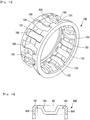
- a method of producing a holder according to the present invention can produce a holder that includes: a smaller-diameter portion; a larger-diameter portion; an inclined portion that connects the smaller-diameter portion and the larger-diameter portion; a flange portion formed in an end portion thereof; and a pocket into which a roller is inserted, the pocket being formed across the smaller-diameter portion, the larger-diameter portion, and the inclined portion.
- a thickness of a bent part of the flange portion is made larger than a plate thickness of an unbent part adjacent to the bent part. According to such a holder, because the thickness of the bent part is made larger, the strength thereof is enhanced.
- the present invention produces various effects such as an effect of producing a holder in which sagging is suppressed in a bent part to be formed into a flange portion, without using bulge forming and a split mold that restrains the inside of a working target article.
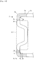
- the holder is produced by forming a flange portion in such a working target article 6 as illustrated in Fig. 7 , and a one-end diameter enlarged article 5 is made as illustrated in Fig. 1, Fig. 2, and Fig. 3 , in order to obtain the working target article 6.
- the one-end diameter enlarged article 5 is made by press-forming a circular tube 1 cut into a predetermined length.
- a circular tube member 3 is made by removing a bottom of a cup-shaped member 2 formed by drawing, and the one-end diameter enlarged article 5 is made by press-forming the circular tube member 3.
- the one-end diameter enlarged article 5 is made by removing a bottom of a one-end diameter enlarged bottomed cylindrical member 4 formed by drawing.
- Fig. 4A and Fig. 4B are explanatory views illustrating a step of making the one-end diameter enlarged article 5 from the circular tube 1 or the circular tube member 3.
- the circular tube 1 or the circular tube member 3 is set onto a lower punch 11.
- the diameter of an upper end portion 11a of the lower punch 11 is the same as the inner diameter of the circular tube 1 or the circular tube member 3.
- the diameter of a base end portion 11b of the lower punch 11 is the same as the outer diameter of the circular tube 1 or the circular tube member 3, and the circular tube 1 or the circular tube member 3 is supported by the base end portion 11b.
- a die 12 is placed on the lower punch 11.
- the inner diameter from a middle portion to a lower portion of the die 12 is the same as the outer diameter of the circular tube 1 or the circular tube member 3, and an outer peripheral surface of the circular tube 1 or the circular tube member 3 is restrained by this inner-diameter portion.
- the inner diameter of an upper portion of the die 12 is the same as the outer diameter of a larger-diameter portion of the working target article 6 illustrated in Fig. 7 .
- an upper punch 13 is provided above the lower punch 11.
- the diameter of a lower end portion 13a of the upper punch 13 is the same as the inner diameter of the circular tube 1 or the circular tube member 3, and an inner peripheral surface of the circular tube 1 or the circular tube member 3 is restrained by this inner-diameter portion.
- the diameter of a base end portion 13b of the upper punch 13 is the same as the inner diameter of the larger-diameter portion of the working target article 6.
- an inclined portion forming portion 13c corresponding to an inclined portion of the working target article 6 is formed between the lower end portion 13a and the base end portion 13b.
- a cylindrical mold member 14 that presses an upper end surface of the working target article 6 from above is provided around the upper punch 13.
- the upper punch 13 is press-fitted into the circular tube 1 or the circular tube member 3, whereby the one-end diameter enlarged article 5 is made.
- the mold member 14 presses the upper end of the one-end diameter enlarged article 5, in the state of Fig. 4B .
- the inside of a mold space formed by the inclined portion forming portion 13c is filled with the material of the one-end diameter enlarged article 5 without any gap, so that a desired inclination shape is secured.
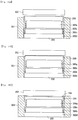
- Fig. 5A, Fig. 5B, and Fig. 5C are explanatory views illustrating a step of making the working target article 6 from the one-end diameter enlarged article 5.
- the one-end diameter enlarged article 5 is set onto a lower punch 21 with the diameter enlarged side thereof facing downward.
- the diameter of an upper end portion 21a of the lower punch 21 is the same as the inner diameter of a smaller-diameter portion of the working target article 6.
- the diameter of a base end portion 21b of the lower punch 21 is the same as the inner diameter of the larger-diameter portion of the working target article 6.
- an inclined portion 21c corresponding to the inclined portion of the working target article 6 is formed between the upper end portion 21a and the base end portion 21b.
- a split die 22 is placed around the lower punch 21.
- the split die 22 includes four split mold portions 22a in a circular pattern, and forms a circular shape corresponding to the working target article 6 in the state where the four split mold portions 22a are put together.
- a convex portion located on the central side of an inner peripheral surface of each split mold portion 22a is formed so as to coincide with the outer diameters of the smaller-diameter portion and the inclined portion of the working target article 6, and portions below and above the convex portion of each split mold portion 22a are formed so as to coincide with the outer diameter of the larger-diameter portion of the working target article 6.
- a leading end of a shaft 22b is fixed to a back surface of each split mold portion 22a.
- Each shaft 22b moves while being guided by a guide member 22c, and the split mold portions 22a are put together and separated from one another by this movement.
- a spring receiver 22e is fixed to a back end of the shaft 22b, and a spring 22d is attached between the spring receiver 22e and the guide member 22c. If a pressing force of putting the split mold portions 22a together is cancelled, the split mold portions 22a are respectively moved by extension forces of the springs 22d so as to be separated from one another.
- An upper punch 23 is placed above the lower punch 21.
- the diameter of a lower end portion 23a of the upper punch 23 is the same as the inner diameter of the smaller-diameter portion of the working target article 6.
- the diameter of a base end portion 23b of the upper punch 23 is the same as the inner diameter of the larger-diameter portion of the working target article 6.
- an inclined portion forming portion 23c corresponding to the inclined portion of the working target article 6 is formed between the lower end portion 23a and the base end portion 23b.
- a cylindrical mold member 24 that presses the upper end surface of the working target article 6 from above is provided around the upper punch 23.
- a cam member 25 that moves upward and downward in conjunction with upward and downward movement of the upper punch 23 is provided lateral to the upper punch 23.
- the cam member 25 has a tapered shape in which the cam member 25 becomes thinner toward a leading end thereof.
- the cam member 25 is fitted into a space between the split mold portions 22a and the guide members 22c, to thereby apply the pressing force of putting the split mold portions 22a together.
- the split mold portions 22a may be moved by means of a driving cylinder.
- the split mold portions 22a are guided so as to be put together, the periphery of the one-end diameter enlarged article 5 is restrained, and the upper punch 23 is press-fitted into the one-end diameter enlarged article 5, whereby the working target article 6 having both the ends at which the diameter is enlarged is made.
- the mold member 24 presses the upper end of the working target article 6.
- the inside of a mold space formed by the inclined portion forming portion 23c is filled with the material of the working target article 6 without any gap, so that a desired inclination shape is secured.
- the inclined portion forming portion 13c (23c) of the rough forming punch 13A (23A) is set to, for example, 40 to 70% of the angle ⁇ °.
- Fig. 5A, Fig. 5B, and Fig. 5C are performed as rough forming once or a plurality of times using the rough forming punch 13A (23A). Then, the press forming operation of Fig. 4A and Fig. 4B and the press forming operation of Fig. 5A, Fig. 5B, and Fig. 5C are performed as finishing forming using the upper punch 13 (23). In this way, a stress generated in the forming for diameter enlargement can be made smaller, and galling can be suppressed from occurring in the working target article 6.
- the rough forming is performed with the angle of the inclined portion forming portion 13c (23c) of the rough forming punch 13A (23A) being set to 40% or lower of the inclination angle of the inclined portion of the working target article 6, galling may occur in the working target article 6 and the mold in the subsequent finishing step. Meanwhile, if the rough forming is performed with the angle thereof being set to 70% or higher thereof, galling may occur in the working target article 6 and the mold during the rough forming. Accordingly, if the inclined portion forming portion 13c (23c) of the rough forming punch 13A (23A) is set to 40 to 70% of the angle ⁇ ° as described above, the occurrence of such galling can be suppressed.
- the working target article 6 is made by press forming in the above-mentioned example, the present invention is not limited thereto, and the working target article 6 may be made by rolling a circular tube or the like.
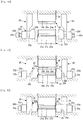
- Fig. 9A, Fig. 9B, and Fig. 9C are explanatory views illustrating a step of producing a holder 7 illustrated in Fig. 10 from the working target article 6.
- the working target article 6 is set onto a lower punch 31.
- the diameter of an upper end portion 31a of the lower punch 31 is the same as the inner diameter of a smaller-diameter portion of the holder 7.
- the diameter of a base end portion 31b of the lower punch 31 is the same as the inner diameter of a larger-diameter portion of the holder 7.
- an inclined portion 31c corresponding to an inclined portion of the holder 7 is formed between the upper end portion 31a and the base end portion 31b.
- a split die 32 is provided around the lower punch 31.
- the split die 32 includes a plurality of split mold portions 32a.
- a convex portion 32b located on the central side of an inner peripheral surface of each split mold portion 32a is formed so as to coincide with the outer diameters of the smaller-diameter portion and the inclined portion of the holder 7, and portions below and above the convex portion 32b of each split mold portion 32a are formed so as to coincide with the outer diameter of the larger-diameter portion of the holder 7.
- a driving mechanism of the split die 32 can have a configuration similar to that of the driving mechanism for the split die 22 illustrated in Fig. 5A, Fig. 5B, Fig. 5C , and Figs. 6 , but is not limited to such a configuration.
- An upper punch 33 is placed above the lower punch 31.
- the diameter of a convex portion 33a of the upper punch 33 is smaller than the inner diameter of a larger-diameter portion 7b of the holder 7 illustrated in Fig. 10 , and is the same as the diameter of a circular opening defined by an end surface 7c of a flange portion 7a of the holder 7.
- the diameter of a main body portion 33b of the upper punch 33 is equivalent to the outer diameter of the larger-diameter portion 7b of the holder 7, and a step-like receiving region is formed by a lower end surface of the main body portion 33b and a peripheral surface of the convex portion 33a.
- the upper punch 33 presses and bends one end portion of the working target article 6 inward, whereby the flange portion 7a is formed in the one end portion.
- this pressing operation when the upper punch 33 presses the end portion of the working target article 6, an inner peripheral surface of the smaller-diameter portion of the working target article 6 is received (restrained) by an outer peripheral surface of the lower punch 31 inserted into the working target article 6, and an outer peripheral surface of the smaller-diameter portion and an outer peripheral surface of the larger-diameter portion of the working target article 6 are received (restrained) by the split die 32.
- the bending operation for forming the flange portion 7a of the holder 7 illustrated in Fig. 10 can be performed. Then, in this bending operation, a peripheral surface portion of the convex portion 33a of the upper punch 33 receives the end portion of the working target article 6 and applies an outward pressure to the end portion thereof (see an arrow A in Fig. 9B ). Hence, a bent part 7d is pushed toward a larger-diameter portion restraining part of the split die 32, so that sagging is prevented from occurring in the bent part 7d.
- a thickness t a of the bent part 7d of the flange portion 7a is made larger than a plate thickness t b of an unbent part adjacent to the bent part 7d.
- the end surface 7c of the flange portion 7a is received by the peripheral surface of the convex portion 33a of the upper punch 33.
- the accuracy of an inner peripheral circular position of the flange portion 7a can be secured by the centering accuracy of the convex portion 33a of the upper punch 33.
- the end surface 7c of the flange portion 7a can be brought into pressure contact with the peripheral surface of the convex portion 33a of the upper punch 33 by the pressing operation.
- the surface roughness of the peripheral surface of the convex portion 33a of the upper punch 33 is made smaller, the surface roughness of the end surface 7c of the flange portion 7a can be made smaller.
- the lower punch 31 inserted into the working target article 6 does not need to have a splittable configuration. This is suitable for production of small holders, and facilitates application to various press forming apparatuses, particularly, a transfer press apparatus.
- the flange portion 7a is further formed on the opposite side of the working target article 6, and, for example, a mold apparatus illustrated in Fig. 11 can be used for the formation.
- This mold apparatus corresponds to an apparatus including a lower punch 34 instead of the lower punch 31 of the mold apparatus illustrated in Fig. 9A .
- the diameter of the lower punch 34 is the same as the inner diameter of the smaller-diameter portion of the holder 7, and the working target article 6 can be fitted and set to the lower punch 34 from above.
- the upper punch 33 presses and bends another end portion of the working target article 6 inward, whereby the flange portion 7a is formed also in the another end portion.
- the smaller-diameter portion of the working target article 6 is restrained from the inside and the outside by the lower punch 34 and the split mold portions 32a, and the convex portion 33a of the upper punch 33 applies an outward pressure to the end portion of the working target article 6.
- the restraint can be more reliable.
- the flange portion 7a is formed one by one on each side of the working target article 6, but the present invention is not limited thereto, and the flange portions 7a may be simultaneously formed on both the sides of the working target article 6.
- a mold apparatus illustrated in Fig. 12A and Fig. 12B can be used for the formation. This mold apparatus corresponds to an apparatus including a lower punch 35 instead of the lower punch 34 of the mold apparatus illustrated in Fig. 11 .
- the lower punch 35 includes: a first punch portion 35a for forming the flange portion 7a similarly to the upper punch 33; a second punch portion 35b for restraining the smaller-diameter portion of the working target article 6 from the inside similarly to the lower punch 34; and a shaft 35c fixed to a central portion of a lower surface of the second punch portion 35b.
- the second punch portion 35b moves together with the shaft 35c.
- the first punch portion 35a has a through-hole formed in a central portion thereof, and the shaft 35c is inserted through the through-hole. In the state where the second punch portion 35b is located at the position of the smaller-diameter portion of the working target article 6, the first punch portion 35a can press the end portion of the working target article 6 to form the flange portion 7a.
- the split mold portions 32a restrain the smaller-diameter portion and the larger-diameter portion of the working target article 6 from the outside, but the split mold portions 32a may restrain only the smaller-diameter portion from the outside, and a fixed die may be used to restrain the larger-diameter portion.
- a pocket 7f into which a needle roller 8 is inserted is formed in the holder 7.
- the pocket 7f may be formed before the formation of the flange portion 7a, and may be formed after the formation of the flange portion 7a.
Landscapes
- Engineering & Computer Science (AREA)
- General Engineering & Computer Science (AREA)
- Mechanical Engineering (AREA)
- Shaping Metal By Deep-Drawing, Or The Like (AREA)
- Forging (AREA)
- Rolling Contact Bearings (AREA)
Applications Claiming Priority (2)
| Application Number | Priority Date | Filing Date | Title |
|---|---|---|---|
| JP2012059988A JP5908762B2 (ja) | 2012-03-16 | 2012-03-16 | 保持器の製造方法及び保持器 |
| PCT/JP2013/056162 WO2013137086A1 (ja) | 2012-03-16 | 2013-03-06 | 保持器の製造方法及び保持器 |
Publications (3)
| Publication Number | Publication Date |
|---|---|
| EP2826573A1 EP2826573A1 (en) | 2015-01-21 |
| EP2826573A4 EP2826573A4 (en) | 2016-01-06 |
| EP2826573B1 true EP2826573B1 (en) | 2021-02-17 |
Family
ID=49160998
Family Applications (1)
| Application Number | Title | Priority Date | Filing Date |
|---|---|---|---|
| EP13760505.1A Active EP2826573B1 (en) | 2012-03-16 | 2013-03-06 | Method for producing a holder |
Country Status (5)
| Country | Link |
|---|---|
| US (1) | US9441672B2 (ja) |
| EP (1) | EP2826573B1 (ja) |
| JP (1) | JP5908762B2 (ja) |
| CN (1) | CN104169020B (ja) |
| WO (1) | WO2013137086A1 (ja) |
Families Citing this family (7)
| Publication number | Priority date | Publication date | Assignee | Title |
|---|---|---|---|---|
| CN103658446B (zh) * | 2013-11-18 | 2015-09-30 | 大连鑫雨轴承有限公司 | 冲压内k形carb轴承保持架的制作方法 |
| DE102014223824A1 (de) * | 2014-11-21 | 2016-05-25 | Aktiebolaget Skf | Drückwalzen von Lagerringen |
| US9866337B2 (en) * | 2015-03-31 | 2018-01-09 | The Regents Of The University Of California | System and method of occupancy estimation utilizing transmitted signals |
| CN106583587A (zh) * | 2016-12-13 | 2017-04-26 | 苏州和林微纳科技有限公司 | 超高端面要求旋切冲孔产品预制件 |
| US10499186B2 (en) * | 2017-06-02 | 2019-12-03 | Apple Inc. | User interface for providing offline access to maps |
| DE102019204010A1 (de) * | 2019-03-25 | 2020-10-01 | Aktiebolaget Skf | Lagerkäfig |
| USD964147S1 (en) * | 2020-09-08 | 2022-09-20 | Rockit Global Limited | Conveyor line holder for supporting an item of produce |
Family Cites Families (17)
| Publication number | Priority date | Publication date | Assignee | Title |
|---|---|---|---|---|
| JPS54110962A (en) * | 1978-02-20 | 1979-08-30 | Sanyo Electric Co Ltd | Shaping of pipe ends |
| JPH03169442A (ja) | 1989-11-29 | 1991-07-23 | Ntn Corp | M形保持器の製造方法 |
| JP4246310B2 (ja) | 1999-01-12 | 2009-04-02 | Ntn株式会社 | ころ軸受用保持器の製造方法 |
| JP2000257638A (ja) | 1999-03-04 | 2000-09-19 | Nippon Thompson Co Ltd | ころ軸受用保持器及びその製造方法 |
| JP4320599B2 (ja) * | 2004-02-20 | 2009-08-26 | 日本精工株式会社 | ラジアルニードル軸受用保持器の製造方法 |
| JP2006007246A (ja) * | 2004-06-23 | 2006-01-12 | Nsk Ltd | ラジアルニードル軸受用保持器の製造方法及び製造装置 |
| US20080219611A1 (en) | 2005-04-25 | 2008-09-11 | Nsk Ltd. | Cage for Radial Needle Bearing, Method for Manufacturing the Same and Radial Needle Bearing |
| CN101166916A (zh) * | 2005-04-25 | 2008-04-23 | 日本精工株式会社 | 用于径向滚针轴承的保持架、制造保持架的方法以及径向滚针轴承 |
| JP4442547B2 (ja) * | 2005-11-09 | 2010-03-31 | 日本精工株式会社 | ラジアルニードル軸受用保持器の製造方法及び製造装置 |
| JP2008007246A (ja) * | 2006-06-28 | 2008-01-17 | Shinko Electric Ind Co Ltd | ベルト調整装置、ベルト調整方法および搬送装置 |
| JP4703521B2 (ja) * | 2006-09-08 | 2011-06-15 | Ntn株式会社 | 保持器付きころ |
| DE102007024357B3 (de) * | 2007-05-24 | 2008-10-09 | Witzig & Frank Gmbh | Verfahren und Vorrichtung zur Herstellung von Rohranschlüssen |
| DE102007030217A1 (de) * | 2007-06-29 | 2009-01-08 | Schaeffler Kg | Käfig |
| JP2009156392A (ja) * | 2007-12-27 | 2009-07-16 | Ntn Corp | ころ軸受用保持器、針状ころ軸受、およびころ軸受用保持器の製造方法 |
| WO2009084478A1 (ja) * | 2007-12-27 | 2009-07-09 | Ntn Corporation | ころ軸受用保持器および針状ころ軸受 |
| JP2009264400A (ja) * | 2008-04-22 | 2009-11-12 | Ntn Corp | 保持器の製造方法およびその保持器 |
| JP5534804B2 (ja) * | 2009-12-25 | 2014-07-02 | Ntn株式会社 | 保持器の製造方法、保持器、および針状ころ軸受 |
-
2012
- 2012-03-16 JP JP2012059988A patent/JP5908762B2/ja active Active
-
2013
- 2013-03-06 WO PCT/JP2013/056162 patent/WO2013137086A1/ja active Application Filing
- 2013-03-06 CN CN201380014299.XA patent/CN104169020B/zh active Active
- 2013-03-06 US US14/384,918 patent/US9441672B2/en active Active
- 2013-03-06 EP EP13760505.1A patent/EP2826573B1/en active Active
Non-Patent Citations (1)
| Title |
|---|
| None * |
Also Published As
| Publication number | Publication date |
|---|---|
| EP2826573A1 (en) | 2015-01-21 |
| CN104169020B (zh) | 2017-06-30 |
| JP5908762B2 (ja) | 2016-04-26 |
| EP2826573A4 (en) | 2016-01-06 |
| CN104169020A (zh) | 2014-11-26 |
| US9441672B2 (en) | 2016-09-13 |
| US20150036961A1 (en) | 2015-02-05 |
| WO2013137086A1 (ja) | 2013-09-19 |
| JP2013193088A (ja) | 2013-09-30 |
Similar Documents
| Publication | Publication Date | Title |
|---|---|---|
| EP2826573B1 (en) | Method for producing a holder | |
| US20150352622A1 (en) | Method for forming a pressed component, method for manufacturing a pressed component, and die apparatus for forming a pressed component | |
| US8875555B2 (en) | Bossed disc-like member manufacturing method and bossed disc-like member manufacturing apparatus | |
| US10029296B2 (en) | Forming die, and undercut forming method | |
| JP6414957B2 (ja) | 缶の製造方法、ボトムリフォーム機構及びこれに用いるトップ支持部材 | |
| RU2634830C2 (ru) | Устройство, установка и способ формования листовой металлической заготовки, и полученная таким образом деталь | |
| EP3248704B1 (en) | Flanging method | |
| CN104736269A (zh) | 冲压加工方法及带底容器 | |
| CN105592946B (zh) | 截面形状在长度方向上变化的型钢的制造方法和辊轧成形装置 | |
| CN105682823B (zh) | 带底圆筒容器的成形方法 | |
| CN104741433A (zh) | 冲裁模具装置和层叠铁芯的制造方法 | |
| CN105710215A (zh) | 一种用于笔记本电子器件固定板的冲孔折弯模具 | |
| US20070125147A1 (en) | Method of forming a part | |
| US20130333435A1 (en) | Draw Die Set with Rolling Elements on Punch and Draw Die Cavity | |
| JP2005273755A (ja) | スラスト円筒ころ軸受用保持器とその製造方法 | |
| EP3308873B1 (en) | Method of manufacturing a washer | |
| JP4607690B2 (ja) | 絞り/しごき成形装置および成形方法 | |
| CN102758848B (zh) | 滚动轴承以及用于制造滚动轴承的方法和设备 | |
| JP6787013B2 (ja) | 成形材製造方法 | |
| US20230249239A1 (en) | Workpiece production apparatus | |
| JP2011240394A (ja) | 有底筒状部材の製造方法 | |
| WO2023189155A1 (ja) | 角型缶製造方法および角型缶製造装置 | |
| JP5924005B2 (ja) | ハブユニットの製造方法 | |
| JP2010094720A (ja) | 逐次成形装置およびその方法 | |
| JP2008256004A (ja) | シェル外輪の製造方法およびシェル型針状ころ軸受 |
Legal Events
| Date | Code | Title | Description |
|---|---|---|---|
| PUAI | Public reference made under article 153(3) epc to a published international application that has entered the european phase |
Free format text: ORIGINAL CODE: 0009012 |
|
| 17P | Request for examination filed |
Effective date: 20141013 |
|
| AK | Designated contracting states |
Kind code of ref document: A1 Designated state(s): AL AT BE BG CH CY CZ DE DK EE ES FI FR GB GR HR HU IE IS IT LI LT LU LV MC MK MT NL NO PL PT RO RS SE SI SK SM TR |
|
| AX | Request for extension of the european patent |
Extension state: BA ME |
|
| DAX | Request for extension of the european patent (deleted) | ||
| RA4 | Supplementary search report drawn up and despatched (corrected) |
Effective date: 20151208 |
|
| RIC1 | Information provided on ipc code assigned before grant |
Ipc: F16C 33/54 20060101ALI20151202BHEP Ipc: B21D 53/12 20060101ALI20151202BHEP Ipc: B21K 1/05 20060101AFI20151202BHEP Ipc: B21J 5/08 20060101ALI20151202BHEP Ipc: B21D 41/02 20060101ALI20151202BHEP Ipc: F16C 33/46 20060101ALI20151202BHEP |
|
| STAA | Information on the status of an ep patent application or granted ep patent |
Free format text: STATUS: EXAMINATION IS IN PROGRESS |
|
| 17Q | First examination report despatched |
Effective date: 20190121 |
|
| GRAP | Despatch of communication of intention to grant a patent |
Free format text: ORIGINAL CODE: EPIDOSNIGR1 |
|
| STAA | Information on the status of an ep patent application or granted ep patent |
Free format text: STATUS: GRANT OF PATENT IS INTENDED |
|
| INTG | Intention to grant announced |
Effective date: 20201002 |
|
| GRAS | Grant fee paid |
Free format text: ORIGINAL CODE: EPIDOSNIGR3 |
|
| GRAA | (expected) grant |
Free format text: ORIGINAL CODE: 0009210 |
|
| STAA | Information on the status of an ep patent application or granted ep patent |
Free format text: STATUS: THE PATENT HAS BEEN GRANTED |
|
| AK | Designated contracting states |
Kind code of ref document: B1 Designated state(s): AL AT BE BG CH CY CZ DE DK EE ES FI FR GB GR HR HU IE IS IT LI LT LU LV MC MK MT NL NO PL PT RO RS SE SI SK SM TR |
|
| REG | Reference to a national code |
Ref country code: GB Ref legal event code: FG4D |
|
| REG | Reference to a national code |
Ref country code: CH Ref legal event code: EP |
|
| REG | Reference to a national code |
Ref country code: DE Ref legal event code: R096 Ref document number: 602013075677 Country of ref document: DE |
|
| REG | Reference to a national code |
Ref country code: AT Ref legal event code: REF Ref document number: 1360813 Country of ref document: AT Kind code of ref document: T Effective date: 20210315 |
|
| REG | Reference to a national code |
Ref country code: IE Ref legal event code: FG4D |
|
| REG | Reference to a national code |
Ref country code: LT Ref legal event code: MG9D |
|
| REG | Reference to a national code |
Ref country code: NL Ref legal event code: MP Effective date: 20210217 |
|
| PG25 | Lapsed in a contracting state [announced via postgrant information from national office to epo] |
Ref country code: HR Free format text: LAPSE BECAUSE OF FAILURE TO SUBMIT A TRANSLATION OF THE DESCRIPTION OR TO PAY THE FEE WITHIN THE PRESCRIBED TIME-LIMIT Effective date: 20210217 Ref country code: GR Free format text: LAPSE BECAUSE OF FAILURE TO SUBMIT A TRANSLATION OF THE DESCRIPTION OR TO PAY THE FEE WITHIN THE PRESCRIBED TIME-LIMIT Effective date: 20210518 Ref country code: FI Free format text: LAPSE BECAUSE OF FAILURE TO SUBMIT A TRANSLATION OF THE DESCRIPTION OR TO PAY THE FEE WITHIN THE PRESCRIBED TIME-LIMIT Effective date: 20210217 Ref country code: LT Free format text: LAPSE BECAUSE OF FAILURE TO SUBMIT A TRANSLATION OF THE DESCRIPTION OR TO PAY THE FEE WITHIN THE PRESCRIBED TIME-LIMIT Effective date: 20210217 Ref country code: PT Free format text: LAPSE BECAUSE OF FAILURE TO SUBMIT A TRANSLATION OF THE DESCRIPTION OR TO PAY THE FEE WITHIN THE PRESCRIBED TIME-LIMIT Effective date: 20210617 Ref country code: BG Free format text: LAPSE BECAUSE OF FAILURE TO SUBMIT A TRANSLATION OF THE DESCRIPTION OR TO PAY THE FEE WITHIN THE PRESCRIBED TIME-LIMIT Effective date: 20210517 Ref country code: NO Free format text: LAPSE BECAUSE OF FAILURE TO SUBMIT A TRANSLATION OF THE DESCRIPTION OR TO PAY THE FEE WITHIN THE PRESCRIBED TIME-LIMIT Effective date: 20210517 |
|
| REG | Reference to a national code |
Ref country code: AT Ref legal event code: MK05 Ref document number: 1360813 Country of ref document: AT Kind code of ref document: T Effective date: 20210217 |
|
| PG25 | Lapsed in a contracting state [announced via postgrant information from national office to epo] |
Ref country code: RS Free format text: LAPSE BECAUSE OF FAILURE TO SUBMIT A TRANSLATION OF THE DESCRIPTION OR TO PAY THE FEE WITHIN THE PRESCRIBED TIME-LIMIT Effective date: 20210217 Ref country code: PL Free format text: LAPSE BECAUSE OF FAILURE TO SUBMIT A TRANSLATION OF THE DESCRIPTION OR TO PAY THE FEE WITHIN THE PRESCRIBED TIME-LIMIT Effective date: 20210217 Ref country code: NL Free format text: LAPSE BECAUSE OF FAILURE TO SUBMIT A TRANSLATION OF THE DESCRIPTION OR TO PAY THE FEE WITHIN THE PRESCRIBED TIME-LIMIT Effective date: 20210217 Ref country code: LV Free format text: LAPSE BECAUSE OF FAILURE TO SUBMIT A TRANSLATION OF THE DESCRIPTION OR TO PAY THE FEE WITHIN THE PRESCRIBED TIME-LIMIT Effective date: 20210217 Ref country code: SE Free format text: LAPSE BECAUSE OF FAILURE TO SUBMIT A TRANSLATION OF THE DESCRIPTION OR TO PAY THE FEE WITHIN THE PRESCRIBED TIME-LIMIT Effective date: 20210217 |
|
| PG25 | Lapsed in a contracting state [announced via postgrant information from national office to epo] |
Ref country code: IS Free format text: LAPSE BECAUSE OF FAILURE TO SUBMIT A TRANSLATION OF THE DESCRIPTION OR TO PAY THE FEE WITHIN THE PRESCRIBED TIME-LIMIT Effective date: 20210617 |
|
| PG25 | Lapsed in a contracting state [announced via postgrant information from national office to epo] |
Ref country code: SM Free format text: LAPSE BECAUSE OF FAILURE TO SUBMIT A TRANSLATION OF THE DESCRIPTION OR TO PAY THE FEE WITHIN THE PRESCRIBED TIME-LIMIT Effective date: 20210217 Ref country code: AT Free format text: LAPSE BECAUSE OF FAILURE TO SUBMIT A TRANSLATION OF THE DESCRIPTION OR TO PAY THE FEE WITHIN THE PRESCRIBED TIME-LIMIT Effective date: 20210217 Ref country code: CZ Free format text: LAPSE BECAUSE OF FAILURE TO SUBMIT A TRANSLATION OF THE DESCRIPTION OR TO PAY THE FEE WITHIN THE PRESCRIBED TIME-LIMIT Effective date: 20210217 Ref country code: EE Free format text: LAPSE BECAUSE OF FAILURE TO SUBMIT A TRANSLATION OF THE DESCRIPTION OR TO PAY THE FEE WITHIN THE PRESCRIBED TIME-LIMIT Effective date: 20210217 |
|
| REG | Reference to a national code |
Ref country code: CH Ref legal event code: PL |
|
| REG | Reference to a national code |
Ref country code: DE Ref legal event code: R097 Ref document number: 602013075677 Country of ref document: DE |
|
| PG25 | Lapsed in a contracting state [announced via postgrant information from national office to epo] |
Ref country code: DK Free format text: LAPSE BECAUSE OF FAILURE TO SUBMIT A TRANSLATION OF THE DESCRIPTION OR TO PAY THE FEE WITHIN THE PRESCRIBED TIME-LIMIT Effective date: 20210217 Ref country code: ES Free format text: LAPSE BECAUSE OF FAILURE TO SUBMIT A TRANSLATION OF THE DESCRIPTION OR TO PAY THE FEE WITHIN THE PRESCRIBED TIME-LIMIT Effective date: 20210217 Ref country code: MC Free format text: LAPSE BECAUSE OF FAILURE TO SUBMIT A TRANSLATION OF THE DESCRIPTION OR TO PAY THE FEE WITHIN THE PRESCRIBED TIME-LIMIT Effective date: 20210217 Ref country code: SK Free format text: LAPSE BECAUSE OF FAILURE TO SUBMIT A TRANSLATION OF THE DESCRIPTION OR TO PAY THE FEE WITHIN THE PRESCRIBED TIME-LIMIT Effective date: 20210217 Ref country code: RO Free format text: LAPSE BECAUSE OF FAILURE TO SUBMIT A TRANSLATION OF THE DESCRIPTION OR TO PAY THE FEE WITHIN THE PRESCRIBED TIME-LIMIT Effective date: 20210217 |
|
| REG | Reference to a national code |
Ref country code: BE Ref legal event code: MM Effective date: 20210331 |
|
| PLBE | No opposition filed within time limit |
Free format text: ORIGINAL CODE: 0009261 |
|
| STAA | Information on the status of an ep patent application or granted ep patent |
Free format text: STATUS: NO OPPOSITION FILED WITHIN TIME LIMIT |
|
| 26N | No opposition filed |
Effective date: 20211118 |
|
| GBPC | Gb: european patent ceased through non-payment of renewal fee |
Effective date: 20210517 |
|
| PG25 | Lapsed in a contracting state [announced via postgrant information from national office to epo] |
Ref country code: AL Free format text: LAPSE BECAUSE OF FAILURE TO SUBMIT A TRANSLATION OF THE DESCRIPTION OR TO PAY THE FEE WITHIN THE PRESCRIBED TIME-LIMIT Effective date: 20210217 Ref country code: CH Free format text: LAPSE BECAUSE OF NON-PAYMENT OF DUE FEES Effective date: 20210331 Ref country code: LI Free format text: LAPSE BECAUSE OF NON-PAYMENT OF DUE FEES Effective date: 20210331 Ref country code: LU Free format text: LAPSE BECAUSE OF NON-PAYMENT OF DUE FEES Effective date: 20210306 Ref country code: IE Free format text: LAPSE BECAUSE OF NON-PAYMENT OF DUE FEES Effective date: 20210306 |
|
| PG25 | Lapsed in a contracting state [announced via postgrant information from national office to epo] |
Ref country code: SI Free format text: LAPSE BECAUSE OF FAILURE TO SUBMIT A TRANSLATION OF THE DESCRIPTION OR TO PAY THE FEE WITHIN THE PRESCRIBED TIME-LIMIT Effective date: 20210217 |
|
| PG25 | Lapsed in a contracting state [announced via postgrant information from national office to epo] |
Ref country code: IT Free format text: LAPSE BECAUSE OF FAILURE TO SUBMIT A TRANSLATION OF THE DESCRIPTION OR TO PAY THE FEE WITHIN THE PRESCRIBED TIME-LIMIT Effective date: 20210217 Ref country code: GB Free format text: LAPSE BECAUSE OF NON-PAYMENT OF DUE FEES Effective date: 20210517 |
|
| PG25 | Lapsed in a contracting state [announced via postgrant information from national office to epo] |
Ref country code: IS Free format text: LAPSE BECAUSE OF FAILURE TO SUBMIT A TRANSLATION OF THE DESCRIPTION OR TO PAY THE FEE WITHIN THE PRESCRIBED TIME-LIMIT Effective date: 20210617 |
|
| PG25 | Lapsed in a contracting state [announced via postgrant information from national office to epo] |
Ref country code: BE Free format text: LAPSE BECAUSE OF NON-PAYMENT OF DUE FEES Effective date: 20210331 |
|
| PGFP | Annual fee paid to national office [announced via postgrant information from national office to epo] |
Ref country code: FR Payment date: 20230221 Year of fee payment: 11 |
|
| PG25 | Lapsed in a contracting state [announced via postgrant information from national office to epo] |
Ref country code: HU Free format text: LAPSE BECAUSE OF FAILURE TO SUBMIT A TRANSLATION OF THE DESCRIPTION OR TO PAY THE FEE WITHIN THE PRESCRIBED TIME-LIMIT; INVALID AB INITIO Effective date: 20130306 |
|
| PGFP | Annual fee paid to national office [announced via postgrant information from national office to epo] |
Ref country code: DE Payment date: 20230214 Year of fee payment: 11 |
|
| PG25 | Lapsed in a contracting state [announced via postgrant information from national office to epo] |
Ref country code: CY Free format text: LAPSE BECAUSE OF FAILURE TO SUBMIT A TRANSLATION OF THE DESCRIPTION OR TO PAY THE FEE WITHIN THE PRESCRIBED TIME-LIMIT Effective date: 20210217 |
|
| PG25 | Lapsed in a contracting state [announced via postgrant information from national office to epo] |
Ref country code: MK Free format text: LAPSE BECAUSE OF FAILURE TO SUBMIT A TRANSLATION OF THE DESCRIPTION OR TO PAY THE FEE WITHIN THE PRESCRIBED TIME-LIMIT Effective date: 20210217 |
|
| PGFP | Annual fee paid to national office [announced via postgrant information from national office to epo] |
Ref country code: DE Payment date: 20240130 Year of fee payment: 12 |