EP2825968B1 - Modulares serversystem, i/o-modul und switching-verfahren - Google Patents
Modulares serversystem, i/o-modul und switching-verfahren Download PDFInfo
- Publication number
- EP2825968B1 EP2825968B1 EP13704380.8A EP13704380A EP2825968B1 EP 2825968 B1 EP2825968 B1 EP 2825968B1 EP 13704380 A EP13704380 A EP 13704380A EP 2825968 B1 EP2825968 B1 EP 2825968B1
- Authority
- EP
- European Patent Office
- Prior art keywords
- server
- group
- components
- groups
- module
- Prior art date
- Legal status (The legal status is an assumption and is not a legal conclusion. Google has not performed a legal analysis and makes no representation as to the accuracy of the status listed.)
- Not-in-force
Links
Images



Classifications
-
- G—PHYSICS
- G06—COMPUTING OR CALCULATING; COUNTING
- G06F—ELECTRIC DIGITAL DATA PROCESSING
- G06F13/00—Interconnection of, or transfer of information or other signals between, memories, input/output devices or central processing units
- G06F13/38—Information transfer, e.g. on bus
- G06F13/40—Bus structure
- G06F13/4004—Coupling between buses
- G06F13/4022—Coupling between buses using switching circuits, e.g. switching matrix, connection or expansion network
-
- H—ELECTRICITY
- H04—ELECTRIC COMMUNICATION TECHNIQUE
- H04L—TRANSMISSION OF DIGITAL INFORMATION, e.g. TELEGRAPHIC COMMUNICATION
- H04L67/00—Network arrangements or protocols for supporting network services or applications
- H04L67/14—Session management
- H04L67/141—Setup of application sessions
Definitions
- the present invention relates to a modular server system comprising a plurality of server modules and a plurality of I / O components.
- the invention further relates to an I / O module and a switching method for such a modular server system.
- Modular server systems are known in the art.
- blade server systems in which a plurality of blade server modules, which each have at least one processor and associated main memory, access a shared infrastructure, in particular power supplies, network switches and / or mass storage components.
- the necessary connections between the blade server modules and the shared I / O components are usually made via a so-called midplane, a passive, shared circuit board of the blade server system.
- server modules in the form of rack servers are known, which are inserted into a common rack housing and access via cable connections to common network switches.
- server modules are to be connected to a plurality of I / O components, there are different possibilities for their data-related coupling.
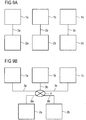
- the Figure 9A shows a first way to connect a plurality of I / O components to a plurality of server modules.
- each server module 1a to 1c exactly one I / O component 2a to 2c assigned directly.
- the assignment between the server modules 1a to 1c and the corresponding I / O components 2a to 2c takes place via electrical connections 3a to 3c of a server system.
- intervening connections 3a to 3c may be made relatively simple. In particular, these may be printed conductors on a backplane or other passive electrical connections.
- the in the Figure 9A The architecture shown has the disadvantage that in the event of failure of any I / O component 2 a to 2 c or connection 3 a to 3 c, the associated server module 1 a to 1 c can no longer execute tasks assigned to it and is thus no longer available. Furthermore, the in the Figure 9A This architecture is relatively inefficient because I / O components 2a to 2c, such as network cards, must be provided separately for each server module 1a to 1c, even though each of the server modules 1a to 1c requires only a small bandwidth shared by a single network card could be provided for all server modules 1a to 1c.
- FIG. 9B shows one opposite the Figure 9A more flexible architecture.
- three server modules 1a to 1c share two I / O components 2a and 2b.
- the connections between the server modules 1a to 1c and the I / O components 2a and 2b are made via a switch element 4.
- the switch element 4 selectively connects first connections 3a to 3c between the server modules 1a to 1c and the switch element 4 to second connections 8a and 8b between the switch element 4 and the I / O components 2a and 2b, respectively.
- an optional connection between any server module 1a to 1c and any I / O component 2a or 2b can be made.
- the described architecture has the advantage that I / O components 2a and 2b can be used jointly by the server modules 1a to 1c, which increases both the utilization of the individual I / O components 2a and 2b and their availability. For example, a single network card may be shared by all three server modules 1a to 1c. If the I / O components 2a and 2b are comparable components, for example two type-identical network cards, even if one of the two I / O components 2a or 2b fails, all server modules 1a to 1c can still successfully establish network connections.
- connection fabric A disadvantage of in the FIG. 9B
- the architecture shown is that the connection between the server modules 1a to 1c on the one hand and the I / O components 2a and 2b on the other hand, also referred to as so-called connection fabric, is relatively complicated.
- an active component namely the switch element 4, which increases both the manufacturing costs and the complexity of the server system is required for establishing the connections 3.
- a single switch element 4 for making all connections
- the problem of a so-called "single point of failure" results, in the event of failure of which all server modules 1a to 1c fail.
- such a switch element 4 could be arranged only in a central component of the modular server system, such as a backplane or midplane, which would significantly increase their cost.
- FIG. 9B Another major problem of the architecture according to FIG. 9B is the fact that, especially when using multi-core compounds 3a to 3e and 8a and 8b, as they are used especially in particularly powerful bus systems such as the so-called PCI Express standard, the number of lines to be interconnected very strongly with the number of used server modules and I / O components is increasing. From the in the FIG. 9B In the case of a server system with m server modules and n I / O components, the illustrated 3 ⁇ 2 switch element 4 is a very complex mxn switch element in the production. As the number of switch connections to server modules 1 and I / O components 2 increases, implementation of the switch element 3 becomes increasingly difficult.
- the object of the present invention is to describe an alternative architecture for modular server systems and methods for their operation.
- the solutions described are intended particularly suitable for high performance cluster applications and / or high availability systems.
- modular server architectures which allow coupling of a plurality of server modules to a plurality of I / O components.
- a modular server system which comprises a plurality of server groups, wherein each server group is set up to accommodate a plurality of server modules.
- the server system further includes a plurality of I / O groups, each I / O group configured to receive a plurality of I / O components and having a switch arrangement with at least one switch element.
- each of the plurality of I / O groups is assigned to exactly one of the plurality of server groups.
- the switch arrangement of each I / O group is directly coupled to each of the plurality of I / O components of the I / O group and to each of the plurality of server modules of the server group associated with the I / O group.
- the switch arrangement of each I / O group is data-coupled with at least one other switch arrangement of another I / O group.
- a modular, distributed switch architecture can be implemented for a modular server system.
- I / O components of an I / O group are connected via a switch arrangement with at least one switch element of the I / O group in a relatively short path with associated server modules of an associated server group so that a relatively small number of server modules can access a relatively small number of high bandwidth, low latency I / O components.
- Other connections, ie to I / O components of I / O groups that are assigned to a different server group, are made via further connections between switch arrangements or the switch elements contained therein.
- a modular server system which comprises a plurality of server groups, wherein each server group is set up to accommodate a plurality of server modules and has a switch arrangement with at least one switch element.
- the server system further includes a plurality of I / O groups, each I / O group configured to receive a plurality of I / O components.
- each of the plurality of server groups is assigned to exactly one of the plurality of I / O groups.
- the switch arrangement of each server group is directly coupled to each of the plurality of server modules of the server group and to each of the plurality of I / O modules of the I / O group associated with the server group.
- the switch arrangement of each server group is data-coupled with at least one other switch arrangement of another server group.
- the modular server system according to the alternative embodiment has substantially the same properties as that of the first embodiment, wherein the logical association between server groups on the one hand and I / O groups on the other hand is reversed.
- connection fabric An advantage of these distributed switch architectures is that the number of wires, and thus the cost of the so-called connection fabric, does not increase exponentially with the system size but only with the size of the server groups and / or I / O groups used. In this way, the complexity and cost of the modular server system can be reduced while ensuring a high level of performance, availability, and redundancy.
- the connections between the individual components are produced via a common printed circuit board, in particular a backplane or a midplane of the modular server system.
- a common printed circuit board in particular a backplane or a midplane of the modular server system.
- passive components in particular electrical connections in the form of printed conductors for data-technical coupling of the individual components are applied to the common printed circuit board.
- the server system described is particularly suitable for data-linkage of point-to-point connections with a plurality of data lines, such as connections according to the PCI Express standard.
- the I / O components are preferably components which can be shared by a plurality of server modules, for example network components having a plurality of virtual and / or physical functional units or mass storage components such as so-called solid state disks (SSD) and host bus adapters (HBA ).
- SSD solid state disks
- HBA host bus adapters
- an I / O module for use in a modular server system.
- the I / O module comprises at least one module circuit board, at least one first connection for a first I / O component arranged on the module circuit board, at least one second connection for a second I / O component arranged on the module circuit board and at least one on the module circuit board arranged connectors for data communication coupling of the I / O module with a common circuit board of the modular server system.
- On the module board is at least one switch element for selectively establishing connections between a predetermined group of server modules of the modular server system associated with the I / O module and the first and / or second I / O component and for manufacturing Connections between the predetermined group of server modules of the modular server system and a similar I / O module arranged.
- Such an I / O module with one or more integrated switch elements allows the construction of modular server systems with a common, preferably passive printed circuit board.
- connections are made between the first and the second I / O component and a server group assigned to the I / O module directly via an integrated switch element.
- indirect connections to other I / O modules can be made via a switch element of the I / O module and a switch element of a similar, adjacent I / O module.
- a switching method for a modular server system wherein first data connections between a first component of a first type of a first group of like ones Components, in particular between a server module of a plurality of server modules of a first server group, with a second component of a second type of a second group of similar components, in particular an I / O component of a plurality of I / O components of a first I / O group , are produced directly via a first switch element of the second group.
- second data connections between the first component of the first group and a third component of the second type in particular an I / O component of a plurality of I / O components of a second I / O group, are indirectly transmitted via the first switch.
- Element of the second group and a second switch element of the third group made.
- Such a distributed and optionally cascadable switching method allows the needs-based and simple connection of a plurality of server modules with a plurality of I / O components.
- FIG. 1 shows a modular server system 5 according to a first embodiment.
- the modular server system 5 comprises eight server modules 1a to 1h in two server groups 6a and 6b.
- Each of the server groups 6a and 6b includes four server modules 1a to 1d and 1e to 1h, respectively.
- Each server module 1 comprises at least one processor and typically memory for executing one or more programs running on the server system 5.
- the modular server system 5 further comprises eight I / O components 2a to 2h, which are also arranged in two I / O groups 7a and 7b.
- each I / O group 7a and 7b includes an associated switch element 4a and 4b, respectively.
- the I / O components 2 are, for example, network cards, mass storage devices or other extensions that the server modules 1 can access when executing programs.
- the exemplary embodiment described is, in particular, I / O components for connection to one or more server modules 1 via a PCI Express bus.
- the I / O components preferably support a so-called "PCI-Express device sharing", ie their simultaneous use by a plurality of root devices, in particular server modules 1.
- the switch elements 4a and 4b are switch elements for connecting a plurality of PCI Express data lines, also known as PCI-Express lanes.
- Each of the server modules 1a to 1d of the first server group 6a is directly connected to the switch element 4a of the first I / O group 7a via its own first connection 3a to 3d.
- each I / O component 2a to 2d of the first I / O group 7a is connected directly to the first switch element 4a via its own second connection 8a to 8d.
- the server modules 1e to 1h and the I / O components 2e to 2h are connected to the second switch element 4b of the second I / O group 7b via first connections 3e to 3h and second connections 8e to 8h, respectively.
- the first switch element 4a is connected via a third connection 9 to the second switch element 4b.
- all connections 3, 8 and 9 correspond to the PCI Express X16 standard, ie each have 16 differential data lines for the parallel transmission and reception of data.
- the links 3a to 3h, 8a to 8h and 9 and the switch elements 4a and 4b establish a connection fabric 10 of the modular server system 5 that allows selective connection of each server module 1 to each of the I / O components 2.
- the full bandwidth of a PCI Express X16 connection is available for each individual switched connection within a server group 6 and an associated I / O group 7.
- the Indian FIG. 1 The architecture is based on the knowledge that access frequencies, durations and intensities between server modules 1 on the one hand and I / O components 2 on the other hand are distributed unequally.
- the system is configured to access local I / O components 2, such as mass storage components with local working data for one CPU of a server module 1, relatively frequently, while others I / O components 2 is accessed only relatively infrequently.
- the system is configured to access the primary I / O components 2 of a server module 1 relatively frequently, while only in the event of a failure of a primary I / O component 2 to a redundantly held secondary I / O component 2 accesses.
- the architecture has according to FIG. 1 the advantage that with a corresponding distribution of the I / O components 2 and server modules 1, the server modules 1a to 1d of the first server group 6a with high bandwidth and low latency via a dedicated data connection to all components 2a to 2d of the first I / O group 7a can access.
- access to other I / O components 2e to 2h of the second server group 7b remains possible via the connection 9 in the exceptional case, without the need for further dedicated connections between the server modules 1a to 1d of the first server group 6a and the second switch element 4b would.
- such data connections are made over a single or few shared third links 9, for example, in time division multiplex.
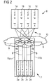
- FIG. 2 shows a part of a modular server system 5, which is particularly suitable for implementing high-availability systems.
- Four identical server modules 1a to 1d of a single server group 6 access four shared I / O components 2a to 2d.
- these are divided into two subgroups 11a and 11b.
- the secondary I / O components are the same 2c and 2d of the second subgroup 11b functionally represent the primary I / O components 2a and 2b of the first subgroup 11a.
- subgroups 11a and 11b form an I / O group 7 associated with server group 6.
- each of the server modules 1a to 1d is connected via two separate first connections 3 to a first switch element 4a of the first subgroup 11a and a second switch element 4b of the second subgroup 11b, respectively.
- the two switch elements 4a and 4b together form a switch arrangement of the I / O group 7.
- the first switch element 4a and the second switch element 4b are each a single one second connection 8 connected directly to the I / O components 2a and 2b or 2c and 2d.
- third links 9 it is not necessary on the in the FIG. 2 only indicated third links 9 to access adjacent I / O groups 7.
- the first switch element 4a or the first I / O component 2a fails, the first server module 1a can continue a program executed by it using the second switch element 4b and the similar I / O component 2c. Only when at least two of the mutually redundant components of the I / O group 7 fail, access via the third connections 9 to components of adjacent I / O groups 7 is required, as described below with reference to FIGS FIG. 3 is described.
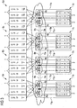
- FIG. 3 shows the connection of a plurality of groups 7 and subgroups 11 according to FIG FIG. 2 in a modular server system 5.
- FIG. 3 illustrated embodiment access a total of 16 server modules 1, which are divided into four equal server groups 6a to 6d of four server modules 1, to a total of 16 I / O components, which also in four I / O groups 7a to 7d, each with four I / O components 2 are structured.
- each of the I / O groups 7a to 7d is subdivided into a first subgroup 11a and a second subgroup 11b, as described above with respect to FIG FIG. 2 is described.
- connection 9a and 9b are provided between two adjacent I / O groups 7.
- the connections 9a and 9b may be provided, for example, via a shared circuit board such as the backplane of the modular server system 5.
- the switch element 4a of the first subgroup 11a of each I / O group 7 is coupled to the one or more neighbor links 9a and the switch element 4b of the second subgroup 11b of each I / O group 7 is coupled to the neighbor link (s) 9b coupled.
- the result is a fully redundant modular server system 5 that offers a particularly high degree of availability, performance and flexibility.
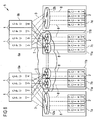
- FIG. 4A shows another possible connection scheme for two switch elements 4a and 4b of a redundant I / O group 7 with two subgroups 11a and 11b.
- the first connections 3 between the switch elements 4a or 4b and one of a total of four server modules 1a to 1d of a server group 6 are in each case PCI Express X8 connections with respectively eight differential line pairs for transmission and reception.
- the second connections 8a to 8d between the switch elements 4a and 4b and four I / O components 2a to 2d are embodied in the exemplary embodiment as PCI Express X16 connections with 16 differential pairs of lines for transmission and reception.
- each switch element 4a and 4b is provided with two third connections 9a and 9b in the form of PCI Express X8 links each having eight differential pairs of lines for transmission and reception.
- PCI Express switch modules with 81 freely configurable PCI-Express lanes are suitable.
- the connections for the connections 3 and 8 are each configured as end points, while the connections for the connections 9 are configured as routing connections.
- the remaining 81. Connection is used in an embodiment for control purposes and is coupled, for example, with other switch elements, a system management block or other control component of the server system.
- a particularly powerful I / O component 2a such as a mass storage system used simultaneously by two server modules 1a and 1b, may connect to the server module 1a and 1b via a second connection 8a at a higher connection speed than the first two connections 3 Switch element 4a are connected.
- the advantage here is that the second connections with a high number of interconnects extend only within the I / O group 7, while the first connections 3 and the third connections 9 require a smaller number of interconnects.
- each of the server modules 1a to 1d of the server group 6 is already coupled directly to both switch elements 4a and 4b, a direct cross connection between the first switch element 4a and the second switch element 4b can be dispensed with.
- the switch elements 4a and 4b are connected to switch elements 4 of other I / O groups 7 to produce a connection fabric 10 which is used, for example, to implement a modular server system 5 with 16 server modules 1 and 16 I / O components 2 according to FIG. 4B suitable is.
- the modular server architecture described also offers the possibility of implementing different connection topologies in a uniform modular server system. This is for example in the Figures 5 and 6 shown.
- each of 16 server modules 1 can thus only access a single I / O component 2, in accordance with FIG. 6 for example, a so-called Solid State Disc (SSD) access. Access to adjacent I / O components of either same I / O group 7 or the adjacent I / O groups 7 is not possible.
- SSD Solid State Disc
- first connections 3 and the second connections 8 correspond exactly to the connections needed to make a distributed modular switch architecture. This fact enables the particularly simple and inexpensive execution of different configurations with the same basic components. In particular, it is not necessary to provide different server modules 1, I / O components 2, backplanes or midplanes for realizing different system architectures. Only the active components and internal connection matrix of the I / O groups 7 must be adapted accordingly.
- connection topology of the modular server system 5 can be changed.
- relatively inexpensive retimer modules 12 can be used instead of switch elements 4.
- the modular server system 5 illustrated therein comprises two server groups 6a and 6b and four I / O groups 7a to 7d.
- the I / O components 2 of the first and fourth I / O groups 7a and 7d are connected via Retimer modules 12a and 12b directly to each one of the server modules 1.
- coprocessor cards are assigned to a processor of one of the server modules 1 as a non-divisible resource.
- the remaining I / O components 2 such as network cards having multiple logical or physical network interfaces, are as described with reference to FIGS Figures 2 and 3 described via switch elements 4a to 4d redundantly connected to all server modules 1 of the modular server system 5. As described above, they are divided into two redundant subgroups 11a and 11b per I / O group 7.
- the connections 3 between server modules 1 and retimer modules 12 are established via PCI Express X16 connections.
- the connections between a server module 1 and one of the two switch elements 4 coupled directly thereto are established via PCI Express X8 connections.
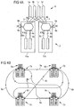
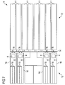
- FIG. 7 shows a plan view of a housing of a modular server system 5.
- a modular server system 5 For example, it is a so-called blade server system which is adapted to accommodate a plurality of server modules 1.
- the server modules 1 accommodated in a front housing section 13 are coupled to a midplane 14 via suitable plug connectors.
- the midplane 14 is a shared circuit board with a variety of electrical connections, which in the exemplary embodiment comprises no active components.
- each I / O module 16 is suitable for receiving in each case two PCI Express expansion cards 19.
- the I / O modules 16 each comprise a module circuit board 17 with a switch element 4 arranged thereon and a connector 18 for the electrical coupling of the module I / O module 16 with the midplane 14.
- I / O modules may be arranged at other locations of the housing.
- further I / O modules for receiving mass storages which do not have the height of a PCI Express expansion card, between or under the power packs of the modular server system 5.
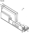
- FIGS. 8A and 8B exemplary embodiments of different I / O modules 16a and 16b are shown.
- the I / O module 16a serves to accommodate two PCI Express expansion cards 19a and 19b.
- a switch element 4 is arranged that received in two PCI Express X16 slots expansion cards 19a and 19b via the connector 18a optionally with different server modules 1 can connect.
- third connections 9 to other I / O modules 16 can also be made via the midplane 14.
- the I / O module 16b serves to accommodate a variety of non-volatile memory devices, which together form a mass storage system.
- the non-volatile memory devices are arranged directly on the module circuit board 17 of the I / O module 16b.
- a switch element 4 is arranged on the printed circuit board 17, so that different data connections can be made by different server modules 1 with the non-volatile memory chips.
- the I / O module 16b has a connector 8 for establishing second connections 8 with server modules 1 and third connections 9 with other I / O modules 16. Other connectors or connections are not required, so that the I / O module 16b is also suitable for installation in inaccessible places of the modular server system 5.
- the architecture described allows a construction of modular server systems 5, in which a multiplicity of different connection topologies between individual server modules 1 and I / O components 2 can be realized.
- 10 different data transmission speeds and modes between individual server modules 1 and thus coupled I / O components 2 can be realized by a suitable choice of the bus widths of compounds 3, 8 and 9 and used components of the connection fabric.
- the architecture has been described with reference to different server systems in which one or two switch elements 4 of a switch arrangement are respectively assigned to the I / O groups 7 and also arranged there. As long as the logical assignment of I / O groups 7 to exactly one server group 6 is maintained, parts of or the entire switch arrangement itself can naturally also be arranged elsewhere on the modular server system, for example on a backplane or midplane 14 or in another component, such as a module to hold a server group.
- the server groups are assigned to exactly one I / O group.
- the corresponding switch elements or arrangements are logically assigned to the server groups and preferably also arranged in spatial proximity to the server modules.
- there is the additional advantage that direct high-speed communication between the server modules of a server group is made possible via the switch arrangement logically assigned to the server group.
- an alternative arrangement on a backplane or midplane or other component such as the I / O modules is possible.
- the mode of operation corresponds to that of the abovementioned exemplary embodiments, wherein in the general case the functions and connections of the respective server and I / O groups are interchanged with each other.
- the embodiments according to the FIGS. 1 to 6 Moreover, a 1: 1 association between server groups 6 on the one hand and I / O groups 7 on the other hand is based, so that There are no further changes except the logical assignment of the switch arrangements to the server groups 6.
- the architectures described allow the creation of redundancy with respect to the server modules 1 used, switch elements 4 and I / O components 2 and connections 3, 8 and 9 as well as the simple switching to redundantly stored spare components.
- the required connection fabric 10 is significantly reduced compared to a complete connection of each server module 1 with each I / O component 2.
Landscapes
- Engineering & Computer Science (AREA)
- General Engineering & Computer Science (AREA)
- Theoretical Computer Science (AREA)
- Physics & Mathematics (AREA)
- Computer Hardware Design (AREA)
- General Physics & Mathematics (AREA)
- Mathematical Physics (AREA)
- Computer Networks & Wireless Communication (AREA)
- Signal Processing (AREA)
- Hardware Redundancy (AREA)
- Bus Control (AREA)
- Multi Processors (AREA)
- Programmable Controllers (AREA)
Description
- Die vorliegende Erfindung betrifft ein modulares Serversystem, umfassend eine Mehrzahl von Servermodulen und eine Mehrzahl von I/O-Komponenten. Die Erfindung betrifft des Weiteren ein I/O-Modul und ein Switching-Verfahren für ein derartiges modulares Serversystem.
- Modulare Serversysteme sind aus dem Stand der Technik bekannt. Beispielsweise sind so genannte Bladeserversysteme bekannt, bei der eine Mehrzahl von Bladeservermodulen, die jeweils wenigstens einen Prozessor und zugehörigen Arbeitsspeicher aufweisen, auf eine gemeinsam genutzte Infrastruktur, insbesondere auf Netzteile, Netzwerkswitches und/oder Massenspeicherkomponenten zugreifen. Die nötigen Verbindungen zwischen den Bladeservermodulen und den gemeinsam genutzten I/O-Komponenten werden dabei in der Regel über eine so genannte Midplane, eine passive, gemeinsam genutzte Leiterplatte des Bladeserversystems, hergestellt.
- Aus dem Stand der Technik sind auch andere, mehr oder weniger modulare Serversysteme bekannt. Beispielsweise sind Servermodule in der Form von Rackservern bekannt, die in ein gemeinsames Rackgehäuse eingeschoben werden und über Kabelverbindungen auf gemeinsame Netzwerkswitches zugreifen.
- Sollen mehrere Servermodule mit einer Mehrzahl von I/O-Komponenten verbunden werden, bestehen für deren datentechnische Kopplung unterschiedliche Möglichkeiten.
- Die
Figur 9A zeigt eine erste Möglichkeit, eine Mehrzahl von I/O-Komponenten mit einer Mehrzahl von Servermodulen zu verbinden. In der in derFigur 9A dargestellten Architektur ist jedem Servermodul 1a bis 1c genau eine I/O-Komponente 2a bis 2c direkt zugeordnet. Die Zuordnung zwischen den Servermodulen 1a bis 1c und den entsprechenden I/O-Komponenten 2a bis 2c erfolgt über elektrische Verbindungen 3a bis 3c eines Serversystems. Wegen der direkten Zuordnung von den I/O-Komponenten 2a bis 2c zu den Servermodulen 1a bis 1c können dazwischen angeordnete Verbindungen 3a bis 3c verhältnismäßig einfach ausgestaltet sein. Insbesondere kann es sich um Leiterbahnen auf einer Backplane oder um andere passive elektrische Verbindungen handeln. - Die in der
Figur 9A dargestellte Architektur besitzt den Nachteil, dass beim Ausfall einer beliebigen I/O-Komponente 2a bis 2c oder Verbindung 3a bis 3c das zugehörige Servermodul 1a bis 1c ihm zugeordnete Aufgaben nicht länger ausführen kann und somit nicht länger zur Verfügung steht. Des Weiteren ist die in derFigur 9A dargestellte Architektur verhältnismäßig ineffizient, da I/O-Komponenten 2a bis 2c, wie beispielsweise Netzwerkkarten, für jedes Servermodul 1a bis 1c getrennt bereitgestellt werden müssen, selbst wenn jeder der Servermodule 1a bis 1c nur eine geringe Bandbreite erfordert, die über eine einzige Netzwerkkarte gemeinsam für alle Servermodule 1a bis 1c bereitgestellt werden könnte. - Die
Figur 9B zeigt eine gegenüber derFigur 9A flexiblere Architektur. Im in derFigur 9B dargestellten Ausführungsbeispiel teilen sich drei Servermodule 1a bis 1c zwei I/O-Komponenten 2a und 2b. Die Verbindungen zwischen den Servermodulen 1a bis 1c und den I/O-Komponenten 2a und 2b werden dabei über ein Switch-Element 4 hergestellt. Dabei verbindet das Switch-Element 4 erste Verbindungen 3a bis 3c zwischen den Servermodulen 1a bis 1c und dem Switch-Element 4 wahlweise mit zweiten Verbindungen 8a und 8b zwischen dem Switch-Element 4 und den I/O-Komponenten 2a bzw. 2b. Auf diese Weise kann, beispielsweise gesteuert durch Adressinformationen in den ausgetauschten Daten, eine wahlfreie Verbindung zwischen einem beliebigen Servermodul 1a bis 1c und einer beliebigen I/O-Komponente 2a oder 2b hergestellt werden. - Die beschriebene Architektur besitzt den Vorteil, dass I/O-Komponenten 2a und 2b gemeinsam von den Servermodulen 1a bis 1c genutzt werden können, was sowohl die Auslastung der einzelnen I/O-Komponenten 2a und 2b als auch deren Verfügbarkeit erhöht. Beispielsweise kann eine einzelne Netzwerkkarte von allen drei Servermodulen 1a bis 1c gemeinsam genutzt werden. Handelt es sich bei den I/O-Komponenten 2a und 2b um vergleichbare Komponenten, beispielsweise um zwei typgleiche Netzwerkkarten, können auch beim Ausfall einer der zwei I/O-Komponenten 2a oder 2b sämtliche Servermodule 1a bis 1c noch erfolgreich Netzwerkverbindungen herstellen.
- Ein Nachteil der in der
Figur 9B dargestellten Architektur besteht darin, dass die Verbindung zwischen den Servermodulen 1a bis 1c einerseits und den I/O-Komponenten 2a und 2b andererseits, auch als so genannte Connection Fabric bezeichnet, verhältnismäßig kompliziert ist. Zum einen ist zum Herstellen der Verbindungen 3 eine aktive Komponente, nämlich das Switch-Element 4 erforderlich, das sowohl die Herstellungskosten als auch die Komplexität des Serversystems erhöht. Wird, wie in derFigur 9B dargestellt, ein einzelnes Switch-Element 4 zur Herstellung sämtlicher Verbindungen verwendet, ergibt sich zusätzlich das Problem eines so genannten "Single Point of Failure", bei dessen Ausfall sämtliche Servermodule 1a bis 1c ausfallen. Darüber hinaus könnte ein derartiges Switch-Element 4 nur in einer zentralen Komponente des modularen Serversystems, beispielsweise einer Backplane oder Midplane angeordnet werden, was deren Kosten erheblich erhöhen würde. - Ein weiteres, gewichtiges Problem der Architektur gemäß
Figur 9B liegt darin, dass insbesondere bei der Verwendung von mehradrigen Verbindungen 3a bis 3e sowie 8a und 8b, wie sie besonders bei besonders leistungsfähigen Bussystemen wie dem so genannten PCI-Express-Standard Verwendung finden, die Anzahl der zu verschaltenden Leitungen sehr stark mit der Anzahl der verwendeten Servermodule und I/O-Komponenten ansteigt. Aus dem in derFigur 9B dargestellten 3x2-Switch-Element 4 wird bei einem Serversystem mit m Servermodulen und n I/O-Komponenten ein in der Herstellung sehr aufwändiges mxn-Switch-Element. Bei wachsender Anzahl von Switchverbindungen zu Servermodulen 1 und I/O-Komponenten 2 wird die Implementierung des Switch-Elementes 3 zunehmend schwierig. Darüber hinaus wird es insbesondere bei den angesprochenen Bussystemen schwierig, sämtliche erforderlichen Leitungen auf einer gemeinsamen Leiterplatte wie insbesondere einer Midplane anzuordnen. Aus diesem Grunde sind derartige Architekturen nur in verhältnismäßig kleinen Serversystemen mit wenigen Komponenten oder für elektrische Verbindungen mit einer oder wenigen Leitungen sinnvoll. - Die
US 2012/0005392 A1 offenbart ein Informationsverarbeitungs-system mit einem Server-Chassis mit - einer Vielzahl von Server-Blades und
- einem ersten PCIe-Switch, der mit den Server-Blades verbunden ist,
- ein I/O-Chassis mit einer Vielzahl von PCIe-Steckplätzen,
- an denen Input-Output-Geräte angeschlossen sind,
- und einen zweiten PCIe-Switch an dem die PCIe-Steckplätze angeschlossen sind,
- wobei der erste PCIe-Switch und der zweite PCIe-Switch durch einen PCIe-Kabel verbunden sind.
- Aus der
US 7 818 387 B1 ist ein kombiniertes Switch- und Serviceprozessormodul und aus der derUS 2006/0031389 A1 ist ein Computersystem und Verfahren zum Konfigurieren eines Speichersystems bekannt. - Aufgabe der vorliegenden Erfindung ist es, eine alternative Architektur für modulare Serversysteme und Verfahren zu deren Betrieb zu beschreiben. Die beschriebenen Lösungen sollen sich insbesondere für hochleistungsfähige Clusteranwendungen und/oder Hochverfügbarkeitssysteme eignen.
- Gemäß einem ersten Aspekt der Erfindung werden modulare Serverarchitekturen beschrieben, die eine Kopplung einer Mehrzahl von Servermodulen mit einer Mehrzahl von I/O-Komponenten gestatten.
- Gemäß einer ersten Ausgestaltung der Erfindung wird ein modulares Serversystem beschrieben, das eine Mehrzahl von Servergruppen umfasst, wobei jede Servergruppe zur Aufnahme einer Mehrzahl von Servermodulen eingerichtet ist. Das Serversystem umfasst weiterhin eine Mehrzahl von I/O-Gruppen, wobei jede I/O-Gruppe zur Aufnahme einer Mehrzahl von I/O-Komponenten eingerichtet ist und eine Switch-Anordnung mit mindestens einem Switch-Element aufweist. Dabei ist jede der Mehrzahl von I/O-Gruppen genau einer der Mehrzahl von Servergruppen zugeordnet. Die Switch-Anordnung einer jeden I/O-Gruppe ist mit jedem der Mehrzahl der I/O-Komponenten der I/O-Gruppe und mit jedem der Mehrzahl der Servermodule der der I/O-Gruppe zugeordneten Servergruppe datentechnisch direkt gekoppelt. Darüber hinaus ist die Switch-Anordnung einer jeden I/O-Gruppe mit mindestens einer anderen Switch-Anordnung einer anderen I/O-Gruppe datentechnisch gekoppelt.
- Durch die Aufteilung von Servermodulen und I/O-Komponenten in Servergruppen und I/O-Gruppen sowie die direkte Zuordnung von I/O-Gruppen zu genau einer Servergruppe kann eine modulare, verteilte Switcharchitektur für ein modulares Serversystem implementiert werden. Dabei werden I/O-Komponenten einer I/O-Gruppe über eine Switch-Anordnung mit mindestens einem Switch-Element der I/O-Gruppe auf relativ kurzem Wege mit zugehörigen Servermodulen einer zugehörigen Servergruppe verbunden, so dass eine verhältnismäßig kleine Anzahl von Servermodulen auf eine verhältnismäßig kleine Anzahl von I/O-Komponenten mit hoher Bandbreite und geringer Latenz zugreifen kann. Andere Verbindungen, also auf I/O-Komponenten von I/O-Gruppen, die einer anderen Servergruppe zugeordnet sind, erfolgen dabei über weitere Verbindungen zwischen Switch-Anordnungen beziehungsweise die darin enthaltenen Switch-Elemente.
- Gemäß einer alternativen Ausgestaltung der Erfindung wird ein modulares Serversystem beschrieben, das eine Mehrzahl von Servergruppen umfasst, wobei jede Servergruppe zur Aufnahme einer Mehrzahl von Servermodulen eingerichtet ist und eine Switch-Anordnung mit mindestens einem Switch-Element aufweist. Das Serversystem umfasst weiterhin eine Mehrzahl von I/O-Gruppen, wobei jede I/O-Gruppe zur Aufnahme einer Mehrzahl von I/O-Komponenten eingerichtet ist. Dabei ist jede der Mehrzahl von Servergruppen genau einer der Mehrzahl von I/O-Gruppen zugeordnet. Die Switch-Anordnung einer jeden Servergruppe ist mit jedem der Mehrzahl der Servermodule der Servergruppe und mit jedem der Mehrzahl der I/O-Module der der Servergruppe zugeordneten I/O-Gruppe datentechnisch direkt gekoppelt. Darüber hinaus ist die Switch-Anordnung einer jeden Servergruppe mit mindestens einer anderen Switch-Anordnung einer anderen Servergruppe datentechnisch gekoppelt.
- Das modulare Serversystem gemäß der alternativen Ausgestaltung weist im Wesentlichen dieselben Eigenschaften auf wie das der ersten Ausgestaltung, wobei die logische Zuordnung zwischen Servergruppen einerseits und I/O-Gruppen andererseits vertauscht ist.
- Ein Vorteil dieser verteilten Switcharchitekturen liegt darin, dass die Anzahl der Leitungen und somit der Kosten für die so genannte Connection Fabric nicht exponentiell mit der Systemgröße, sondern lediglich mit der Größe der verwendeten Servergruppen und/oder I/O-Gruppen ansteigt. Auf diese Weise können die Komplexität und Kosten des modularen Serversystems reduziert werden, wobei ein hoher Grad an Performance, Verfügbarkeit und Redundanz sichergestellt werden kann.
- Gemäß einer bevorzugten Ausgestaltung werden die Verbindungen zwischen den einzelnen Komponenten über eine gemeinsame Leiterplatte, insbesondere eine Backplane oder eine Midplane des modularen Serversystems hergestellt. Bevorzugt sind auf der gemeinsamen Leiterplatte lediglich passive Komponenten, insbesondere elektrische Verbindungen in der Form von Leiterbahnen zur datentechnischen Kopplung der einzelnen Komponenten aufgebracht.
- Das beschriebene Serversystem eignet sich insbesondere zur datentechnischen Kopplung von Punkt-zu-Punkt-Verbindungen mit einer Mehrzahl von Datenleitungen, wie beispielsweise Verbindungen gemäß dem PCI-Express-Standard.
- Bevorzugt handelt es sich bei den I/O-Komponenten um von einer Mehrzahl von Servermodulen gemeinsam nutzbare Komponenten, beispielsweise Netzwerkkomponenten mit einer Mehrzahl von virtuellen und/oder physikalischen Funktionseinheiten oder um Massenspeicherkomponenten wie sogenannte Solid State Disks (SSD) und Host Bus Adapter (HBA).
- Gemäß einem zweiten Aspekt der Erfindung wird ein I/O-Modul zur Verwendung in einem modularen Serversystem beschrieben. Das I/O-Modul umfasst wenigstens eine Modulleiterplatte, wenigstens einen auf der Modulleiterplatte angeordneten ersten Anschluss für eine erste I/O-Komponente, wenigstens einen auf der Modulleiterplatte angeordneten zweiten Anschluss für eine zweite I/O-Komponente und wenigstens einen auf der Modulleiterplatte angeordneten Steckverbinder zur datentechnischen Kopplung des I/O-Moduls mit einer gemeinsamen Leiterplatte des modularen Serversystems. Auf der Modulleiterplatte ist wenigstens ein Switch-Element zum wahlweisen Herstellen von Verbindungen zwischen einer vorbestimmten Gruppe von Servermodulen des modularen Serversystems, die dem I/O-Modul zugeordnet ist, und der ersten und/oder zweiten I/O-Komponente sowie zum Herstellen von Verbindungen zwischen der vorbestimmten Gruppe von Servermodulen des modularen Serversystems und einem gleichartigen I/O-Modul angeordnet.
- Ein derartiges I/O-Modul mit einem oder mehreren integrierten Switch-Elementen erlaubt den Aufbau von modularen Serversystemen mit einer gemeinsamen, bevorzugt passiven Leiterplatte. Dabei wird das Herstellen von Verbindungen zwischen der ersten und der zweiten I/O-Komponente und einem der I/O-Modul zugeordneten Servergruppe direkt über ein integriertes Switch-Element vorgenommen. Darüber hinaus können mittelbaren Verbindungen mit anderen I/O-Modulen über ein Switch-Element des I/O-Moduls und ein Switch-Element eines gleichartigen, benachbarten I/O-Moduls hergestellt werden.
- Gemäß einem dritten Aspekt der Erfindung wird ein Switching-Verfahren für ein modulares Serversystem beschrieben, bei dem erste Datenverbindungen zwischen einer ersten Komponente eines ersten Typs einer ersten Gruppe von gleichartigen Komponenten, insbesondere zwischen einem Servermodul einer Mehrzahl von Servermodulen einer ersten Servergruppe, mit einer zweiten Komponente eines zweiten Typs einer zweiten Gruppe von gleichartigen Komponenten, insbesondere einer I/O-Komponente einer Mehrzahl von I/O-Komponenten einer ersten I/O-Gruppe, direkt über ein erstes Switch-Element der zweiten Gruppe hergestellt werden. Bei dem Verfahren werden zweite Datenverbindungen zwischen der ersten Komponente der ersten Gruppe mit einer dritten Komponente des zweiten Typs, insbesondere einer I/O-Komponente einer Mehrzahl von I/O-Komponenten einer zweiten I/O-Gruppe, indirekt über das erste Switch-Element der zweiten Gruppe und ein zweites Switch-Element der dritten Gruppe hergestellt.
- Ein solches, verteiltes und gegebenenfalls kaskadierbares Switching-Verfahren erlaubt die bedarfsgerechte und einfache Verbindung einer Vielzahl von Servermodulen mit einer Vielzahl von I/O-Komponenten.
- Weitere vorteilhafte Ausgestaltungen sind in den angehängten Patentansprüchen sowie der nachfolgenden ausführlichen Beschreibung von Ausführungsbeispielen offenbart.
- Die Erfindung ist nach den unabhängigen Ansprüchen definiert. Abhängige Ansprüche stellen weitere Ausführungsformen bereit.
- Die Erfindung wird nachfolgend anhand von Ausführungsbeispielen unter Bezugnahme auf die angehängten Figuren näher erläutert. Darin werden die gleichen Bezugszeichen für gleiche oder gleichartige Komponenten unterschiedlicher Ausführungsbeispiele verwendet. Zudem werden einzelne Instanzen einer Mehrzahl von gleichartigen Komponenten zur besseren Unterscheidung durch das Nachstellen eines Suffixes gekennzeichnet. Sofern auf sämtliche Komponenten der gleichen Art Bezug genommen werden soll, wird auf die Verwendung des Suffixes verzichtet.
- In den Figuren zeigen:
- Figur 1
- ein modulares Serversystem gemäß einer ersten Ausgestaltung der Erfindung,
- Figur 2
- Untergruppen eines Serversystem gemäß einer zweiten Ausgestaltung der Erfindung,
- Figur 3
- das modulares Serversystem gemäß der zweiten Ausgestaltung der Erfindung,
- Figur 4A
- ein Verbindungsdiagramm für eine Untergruppe eines modularen Serversystems,
- Figur 4B
- ein Verbindungsdiagramm zwischen verschiedenen Untergruppen eines modularen Serversystems,
- Figur 5
- ein modulares Serversystem gemäß einer dritten Ausgestaltung der Erfindung,
- Figur 6
- ein modulares Serversystem gemäß einer vierten Ausgestaltung der Erfindung,
- Figur 7
- eine Aufsicht auf ein Gehäuse eines modularen Serversystems,
- Figur 8A
- eine perspektivische Ansicht eines ersten I/O-Moduls,
- Figur 8B
- eine perspektivische Ansicht eines zweiten I/O-Moduls,
- Figur 9A
- eine erste Möglichkeit zur Kopplung einer Mehrzahl von Komponenten eines Serversystems und
- Figur 9B
- eine zweite Möglichkeit zur Kopplung einer Mehrzahl von Komponenten eines Serversystems.
-
Figur 1 zeigt ein modulares Serversystem 5 gemäß einem ersten Ausführungsbeispiel. Das modulare Serversystem 5 umfasst acht Servermodule 1a bis 1h in zwei Servergruppen 6a und 6b. Jede der Servergruppen 6a und 6b umfasst jeweils vier Servermodule 1a bis 1d beziehungsweise 1e bis 1h. Jedes Servermodul 1 umfasst wenigstens einen Prozessor und typischerweise Arbeitsspeicher zum Ausführen von einem oder mehreren auf dem Serversystem 5 ablaufenden Programmen. - Das modulare Serversystem 5 umfasst des Weiteren acht I/O-Komponenten 2a bis 2h, die ebenfalls in zwei I/O-Gruppen 7a und 7b angeordnet sind. Zusätzlich umfasst jede I/O-Gruppe 7a und 7b ein zugehöriges Switch-Element 4a beziehungsweise 4b. Bei den I/O-Komponenten 2 handelt es sich beispielsweise um Netzwerkkarten, Massenspeicher oder sonstige Erweiterungen, auf die die Servermodule 1 bei der Ausführung von Programmen zugreifen können. Im beschriebenen Ausführungsbeispiel handelt es sich insbesondere um I/O-Komponenten zum Anschluss an einen oder mehrere Servermodule 1 über einen PCI-Express-Bus. Bevorzugt unterstützen die I/O-Komponenten ein so genanntes "PCI-Express device sharing", also deren gleichzeitige Verwendung durch mehrere Root-Geräte wie insbesondere Servermodule 1. Bei den Switch-Elementen 4a und 4b handelt es sich um Switch-Elemente zum Verbinden einer Mehrzahl von PCI-Express-Datenleitungen, auch bekannt als PCI-Express Lanes.
- Jeder der Servermodule 1a bis 1d der ersten Servergruppe 6a ist über eine eigene erste Verbindung 3a bis 3d direkt mit dem Switch-Element 4a der ersten I/O-Gruppe 7a verbunden. Darüber hinaus ist jede I/O-Komponente 2a bis 2d der ersten I/O-Gruppe 7a über jeweils eine eigene zweite Verbindung 8a bis 8d direkt mit dem ersten Switch-Element 4a verbunden. In entsprechender Weise sind die Servermodule 1e bis 1h sowie die I/O-Komponenten 2e bis 2h über erste Verbindungen 3e bis 3h beziehungsweise zweite Verbindungen 8e bis 8h mit dem zweiten Switch-Element 4b der zweiten I/O-Gruppe 7b verbunden. Schließlich ist das erste Switch-Element 4a über eine dritte Verbindung 9 mit dem zweiten Switch-Element 4b verbunden. Im Ausführungsbeispiel entsprechen alle Verbindungen 3, 8 und 9 dem PCI-Express-X16 Standard, weisen also jeweils 16 differentielle Datenleitungen zum parallelen Senden und Empfangen von Daten auf. Zusammen stellen die Verbindungen 3a bis 3h, 8a bis 8h und 9 sowie die Switch-Elemente 4a und 4b eine Connection Fabric 10 des modularen Serversystems 5 her, die eine selektive Verbindung eines jeden Servermoduls 1 mit jedem der I/O-Komponenten 2 gestattet. Dabei steht für jede einzelne geschaltete Verbindung innerhalb einer Servergruppe 6 und einer zugehörigen I/O-Gruppe 7 die volle Bandbreite einer PCI-Express-X16 Verbindung zur Verfügung.
- Der in der
Figur 1 dargestellten Architektur liegt die Erkenntnis zugrunde, dass die Zugriffshäufigkeiten, -dauern und -intensitäten zwischen Servermodulen 1 einerseits und I/O-Komponenten 2 andererseits ungleich verteilt sind. Bevorzugt ist das System so konfiguriert, dass auf lokale I/O-Komponenten 2, beispielsweise Massenspeicherkomponenten mit lokalen Arbeitsdaten für eine CPU eines Servermoduls 1, verhältnismäßig häufig zugegriffen wird, während auf andere I/O-Komponenten 2 nur verhältnismäßig selten zugegriffen wird. In anderen Anwendungsszenarien, beispielsweise redundanten Clustersystemen, ist das System so konfiguriert, dass es auf die primären I/O-Komponenten 2 eines Servermoduls 1 verhältnismäßig häufig zugreift, während es lediglich im Fehlerfall einer primären I/O-Komponente 2 auf eine redundant vorgehaltene sekundären I/O-Komponente 2 zugreift. - Vor dem Hintergrund dieser Erkenntnis besitzt die Architektur gemäß
Figur 1 den Vorteil, dass bei entsprechender Verteilung der I/O-Komponenten 2 und Servermodule 1, die Servermodule 1a bis 1d der ersten Servergruppe 6a mit hoher Bandbreite und geringer Latenzzeit über eine dedizierte Datenverbindung auf sämtliche Komponenten 2a bis 2d der ersten I/O-Gruppe 7a zugreifen können. Dabei bleibt der Zugriff auf andere I/O-Komponenten 2e bis 2h der zweiten Servergruppe 7b über die Verbindung 9 im Ausnahmefall möglich, ohne dass hierzu weitere dedizierte Verbindungen zwischen den Servermodulen 1a bis 1d der ersten Servergruppe 6a und dem zweiten Switch-Element 4b erforderlich wären. Stattdessen werden solche Datenverbindungen über eine einzelne oder wenige gemeinsam genutzte dritte Verbindungen 9, beispielsweise im Zeitmultiplex, hergestellt. -
Figur 2 zeigt einen Teil eines modularen Serversystems 5, das insbesondere zur Implementierung von Hochverfügbarkeits-Systemen geeignet ist. In der Konfiguration gemäßFigur 2 greifen vier gleichartige Servermodule 1a bis 1d einer einzelnen Servergruppe 6 auf vier gemeinsam genutzte I/O-Komponenten 2a bis 2d zu. Um eine besonders hohe Verfügbarkeit der I/O-Komponenten 2a bis 2d zu gewährleisten, sind diese in zwei Untergruppen 11a beziehungsweise 11b aufgeteilt. Dabei entsprechen die sekundären I/O-Komponenten 2c und 2d der zweiten Untergruppe 11b funktional den primären I/O-Komponenten 2a und 2b der ersten Untergruppe 11a. Gemeinsam bilden die Untergruppen 11a und 11b eine I/O-Gruppe 7, die der Servergruppe 6 zugeordnet ist. - Zur Gewährleistung der Hochverfügbarkeit ist jeder der Servermodule 1a bis 1d über zwei gesonderte erste Verbindungen 3 jeweils mit einem ersten Switch-Element 4a der ersten Untergruppe 11a beziehungsweise einem zweiten Switch-Element 4b der zweiten Untergruppe 11b verbunden. Die beiden Switch-Elemente 4a und 4b bilden zusammen eine Switch-Anordnung der I/O-Gruppe 7. Innerhalb der ersten Untergruppe 11a und der zweiten Untergruppe 11b sind das erste Switch-Element 4a beziehungsweise das zweite Switch-Element 4b über jeweils eine einzelne zweite Verbindung 8 direkt mit den I/O-Komponenten 2a und 2b beziehungsweise 2c und 2d verbunden. Somit kann auch beim Ausfall eines beliebigen Teils, beispielsweise eines Servermoduls 1, einer I/O-Komponente 2, eines Switch-Elementes 4 oder einer der Verbindungen 3 oder 8 eine Datenverarbeitung fortgeführt werden.
- Dabei ist es nicht erforderlich, über die in der
Figur 2 nur angedeuteten dritten Verbindungen 9 auf benachbarte I/O-Gruppen 7 zuzugreifen. Fällt beispielsweise das erste Switch-Element 4a oder die erste I/O-Komponente 2a aus, kann das erste Servermodul 1a ein durch ihn ausgeführtes Programm unter Verwendung des zweiten Switch-Elementes 4b und der gleichartigen I/O-Komponente 2c fortsetzen. Lediglich wenn mindestens zwei der jeweils zueinander redundanten Komponenten der I/O-Gruppe 7 ausfallen, ist ein Zugriff über die dritten Verbindungen 9 auf Komponenten von benachbarter I/O-Gruppen 7 erforderlich, wie es nachfolgend unter Bezugnahme auf dieFigur 3 beschrieben wird. -
Figur 3 zeigt die Verbindung einer Mehrzahl von Gruppen 7 und Untergruppen 11 gemäßFigur 2 in einem modularen Serversystem 5. Im in derFigur 3 dargestellten Ausführungsbeispiel greifen insgesamt 16 Servermodule 1, die in vier gleich große Servergruppen 6a bis 6d von je vier Servermodulen 1 gegliedert sind, auf insgesamt 16 I/O-Komponenten zu, die ebenfalls in vier I/O-Gruppen 7a bis 7d mit jeweils vier I/O-Komponenten 2 gegliedert sind. Dabei ist jede der I/O-Gruppen 7a bis 7d in eine erste Untergruppe 11a und eine zweite Untergruppe 11b untergliedert, wie dies oben bezüglich derFigur 2 beschrieben ist. - Um auch eine Redundanz bezüglich der Verbindungen zwischen verschiedenen I/O-Gruppen 7 herzustellen, sind beispielsweise zwei gesonderte dritte Verbindungen 9a und 9b zwischen zwei benachbarten I/O-Gruppe 7 vorgesehen. Anstelle der dargestellten zwei Verbindungen 9a und 9b können auch andere Verbindungstopologien Verwendung finden. Die Verbindungen 9a und 9b können beispielsweise über eine gemeinsam genutzte Leiterplatte wie die Backplane des modularen Serversystems 5 bereitgestellt werden. Im Ausführungsbeispiel gemäß der
Figur 3 ist dabei jeweils das Switch-Element 4a der ersten Untergruppe 11a einer jeden I/O-Gruppe 7 mit der oder den Nachbarverbindungen 9a gekoppelt und das Switch-Element 4b der zweiten Untergruppe 11b einer jeden I/O-Gruppe 7 mit der oder den Nachbarverbindungen 9b gekoppelt. Im Ergebnis ergibt sich ein vollständig redundantes modulares Serversystem 5, das einen besonders hohen Grad an Verfügbarkeit, Leistungsfähigkeit und Flexibilität bietet. -
Figur 4A zeigt ein weiteres mögliches Verbindungsschema für zwei Switch-Elemente 4a und 4b einer redundanten I/O-Gruppe 7 mit zwei Untergruppen 11a und 11b. Im Ausführungsbeispiel handelt es sich bei den ersten Verbindungen 3 zwischen den Switch-Elementen 4a oder 4b und einem von insgesamt vier Servermodulen 1a bis 1d einer Servergruppe 6 jeweils um PCI-Express-X8-Verbindungen mit jeweils acht differenziellen Leitungspaaren zum Senden und Empfangen. Die zweiten Verbindungen 8a bis 8d zwischen den Switch-Elementen 4a und 4b und vier I/O-Komponenten 2a bis 2d sind im Ausführungsbeispiel als PCI-Express-X16-Verbindungen mit jeweils 16 differenziellen Leitungspaaren zum Senden und Empfangen ausgeführt. Zusätzlich sind an jedes Switch-Element 4a und 4b zwei dritte Verbindungen 9a und 9b in der Form von PCI-Express-X8-Verbindungen mit jeweils acht differenziellen Leitungspaaren zum Senden und Empfangen vorgesehen. Somit eignen sich beispielsweise bekannte PCI-Express-Switch-Bausteine mit 81 frei konfigurierbaren PCI-Express Lanes. Dabei werden die Anschlüsse für die Verbindungen 3 und 8 jeweils als Endpunkte konfiguriert, während die Anschlüsse für die Verbindungen 9 als Routing-Verbindungen konfiguriert werden. Der verbleibende 81. Anschluss wird in einer Ausgestaltung zu Steuerzwecken genutzt und ist beispielsweise mit anderen Switch-Elementen, einem Systemmanagementbaustein oder einer sonstigen Steuerkomponente des Serversystems gekoppelt. - Durch die unterschiedliche Auslegung der Verbindungen können deren Leistungsfähigkeiten an die Bedürfnisse des modularen Serversystems 5 angepasst werden. Beispielsweise kann eine besonders leistungsfähige I/O-Komponente 2a, wie etwa ein Massenspeichersystem, das von zwei Servermodulen 1a und 1b zeitgleich genutzt wird, über eine zweite Verbindung 8a mit einer höheren Verbindungsgeschwindigkeit als die zwei ersten Verbindungen 3 der Servermodule 1a und 1b an das Switch-Element 4a angebunden werden. Von Vorteil dabei ist, dass die zweiten Verbindungen mit einer hohen Anzahl von Leiterbahnen sich nur innerhalb der I/O-Gruppe 7 erstrecken, während die ersten Verbindungen 3 und die dritten Verbindungen 9 eine geringere Anzahl an Leiterbahnen erfordern.
- Da jeder der Servermodule 1a bis 1d der Servergruppe 6 bereits direkt mit beiden Switch-Elementen 4a und 4b gekoppelt ist, kann auf eine direkte Querverbindung zwischen dem ersten Switch-Element 4a und zweiten Switch-Element 4b verzichtet werden. Stattdessen werden die Switch-Elemente 4a und 4b mit Switch-Elementen 4 anderer I/O-Gruppen 7 verbunden, um eine Connection Fabric 10 herzustellen, die beispielsweise zur Implementierung eines modularen Serversystems 5 mit 16 Servermodulen 1 und 16 I/O-Komponenten 2 gemäß
Figur 4B geeignet ist. - Neben der Möglichkeit, eine verteilte, modulare Connection Fabric 10 aufzubauen, bietet die beschriebene modulare Serverarchitektur auch die Möglichkeit, unterschiedliche Verbindungstopologien in einem einheitlichen modularen Serversystem zu implementieren. Dies ist beispielsweise in den
Figuren 5 und6 dargestellt. - In der in
Figur 5 dargestellten Topologie wurden anstelle von Switch-Elementen, Retimer-Bausteine 12a und 12b in zwei I/O-Gruppen 7a und 7b mit jeweils acht I/O-Komponenten 2 eingesetzt. Im Ergebnis kann jeder von 16 Servermodulen 1 somit nur auf eine einzelne I/O-Komponente 2, im Ausführungsbeispiel gemäßFigur 6 beispielsweise eine so genannte Solid State Disc (SSD) zugreifen. Der Zugriff auf benachbarten I/O-Komponenten entweder derselben I/O-Gruppe 7 oder der benachbarten I/O-Gruppen 7 ist dagegen nicht möglich. - Es ist zu beachten, dass die ersten Verbindungen 3 und die zweiten Verbindungen 8 genau den Verbindungen entsprechen, die zur Herstellung einer verteilten modularen Switcharchitektur benötigt werden. Diese Tatsache ermöglicht die besonders einfache und kostengünstige Ausführung unterschiedlicher Konfigurationen mit denselben Basiskomponenten. Insbesondere ist es nicht erforderlich, unterschiedliche Servermodule 1, I/O-Komponenten 2, Backplanes oder Midplanes zur Verwirklichung unterschiedlicher Systemarchitekturen vorzusehen. Lediglich die aktiven Komponenten und eingesetzte interne Verbindungsmatrix der I/O-Gruppen 7 muss entsprechend angepasst werden.
- Somit kann entsprechend den Anforderungen eines Kunden, durch bloßen Ersatz eines eingesetzten I/O-Moduls, das die Funktionselemente einer I/O-Gruppe 7 beinhaltet, die Verbindungstopologie des modularen Serversystems 5 geändert werden. Beispielsweise können für einen Kunden, der auf eine Hochverfügbarkeit der I/O-Komponenten 2 verzichten möchte, verhältnismäßig kostengünstige Retimer-Bausteine 12 anstelle von Switch-Elementen 4 eingesetzt werden.
- Selbstverständlich ist auch ein Mischbetrieb beider Topologien möglich, wie dies beispielsweise in der
Figur 6 dargestellt ist. Das darin dargestellte modulare Serversystem 5 umfasst zwei Servergruppen 6a und 6b und vier I/O-Gruppen 7a bis 7d. Die I/O-Komponenten 2 der ersten und vierten I/O-Gruppe 7a bzw. 7d sind über Retimer-Bausteine 12a bzw. 12b direkt mit jeweils einem der Servermodule 1 verbunden. - Beispielsweise handelt es sich um Coprozessorkarten, die einem Prozessor eines der Servermodule 1 jeweils als nicht teilbare Ressource zugeordnet sind. Die übrigen I/O-Komponenten 2, beispielsweise Netzwerkkarten mit mehreren logischen oder physikalischen Netzwerkschnittstellen, sind wie unter Bezugnahme auf die
Figuren 2 und3 beschrieben über Switch-Elemente 4a bis 4d redundant mit sämtlichen Servermodulen 1 des modularen Serversystems 5 verbunden. Dabei sind sie wie oben beschrieben in jeweils zwei redundante Untergruppen 11a und 11b je I/O-Gruppe 7 aufgeteilt. - Auch bei dieser Konfiguration ist es nicht erforderlich, die beispielsweise auf einer Backplane vorgesehenen Verbindungen zu ändern. Im Ausführungsbeispiel werden die Verbindungen 3 zwischen Servermodulen 1 und Retimer-Bausteinen 12 über PCI-Express-X16 Verbindungen hergestellt. Die Verbindungen zwischen einem Servermodul 1 und je einem der zwei direkt damit gekoppelten Switch-Elementen 4 wird über PCI-Express-X8 Verbindungen hergestellt. Im Ergebnis ergibt sich somit für jede der I/O-Gruppen und unabhängig von deren interner Topologie ein Bedarf für 16 PCI-Express Lanes je Servermodul 1 bzw. 64 PCI-Epress-Lanes je I/O-Gruppe 7.
-
Figur 7 zeigt eine Aufsicht auf ein Gehäuse eines modularen Serversystems 5. Beispielsweise handelt es sich um ein so genanntes Blade-Serversystem das zur Aufnahme einer Mehrzahl von Servermodulen 1 eingerichtet ist. - Die in einem vorderen Gehäuseabschnitt 13 aufgenommenen Servermodule 1 werden über geeignete Steckverbinder mit einer Midplane 14 gekoppelt. Bei der Midplane 14 handelt es sich um eine gemeinsam genutzte Leiterplatte mit einer Vielzahl von elektrischen Verbindungen, die im Ausführungsbeispiel keine aktiven Komponenten umfasst.
- Auf der Rückseite der Midplane 14 sind Steckverbinder zum Anschluss von weiteren Komponenten des Bladeserversystems in einem hinteren Gehäuseabschnitt 15 angeordnet. Neben allgemeinen Infrastrukturkomponenten, wie insbesondere Netzteilen und Systemlüftern, sind in dem modularen Serversystem 5 gemäß
Figur 7 auch vier I/O-Module 16 angeordnet, die zur Aufnahme von I/O-Komponenten 2 geeignet sind. Beispielsweise eignet sich jedes I/O-Modul 16 zur Aufnahme von jeweils zwei PCI-Express-Erweiterungskarten 19. Die I/O-Module 16 umfassen jeweils eine Modulleiterplatte 17 mit einem darauf angeordneten Switch-Element 4 sowie einem Steckverbinder 18 zur elektrischen Kopplung des I/O-Moduls 16 mit der Midplane 14. - Zusätzlich können weitere I/O-Module, gegebenenfalls mit abweichendem Formfaktor, an anderen Stellen des Gehäuses angeordnet sein. Beispielsweise ist es möglich, weitere I/O-Module zur Aufnahme von Massenspeichern, die nicht die Bauhöhe einer PCI-Express-Erweiterungskarte aufweisen, zwischen oder unter den Netzteilen des modularen Serversystems 5 anzuordnen.
- In den
Figuren 8A und8B sind beispielhafte Ausgestaltungen von unterschiedlichen I/O-Modulen 16a und 16b dargestellt. - Das I/O-Modul 16a gemäß
Figur 8A dient beispielsweise zur Aufnahme von zwei PCI-Express-Erweiterungskarten 19a und 19b. Auf der Leiterplatte 17 ist ein Switch-Element 4 angeordnet, dass in zwei PCI-Express-X16-Steckplätzen aufgenommene Erweiterungskarten 19a und 19b über den Steckverbinder 18a wahlweise mit unterschiedlichen Servermodulen 1 verbinden kann. Über einen weiteren Steckverbinder 18b können über die Midplane 14 auch dritte Verbindungen 9 zu anderen I/O-Modulen 16 hergestellt werden. - Das I/O-Modul 16b gemäß
Figur 8B dient zur Aufnahme einer Vielzahl von nichtflüchtigen Speicherbausteinen, die gemeinsam ein Massenspeichersystem bilden. In der inFigur 8B dargestellten Ausgestaltung sind die nichtflüchtigen Speicherbausteine unmittelbar auf der Modulleiterplatte 17 des I/O-Moduls 16b angeordnet. Daneben ist auf der Leiterplatte 17 auch ein Switch-Element 4 angeordnet, so dass unterschiedliche Datenverbindungen von unterschiedlichen Servermodulen 1 mit den nicht flüchtigen Speicherbausteinen hergestellt werden können. Das I/O-Modul 16b weist einen Steckverbinder 8 zum Herstellen von zweiten Verbindungen 8 mit Servermodulen 1 und dritten Verbindungen 9 mit anderen I/O-Modulen 16 auf. Weitere Steckverbinder oder Anschlüsse sind nicht erforderlich, so dass sich das I/O-Modul 16b auch zum Einbau an unzugänglichen Stellen des modularen Serversystems 5 eignet. - Die beschriebene Architektur erlaubt einen Aufbau von modularen Serversystemen 5, bei denen eine Vielzahl unterschiedlicher Verbindungstopologien zwischen einzelnen Servermodulen 1 und I/O-Komponenten 2 verwirklicht werden können. Dabei können durch geeignete Wahl der Busbreiten von Verbindungen 3, 8 und 9 sowie eingesetzten Komponenten der Connection Fabric 10 unterschiedliche Datenübertragungsgeschwindigkeiten und -modi zwischen einzelnen Servermodulen 1 und damit gekoppelten I/O-Komponenten 2 verwirklicht werden.
- Die Architektur wurde unter Bezugnahme auf unterschiedliche Serversysteme beschrieben, bei denen ein oder zwei Switch-Elemente 4 einer Switch-Anordnung jeweils den I/O-Gruppen 7 zugeordnet und auch dort angeordnet sind. Solange die logische Zuordnung von I/O-Gruppen 7 zu genau einer Servergruppe 6 beibehalten wird, können Teile der oder die gesamte Switch-Anordnung selbst natürlich auch an anderer Stelle des modularen Serversystems angeordnet werden, zum Beispiel auf einer Back- oder Midplane 14 oder in einer anderen Komponente wie einem Modul zur Aufnahme einer Servergruppe.
- Darüber hinaus ist aber auch möglich, die gesamte Architektur umzukehren, da heißt die Servergruppen jeweils genau einer I/O-Gruppe zuzuordnen. In diesem Fall sind die entsprechenden Switch-Elemente bzw. Anordnungen logisch den Servergruppen zugeordnet und bevorzugt auch in räumlicher Nähe zu den Servermodulen angeordnet. In diesem Fall ergibt sich der zusätzlich Vorteil, dass eine direkte Hochgeschwindigkeitskommunikation zwischen den Servermodulen einer Servergruppe über die logisch der Servergruppe zugeordnete Switch-Anordnung ermöglicht wird. Auch hier ist alternativ eine Anordnung auf einer Back- oder Midplane oder einer anderen Komponente wie den I/O-Modulen möglich.
- Die Funktionsweise entspricht der der oben genannten Ausführungsbeispiele, wobei im allgemeinen Fall die Funktionen und Verbindungen der jeweiligen Server- und I/O-Gruppen jeweils miteinander vertauscht werden. Den Ausführungsbeispielen gemäß den
Figuren 1 bis 6 liegt überdies eine 1:1-Zuordnung zwischen Servergruppen 6 einerseits und I/O-Gruppen 7 andererseits zugrunde, so dass sich außer der logischen Zuordnung der Switch-Anordnungen zu den Servergruppen 6 keine weiteren Änderungen ergeben. - Die beschriebenen Architekturen erlauben die Schaffung einer Redundanz bezüglich der verwendeten Servermodule 1, Switch-Elemente 4 und I/O-Komponenten 2 und Verbindungen 3, 8 und 9 sowie die einfache Umschaltung auf redundant vorgehaltene Ersatzkomponenten. Gleichzeitig wird die erforderliche Connection Fabric 10 gegenüber einer vollständigen Verknüpfung von jedem Servermodul 1 mit jeder I/O-Komponente 2 deutlich reduziert.
- Somit bieten die beschriebenen Architekturen unter anderem folgende Vorteile:
- Einen optimierten gemeinsamen Zugriff auf I/O-Komponenten 2 einer lokalen I/O-Gruppe 7 durch Servermodule 1 einer Servergruppe 6.
- Eine reduzierte Komplexität einer Midplane 14.
- Die Möglichkeit, auch I/O-Komponenten 2 von entfernten I/O-Gruppen 7 zu nutzen.
- Die Schaffung einer Redundanz bezüglich der Verbindungen 3, 8 und 9 zwischen Servermodulen 1 und I/O-Komponenten 2.
- Eine lineare Skalierung der Komplexität und Kosten der Connection Fabric 10 in Abhängigkeit der Bestückung des modularen Serversystems 5.
- Die Möglichkeit der Kombination unterschiedlicher Verbindungstopographien in einem einzigen modularen Serversystem 5.
- Die Möglichkeit zur Schaffung von Hotplug-Fähigkeiten für die eingesetzten I/O-Komponenten 2 und/oder I/O-Module 16.
- Die Möglichkeit zur Schaffung einer Transparenz bezüglich der auf den Servermodulen ablaufenden Betriebssystemen und Programmen durch die Verlagerung der Switching und Redunanz-Funktionalität in die PCI-Express Connection Fabric 10.
- Die in den Ausführungsbeispielen gezeigten und oben beschriebenen Einzelheiten können in vielfältiger Weise miteinander kombiniert werden, um die jeweils beschriebenen Vorteile und Wirkungen zu erzielen.
-
- 1
- Servermodul
- 2
- I/O-Komponente
- 3
- erste Verbindung
- 4
- Switch-Element
- 5
- modulares Serversystem
- 6
- Servergruppe
- 7
- I/O-Gruppe
- 8
- zweite Verbindung
- 9
- dritte Verbindung
- 10
- Connection Fabric
- 11
- Untergruppe
- 12
- Retimer-Baustein
- 13
- vorderer Gehäuseabschnitt
- 14
- Midplane
- 15
- hinterer Gehäuseabschnitt
- 16
- I/O-Modul
- 17
- Modulleiterplatte
- 18
- Steckverbinder
- 19
- PCI-Express-Erweiterungskarte
Claims (12)
- Modulares Serversystem (5), umfassend- eine Mehrzahl von Servergruppen (6), wobei jede Servergruppe (6) zur Aufnahme einer Mehrzahl von Servermodulen (1) eingerichtet ist, und- eine Mehrzahl von I/O-Gruppen (7), wobei jede I/O-Gruppe (7) zur Aufnahme einer Mehrzahl von I/O-Komponenten (2) eingerichtet ist und eine Switch-Anordnung mit mindestens einem Switch-Element (4) aufweist,wobei- jede der Mehrzahl von I/O-Gruppen (7) genau einer der Mehrzahl von Servergruppen (6) zugeordnet ist,- die Switch-Anordnung einer jeden I/O-Gruppe (7) mit jedem der Mehrzahl der I/O-Komponenten (2) der I/O-Gruppe (7) datentechnisch direkt gekoppelt ist,- die Switch-Anordnung einer jeden I/O-Gruppe (7) mit jedem der Mehrzahl der Servermodule (1) der der I/O-Gruppe (7) zugeordneten Servergruppe (6) datentechnisch direkt gekoppelt ist, und- die Switch-Anordnung einer jeden I/O-Gruppe (7) mit mindestens einer anderen Switch-Anordnung einer anderen I/O-Gruppe (7) datentechnisch gekoppelt ist.
- Modulares Serversystem (5) nach Anspruch 1, bei dem wenigstens eine erste I/O-Gruppe (7a) der Mehrzahl von I/O-Gruppen (7) wenigstens eine erste Untergruppe (11a) mit einem ersten Switch-Element (4a) und eine zweite Untergruppe (11b) mit einem zweiten Switch-Element (4b) umfasst, das erste Switch-Element (4a) mit jedem Servermodul (1) einer der ersten I/O-Gruppe (7a) zugeordneten ersten Servergruppe (6a) datentechnisch direkt gekoppelt ist und das zweite Switch-Element (4b) mit jedem Servermodul (1) der ersten Servergruppe (6a) datentechnisch direkt gekoppelt ist.
- Modulares Serversystem (5), umfassend- eine Mehrzahl von Servergruppen (6), wobei jede Servergruppe (6) zur Aufnahme einer Mehrzahl von Servermodulen (1) eingerichtet ist und eine Switch-Anordnung mit mindestens einem Switch-Element (4) aufweist, und- eine Mehrzahl von I/O-Gruppen (7), wobei jede I/O-Gruppe (7) zur Aufnahme einer Mehrzahl von I/O-Komponenten (2) eingerichtet ist,wobei- jede der Mehrzahl von Servergruppen (6) genau einer der Mehrzahl von I/O-Gruppen (7) von zugeordnet ist,- die Switch-Anordnung einer jeden Servergruppe (6) mit jedem der Mehrzahl der Servermodule (1) der Servergruppe (6) datentechnisch direkt gekoppelt ist,- die Switch-Anordnung einer jeden Servergruppe (6) mit jedem der Mehrzahl der I/O-Komponenten (2) der der Servergruppe (6) zugeordneten I/O-Gruppe (7) datentechnisch direkt gekoppelt ist, und- die Switch-Anordnung einer jeden Servergruppe (6) mit mindestens einer anderen Switch-Anordnung einer anderen Servergruppe (6) datentechnisch gekoppelt ist.
- Modulares Serversystem (5) nach einem der Ansprüche 1 bis 3, weiter aufweisend wenigstens eine gemeinsame Leiterplatte, insbesondere eine Backplane oder Midplane (14), mit einer Mehrzahl von ersten elektrischen Verbindungen (3) zur datentechnischen Kopplung der Servergruppen (6) mit den jeweils zugeordneten I/O-Gruppen (7).
- Modulares Serversystem (5) nach Anspruch 4, bei dem die wenigstens eine gemeinsame Leiterplatte eine Mehrzahl von weiteren elektrischen Verbindungen (9) zur datentechnischen Kopplung von Switch-Anordnungen untereinander aufweist.
- Modulares Serversystem (5) nach einem der Ansprüche 1 bis 5, bei dem die datentechnische Kopplung über Punkt-zu-Punkt-Verbindungen (3, 8, 9) mit einer Mehrzahl von Datenleitungen, insbesondere gemäß dem PCI-Express-Standard, hergestellt wird.
- Modulares Serversystem (5) nach einem der Ansprüche 1 bis 6, bei dem wenigstens eine erste I/O-Komponente der Mehrzahl von I/O-Komponenten (2) von einer Mehrzahl von Servermodulen (1) gemeinsam nutzbar ist, wobei es sich bei der ersten I/O-Komponenten (2) insbesondere um eine Netzwerkkomponente mit einer Mehrzahl von Funktionseinheiten oder um eine Massenspeicherkomponente handelt.
- Modulares Serversystem,(5) nach einem der Ansprüche 1 bis 7, bei dem die Mehrzahl von I/O-Komponenten (2) mindestens einer ersten I/O-Gruppe (7a) der Mehrzahl von I/O-Gruppen (7) und/oder die Mehrzahl von Servermodulen (1) wenigstens einer zugeordneten ersten Servergruppe (6a) der Mehrzahl von Servergruppen (6) ein redundantes System bilden, so dass beim Ausfall einer der I/O-Komponenten (2) der ersten I/O-Gruppe (7a) und/oder beim Ausfall einer der Servermodule (1) der ersten Servergruppe (6a) die verbleibenden I/O-Komponenten (2) der ersten I/O-Gruppe (7a) und die verbleibenden Servermodule (1) der ersten Servergruppe (6a) die Funktion der ausgefallenen Komponenten übernehmen können.
- I/O-Modul (16) zur Verwendung in einem modularen Serversystem (5) nach einem der Ansprüche 1 bis 8, umfassend:- wenigstens eine Modulleiterplatte (17),- wenigstens einen auf der Modulleiterplatte (17) angeordneten ersten Anschluss für eine erste I/O-Komponente (2a),- wenigstens einen auf der Modulleiterplatte (17) angeordneten zweiten Anschluss für eine zweite I/O-Komponente (2b),- wenigstens einen auf der Modulleiterplatte angeordneten Steckverbinder (18) zur datentechnischen Kopplung des I/O-Moduls (16) mit einer gemeinsamen Leiterplatte des modularen Serversystems (5), und- wenigstens ein auf der Modulleiterplatte (17) angeordnetes Switch-Element (4) zur wahlweisen Herstellung von Datenverbindungen zwischen einer vorbestimmten Gruppe (6) von Servermodulen (1) des modularen Serversystems (5), die dem I/O-Modul (16) zugeordnet ist, und.der ersten und/oder zweiten I/O-Komponente (2a, 2b) sowie zwischen der vorbestimmten Gruppe (6) von Servermodulen (1) des modularen Serversystems (5) und einem Switch-Element (4) eines gleichartigen I/O-Moduls (16).
- Switching-Verfahren für ein modulares Serversystem (5),- bei dem erste Datenverbindungen zwischen einer ersten Komponente eines ersten Typs einer ersten Gruppe von gleichartigen Komponenten, insbesondere zwischen einem Servermodul (1) einer Mehrzahl von Servermodulen einer ersten Servergruppe (6), mit einer zweiten Komponente eines zweiten Typs einer zweiten Gruppe von gleichartigen Komponenten, insbesondere einer I/O-Komponente (2) einer Mehrzahl von I/O-Komponenten einer ersten I/O-Gruppe (7), direkt über ein erstes Switch-Element (4) der zweiten Gruppe hergestellt werden und- bei dem zweite Datenverbindungen zwischen der ersten Komponente der ersten Gruppe mit einer dritten Komponente des zweiten Typs, insbesondere einer I/O-Komponente (2) einer Mehrzahl von I/O-Komponenten einer zweiten I/O-Gruppe (7), indirekt über das erste Switch-Element (4) und ein zweites Switch-Element (4) der dritten Gruppe hergestellt werden.
- Switching-Verfahren nach Anspruch 10, bei dem die erste Datenverbindung eine höhere Datenübertragungsrate und/oder eine geringere Latenzzeit aufweisen als die zweiten Datenverbindungen.
- Switching-Verfahren nach Anspruch 10 oder 11, bei dem die ersten Datenverbindungen von der ersten Komponente der ersten Gruppe und der zweiten Komponente der zweiten Gruppe exklusiv nutzbar sind und bei dem die zweiten Datenverbindungen von einer Mehrzahl von Komponenten der ersten Gruppe und/oder einer Mehrzahl von drittenKomponenten (2) der dritten Gruppe (7) über ein Multiplexverfahren gemeinsam nutzbar sind
Applications Claiming Priority (2)
| Application Number | Priority Date | Filing Date | Title |
|---|---|---|---|
| DE102012102198A DE102012102198A1 (de) | 2012-03-15 | 2012-03-15 | Modulares Serversystem, I/O-Modul und Switching-Verfahren |
| PCT/EP2013/051947 WO2013135424A2 (de) | 2012-03-15 | 2013-01-31 | Modulares serversystem, i/o-modul und switching-verfahren |
Publications (2)
| Publication Number | Publication Date |
|---|---|
| EP2825968A2 EP2825968A2 (de) | 2015-01-21 |
| EP2825968B1 true EP2825968B1 (de) | 2017-08-16 |
Family
ID=47715993
Family Applications (1)
| Application Number | Title | Priority Date | Filing Date |
|---|---|---|---|
| EP13704380.8A Not-in-force EP2825968B1 (de) | 2012-03-15 | 2013-01-31 | Modulares serversystem, i/o-modul und switching-verfahren |
Country Status (5)
| Country | Link |
|---|---|
| US (1) | US20150058518A1 (de) |
| EP (1) | EP2825968B1 (de) |
| JP (1) | JP6042914B2 (de) |
| DE (1) | DE102012102198A1 (de) |
| WO (1) | WO2013135424A2 (de) |
Families Citing this family (6)
| Publication number | Priority date | Publication date | Assignee | Title |
|---|---|---|---|---|
| JP6200707B2 (ja) * | 2013-06-28 | 2017-09-20 | 富士通株式会社 | スイッチおよび制御方法 |
| CN105676972B (zh) * | 2015-07-22 | 2020-11-13 | 加弘科技咨询(上海)有限公司 | 电子装置 |
| US9568961B1 (en) * | 2015-07-22 | 2017-02-14 | Celestica Technology Consultancy (Shanghai) Co. Ltd | Electronic apparatus |
| US10666540B2 (en) * | 2017-07-17 | 2020-05-26 | International Business Machines Corporation | Dynamic time-domain reflectometry analysis for field replaceable unit isolation in a running system |
| US12259835B2 (en) | 2020-11-16 | 2025-03-25 | Intel Corporation | Disaggregation of computing devices using enhanced retimers with circuit switching |
| NL2029396B1 (en) * | 2020-11-16 | 2022-11-09 | Intel Corp | Disaggregation of computing devices using enhanced retimers with circuit switching |
Family Cites Families (23)
| Publication number | Priority date | Publication date | Assignee | Title |
|---|---|---|---|---|
| US6308289B1 (en) * | 1998-10-01 | 2001-10-23 | International Business Machines Corporation | Method and system for environmental sensing and control within a computer system |
| US7818387B1 (en) * | 2004-02-09 | 2010-10-19 | Oracle America, Inc. | Switch |
| JP4377279B2 (ja) * | 2004-05-06 | 2009-12-02 | 株式会社日立製作所 | ストレージシステム、コンピュータシステム、およびストレージシステムの設定方法 |
| JP2005326911A (ja) * | 2004-05-12 | 2005-11-24 | Hitachi Ltd | San管理方法 |
| US20060059294A1 (en) * | 2004-09-16 | 2006-03-16 | Smith Kevin T | Expandable bus topology for peripheral devices of straddle vehicles |
| US7890669B2 (en) * | 2005-11-25 | 2011-02-15 | Hitachi, Ltd. | Computer system for sharing I/O device |
| TWI311714B (en) * | 2006-09-08 | 2009-07-01 | Quanta Comp Inc | Method for enabling two sets of i/o peripherals to operate the same host in certralized computer system |
| US8005999B1 (en) * | 2007-09-27 | 2011-08-23 | Emc Corporation | Data storage system with PCI-E extended reach capability |
| US7783818B1 (en) * | 2007-12-28 | 2010-08-24 | Emc Corporation | Modularized interconnect between root complexes and I/O modules |
| JP5074274B2 (ja) * | 2008-04-16 | 2012-11-14 | 株式会社日立製作所 | 計算機システム及び通信経路の監視方法 |
| JP4571203B2 (ja) * | 2008-05-09 | 2010-10-27 | 株式会社日立製作所 | 情報処理システムにおける管理サーバ、及びクラスタ管理方法 |
| JP2009282917A (ja) * | 2008-05-26 | 2009-12-03 | Hitachi Ltd | サーバ間通信機構及びコンピュータシステム |
| DE102008046577A1 (de) * | 2008-09-10 | 2010-03-11 | Fujitsu Siemens Computers Gmbh | Anschlussvorrichtung zum Anschluss einer Mehrzahl von Peripheriegeräten und Betriebsverfahren |
| WO2010084529A1 (ja) * | 2009-01-23 | 2010-07-29 | 株式会社日立製作所 | 情報処理システム |
| JP2010224744A (ja) * | 2009-03-23 | 2010-10-07 | Nec Corp | セッション管理装置および方法 |
| WO2011043769A1 (en) * | 2009-10-07 | 2011-04-14 | Hewlett-Packard Development Company, L.P. | Notification protocol based endpoint caching of host memory |
| JP5253353B2 (ja) * | 2009-10-26 | 2013-07-31 | 株式会社日立製作所 | 情報処理システム、及びストレージ監視サーバの管理方法 |
| JP2011164686A (ja) * | 2010-02-04 | 2011-08-25 | Ricoh Co Ltd | 情報処理装置、画像処理装置、ログインの認証方法、プログラム及び記録媒体 |
| WO2011151930A1 (ja) * | 2010-06-01 | 2011-12-08 | 株式会社日立製作所 | I/oデバイス管理方法、計算機システム及びi/oデバイス管理プログラム |
| US8055934B1 (en) * | 2010-06-22 | 2011-11-08 | International Business Machines Corporation | Error routing in a multi-root communication fabric |
| US20120137085A1 (en) * | 2010-11-25 | 2012-05-31 | Hitachi, Ltd. | Computer system and its control method |
| JP5399570B2 (ja) * | 2010-11-29 | 2014-01-29 | 株式会社日立製作所 | 計算機システム、それに使用されるスイッチ及びパケット転送制御方法 |
| US9612989B2 (en) * | 2010-12-24 | 2017-04-04 | Hitachi, Ltd. | Computer system and routing control method |
-
2012
- 2012-03-15 DE DE102012102198A patent/DE102012102198A1/de not_active Withdrawn
-
2013
- 2013-01-31 WO PCT/EP2013/051947 patent/WO2013135424A2/de not_active Ceased
- 2013-01-31 US US14/385,302 patent/US20150058518A1/en not_active Abandoned
- 2013-01-31 EP EP13704380.8A patent/EP2825968B1/de not_active Not-in-force
- 2013-01-31 JP JP2014561336A patent/JP6042914B2/ja not_active Expired - Fee Related
Also Published As
| Publication number | Publication date |
|---|---|
| WO2013135424A3 (de) | 2013-11-14 |
| DE102012102198A1 (de) | 2013-09-19 |
| JP6042914B2 (ja) | 2016-12-14 |
| WO2013135424A2 (de) | 2013-09-19 |
| US20150058518A1 (en) | 2015-02-26 |
| JP2015516617A (ja) | 2015-06-11 |
| EP2825968A2 (de) | 2015-01-21 |
Similar Documents
| Publication | Publication Date | Title |
|---|---|---|
| DE69725519T2 (de) | Verbindung eines Doppelspannungsmoduls | |
| DE102004053801B4 (de) | Dynamische Rekonfiguration von PCI-Expresslinks | |
| DE69620497T2 (de) | Verbindungsnetzwerk für ein Datenverarbeitungssystem mit mehreren Knoten | |
| DE69636663T2 (de) | System und Verfahren zur Zugriffsverteilung von Mehrfachspeichermatrixen zwischen Mehrfachwirtrechnersystemen | |
| DE102005055185B4 (de) | Halbleiterspeichermodul | |
| DE602004012633T2 (de) | Vorrichtung und Verfahren zur Integration von Mehrserverplattformen | |
| DE10208726B4 (de) | Signalverarbeitungssystem für die Verwendung mit einem oder mehreren Modulen | |
| DE112017003699T5 (de) | Speicher-Sled für Daten-Center-bezogene Abwendungen | |
| EP2880534B1 (de) | Hochverfügbares rechnersystem, arbeitsverfahren und dessen verwendung | |
| DE102014112943B4 (de) | Modulares Computersystem und Servermodul | |
| DE10121901A1 (de) | Speichersystem und hierfür verwendbares Speichermodul | |
| DE102012210582A1 (de) | Verringern der Auswirkung des Ausfalls einer Vermittlungsstelle in einem Schaltnetzwerk mittels Schaltkarten | |
| DE112007002211T5 (de) | Vorrichtung und Verfahren zum Verbinden von SAS RAID Controller-Vorrichtungs-Kanälen über redundante Speichersubsysteme hinweg | |
| EP2825968A2 (de) | Modulares serversystem, i/o-modul und switching-verfahren | |
| DE102014112942B3 (de) | Modulares Computersystem, Servermodul und Rackanordnung | |
| DE102004024130B4 (de) | Speichersystem und Verfahren zum Betrieb eines Speichersystems | |
| DE102018005759A1 (de) | Verbinden von beschleunigerressourcen unter verwendung einesswitches | |
| DE102008046577A1 (de) | Anschlussvorrichtung zum Anschluss einer Mehrzahl von Peripheriegeräten und Betriebsverfahren | |
| DE112020005819T5 (de) | Virtuelle einschübe in einem server | |
| DE102005025947A1 (de) | Hierarchisches Modul | |
| DE10214701A1 (de) | ATA- und SATA-gemässer Controller | |
| WO2007006267A1 (de) | Steckerplatine zum einsatz in einem einschubrahmen für peripheriegeräte | |
| DE60126158T2 (de) | Serverlets mit hoher dichte mittels hochgeschwindigkeits-datenbus | |
| DE69802206T2 (de) | Verbindungsschaltung für elektronische module | |
| DE112017004036T5 (de) | Massenspeichereinheiten-pakete und softwaredefinierte anordnungen von derartigen paketen |
Legal Events
| Date | Code | Title | Description |
|---|---|---|---|
| PUAI | Public reference made under article 153(3) epc to a published international application that has entered the european phase |
Free format text: ORIGINAL CODE: 0009012 |
|
| 17P | Request for examination filed |
Effective date: 20140912 |
|
| AK | Designated contracting states |
Kind code of ref document: A2 Designated state(s): AL AT BE BG CH CY CZ DE DK EE ES FI FR GB GR HR HU IE IS IT LI LT LU LV MC MK MT NL NO PL PT RO RS SE SI SK SM TR |
|
| AX | Request for extension of the european patent |
Extension state: BA ME |
|
| DAX | Request for extension of the european patent (deleted) | ||
| GRAP | Despatch of communication of intention to grant a patent |
Free format text: ORIGINAL CODE: EPIDOSNIGR1 |
|
| INTG | Intention to grant announced |
Effective date: 20170324 |
|
| RAP1 | Party data changed (applicant data changed or rights of an application transferred) |
Owner name: FUJITSU LIMITED |
|
| GRAS | Grant fee paid |
Free format text: ORIGINAL CODE: EPIDOSNIGR3 |
|
| GRAA | (expected) grant |
Free format text: ORIGINAL CODE: 0009210 |
|
| AK | Designated contracting states |
Kind code of ref document: B1 Designated state(s): AL AT BE BG CH CY CZ DE DK EE ES FI FR GB GR HR HU IE IS IT LI LT LU LV MC MK MT NL NO PL PT RO RS SE SI SK SM TR |
|
| REG | Reference to a national code |
Ref country code: GB Ref legal event code: FG4D Free format text: NOT ENGLISH |
|
| REG | Reference to a national code |
Ref country code: CH Ref legal event code: EP |
|
| REG | Reference to a national code |
Ref country code: IE Ref legal event code: FG4D Free format text: LANGUAGE OF EP DOCUMENT: GERMAN |
|
| REG | Reference to a national code |
Ref country code: AT Ref legal event code: REF Ref document number: 919718 Country of ref document: AT Kind code of ref document: T Effective date: 20170915 |
|
| REG | Reference to a national code |
Ref country code: DE Ref legal event code: R096 Ref document number: 502013008087 Country of ref document: DE |
|
| REG | Reference to a national code |
Ref country code: NL Ref legal event code: MP Effective date: 20170816 |
|
| REG | Reference to a national code |
Ref country code: LT Ref legal event code: MG4D |
|
| REG | Reference to a national code |
Ref country code: FR Ref legal event code: PLFP Year of fee payment: 6 |
|
| PG25 | Lapsed in a contracting state [announced via postgrant information from national office to epo] |
Ref country code: NL Free format text: LAPSE BECAUSE OF FAILURE TO SUBMIT A TRANSLATION OF THE DESCRIPTION OR TO PAY THE FEE WITHIN THE PRESCRIBED TIME-LIMIT Effective date: 20170816 Ref country code: NO Free format text: LAPSE BECAUSE OF FAILURE TO SUBMIT A TRANSLATION OF THE DESCRIPTION OR TO PAY THE FEE WITHIN THE PRESCRIBED TIME-LIMIT Effective date: 20171116 Ref country code: SE Free format text: LAPSE BECAUSE OF FAILURE TO SUBMIT A TRANSLATION OF THE DESCRIPTION OR TO PAY THE FEE WITHIN THE PRESCRIBED TIME-LIMIT Effective date: 20170816 Ref country code: FI Free format text: LAPSE BECAUSE OF FAILURE TO SUBMIT A TRANSLATION OF THE DESCRIPTION OR TO PAY THE FEE WITHIN THE PRESCRIBED TIME-LIMIT Effective date: 20170816 Ref country code: LT Free format text: LAPSE BECAUSE OF FAILURE TO SUBMIT A TRANSLATION OF THE DESCRIPTION OR TO PAY THE FEE WITHIN THE PRESCRIBED TIME-LIMIT Effective date: 20170816 |
|
| PG25 | Lapsed in a contracting state [announced via postgrant information from national office to epo] |
Ref country code: BG Free format text: LAPSE BECAUSE OF FAILURE TO SUBMIT A TRANSLATION OF THE DESCRIPTION OR TO PAY THE FEE WITHIN THE PRESCRIBED TIME-LIMIT Effective date: 20171116 Ref country code: RS Free format text: LAPSE BECAUSE OF FAILURE TO SUBMIT A TRANSLATION OF THE DESCRIPTION OR TO PAY THE FEE WITHIN THE PRESCRIBED TIME-LIMIT Effective date: 20170816 Ref country code: GR Free format text: LAPSE BECAUSE OF FAILURE TO SUBMIT A TRANSLATION OF THE DESCRIPTION OR TO PAY THE FEE WITHIN THE PRESCRIBED TIME-LIMIT Effective date: 20171117 Ref country code: LV Free format text: LAPSE BECAUSE OF FAILURE TO SUBMIT A TRANSLATION OF THE DESCRIPTION OR TO PAY THE FEE WITHIN THE PRESCRIBED TIME-LIMIT Effective date: 20170816 Ref country code: ES Free format text: LAPSE BECAUSE OF FAILURE TO SUBMIT A TRANSLATION OF THE DESCRIPTION OR TO PAY THE FEE WITHIN THE PRESCRIBED TIME-LIMIT Effective date: 20170816 Ref country code: IS Free format text: LAPSE BECAUSE OF FAILURE TO SUBMIT A TRANSLATION OF THE DESCRIPTION OR TO PAY THE FEE WITHIN THE PRESCRIBED TIME-LIMIT Effective date: 20171216 Ref country code: PL Free format text: LAPSE BECAUSE OF FAILURE TO SUBMIT A TRANSLATION OF THE DESCRIPTION OR TO PAY THE FEE WITHIN THE PRESCRIBED TIME-LIMIT Effective date: 20170816 |
|
| PG25 | Lapsed in a contracting state [announced via postgrant information from national office to epo] |
Ref country code: RO Free format text: LAPSE BECAUSE OF FAILURE TO SUBMIT A TRANSLATION OF THE DESCRIPTION OR TO PAY THE FEE WITHIN THE PRESCRIBED TIME-LIMIT Effective date: 20170816 Ref country code: CZ Free format text: LAPSE BECAUSE OF FAILURE TO SUBMIT A TRANSLATION OF THE DESCRIPTION OR TO PAY THE FEE WITHIN THE PRESCRIBED TIME-LIMIT Effective date: 20170816 Ref country code: DK Free format text: LAPSE BECAUSE OF FAILURE TO SUBMIT A TRANSLATION OF THE DESCRIPTION OR TO PAY THE FEE WITHIN THE PRESCRIBED TIME-LIMIT Effective date: 20170816 |
|
| REG | Reference to a national code |
Ref country code: DE Ref legal event code: R097 Ref document number: 502013008087 Country of ref document: DE |
|
| PG25 | Lapsed in a contracting state [announced via postgrant information from national office to epo] |
Ref country code: SK Free format text: LAPSE BECAUSE OF FAILURE TO SUBMIT A TRANSLATION OF THE DESCRIPTION OR TO PAY THE FEE WITHIN THE PRESCRIBED TIME-LIMIT Effective date: 20170816 Ref country code: SM Free format text: LAPSE BECAUSE OF FAILURE TO SUBMIT A TRANSLATION OF THE DESCRIPTION OR TO PAY THE FEE WITHIN THE PRESCRIBED TIME-LIMIT Effective date: 20170816 Ref country code: IT Free format text: LAPSE BECAUSE OF FAILURE TO SUBMIT A TRANSLATION OF THE DESCRIPTION OR TO PAY THE FEE WITHIN THE PRESCRIBED TIME-LIMIT Effective date: 20170816 Ref country code: EE Free format text: LAPSE BECAUSE OF FAILURE TO SUBMIT A TRANSLATION OF THE DESCRIPTION OR TO PAY THE FEE WITHIN THE PRESCRIBED TIME-LIMIT Effective date: 20170816 |
|
| PLBE | No opposition filed within time limit |
Free format text: ORIGINAL CODE: 0009261 |
|
| STAA | Information on the status of an ep patent application or granted ep patent |
Free format text: STATUS: NO OPPOSITION FILED WITHIN TIME LIMIT |
|
| 26N | No opposition filed |
Effective date: 20180517 |
|
| PG25 | Lapsed in a contracting state [announced via postgrant information from national office to epo] |
Ref country code: SI Free format text: LAPSE BECAUSE OF FAILURE TO SUBMIT A TRANSLATION OF THE DESCRIPTION OR TO PAY THE FEE WITHIN THE PRESCRIBED TIME-LIMIT Effective date: 20170816 |
|
| REG | Reference to a national code |
Ref country code: CH Ref legal event code: PL |
|
| PG25 | Lapsed in a contracting state [announced via postgrant information from national office to epo] |
Ref country code: MT Free format text: LAPSE BECAUSE OF FAILURE TO SUBMIT A TRANSLATION OF THE DESCRIPTION OR TO PAY THE FEE WITHIN THE PRESCRIBED TIME-LIMIT Effective date: 20170816 |
|
| PG25 | Lapsed in a contracting state [announced via postgrant information from national office to epo] |
Ref country code: LU Free format text: LAPSE BECAUSE OF NON-PAYMENT OF DUE FEES Effective date: 20180131 |
|
| REG | Reference to a national code |
Ref country code: IE Ref legal event code: MM4A |
|
| REG | Reference to a national code |
Ref country code: BE Ref legal event code: MM Effective date: 20180131 |
|
| PG25 | Lapsed in a contracting state [announced via postgrant information from national office to epo] |
Ref country code: BE Free format text: LAPSE BECAUSE OF NON-PAYMENT OF DUE FEES Effective date: 20180131 Ref country code: LI Free format text: LAPSE BECAUSE OF NON-PAYMENT OF DUE FEES Effective date: 20180131 Ref country code: CH Free format text: LAPSE BECAUSE OF NON-PAYMENT OF DUE FEES Effective date: 20180131 |
|
| PG25 | Lapsed in a contracting state [announced via postgrant information from national office to epo] |
Ref country code: IE Free format text: LAPSE BECAUSE OF NON-PAYMENT OF DUE FEES Effective date: 20180131 |
|
| REG | Reference to a national code |
Ref country code: AT Ref legal event code: MM01 Ref document number: 919718 Country of ref document: AT Kind code of ref document: T Effective date: 20180131 |
|
| PG25 | Lapsed in a contracting state [announced via postgrant information from national office to epo] |
Ref country code: AT Free format text: LAPSE BECAUSE OF NON-PAYMENT OF DUE FEES Effective date: 20180131 |
|
| PG25 | Lapsed in a contracting state [announced via postgrant information from national office to epo] |
Ref country code: MC Free format text: LAPSE BECAUSE OF FAILURE TO SUBMIT A TRANSLATION OF THE DESCRIPTION OR TO PAY THE FEE WITHIN THE PRESCRIBED TIME-LIMIT Effective date: 20170816 |
|
| PGFP | Annual fee paid to national office [announced via postgrant information from national office to epo] |
Ref country code: FR Payment date: 20191216 Year of fee payment: 8 |
|
| PG25 | Lapsed in a contracting state [announced via postgrant information from national office to epo] |
Ref country code: TR Free format text: LAPSE BECAUSE OF FAILURE TO SUBMIT A TRANSLATION OF THE DESCRIPTION OR TO PAY THE FEE WITHIN THE PRESCRIBED TIME-LIMIT Effective date: 20170816 |
|
| PGFP | Annual fee paid to national office [announced via postgrant information from national office to epo] |
Ref country code: GB Payment date: 20200122 Year of fee payment: 8 Ref country code: DE Payment date: 20200121 Year of fee payment: 8 |
|
| PG25 | Lapsed in a contracting state [announced via postgrant information from national office to epo] |
Ref country code: HU Free format text: LAPSE BECAUSE OF FAILURE TO SUBMIT A TRANSLATION OF THE DESCRIPTION OR TO PAY THE FEE WITHIN THE PRESCRIBED TIME-LIMIT; INVALID AB INITIO Effective date: 20130131 Ref country code: PT Free format text: LAPSE BECAUSE OF FAILURE TO SUBMIT A TRANSLATION OF THE DESCRIPTION OR TO PAY THE FEE WITHIN THE PRESCRIBED TIME-LIMIT Effective date: 20170816 |
|
| PG25 | Lapsed in a contracting state [announced via postgrant information from national office to epo] |
Ref country code: MK Free format text: LAPSE BECAUSE OF NON-PAYMENT OF DUE FEES Effective date: 20170816 Ref country code: CY Free format text: LAPSE BECAUSE OF FAILURE TO SUBMIT A TRANSLATION OF THE DESCRIPTION OR TO PAY THE FEE WITHIN THE PRESCRIBED TIME-LIMIT Effective date: 20170816 Ref country code: HR Free format text: LAPSE BECAUSE OF FAILURE TO SUBMIT A TRANSLATION OF THE DESCRIPTION OR TO PAY THE FEE WITHIN THE PRESCRIBED TIME-LIMIT Effective date: 20170816 |
|
| PG25 | Lapsed in a contracting state [announced via postgrant information from national office to epo] |
Ref country code: AL Free format text: LAPSE BECAUSE OF FAILURE TO SUBMIT A TRANSLATION OF THE DESCRIPTION OR TO PAY THE FEE WITHIN THE PRESCRIBED TIME-LIMIT Effective date: 20170816 |
|
| REG | Reference to a national code |
Ref country code: DE Ref legal event code: R119 Ref document number: 502013008087 Country of ref document: DE |
|
| GBPC | Gb: european patent ceased through non-payment of renewal fee |
Effective date: 20210131 |
|
| PG25 | Lapsed in a contracting state [announced via postgrant information from national office to epo] |
Ref country code: FR Free format text: LAPSE BECAUSE OF NON-PAYMENT OF DUE FEES Effective date: 20210131 |
|
| PG25 | Lapsed in a contracting state [announced via postgrant information from national office to epo] |
Ref country code: GB Free format text: LAPSE BECAUSE OF NON-PAYMENT OF DUE FEES Effective date: 20210131 Ref country code: DE Free format text: LAPSE BECAUSE OF NON-PAYMENT OF DUE FEES Effective date: 20210803 |