EP2825354B1 - Cutting blade with means for producing an airstream - Google Patents
Cutting blade with means for producing an airstream Download PDFInfo
- Publication number
- EP2825354B1 EP2825354B1 EP13709899.2A EP13709899A EP2825354B1 EP 2825354 B1 EP2825354 B1 EP 2825354B1 EP 13709899 A EP13709899 A EP 13709899A EP 2825354 B1 EP2825354 B1 EP 2825354B1
- Authority
- EP
- European Patent Office
- Prior art keywords
- cutting blade
- food
- blade
- cutting
- rotating
- Prior art date
- Legal status (The legal status is an assumption and is not a legal conclusion. Google has not performed a legal analysis and makes no representation as to the accuracy of the status listed.)
- Active
Links
- 238000005520 cutting process Methods 0.000 title claims description 67
- 235000013305 food Nutrition 0.000 claims description 74
- 238000000034 method Methods 0.000 claims description 7
- 239000000463 material Substances 0.000 description 6
- 239000002184 metal Substances 0.000 description 3
- 238000003860 storage Methods 0.000 description 3
- 238000009825 accumulation Methods 0.000 description 2
- 238000004026 adhesive bonding Methods 0.000 description 2
- 239000003795 chemical substances by application Substances 0.000 description 2
- 239000000126 substance Substances 0.000 description 2
- 238000003466 welding Methods 0.000 description 2
- 229910000831 Steel Inorganic materials 0.000 description 1
- 235000013351 cheese Nutrition 0.000 description 1
- 239000012459 cleaning agent Substances 0.000 description 1
- 239000000645 desinfectant Substances 0.000 description 1
- 235000013580 sausages Nutrition 0.000 description 1
- 238000007493 shaping process Methods 0.000 description 1
- 230000000087 stabilizing effect Effects 0.000 description 1
- 239000010959 steel Substances 0.000 description 1
Images
Classifications
-
- B—PERFORMING OPERATIONS; TRANSPORTING
- B26—HAND CUTTING TOOLS; CUTTING; SEVERING
- B26D—CUTTING; DETAILS COMMON TO MACHINES FOR PERFORATING, PUNCHING, CUTTING-OUT, STAMPING-OUT OR SEVERING
- B26D7/00—Details of apparatus for cutting, cutting-out, stamping-out, punching, perforating, or severing by means other than cutting
- B26D7/27—Means for performing other operations combined with cutting
- B26D7/32—Means for performing other operations combined with cutting for conveying or stacking cut product
-
- B—PERFORMING OPERATIONS; TRANSPORTING
- B26—HAND CUTTING TOOLS; CUTTING; SEVERING
- B26D—CUTTING; DETAILS COMMON TO MACHINES FOR PERFORATING, PUNCHING, CUTTING-OUT, STAMPING-OUT OR SEVERING
- B26D1/00—Cutting through work characterised by the nature or movement of the cutting member or particular materials not otherwise provided for; Apparatus or machines therefor; Cutting members therefor
- B26D1/0006—Cutting members therefor
-
- B—PERFORMING OPERATIONS; TRANSPORTING
- B26—HAND CUTTING TOOLS; CUTTING; SEVERING
- B26D—CUTTING; DETAILS COMMON TO MACHINES FOR PERFORATING, PUNCHING, CUTTING-OUT, STAMPING-OUT OR SEVERING
- B26D7/00—Details of apparatus for cutting, cutting-out, stamping-out, punching, perforating, or severing by means other than cutting
- B26D7/06—Arrangements for feeding or delivering work of other than sheet, web, or filamentary form
- B26D7/0658—Arrangements for feeding or delivering work of other than sheet, web, or filamentary form using fluid, e.g. hydraulic, acting directly on the work
-
- B—PERFORMING OPERATIONS; TRANSPORTING
- B26—HAND CUTTING TOOLS; CUTTING; SEVERING
- B26D—CUTTING; DETAILS COMMON TO MACHINES FOR PERFORATING, PUNCHING, CUTTING-OUT, STAMPING-OUT OR SEVERING
- B26D7/00—Details of apparatus for cutting, cutting-out, stamping-out, punching, perforating, or severing by means other than cutting
- B26D2007/0012—Details, accessories or auxiliary or special operations not otherwise provided for
- B26D2007/0025—Sterilizing
-
- B—PERFORMING OPERATIONS; TRANSPORTING
- B26—HAND CUTTING TOOLS; CUTTING; SEVERING
- B26D—CUTTING; DETAILS COMMON TO MACHINES FOR PERFORATING, PUNCHING, CUTTING-OUT, STAMPING-OUT OR SEVERING
- B26D2210/00—Machines or methods used for cutting special materials
- B26D2210/02—Machines or methods used for cutting special materials for cutting food products, e.g. food slicers
-
- B—PERFORMING OPERATIONS; TRANSPORTING
- B26—HAND CUTTING TOOLS; CUTTING; SEVERING
- B26D—CUTTING; DETAILS COMMON TO MACHINES FOR PERFORATING, PUNCHING, CUTTING-OUT, STAMPING-OUT OR SEVERING
- B26D7/00—Details of apparatus for cutting, cutting-out, stamping-out, punching, perforating, or severing by means other than cutting
- B26D7/27—Means for performing other operations combined with cutting
- B26D7/32—Means for performing other operations combined with cutting for conveying or stacking cut product
- B26D7/325—Means for performing other operations combined with cutting for conveying or stacking cut product stacking the cut product individually separated by separator elements
-
- Y—GENERAL TAGGING OF NEW TECHNOLOGICAL DEVELOPMENTS; GENERAL TAGGING OF CROSS-SECTIONAL TECHNOLOGIES SPANNING OVER SEVERAL SECTIONS OF THE IPC; TECHNICAL SUBJECTS COVERED BY FORMER USPC CROSS-REFERENCE ART COLLECTIONS [XRACs] AND DIGESTS
- Y10—TECHNICAL SUBJECTS COVERED BY FORMER USPC
- Y10T—TECHNICAL SUBJECTS COVERED BY FORMER US CLASSIFICATION
- Y10T83/00—Cutting
- Y10T83/04—Processes
- Y10T83/0448—With subsequent handling [i.e., of product]
- Y10T83/0453—By fluid application
-
- Y—GENERAL TAGGING OF NEW TECHNOLOGICAL DEVELOPMENTS; GENERAL TAGGING OF CROSS-SECTIONAL TECHNOLOGIES SPANNING OVER SEVERAL SECTIONS OF THE IPC; TECHNICAL SUBJECTS COVERED BY FORMER USPC CROSS-REFERENCE ART COLLECTIONS [XRACs] AND DIGESTS
- Y10—TECHNICAL SUBJECTS COVERED BY FORMER USPC
- Y10T—TECHNICAL SUBJECTS COVERED BY FORMER US CLASSIFICATION
- Y10T83/00—Cutting
- Y10T83/202—With product handling means
- Y10T83/2066—By fluid current
Definitions
- the present invention relates to a rotary cutting knife which cuts a plurality of food slices from a food bar, the cutting knife being provided on a knife holder. Furthermore, the present invention relates to a slicing device comprising the cutting knife according to the invention and a method for slicing a food bar, in which a rotating cutting knife a plurality of food slices separated from a food bar and a method for slicing a food bar, in which a rotating cutting blade, on a Knife receptacle is arranged, a plurality of food slices separated from a food bar and between two food slices an interleaver is arranged.
- Such cutting blades, devices and methods are known from the prior art, for example DE 38 18 474 A1 and the US 5 136 908 A .
- Most of the food slices fall after cutting a certain distance on a support, such as a storage table, and / or on already cut food slices. There they are configured to a serving and then transported away.
- this falling movement and / or already when the respective food slice is being sliced off the food bar results in undesired deformation, for example for folding or waves, of the respective food slice.
- the present invention relates to a rotary cutting blade which cuts a plurality of food slices from a food.
- a Cutting knives may be, for example, a circular knife, a sickle knife or a spiral knife.
- the knife is a circular knife that moves on an orbital path and rotates several times around its own center axis when cutting a food slice.
- the knife is usually arranged on a blade receptacle, which is part of a rotor of a slicing device.
- a food bar is transported along a feed path continuously or intermittently in the direction of the cutting blade. This cutting knife separates food slices from the front end of the food rack.
- the thickness of a food slice is determined by the feed rate by which the food bar is further transported while the cutting knife is not in cutting engagement with the food bar. After cutting, the food slices fall, in particular along a flight curve, on a storage table and / or on an already cut food disc, where they are configured to a serving and then transported away.
- the cutting blade is now designed so that a gas, in particular air flow is generated, which each food disc during cutting and / or thereafter, i. while it falls on the tray and / or there already existing food slices formed and / or at least partially and / or temporarily stabilized in a desired form.
- the gas, in particular air flow flows along the already cut-off part of the food disc and / or along the food slice, which is completely cut off, preferably in flight, and shapes and / or stabilizes it.
- a pulsating or a continuous gas in particular air flow can be generated.
- the airflow may impart a pulse to the foodstuff writing and / or create a vacuum on one side of the food slice, thereby shaping the food slice and / or stabilizing it in its desired shape.
- the air flow can also be used to stabilize the cutting blade during its rotation, so that it oscillates less, for example.
- the gas, in particular air stream, generated by the agent is used to apply an interleaver to a respective cut-off food disc.
- An interleaver is a piece of paper or a paper-like substance placed between two food slices to reduce their adhesion.
- the means for generating the gas, in particular air stream can be made of any material, wherein it is preferably made of metal, in particular made of steel.
- the means is a projection which is provided on the side facing away from the food bar side of the cutting blade.
- the means may be a sheet metal part which is fastened to the writing knife, for example by material bonding, in particular by welding or gluing and / or positive and / or positive locking, for example by means of screws, rivets or the like.
- the cutting blade and the means are provided in one piece.
- the agent is produced by local accumulation of material or by reshaping the material from which the cutting blade is made.
- the means is a bulge provided in the surface of the cutting blade.
- Another object of the present invention is a slicing device on which the cutting blade according to the invention is arranged.
- Yet another object of the present invention is a method for slicing one or more food bars, in which a rotating cutting knife, which is arranged on a knife holder, a plurality of food slices separated from one or more food bars, wherein between two food slices an interleaver is arranged the interleaver is applied to a food disc by a stream of air generated by means disposed on the cutting blade and / or the knife receiving means.
- At least one additional substance is applied to the knife and / or product surface, for example a disinfectant / cleaning agent or a replacement gas.
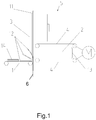
- FIG. 1 shows an embodiment of a cutting device according to the invention.
- the slicing device 5 has a knife 11 which cuts a food bar 2 into food slices 12.
- each food bar 2 with a conveyor 4, here two conveyor belts 4, continuously or intermittently transported in the direction of the cutting plane 6 of the blade 11.
- a storage table 1 which is provided with means of transport, on which they are each configured to a portion 14, here a stack.
- These portions 14 are then removed from the cutting blade area and then packed.
- the person skilled in the art recognizes that several food bars can be cut open at the same time.
- the slice thickness results from the feed distance of the food bar between two cuts. At a constant blade rotation speed, the regulation of the slice thickness is carried out via the feed speed of the food bar.
- the slicing device may have one gripper (not shown) for each feed line, which grips the rear end 13 of the food bar 2 before or during the slicing process and stabilizes it during the slicing process.
- a means 3, in this case at least one projection is provided on the cutting blade, which corotates with the cutting blade 11 at the same speed and generates a gas, in particular air flow, which stabilizes the at least partially, in particular completely cut, food disc in a desired shape and / or shapes.
- the gas, in particular air stream preferably flows along the side of the food disc facing the food bar, in particular between the food disc and the cutting blade.
- the gas, in particular air flow can be pulsed and / or continuous.
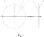
- FIG. 2 shows a first embodiment of the cutting blade 11 according to the invention here a circular blade.
- This has a cutting edge 7, with the food disc 12 is separated from the food bar 2.
- the circular blade rotates during cutting both about its central axis 15 and about an orbital axis (not shown), wherein the speed of the cutting blade 11 about its central axis 15 is preferably a multiple of its speed around the orbital axis.
- the cutting blade has a means 3, with which during its rotation, in particular about its central axis 15, a gas, in particular air flow, is generated. This preferably pulse-like and / or continuous air flow forms and / or stabilizes each at least partially cut food disc, especially during its flight to the tray table.
- the cut food disc can be kept, for example in a substantially planar shape, which is for example for a stacked or shingled portion of advantage.
- the gas in particular air flow
- the means is a projection which is arranged on the side facing away from the food latch side of the cutting blade.
- the means 3 may be a sheet metal part which is fastened to the cutting blade 11, for example, by welding, gluing and / or by means of screws, rivets or the like.
- the means 3 is provided integrally with the cutting blade and can be made, for example, by forming, for example, a bulge or a material accumulation, from the material of the cutting blade.
- the one-piece embodiment of the cutting blade according to the invention has been found to be particularly hygienic.
Description
Die vorliegende Erfindung betrifft ein rotierendes Schneidmesser, das von einem Lebensmittelriegel eine Vielzahl von Lebensmittelscheiben abschneidet, wobei das Schneidmesser an einer Messeraufnahme vorgesehen ist. Des Weiteren betrifft die vorliegende Erfindung eine Aufschneidevorrichtung aufweisend das erfindungsgemäße Schneidmesser und ein Verfahren zum Aufschneiden eines Lebensmittelriegels, bei dem ein rotierendes Schneidmesser eine Vielzahl von Lebensmittelscheiben von einem Lebensmittelriegel abtrennt sowie ein Verfahren zum Aufschneiden eines Lebensmittelriegels, bei dem ein rotierendes Schneidmesser, das an einer Messeraufnahme angeordnet ist, eine Vielzahl von Lebensmittelscheiben von einem Lebensmittelriegel abtrennt und zwischen zwei Lebensmittelscheiben ein Interleaver angeordnet wird.The present invention relates to a rotary cutting knife which cuts a plurality of food slices from a food bar, the cutting knife being provided on a knife holder. Furthermore, the present invention relates to a slicing device comprising the cutting knife according to the invention and a method for slicing a food bar, in which a rotating cutting knife a plurality of food slices separated from a food bar and a method for slicing a food bar, in which a rotating cutting blade, on a Knife receptacle is arranged, a plurality of food slices separated from a food bar and between two food slices an interleaver is arranged.
Derartige Schneidmesser, Vorrichtungen sowie Verfahren sind aus dem Stand der Technik, beispielsweise der
Es war deshalb die Aufgabe der vorliegenden Erfindung ein Schneidmesser zur Verfügung zu stellen, mit dem eine Lebensmittelscheibe während des Abschneidens und/oder während ihres Fluges in einer gewünschten Form stabilisiert und/oder geformt wird.It was therefore an object of the present invention to provide a cutting blade with which a food slice is stabilized and / or shaped during cutting and / or during its flight in a desired shape.
Gelöst wird die Aufgabe mit einem rotierenden Schneidmesser gemäß Patentanspruch 1.The problem is solved with a rotating cutting blade according to claim 1.
Die zu diesem Gegenstand der vorliegenden Erfindung gemachten Ausführungen gelten für die anderen Gegenstände der vorliegenden Erfindung gleichermaßen und umgekehrt.The statements made on this subject of the present invention apply equally to the other objects of the present invention and vice versa.
Die vorliegende Erfindung betrifft ein rotierendes Schneidmesser, das von einem Lebensmittel eine Vielzahl von Lebensmittelscheiben abschneidet. Bei einem derartigen Schneidmesser kann es sich beispielsweise um einen Kreismesser, ein Sichelmesser oder um ein Spiralmesser handeln. Vorzugsweise ist das Messer ein Kreismesser, das sich auf einer Orbitalbahn bewegt und sich beim Abschneiden einer Lebensmittelscheibe mehrfach um seine eigene Mittenachse dreht. Das Messer ist in der Regel an einer Messeraufnahme, die Teil eines Rotors einer Aufschneidevorrichtung ist, angeordnet. Bei solchen Aufschneidevorrichtungen wird ein Lebensmittelriegel entlang einer Vorschubtrasse kontinuierlich oder intermittierend in Richtung des Schneidmessers transportiert. Dieses Schneidmesser trennt von dem vorderen Ende des Lebensmittelriegels Lebensmittelscheiben ab. Die Dicke einer Lebensmittelscheibe wird durch den Vorschub, um den der Lebensmittelriegel weiter transportiert wird, während sich das Schneidmesser nicht im schneidenden Eingriff mit dem Lebensmittelriegel befindet, bestimmt. Nach dem Abschneiden fallen die Lebensmittelscheiben, insbesondere entlang einer Flugkurve, auf einen Ablagetisch und/oder auf eine bereits abgeschnittene Lebensmittelscheibe, wo sie zu einer Portion konfiguriert und dann abtransportiert werden.The present invention relates to a rotary cutting blade which cuts a plurality of food slices from a food. In such a Cutting knives may be, for example, a circular knife, a sickle knife or a spiral knife. Preferably, the knife is a circular knife that moves on an orbital path and rotates several times around its own center axis when cutting a food slice. The knife is usually arranged on a blade receptacle, which is part of a rotor of a slicing device. In such slicing devices, a food bar is transported along a feed path continuously or intermittently in the direction of the cutting blade. This cutting knife separates food slices from the front end of the food rack. The thickness of a food slice is determined by the feed rate by which the food bar is further transported while the cutting knife is not in cutting engagement with the food bar. After cutting, the food slices fall, in particular along a flight curve, on a storage table and / or on an already cut food disc, where they are configured to a serving and then transported away.
Erfindungsgemäß ist nun das Schneidmesser so gestaltet, dass eine Gas-, insbesondere Luftströmung erzeugt wird, die jede Lebensmittelscheibe während des Schneidens und/oder danach, d.h. während sie auf den Ablagetisch und/oder auf dort bereits vorhandene Lebensmittelscheiben fällt, formt und/oder in einer gewünschten Form zumindest teilweise und/oder zeitweise stabilisiert. Der Gas-, insbesondere Luftstrom strömt dabei entlang dem bereits abgeschnittenen Teil der Lebensmittelscheibe und/oder entlang der vollständig abgeschnitten, sich vorzugsweise im Flug befindlichen Lebensmittelscheibe und formt und/oder stabilisiert diese. Durch das Mittel kann ein pulsierender oder ein kontinuierlicher Gas-, insbesondere Luftstrom, erzeugt werden. Der Luftstrom kann einen Impuls auf die Lebensmittelschreibe ausüben und/oder einen Unterdruck auf einer Seite der Lebensmittelscheibe erzeugen, wodurch die Lebensmittelscheibe geformt und/oder in ihrer gewünschten Form stabilisiert wird. Der Luftstrom kann auch dazu eingesetzt werden das Schneidmesser bei seiner Rotation zu stabilisieren, so dass es beispielsweise weniger schwingt.According to the invention, the cutting blade is now designed so that a gas, in particular air flow is generated, which each food disc during cutting and / or thereafter, i. while it falls on the tray and / or there already existing food slices formed and / or at least partially and / or temporarily stabilized in a desired form. The gas, in particular air flow, flows along the already cut-off part of the food disc and / or along the food slice, which is completely cut off, preferably in flight, and shapes and / or stabilizes it. By means of a pulsating or a continuous gas, in particular air flow can be generated. The airflow may impart a pulse to the foodstuff writing and / or create a vacuum on one side of the food slice, thereby shaping the food slice and / or stabilizing it in its desired shape. The air flow can also be used to stabilize the cutting blade during its rotation, so that it oscillates less, for example.
Alternativ oder zusätzlich wird der von dem Mittel erzeugte Gas-, insbesondere Luftstrom, dazu eingesetzt ein Interleaver an jeweils eine abgeschnittene Lebensmittelscheibe anzulegen. Ein Interleaver ist ein Stück aus Papier oder einer papierähnlichen Substanz, das zwischen zwei Lebensmittelscheiben angeordnet wird, um deren Haftung zu vermindern.Alternatively or additionally, the gas, in particular air stream, generated by the agent is used to apply an interleaver to a respective cut-off food disc. An interleaver is a piece of paper or a paper-like substance placed between two food slices to reduce their adhesion.
Das Mittel zur Erzeugung des Gas-, insbesondere Luftstroms kann aus einem beliebigen Werkstoff hergestellt werden, wobei es vorzugsweise aus Metall, insbesondere aus Stahl gefertigt ist.The means for generating the gas, in particular air stream can be made of any material, wherein it is preferably made of metal, in particular made of steel.
Erfindungsgemäß ist das Mittel ein Vorsprung, der auf der dem Lebensmittelriegel abgewandten Seite des Schneidmessers vorgesehen ist. Beispielsweise kann es sich bei dem Mittel um ein Blechteil handeln, das an dem Schreibmesser, beispielweise stoffschlüssig, insbesondere durch Schweißen oder Kleben und/oder kraft- und/oder formschlüssig, beispielsweise mittels Schrauben, Nieten oder dergleichen, befestigt wird. Besonders bevorzugt sind das Schneidmesser und das Mittel einstückig vorgesehen. Vorzugsweise wird das Mittel durch eine lokale Materialanhäufung oder durch Umformen des Materials, aus dem das Schneidmesser gefertigt ist, erzeugt. Insbesondere handelt es sich bei dem Mittel um eine Ausbuchtung, die in der Oberfläche des Schneidmessers vorgesehen wird.According to the invention, the means is a projection which is provided on the side facing away from the food bar side of the cutting blade. For example, the means may be a sheet metal part which is fastened to the writing knife, for example by material bonding, in particular by welding or gluing and / or positive and / or positive locking, for example by means of screws, rivets or the like. Particularly preferably, the cutting blade and the means are provided in one piece. Preferably, the agent is produced by local accumulation of material or by reshaping the material from which the cutting blade is made. In particular, the means is a bulge provided in the surface of the cutting blade.
Ein weiterer Gegenstand der vorliegenden Erfindung ist eine Aufschneidevorrichtung, an der das erfindungsgemäße Schneidmesser angeordnet ist.Another object of the present invention is a slicing device on which the cutting blade according to the invention is arranged.
Die zu diesem Gegenstand der vorliegenden Erfindung gemachten Ausführungen gelten für die anderen Gegenstände der vorliegenden Erfindung gleichermaßen und umgekehrt.The statements made on this subject of the present invention apply equally to the other objects of the present invention and vice versa.
Noch ein Gegenstand der vorliegenden Erfindung ist ein Verfahren zum Aufschneiden eines oder mehrerer Lebensmittelriegel, bei dem ein rotierendes Schneidmesser, das an einer Messeraufnahme angeordnet ist, eine Vielzahl von Lebensmittelscheiben von einem oder mehrerer Lebensmittelriegel abtrennt, wobei zwischen zwei Lebensmittelscheiben ein Interleaver angeordnet wird, bei dem der Interleaver durch einen von einem an dem Schneidmesser und/oder der Messeraufnahme angeordneten Mittel erzeugten Luftstrom an eine Lebensmittelscheibe angelegt wird.Yet another object of the present invention is a method for slicing one or more food bars, in which a rotating cutting knife, which is arranged on a knife holder, a plurality of food slices separated from one or more food bars, wherein between two food slices an interleaver is arranged the interleaver is applied to a food disc by a stream of air generated by means disposed on the cutting blade and / or the knife receiving means.
Die zu diesem Gegenstand der vorliegenden Erfindung gemachten Ausführungen gelten für die anderen Gegenstände der vorliegenden Erfindung gleichermaßen und umgekehrt.The statements made on this subject of the present invention apply equally to the other objects of the present invention and vice versa.
Vorzugsweise wird mittels des/der Gas- insbesondere Luftstrom/ströme, mindestens ein zusätzlicher Stoff auf die Messer- und/oder Produktoberfläche, beispielsweise ein Desinfektions-/Reinigungsmittel oder ein Austauschgas aufgebracht.Preferably, by means of the gas / air streams / streams, at least one additional substance is applied to the knife and / or product surface, for example a disinfectant / cleaning agent or a replacement gas.
Im Folgenden wird die Erfindung anhand der
- Figur 1
- zeigt die erfindungsgemäße Aufschneidevorrichtung.
-
Figuren 2 - zeigt eine Ausführungsform des erfindungsgemäßen Schneidmessers.
- FIG. 1
- shows the slicing device according to the invention.
- Figures 2
- shows an embodiment of the cutting blade according to the invention.
Erfindungsgemäß ist an dem Schneidmesser ein Mittel 3, hier mindestens ein Vorsprung, vorgesehen, das mit dem Schneidmesser 11 mit derselben Drehzahl korotiert und dabei einen Gas-, insbesondere Luftstrom, erzeugt, der die zumindest teilweise, insbesondere vollständig abgeschnittene Lebensmittelscheibe in einer gewünschten Form stabilisiert und/oder formt. Der Gas-, insbesondere Luftstrom, strömt dazu vorzugsweise entlang der dem Lebensmittelriegel zugewandten Seite der Lebensmittelscheibe entlang, insbesondere zwischen der Lebensmittelscheibe und dem Schneidmesser. Der Gas-, insbesondere Luftstrom kann impulsartig und/oder kontinuierlich sein.
According to the invention, a
- 11
- Ablagetischtray table
- 22
- LebensmittelriegelFood bar
- 33
- Mittel zur Erzeugung einer Gas- insbesondere LuftströmungMeans for generating a gas, in particular air flow
- 44
- TransportmittelMode of Transport
- 55
- Aufschneidevorrichtungslicing
- 66
- Schneidebenecutting plane
- 77
-
Schneidkante des Schneidmessers 11Cutting edge of the
cutting blade 11 - 88th
- Rotor, MesseraufnahmeRotor, knife holder
- 99
- Abdeckungcover
- 1010
- Gas-, insbesondere LuftstromGas, in particular air flow
- 1111
- Messer, KreismesserKnives, circular knives
- 1212
- LebensmittelscheibenFood slices
- 1313
- rückwärtiges Enderear end
- 1414
- Portionportion
- 1515
- Mittelachse des SchneidmessersCenter axis of the cutting blade
Claims (11)
- Rotating cutting blade (11) which cuts a plurality of food slices (12) from one or several food slabs (2), wherein the cutting blade is provided on a blade receiving means (8), wherein at least one means (3) is provided on the cutting blade and/or in that a cutting blade is developed in a corresponding manner such that one or several gas flows, in particular air flows, are produced which form each food slice during the cutting process and/or thereafter and/or stabilize it in a desired form at least in part and/or at times and/or apply an interleaver to a food slice, characterized in that the means (3) is at least one projection which is arranged on the side of the cutting blade which is remote from the food slab.
- Rotating blade (11) according to Claim 1, characterized in that the cutting blade and the means (3) are provided in one piece.
- Rotating blade (11) according to one of the preceding claims, characterized in that the means is at least one vane (13) which produces the air flow.
- Rotating blade (11) according to one of the preceding claims, characterized in that the alignment of the vane (13) is modifiable relative to the cutting blade.
- Rotating blade (11) according to one of the preceding claims, characterized in that the means rotates at the same speed as the cutting blade.
- Rotating blade (11) according to one of the preceding claims, characterized in that the means rotates at a different speed to the cutting blade.
- Rotating blade (11) according to one of the preceding claims, characterized in that the means rotates in the opposite direction to the cutting blade.
- Rotating blade (11) according to one of the preceding claims, characterized in that the means rotates in the same direction of rotation as the cutting blade.
- Rotating blade (11) according to one of the preceding claims, characterized in that the cutting blade is a circular blade which circulates along an orbital path.
- Slicing device comprising a cutting blade according to one of the preceding claims.
- Method for slicing one or several slabs of food where a rotating cutting blade (11), which is arranged on a blade receiving means (8), separates a plurality of food slices (12) from one or several food slabs (11), wherein an interleaver is arranged between two food slices, characterized in that the interleaver is applied to a food slice as a result of an air flow which is produced by a means which is arranged on the cutting blade and/or the blade receiving means.
Applications Claiming Priority (2)
| Application Number | Priority Date | Filing Date | Title |
|---|---|---|---|
| DE201210004960 DE102012004960A1 (en) | 2012-03-14 | 2012-03-14 | Cutting knife with a means for generating an air flow |
| PCT/EP2013/055289 WO2013135843A2 (en) | 2012-03-14 | 2013-03-14 | Cutting blade having a means for producing an air flow |
Publications (3)
| Publication Number | Publication Date |
|---|---|
| EP2825354A2 EP2825354A2 (en) | 2015-01-21 |
| EP2825354B1 true EP2825354B1 (en) | 2017-09-06 |
| EP2825354B2 EP2825354B2 (en) | 2020-12-02 |
Family
ID=47891709
Family Applications (1)
| Application Number | Title | Priority Date | Filing Date |
|---|---|---|---|
| EP13709899.2A Active EP2825354B2 (en) | 2012-03-14 | 2013-03-14 | Cutting blade with means for producing an airstream |
Country Status (5)
| Country | Link |
|---|---|
| US (1) | US20150047482A1 (en) |
| EP (1) | EP2825354B2 (en) |
| DE (1) | DE102012004960A1 (en) |
| ES (1) | ES2650389T5 (en) |
| WO (1) | WO2013135843A2 (en) |
Families Citing this family (7)
| Publication number | Priority date | Publication date | Assignee | Title |
|---|---|---|---|---|
| DE102012112103A1 (en) * | 2012-12-11 | 2014-06-12 | Gea Food Solutions Germany Gmbh | Slicing device with a folding strip |
| DE102013007275A1 (en) * | 2013-04-26 | 2014-11-13 | Weber Maschinenbau Gmbh Breidenbach | Food slicing knife with a radio transponder |
| DE102014118164A1 (en) * | 2014-12-08 | 2016-06-09 | Weber Maschinenbau Gmbh Breidenbach | cutting blade |
| EP3380419B1 (en) * | 2015-11-23 | 2020-01-01 | GEA Food Solutions Germany GmbH | Method and device for portioning slices of food with change of shape, in particular folding, of the portion |
| US11073447B2 (en) * | 2016-03-31 | 2021-07-27 | Agilent Technologies, Inc. | Apparatus and methods for transferring a tissue section |
| ES2818728T3 (en) * | 2017-12-05 | 2021-04-13 | Marel Meat Bv | A food separator apparatus |
| DE102020112863A1 (en) * | 2020-05-12 | 2021-11-18 | Tvi Entwicklung Und Produktion Gmbh | Weight variation method and slicing machine for his operation |
Citations (24)
| Publication number | Priority date | Publication date | Assignee | Title |
|---|---|---|---|---|
| US1878071A (en) | 1926-09-08 | 1932-09-20 | Mij Exploitatie Octrooien Nv | Slice deflector |
| US1957623A (en) | 1931-11-21 | 1934-05-08 | Ind Patents Corp | Slicing machine |
| US3727504A (en) | 1971-08-05 | 1973-04-17 | A Osterholt | Meat slicing knife |
| DE2842105A1 (en) | 1978-09-27 | 1980-04-10 | Kober Kg A | ROTARY CUTTING KNIFE WITH WAVE-SHAPED CUTTING EDGES THAT MAKE A PULLING CUT |
| DE3742864A1 (en) | 1987-12-17 | 1989-07-27 | Kurt Horn | Knife with constant cutting sharpness |
| DE3818474A1 (en) | 1988-05-31 | 1989-12-21 | Holac Maschbau Gmbh | Method and device for cutting foodstuffs |
| DE4031671A1 (en) | 1990-10-05 | 1992-04-09 | Natec Reich Summer Gmbh Co Kg | Circular cutter for slicing sausage and cheese - is power driven on eccentric axis and has contra-rotating eccentric disc with separate power unit |
| US5136908A (en) | 1991-07-29 | 1992-08-11 | Valley Slicer Co. | Food slicer apparatus and knife therefor |
| JPH06320493A (en) | 1993-05-14 | 1994-11-22 | Nanjo Tekko Kk | Vertical type meat slicer |
| DE19739788A1 (en) | 1997-09-10 | 1999-03-11 | Alpma Alpenland Masch | Cutter knife for food slicer |
| DE20009726U1 (en) | 2000-05-30 | 2000-08-24 | System Gmbh | Rotary cutter with air-cooled cutter heads |
| DE19926461A1 (en) | 1999-06-10 | 2000-12-14 | Biforce Anstalt Vaduz | Device for slicing food products |
| DE10057333A1 (en) | 2000-11-17 | 2002-05-23 | Cfs Gmbh Kempten | Device on cutting machines |
| DE10332483A1 (en) | 2002-07-12 | 2004-01-29 | Kuchler, Fritz, Dipl.-Kaufm. | Slicing machine for cold meats has blower above positioning tray for interleaf cut foil blanks for precise foil positioning and exact package welding |
| DE102004007671A1 (en) | 2004-02-13 | 2005-09-22 | Cfs Kempten Gmbh | Food portions generating method e.g. for portions cut in slices, bars, involves having several food cut into slices and separated by distance with slices can be folded and or formed as waves |
| DE102005003040A1 (en) | 2004-08-19 | 2006-03-09 | Astor Schneidwerkzeuge Gmbh | Knife for food slicing machines |
| EP2082854A1 (en) | 2008-01-28 | 2009-07-29 | Arelmasani Holding B.V. | Separating device for food products |
| WO2010053595A1 (en) | 2008-11-05 | 2010-05-14 | Spraying Systems Co. | Pathogen reduction system for the preparation of sliced food products |
| WO2010086006A1 (en) | 2009-01-30 | 2010-08-05 | Weber Maschinenbau Gmbh Breidenbach | Rotating cutting blade for food |
| DE102009030550A1 (en) | 2009-06-25 | 2010-12-30 | Weber Maschinenbau Gmbh Breidenbach | cutting blade |
| DE102009032974A1 (en) | 2009-07-14 | 2011-01-20 | Weber Maschinenbau Gmbh Breidenbach | Device for slicing of food products, particularly high speed slicer, comprises carrier for slicing element, and slicing plane is provided, which comprises defined slicing edge |
| WO2011014914A1 (en) | 2009-08-03 | 2011-02-10 | Frelk Industries Pty Ltd | Cutting device |
| EP2407038A1 (en) | 2010-07-15 | 2012-01-18 | Albert Handtmann Maschinenfabrik GmbH & Co. KG | Method and device for cooling food machines |
| WO2013152842A1 (en) | 2012-04-11 | 2013-10-17 | Weber Maschinenbau Gmbh Breidenbach | Cutting blade |
Family Cites Families (27)
| Publication number | Priority date | Publication date | Assignee | Title |
|---|---|---|---|---|
| DE470132C (en) * | 1926-09-08 | 1929-01-05 | Berkel Patent Nv | Slice deflector for slicers |
| US1974602A (en) * | 1931-08-03 | 1934-09-25 | Ind Patents Corp | Slicing machine |
| US3282263A (en) * | 1963-07-29 | 1966-11-01 | Christensen Diamond Prod Co | Face discharge cutting blades |
| US3754359A (en) * | 1970-09-16 | 1973-08-28 | Spam D Avray | Abrasion tools |
| US3932967A (en) * | 1975-05-07 | 1976-01-20 | Hanes Donald M | Sharpener for rotary electric razor |
| DE2623339C2 (en) * | 1976-05-25 | 1982-02-25 | Ernst Prof. Dr.-Ing. 2106 Bendestorf Salje | Circular saw blade |
| US4282910A (en) * | 1980-07-10 | 1981-08-11 | Michigan Technological University | Fingerling shear |
| DE3239178A1 (en) * | 1982-10-22 | 1984-04-26 | Natec Reich, Summer GmbH & Co KG, 8999 Heimenkirch | MACHINE FOR CUTTING CUT BAR |
| US4712458A (en) * | 1986-12-11 | 1987-12-15 | Oscar Mayer Foods Corporation | Food loaf slicing machine with improved stacking characteristics |
| US4776251A (en) * | 1987-06-12 | 1988-10-11 | Pacific Saw And Knife Company | Circular saw blade with circumferentally extending laser-cut slots |
| DE3911803A1 (en) * | 1989-04-11 | 1990-10-31 | Walter Arndt | Circular blade cooler for paper cutting machines - has rotary blade retaining flange with rotor vanes |
| US5078035A (en) * | 1989-08-21 | 1992-01-07 | Diamond Products, Inc. | Circular saw blade |
| JP3327482B2 (en) * | 1993-02-25 | 2002-09-24 | ワタナベフーマック株式会社 | Section bending equipment for food slicers |
| DE4402923A1 (en) * | 1994-02-01 | 1995-08-03 | Dixie Union Verpackungen Gmbh | Device for inserting pieces of paper into cold cuts |
| DK0961668T3 (en) * | 1995-10-12 | 2002-04-15 | Gebelius Hjoerdis Florence Mar | Method of preventing or reducing magnetism formation in two adjacent saw blades rotating in opposite directions and device for using the method |
| US6173499B1 (en) * | 1998-12-08 | 2001-01-16 | Gary M. Hegoas | Vent cover for an electric saw |
| DE29901713U1 (en) * | 1999-02-01 | 2000-06-29 | Powertools International Gmbh | Saw blade |
| KR100319131B1 (en) * | 1999-06-14 | 2001-12-29 | 정운조 | A cutting cleaver for a meat |
| JP3874990B2 (en) * | 2000-04-18 | 2007-01-31 | 株式会社マキタ | Lighting equipment for cutting machine |
| USD463965S1 (en) * | 2001-02-15 | 2002-10-08 | Ehwa Diamond Ind. Co., Ltd. | Grinding wheel |
| KR100440869B1 (en) * | 2001-02-19 | 2004-07-19 | 이화다이아몬드공업 주식회사 | Saw blade shank |
| US20060090429A1 (en) * | 2004-11-01 | 2006-05-04 | Wall Jere J | Spinner top for an air filter |
| WO2007050677A2 (en) * | 2005-10-25 | 2007-05-03 | Formax, Inc. | Sheet interleaver for slicing apparatus |
| SE531916C2 (en) * | 2008-01-24 | 2009-09-08 | Haellde Maskiner Ab | Cutting disc |
| DE102009011398A1 (en) * | 2009-03-03 | 2010-09-09 | Weber Maschinenbau Gmbh Breidenbach | cutter |
| DE102009011399A1 (en) * | 2009-03-03 | 2010-09-09 | Weber Maschinenbau Gmbh Breidenbach | cutter |
| DE102012007290A1 (en) * | 2012-04-12 | 2013-10-17 | Weber Maschinenbau Gmbh Breidenbach | Cutting knife with deflector |
-
2012
- 2012-03-14 DE DE201210004960 patent/DE102012004960A1/en not_active Withdrawn
-
2013
- 2013-03-14 EP EP13709899.2A patent/EP2825354B2/en active Active
- 2013-03-14 ES ES13709899T patent/ES2650389T5/en active Active
- 2013-03-14 WO PCT/EP2013/055289 patent/WO2013135843A2/en active Application Filing
- 2013-03-14 US US14/384,230 patent/US20150047482A1/en not_active Abandoned
Patent Citations (24)
| Publication number | Priority date | Publication date | Assignee | Title |
|---|---|---|---|---|
| US1878071A (en) | 1926-09-08 | 1932-09-20 | Mij Exploitatie Octrooien Nv | Slice deflector |
| US1957623A (en) | 1931-11-21 | 1934-05-08 | Ind Patents Corp | Slicing machine |
| US3727504A (en) | 1971-08-05 | 1973-04-17 | A Osterholt | Meat slicing knife |
| DE2842105A1 (en) | 1978-09-27 | 1980-04-10 | Kober Kg A | ROTARY CUTTING KNIFE WITH WAVE-SHAPED CUTTING EDGES THAT MAKE A PULLING CUT |
| DE3742864A1 (en) | 1987-12-17 | 1989-07-27 | Kurt Horn | Knife with constant cutting sharpness |
| DE3818474A1 (en) | 1988-05-31 | 1989-12-21 | Holac Maschbau Gmbh | Method and device for cutting foodstuffs |
| DE4031671A1 (en) | 1990-10-05 | 1992-04-09 | Natec Reich Summer Gmbh Co Kg | Circular cutter for slicing sausage and cheese - is power driven on eccentric axis and has contra-rotating eccentric disc with separate power unit |
| US5136908A (en) | 1991-07-29 | 1992-08-11 | Valley Slicer Co. | Food slicer apparatus and knife therefor |
| JPH06320493A (en) | 1993-05-14 | 1994-11-22 | Nanjo Tekko Kk | Vertical type meat slicer |
| DE19739788A1 (en) | 1997-09-10 | 1999-03-11 | Alpma Alpenland Masch | Cutter knife for food slicer |
| DE19926461A1 (en) | 1999-06-10 | 2000-12-14 | Biforce Anstalt Vaduz | Device for slicing food products |
| DE20009726U1 (en) | 2000-05-30 | 2000-08-24 | System Gmbh | Rotary cutter with air-cooled cutter heads |
| DE10057333A1 (en) | 2000-11-17 | 2002-05-23 | Cfs Gmbh Kempten | Device on cutting machines |
| DE10332483A1 (en) | 2002-07-12 | 2004-01-29 | Kuchler, Fritz, Dipl.-Kaufm. | Slicing machine for cold meats has blower above positioning tray for interleaf cut foil blanks for precise foil positioning and exact package welding |
| DE102004007671A1 (en) | 2004-02-13 | 2005-09-22 | Cfs Kempten Gmbh | Food portions generating method e.g. for portions cut in slices, bars, involves having several food cut into slices and separated by distance with slices can be folded and or formed as waves |
| DE102005003040A1 (en) | 2004-08-19 | 2006-03-09 | Astor Schneidwerkzeuge Gmbh | Knife for food slicing machines |
| EP2082854A1 (en) | 2008-01-28 | 2009-07-29 | Arelmasani Holding B.V. | Separating device for food products |
| WO2010053595A1 (en) | 2008-11-05 | 2010-05-14 | Spraying Systems Co. | Pathogen reduction system for the preparation of sliced food products |
| WO2010086006A1 (en) | 2009-01-30 | 2010-08-05 | Weber Maschinenbau Gmbh Breidenbach | Rotating cutting blade for food |
| DE102009030550A1 (en) | 2009-06-25 | 2010-12-30 | Weber Maschinenbau Gmbh Breidenbach | cutting blade |
| DE102009032974A1 (en) | 2009-07-14 | 2011-01-20 | Weber Maschinenbau Gmbh Breidenbach | Device for slicing of food products, particularly high speed slicer, comprises carrier for slicing element, and slicing plane is provided, which comprises defined slicing edge |
| WO2011014914A1 (en) | 2009-08-03 | 2011-02-10 | Frelk Industries Pty Ltd | Cutting device |
| EP2407038A1 (en) | 2010-07-15 | 2012-01-18 | Albert Handtmann Maschinenfabrik GmbH & Co. KG | Method and device for cooling food machines |
| WO2013152842A1 (en) | 2012-04-11 | 2013-10-17 | Weber Maschinenbau Gmbh Breidenbach | Cutting blade |
Also Published As
| Publication number | Publication date |
|---|---|
| ES2650389T3 (en) | 2018-01-18 |
| EP2825354A2 (en) | 2015-01-21 |
| US20150047482A1 (en) | 2015-02-19 |
| WO2013135843A2 (en) | 2013-09-19 |
| ES2650389T5 (en) | 2021-09-14 |
| EP2825354B2 (en) | 2020-12-02 |
| WO2013135843A3 (en) | 2014-01-16 |
| DE102012004960A1 (en) | 2013-09-19 |
Similar Documents
| Publication | Publication Date | Title |
|---|---|---|
| EP2825354B1 (en) | Cutting blade with means for producing an airstream | |
| WO2015154871A1 (en) | Slicing device comprising rapid-manufacturing components | |
| EP3204201A1 (en) | Sliced food portions | |
| EP2900440B1 (en) | Device and method for continuously producing portions | |
| EP3105020B1 (en) | Cutting device with a feed channel for interleaving paper | |
| DE102008061330A1 (en) | Slicing pieces of cheese | |
| EP2884845B1 (en) | System for producing end products by cutting flat and hollow wafer blocks | |
| DE102012109003A1 (en) | Slicer | |
| SE442719B (en) | COOKING TOOL FOR CUTTING SHEETS OF FOOD | |
| EP3139752B1 (en) | Gripper comprising an ultrasonic sensor | |
| EP3380419B1 (en) | Method and device for portioning slices of food with change of shape, in particular folding, of the portion | |
| EP2894016A1 (en) | Method and device for cutting food products | |
| WO2014090637A1 (en) | Slicing device with a folding strip | |
| EP3500410B1 (en) | Method for slicing foodstuff into portions of precise weight | |
| DE102013218263A1 (en) | Apparatus for slicing food products such as sausage, has wear portion which is provided to feed, support and/or fix interleaver web material during and/or prior to cutting of interleaver pieces, and is integrated in cutting block | |
| EP2065145B1 (en) | Use of a device for grating cheese | |
| EP3062976B1 (en) | Slicer with blade made of plastics | |
| EP3478464A1 (en) | Divided folding means | |
| EP2090409A1 (en) | Method for dividing up blocks of food products | |
| EP2487013B1 (en) | Food processing device | |
| DE102015120481A1 (en) | Apparatus for processing a food product having a surface layer | |
| EP3386693B1 (en) | Method for carrying out a trimming cut | |
| EP1477074A1 (en) | Method for separating tobacco from a block of tobacco and device for performing the method | |
| DE112014004235T5 (en) | Rotating cutting blade assembly | |
| DE102012112927A1 (en) | Method for depositing cut slices of food of product e.g. sausage to portion to portioning belt, involves providing portioning belt as cross shingle belt during slicing and/or depositing of portion for performing oscillatory movement |
Legal Events
| Date | Code | Title | Description |
|---|---|---|---|
| PUAI | Public reference made under article 153(3) epc to a published international application that has entered the european phase |
Free format text: ORIGINAL CODE: 0009012 |
|
| 17P | Request for examination filed |
Effective date: 20140909 |
|
| AK | Designated contracting states |
Kind code of ref document: A2 Designated state(s): AL AT BE BG CH CY CZ DE DK EE ES FI FR GB GR HR HU IE IS IT LI LT LU LV MC MK MT NL NO PL PT RO RS SE SI SK SM TR |
|
| AX | Request for extension of the european patent |
Extension state: BA ME |
|
| DAX | Request for extension of the european patent (deleted) | ||
| 17Q | First examination report despatched |
Effective date: 20151127 |
|
| GRAP | Despatch of communication of intention to grant a patent |
Free format text: ORIGINAL CODE: EPIDOSNIGR1 |
|
| INTG | Intention to grant announced |
Effective date: 20170412 |
|
| GRAS | Grant fee paid |
Free format text: ORIGINAL CODE: EPIDOSNIGR3 |
|
| GRAA | (expected) grant |
Free format text: ORIGINAL CODE: 0009210 |
|
| AK | Designated contracting states |
Kind code of ref document: B1 Designated state(s): AL AT BE BG CH CY CZ DE DK EE ES FI FR GB GR HR HU IE IS IT LI LT LU LV MC MK MT NL NO PL PT RO RS SE SI SK SM TR |
|
| REG | Reference to a national code |
Ref country code: GB Ref legal event code: FG4D Free format text: NOT ENGLISH |
|
| REG | Reference to a national code |
Ref country code: CH Ref legal event code: EP Ref country code: AT Ref legal event code: REF Ref document number: 925369 Country of ref document: AT Kind code of ref document: T Effective date: 20170915 |
|
| REG | Reference to a national code |
Ref country code: IE Ref legal event code: FG4D Free format text: LANGUAGE OF EP DOCUMENT: GERMAN |
|
| REG | Reference to a national code |
Ref country code: DE Ref legal event code: R096 Ref document number: 502013008277 Country of ref document: DE |
|
| REG | Reference to a national code |
Ref country code: NL Ref legal event code: FP |
|
| REG | Reference to a national code |
Ref country code: ES Ref legal event code: FG2A Ref document number: 2650389 Country of ref document: ES Kind code of ref document: T3 Effective date: 20180118 |
|
| REG | Reference to a national code |
Ref country code: LT Ref legal event code: MG4D |
|
| PG25 | Lapsed in a contracting state [announced via postgrant information from national office to epo] |
Ref country code: SE Free format text: LAPSE BECAUSE OF FAILURE TO SUBMIT A TRANSLATION OF THE DESCRIPTION OR TO PAY THE FEE WITHIN THE PRESCRIBED TIME-LIMIT Effective date: 20170906 Ref country code: LT Free format text: LAPSE BECAUSE OF FAILURE TO SUBMIT A TRANSLATION OF THE DESCRIPTION OR TO PAY THE FEE WITHIN THE PRESCRIBED TIME-LIMIT Effective date: 20170906 Ref country code: NO Free format text: LAPSE BECAUSE OF FAILURE TO SUBMIT A TRANSLATION OF THE DESCRIPTION OR TO PAY THE FEE WITHIN THE PRESCRIBED TIME-LIMIT Effective date: 20171206 Ref country code: FI Free format text: LAPSE BECAUSE OF FAILURE TO SUBMIT A TRANSLATION OF THE DESCRIPTION OR TO PAY THE FEE WITHIN THE PRESCRIBED TIME-LIMIT Effective date: 20170906 Ref country code: HR Free format text: LAPSE BECAUSE OF FAILURE TO SUBMIT A TRANSLATION OF THE DESCRIPTION OR TO PAY THE FEE WITHIN THE PRESCRIBED TIME-LIMIT Effective date: 20170906 |
|
| PG25 | Lapsed in a contracting state [announced via postgrant information from national office to epo] |
Ref country code: RS Free format text: LAPSE BECAUSE OF FAILURE TO SUBMIT A TRANSLATION OF THE DESCRIPTION OR TO PAY THE FEE WITHIN THE PRESCRIBED TIME-LIMIT Effective date: 20170906 Ref country code: LV Free format text: LAPSE BECAUSE OF FAILURE TO SUBMIT A TRANSLATION OF THE DESCRIPTION OR TO PAY THE FEE WITHIN THE PRESCRIBED TIME-LIMIT Effective date: 20170906 Ref country code: GR Free format text: LAPSE BECAUSE OF FAILURE TO SUBMIT A TRANSLATION OF THE DESCRIPTION OR TO PAY THE FEE WITHIN THE PRESCRIBED TIME-LIMIT Effective date: 20171207 Ref country code: BG Free format text: LAPSE BECAUSE OF FAILURE TO SUBMIT A TRANSLATION OF THE DESCRIPTION OR TO PAY THE FEE WITHIN THE PRESCRIBED TIME-LIMIT Effective date: 20171206 |
|
| REG | Reference to a national code |
Ref country code: FR Ref legal event code: PLFP Year of fee payment: 6 |
|
| PG25 | Lapsed in a contracting state [announced via postgrant information from national office to epo] |
Ref country code: PL Free format text: LAPSE BECAUSE OF FAILURE TO SUBMIT A TRANSLATION OF THE DESCRIPTION OR TO PAY THE FEE WITHIN THE PRESCRIBED TIME-LIMIT Effective date: 20170906 Ref country code: CZ Free format text: LAPSE BECAUSE OF FAILURE TO SUBMIT A TRANSLATION OF THE DESCRIPTION OR TO PAY THE FEE WITHIN THE PRESCRIBED TIME-LIMIT Effective date: 20170906 Ref country code: RO Free format text: LAPSE BECAUSE OF FAILURE TO SUBMIT A TRANSLATION OF THE DESCRIPTION OR TO PAY THE FEE WITHIN THE PRESCRIBED TIME-LIMIT Effective date: 20170906 |
|
| REG | Reference to a national code |
Ref country code: DE Ref legal event code: R026 Ref document number: 502013008277 Country of ref document: DE |
|
| PG25 | Lapsed in a contracting state [announced via postgrant information from national office to epo] |
Ref country code: EE Free format text: LAPSE BECAUSE OF FAILURE TO SUBMIT A TRANSLATION OF THE DESCRIPTION OR TO PAY THE FEE WITHIN THE PRESCRIBED TIME-LIMIT Effective date: 20170906 Ref country code: IS Free format text: LAPSE BECAUSE OF FAILURE TO SUBMIT A TRANSLATION OF THE DESCRIPTION OR TO PAY THE FEE WITHIN THE PRESCRIBED TIME-LIMIT Effective date: 20180106 Ref country code: SK Free format text: LAPSE BECAUSE OF FAILURE TO SUBMIT A TRANSLATION OF THE DESCRIPTION OR TO PAY THE FEE WITHIN THE PRESCRIBED TIME-LIMIT Effective date: 20170906 Ref country code: SM Free format text: LAPSE BECAUSE OF FAILURE TO SUBMIT A TRANSLATION OF THE DESCRIPTION OR TO PAY THE FEE WITHIN THE PRESCRIBED TIME-LIMIT Effective date: 20170906 |
|
| PLBI | Opposition filed |
Free format text: ORIGINAL CODE: 0009260 |
|
| PLAX | Notice of opposition and request to file observation + time limit sent |
Free format text: ORIGINAL CODE: EPIDOSNOBS2 |
|
| 26 | Opposition filed |
Opponent name: WEBER MASCHINENBAU GMBH BREIDENBACH Effective date: 20180530 |
|
| PG25 | Lapsed in a contracting state [announced via postgrant information from national office to epo] |
Ref country code: DK Free format text: LAPSE BECAUSE OF FAILURE TO SUBMIT A TRANSLATION OF THE DESCRIPTION OR TO PAY THE FEE WITHIN THE PRESCRIBED TIME-LIMIT Effective date: 20170906 |
|
| PG25 | Lapsed in a contracting state [announced via postgrant information from national office to epo] |
Ref country code: SI Free format text: LAPSE BECAUSE OF FAILURE TO SUBMIT A TRANSLATION OF THE DESCRIPTION OR TO PAY THE FEE WITHIN THE PRESCRIBED TIME-LIMIT Effective date: 20170906 |
|
| PG25 | Lapsed in a contracting state [announced via postgrant information from national office to epo] |
Ref country code: MT Free format text: LAPSE BECAUSE OF FAILURE TO SUBMIT A TRANSLATION OF THE DESCRIPTION OR TO PAY THE FEE WITHIN THE PRESCRIBED TIME-LIMIT Effective date: 20170906 |
|
| PLBB | Reply of patent proprietor to notice(s) of opposition received |
Free format text: ORIGINAL CODE: EPIDOSNOBS3 |
|
| REG | Reference to a national code |
Ref country code: CH Ref legal event code: PL |
|
| PG25 | Lapsed in a contracting state [announced via postgrant information from national office to epo] |
Ref country code: MC Free format text: LAPSE BECAUSE OF FAILURE TO SUBMIT A TRANSLATION OF THE DESCRIPTION OR TO PAY THE FEE WITHIN THE PRESCRIBED TIME-LIMIT Effective date: 20170906 |
|
| REG | Reference to a national code |
Ref country code: BE Ref legal event code: MM Effective date: 20180331 |
|
| REG | Reference to a national code |
Ref country code: IE Ref legal event code: MM4A |
|
| PG25 | Lapsed in a contracting state [announced via postgrant information from national office to epo] |
Ref country code: LU Free format text: LAPSE BECAUSE OF NON-PAYMENT OF DUE FEES Effective date: 20180314 |
|
| PG25 | Lapsed in a contracting state [announced via postgrant information from national office to epo] |
Ref country code: IE Free format text: LAPSE BECAUSE OF NON-PAYMENT OF DUE FEES Effective date: 20180314 |
|
| PG25 | Lapsed in a contracting state [announced via postgrant information from national office to epo] |
Ref country code: CH Free format text: LAPSE BECAUSE OF NON-PAYMENT OF DUE FEES Effective date: 20180331 Ref country code: LI Free format text: LAPSE BECAUSE OF NON-PAYMENT OF DUE FEES Effective date: 20180331 Ref country code: BE Free format text: LAPSE BECAUSE OF NON-PAYMENT OF DUE FEES Effective date: 20180331 |
|
| REG | Reference to a national code |
Ref country code: AT Ref legal event code: MM01 Ref document number: 925369 Country of ref document: AT Kind code of ref document: T Effective date: 20180314 |
|
| PG25 | Lapsed in a contracting state [announced via postgrant information from national office to epo] |
Ref country code: AT Free format text: LAPSE BECAUSE OF NON-PAYMENT OF DUE FEES Effective date: 20180314 |
|
| PG25 | Lapsed in a contracting state [announced via postgrant information from national office to epo] |
Ref country code: TR Free format text: LAPSE BECAUSE OF FAILURE TO SUBMIT A TRANSLATION OF THE DESCRIPTION OR TO PAY THE FEE WITHIN THE PRESCRIBED TIME-LIMIT Effective date: 20170906 |
|
| PG25 | Lapsed in a contracting state [announced via postgrant information from national office to epo] |
Ref country code: PT Free format text: LAPSE BECAUSE OF FAILURE TO SUBMIT A TRANSLATION OF THE DESCRIPTION OR TO PAY THE FEE WITHIN THE PRESCRIBED TIME-LIMIT Effective date: 20170906 Ref country code: HU Free format text: LAPSE BECAUSE OF FAILURE TO SUBMIT A TRANSLATION OF THE DESCRIPTION OR TO PAY THE FEE WITHIN THE PRESCRIBED TIME-LIMIT; INVALID AB INITIO Effective date: 20130314 |
|
| PG25 | Lapsed in a contracting state [announced via postgrant information from national office to epo] |
Ref country code: CY Free format text: LAPSE BECAUSE OF FAILURE TO SUBMIT A TRANSLATION OF THE DESCRIPTION OR TO PAY THE FEE WITHIN THE PRESCRIBED TIME-LIMIT Effective date: 20170906 Ref country code: MK Free format text: LAPSE BECAUSE OF NON-PAYMENT OF DUE FEES Effective date: 20170906 |
|
| PG25 | Lapsed in a contracting state [announced via postgrant information from national office to epo] |
Ref country code: AL Free format text: LAPSE BECAUSE OF FAILURE TO SUBMIT A TRANSLATION OF THE DESCRIPTION OR TO PAY THE FEE WITHIN THE PRESCRIBED TIME-LIMIT Effective date: 20170906 |
|
| PUAH | Patent maintained in amended form |
Free format text: ORIGINAL CODE: 0009272 |
|
| STAA | Information on the status of an ep patent application or granted ep patent |
Free format text: STATUS: PATENT MAINTAINED AS AMENDED |
|
| 27A | Patent maintained in amended form |
Effective date: 20201202 |
|
| AK | Designated contracting states |
Kind code of ref document: B2 Designated state(s): AL AT BE BG CH CY CZ DE DK EE ES FI FR GB GR HR HU IE IS IT LI LT LU LV MC MK MT NL NO PL PT RO RS SE SI SK SM TR |
|
| REG | Reference to a national code |
Ref country code: DE Ref legal event code: R102 Ref document number: 502013008277 Country of ref document: DE |
|
| REG | Reference to a national code |
Ref country code: NL Ref legal event code: FP |
|
| PGFP | Annual fee paid to national office [announced via postgrant information from national office to epo] |
Ref country code: GB Payment date: 20220324 Year of fee payment: 10 |
|
| PGFP | Annual fee paid to national office [announced via postgrant information from national office to epo] |
Ref country code: NL Payment date: 20220322 Year of fee payment: 10 Ref country code: FR Payment date: 20220323 Year of fee payment: 10 |
|
| PGFP | Annual fee paid to national office [announced via postgrant information from national office to epo] |
Ref country code: IT Payment date: 20220331 Year of fee payment: 10 Ref country code: ES Payment date: 20220420 Year of fee payment: 10 |
|
| PGFP | Annual fee paid to national office [announced via postgrant information from national office to epo] |
Ref country code: DE Payment date: 20230320 Year of fee payment: 11 |
|
| P01 | Opt-out of the competence of the unified patent court (upc) registered |
Effective date: 20230524 |
|
| REG | Reference to a national code |
Ref country code: NL Ref legal event code: MM Effective date: 20230401 |
|
| GBPC | Gb: european patent ceased through non-payment of renewal fee |
Effective date: 20230314 |
|
| PG25 | Lapsed in a contracting state [announced via postgrant information from national office to epo] |
Ref country code: NL Free format text: LAPSE BECAUSE OF NON-PAYMENT OF DUE FEES Effective date: 20230401 |
|
| PG25 | Lapsed in a contracting state [announced via postgrant information from national office to epo] |
Ref country code: GB Free format text: LAPSE BECAUSE OF NON-PAYMENT OF DUE FEES Effective date: 20230314 |
|
| PG25 | Lapsed in a contracting state [announced via postgrant information from national office to epo] |
Ref country code: GB Free format text: LAPSE BECAUSE OF NON-PAYMENT OF DUE FEES Effective date: 20230314 Ref country code: FR Free format text: LAPSE BECAUSE OF NON-PAYMENT OF DUE FEES Effective date: 20230331 |