EP2824172B1 - Procédé pour produire une micropuce pour utilisation dans une réaction d'amplification d'acide nucléique - Google Patents
Procédé pour produire une micropuce pour utilisation dans une réaction d'amplification d'acide nucléique Download PDFInfo
- Publication number
- EP2824172B1 EP2824172B1 EP13758540.2A EP13758540A EP2824172B1 EP 2824172 B1 EP2824172 B1 EP 2824172B1 EP 13758540 A EP13758540 A EP 13758540A EP 2824172 B1 EP2824172 B1 EP 2824172B1
- Authority
- EP
- European Patent Office
- Prior art keywords
- nucleic acid
- microchip
- reagent
- acid amplification
- amplification reaction
- Prior art date
- Legal status (The legal status is an assumption and is not a legal conclusion. Google has not performed a legal analysis and makes no representation as to the accuracy of the status listed.)
- Active
Links
- 150000007523 nucleic acids Chemical class 0.000 title claims description 148
- 230000003321 amplification Effects 0.000 title claims description 147
- 238000003199 nucleic acid amplification method Methods 0.000 title claims description 147
- 108020004707 nucleic acids Proteins 0.000 title claims description 147
- 102000039446 nucleic acids Human genes 0.000 title claims description 147
- 238000006243 chemical reaction Methods 0.000 title claims description 108
- 238000004519 manufacturing process Methods 0.000 title description 15
- 239000003153 chemical reaction reagent Substances 0.000 claims description 235
- 238000000034 method Methods 0.000 claims description 38
- 238000007711 solidification Methods 0.000 claims description 32
- 230000008023 solidification Effects 0.000 claims description 32
- 102000004190 Enzymes Human genes 0.000 claims description 28
- 108090000790 Enzymes Proteins 0.000 claims description 28
- 239000000126 substance Substances 0.000 claims description 27
- 238000001035 drying Methods 0.000 claims description 25
- 239000000203 mixture Substances 0.000 claims description 22
- 238000002360 preparation method Methods 0.000 claims description 18
- 238000004108 freeze drying Methods 0.000 claims description 15
- 238000007710 freezing Methods 0.000 claims description 8
- 230000008014 freezing Effects 0.000 claims description 8
- 108091034117 Oligonucleotide Proteins 0.000 claims description 7
- XLYOFNOQVPJJNP-UHFFFAOYSA-N water Substances O XLYOFNOQVPJJNP-UHFFFAOYSA-N 0.000 claims description 5
- 239000000243 solution Substances 0.000 description 136
- 239000000758 substrate Substances 0.000 description 73
- 238000005516 engineering process Methods 0.000 description 38
- 239000012488 sample solution Substances 0.000 description 26
- 238000004458 analytical method Methods 0.000 description 18
- 239000000463 material Substances 0.000 description 14
- 238000000465 moulding Methods 0.000 description 9
- 238000001291 vacuum drying Methods 0.000 description 9
- 238000001514 detection method Methods 0.000 description 7
- 239000007790 solid phase Substances 0.000 description 7
- -1 DNA or RNA Chemical class 0.000 description 6
- 239000000539 dimer Substances 0.000 description 6
- 229920001971 elastomer Polymers 0.000 description 6
- 239000000806 elastomer Substances 0.000 description 6
- 239000011535 reaction buffer Substances 0.000 description 6
- 102000016928 DNA-directed DNA polymerase Human genes 0.000 description 5
- 108010014303 DNA-directed DNA polymerase Proteins 0.000 description 5
- 239000011521 glass Substances 0.000 description 5
- 239000004417 polycarbonate Substances 0.000 description 5
- XUIMIQQOPSSXEZ-UHFFFAOYSA-N Silicon Chemical compound [Si] XUIMIQQOPSSXEZ-UHFFFAOYSA-N 0.000 description 4
- MCMNRKCIXSYSNV-UHFFFAOYSA-N Zirconium dioxide Chemical compound O=[Zr]=O MCMNRKCIXSYSNV-UHFFFAOYSA-N 0.000 description 4
- 229910052782 aluminium Inorganic materials 0.000 description 4
- XAGFODPZIPBFFR-UHFFFAOYSA-N aluminium Chemical compound [Al] XAGFODPZIPBFFR-UHFFFAOYSA-N 0.000 description 4
- 239000004205 dimethyl polysiloxane Substances 0.000 description 4
- 239000013013 elastic material Substances 0.000 description 4
- 230000005496 eutectics Effects 0.000 description 4
- 239000004033 plastic Substances 0.000 description 4
- 229920003023 plastic Polymers 0.000 description 4
- 229920000435 poly(dimethylsiloxane) Polymers 0.000 description 4
- 229910052710 silicon Inorganic materials 0.000 description 4
- 239000010703 silicon Substances 0.000 description 4
- 230000001629 suppression Effects 0.000 description 4
- 108020004414 DNA Proteins 0.000 description 3
- 230000000052 comparative effect Effects 0.000 description 3
- 238000001816 cooling Methods 0.000 description 3
- 229920001577 copolymer Polymers 0.000 description 3
- 206010022000 influenza Diseases 0.000 description 3
- 239000007788 liquid Substances 0.000 description 3
- 238000002156 mixing Methods 0.000 description 3
- 239000000178 monomer Substances 0.000 description 3
- 230000003287 optical effect Effects 0.000 description 3
- 239000000523 sample Substances 0.000 description 3
- 238000007789 sealing Methods 0.000 description 3
- 238000007397 LAMP assay Methods 0.000 description 2
- 239000004698 Polyethylene Substances 0.000 description 2
- 239000004743 Polypropylene Substances 0.000 description 2
- 239000004793 Polystyrene Substances 0.000 description 2
- PPBRXRYQALVLMV-UHFFFAOYSA-N Styrene Chemical compound C=CC1=CC=CC=C1 PPBRXRYQALVLMV-UHFFFAOYSA-N 0.000 description 2
- PNEYBMLMFCGWSK-UHFFFAOYSA-N aluminium oxide Inorganic materials [O-2].[O-2].[O-2].[Al+3].[Al+3] PNEYBMLMFCGWSK-UHFFFAOYSA-N 0.000 description 2
- 239000000919 ceramic Substances 0.000 description 2
- 230000000295 complement effect Effects 0.000 description 2
- 238000004090 dissolution Methods 0.000 description 2
- 230000000694 effects Effects 0.000 description 2
- 229910052731 fluorine Inorganic materials 0.000 description 2
- 239000011737 fluorine Substances 0.000 description 2
- 239000007789 gas Substances 0.000 description 2
- 238000011901 isothermal amplification Methods 0.000 description 2
- 229910052751 metal Inorganic materials 0.000 description 2
- 239000002184 metal Substances 0.000 description 2
- 150000002739 metals Chemical class 0.000 description 2
- 239000011259 mixed solution Substances 0.000 description 2
- 229920003229 poly(methyl methacrylate) Polymers 0.000 description 2
- 229920000139 polyethylene terephthalate Polymers 0.000 description 2
- 239000005020 polyethylene terephthalate Substances 0.000 description 2
- 229920000642 polymer Polymers 0.000 description 2
- 238000003752 polymerase chain reaction Methods 0.000 description 2
- 239000004926 polymethyl methacrylate Substances 0.000 description 2
- 238000012545 processing Methods 0.000 description 2
- 238000003753 real-time PCR Methods 0.000 description 2
- 239000011347 resin Substances 0.000 description 2
- 229920005989 resin Polymers 0.000 description 2
- 238000005382 thermal cycling Methods 0.000 description 2
- 229910052721 tungsten Inorganic materials 0.000 description 2
- VIEHKBXCWMMOOU-UHFFFAOYSA-N 2,2,3,3,4,4,4-heptafluorobutyl 2-methylprop-2-enoate Chemical compound CC(=C)C(=O)OCC(F)(F)C(F)(F)C(F)(F)F VIEHKBXCWMMOOU-UHFFFAOYSA-N 0.000 description 1
- 239000004925 Acrylic resin Substances 0.000 description 1
- 229920000178 Acrylic resin Polymers 0.000 description 1
- RYGMFSIKBFXOCR-UHFFFAOYSA-N Copper Chemical compound [Cu] RYGMFSIKBFXOCR-UHFFFAOYSA-N 0.000 description 1
- 238000000018 DNA microarray Methods 0.000 description 1
- 239000004593 Epoxy Substances 0.000 description 1
- JOYRKODLDBILNP-UHFFFAOYSA-N Ethyl urethane Chemical compound CCOC(N)=O JOYRKODLDBILNP-UHFFFAOYSA-N 0.000 description 1
- YCKRFDGAMUMZLT-UHFFFAOYSA-N Fluorine atom Chemical compound [F] YCKRFDGAMUMZLT-UHFFFAOYSA-N 0.000 description 1
- 244000043261 Hevea brasiliensis Species 0.000 description 1
- 108091028043 Nucleic acid sequence Proteins 0.000 description 1
- 239000004820 Pressure-sensitive adhesive Substances 0.000 description 1
- GWEVSGVZZGPLCZ-UHFFFAOYSA-N Titan oxide Chemical compound O=[Ti]=O GWEVSGVZZGPLCZ-UHFFFAOYSA-N 0.000 description 1
- RTAQQCXQSZGOHL-UHFFFAOYSA-N Titanium Chemical compound [Ti] RTAQQCXQSZGOHL-UHFFFAOYSA-N 0.000 description 1
- IWBUYGUPYWKAMK-UHFFFAOYSA-N [AlH3].[N] Chemical compound [AlH3].[N] IWBUYGUPYWKAMK-UHFFFAOYSA-N 0.000 description 1
- NIXOWILDQLNWCW-UHFFFAOYSA-N acrylic acid group Chemical group C(C=C)(=O)O NIXOWILDQLNWCW-UHFFFAOYSA-N 0.000 description 1
- 239000000853 adhesive Substances 0.000 description 1
- 230000001070 adhesive effect Effects 0.000 description 1
- 238000007605 air drying Methods 0.000 description 1
- HSFWRNGVRCDJHI-UHFFFAOYSA-N alpha-acetylene Natural products C#C HSFWRNGVRCDJHI-UHFFFAOYSA-N 0.000 description 1
- 238000000137 annealing Methods 0.000 description 1
- 238000013459 approach Methods 0.000 description 1
- QVGXLLKOCUKJST-UHFFFAOYSA-N atomic oxygen Chemical compound [O] QVGXLLKOCUKJST-UHFFFAOYSA-N 0.000 description 1
- 238000004166 bioassay Methods 0.000 description 1
- SYFOAKAXGNMQAX-UHFFFAOYSA-N bis(prop-2-enyl) carbonate;2-(2-hydroxyethoxy)ethanol Chemical compound OCCOCCO.C=CCOC(=O)OCC=C SYFOAKAXGNMQAX-UHFFFAOYSA-N 0.000 description 1
- 238000009835 boiling Methods 0.000 description 1
- 230000008859 change Effects 0.000 description 1
- 230000002153 concerted effect Effects 0.000 description 1
- 229910052802 copper Inorganic materials 0.000 description 1
- 239000010949 copper Substances 0.000 description 1
- 229910052593 corundum Inorganic materials 0.000 description 1
- 238000005520 cutting process Methods 0.000 description 1
- 230000009849 deactivation Effects 0.000 description 1
- 239000006185 dispersion Substances 0.000 description 1
- 238000006073 displacement reaction Methods 0.000 description 1
- 238000001312 dry etching Methods 0.000 description 1
- 230000005489 elastic deformation Effects 0.000 description 1
- 238000001917 fluorescence detection Methods 0.000 description 1
- 239000007850 fluorescent dye Substances 0.000 description 1
- 230000004927 fusion Effects 0.000 description 1
- 238000003205 genotyping method Methods 0.000 description 1
- 238000001746 injection moulding Methods 0.000 description 1
- 230000010354 integration Effects 0.000 description 1
- 238000002032 lab-on-a-chip Methods 0.000 description 1
- 238000004811 liquid chromatography Methods 0.000 description 1
- 230000001404 mediated effect Effects 0.000 description 1
- 238000005459 micromachining Methods 0.000 description 1
- 229920003052 natural elastomer Polymers 0.000 description 1
- 229920001194 natural rubber Polymers 0.000 description 1
- 239000013642 negative control Substances 0.000 description 1
- 239000001301 oxygen Substances 0.000 description 1
- 229910052760 oxygen Inorganic materials 0.000 description 1
- 230000000149 penetrating effect Effects 0.000 description 1
- 238000000678 plasma activation Methods 0.000 description 1
- 229920002285 poly(styrene-co-acrylonitrile) Polymers 0.000 description 1
- 229920001197 polyacetylene Polymers 0.000 description 1
- 229920000515 polycarbonate Polymers 0.000 description 1
- 229920000573 polyethylene Polymers 0.000 description 1
- 229920000098 polyolefin Polymers 0.000 description 1
- 229920001155 polypropylene Polymers 0.000 description 1
- 229920002223 polystyrene Polymers 0.000 description 1
- 239000013641 positive control Substances 0.000 description 1
- 238000007639 printing Methods 0.000 description 1
- 230000008569 process Effects 0.000 description 1
- 238000011002 quantification Methods 0.000 description 1
- 239000010453 quartz Substances 0.000 description 1
- 230000004044 response Effects 0.000 description 1
- 238000010839 reverse transcription Methods 0.000 description 1
- 238000005096 rolling process Methods 0.000 description 1
- 239000004065 semiconductor Substances 0.000 description 1
- HBMJWWWQQXIZIP-UHFFFAOYSA-N silicon carbide Chemical compound [Si+]#[C-] HBMJWWWQQXIZIP-UHFFFAOYSA-N 0.000 description 1
- VYPSYNLAJGMNEJ-UHFFFAOYSA-N silicon dioxide Inorganic materials O=[Si]=O VYPSYNLAJGMNEJ-UHFFFAOYSA-N 0.000 description 1
- 239000007787 solid Substances 0.000 description 1
- 229910001220 stainless steel Inorganic materials 0.000 description 1
- 239000010935 stainless steel Substances 0.000 description 1
- 229920000638 styrene acrylonitrile Polymers 0.000 description 1
- 238000000859 sublimation Methods 0.000 description 1
- 230000008022 sublimation Effects 0.000 description 1
- 229920001897 terpolymer Polymers 0.000 description 1
- 229910052719 titanium Inorganic materials 0.000 description 1
- 239000010936 titanium Substances 0.000 description 1
- 238000013518 transcription Methods 0.000 description 1
- 230000035897 transcription Effects 0.000 description 1
- WFKWXMTUELFFGS-UHFFFAOYSA-N tungsten Chemical compound [W] WFKWXMTUELFFGS-UHFFFAOYSA-N 0.000 description 1
- 239000010937 tungsten Substances 0.000 description 1
- 238000001039 wet etching Methods 0.000 description 1
- 229910001845 yogo sapphire Inorganic materials 0.000 description 1
Images

Classifications
-
- B—PERFORMING OPERATIONS; TRANSPORTING
- B01—PHYSICAL OR CHEMICAL PROCESSES OR APPARATUS IN GENERAL
- B01L—CHEMICAL OR PHYSICAL LABORATORY APPARATUS FOR GENERAL USE
- B01L3/00—Containers or dishes for laboratory use, e.g. laboratory glassware; Droppers
- B01L3/50—Containers for the purpose of retaining a material to be analysed, e.g. test tubes
- B01L3/502—Containers for the purpose of retaining a material to be analysed, e.g. test tubes with fluid transport, e.g. in multi-compartment structures
- B01L3/5027—Containers for the purpose of retaining a material to be analysed, e.g. test tubes with fluid transport, e.g. in multi-compartment structures by integrated microfluidic structures, i.e. dimensions of channels and chambers are such that surface tension forces are important, e.g. lab-on-a-chip
- B01L3/502707—Containers for the purpose of retaining a material to be analysed, e.g. test tubes with fluid transport, e.g. in multi-compartment structures by integrated microfluidic structures, i.e. dimensions of channels and chambers are such that surface tension forces are important, e.g. lab-on-a-chip characterised by the manufacture of the container or its components
-
- B—PERFORMING OPERATIONS; TRANSPORTING
- B01—PHYSICAL OR CHEMICAL PROCESSES OR APPARATUS IN GENERAL
- B01L—CHEMICAL OR PHYSICAL LABORATORY APPARATUS FOR GENERAL USE
- B01L3/00—Containers or dishes for laboratory use, e.g. laboratory glassware; Droppers
- B01L3/50—Containers for the purpose of retaining a material to be analysed, e.g. test tubes
- B01L3/502—Containers for the purpose of retaining a material to be analysed, e.g. test tubes with fluid transport, e.g. in multi-compartment structures
- B01L3/5027—Containers for the purpose of retaining a material to be analysed, e.g. test tubes with fluid transport, e.g. in multi-compartment structures by integrated microfluidic structures, i.e. dimensions of channels and chambers are such that surface tension forces are important, e.g. lab-on-a-chip
-
- B—PERFORMING OPERATIONS; TRANSPORTING
- B01—PHYSICAL OR CHEMICAL PROCESSES OR APPARATUS IN GENERAL
- B01L—CHEMICAL OR PHYSICAL LABORATORY APPARATUS FOR GENERAL USE
- B01L3/00—Containers or dishes for laboratory use, e.g. laboratory glassware; Droppers
- B01L3/50—Containers for the purpose of retaining a material to be analysed, e.g. test tubes
- B01L3/508—Containers for the purpose of retaining a material to be analysed, e.g. test tubes rigid containers not provided for above
- B01L3/5088—Containers for the purpose of retaining a material to be analysed, e.g. test tubes rigid containers not provided for above confining liquids at a location by surface tension, e.g. virtual wells on plates, wires
-
- C—CHEMISTRY; METALLURGY
- C12—BIOCHEMISTRY; BEER; SPIRITS; WINE; VINEGAR; MICROBIOLOGY; ENZYMOLOGY; MUTATION OR GENETIC ENGINEERING
- C12N—MICROORGANISMS OR ENZYMES; COMPOSITIONS THEREOF; PROPAGATING, PRESERVING, OR MAINTAINING MICROORGANISMS; MUTATION OR GENETIC ENGINEERING; CULTURE MEDIA
- C12N15/00—Mutation or genetic engineering; DNA or RNA concerning genetic engineering, vectors, e.g. plasmids, or their isolation, preparation or purification; Use of hosts therefor
- C12N15/09—Recombinant DNA-technology
- C12N15/10—Processes for the isolation, preparation or purification of DNA or RNA
-
- C—CHEMISTRY; METALLURGY
- C12—BIOCHEMISTRY; BEER; SPIRITS; WINE; VINEGAR; MICROBIOLOGY; ENZYMOLOGY; MUTATION OR GENETIC ENGINEERING
- C12Q—MEASURING OR TESTING PROCESSES INVOLVING ENZYMES, NUCLEIC ACIDS OR MICROORGANISMS; COMPOSITIONS OR TEST PAPERS THEREFOR; PROCESSES OF PREPARING SUCH COMPOSITIONS; CONDITION-RESPONSIVE CONTROL IN MICROBIOLOGICAL OR ENZYMOLOGICAL PROCESSES
- C12Q1/00—Measuring or testing processes involving enzymes, nucleic acids or microorganisms; Compositions therefor; Processes of preparing such compositions
- C12Q1/68—Measuring or testing processes involving enzymes, nucleic acids or microorganisms; Compositions therefor; Processes of preparing such compositions involving nucleic acids
- C12Q1/6844—Nucleic acid amplification reactions
-
- B—PERFORMING OPERATIONS; TRANSPORTING
- B01—PHYSICAL OR CHEMICAL PROCESSES OR APPARATUS IN GENERAL
- B01L—CHEMICAL OR PHYSICAL LABORATORY APPARATUS FOR GENERAL USE
- B01L2200/00—Solutions for specific problems relating to chemical or physical laboratory apparatus
- B01L2200/16—Reagents, handling or storing thereof
-
- B—PERFORMING OPERATIONS; TRANSPORTING
- B01—PHYSICAL OR CHEMICAL PROCESSES OR APPARATUS IN GENERAL
- B01L—CHEMICAL OR PHYSICAL LABORATORY APPARATUS FOR GENERAL USE
- B01L2300/00—Additional constructional details
- B01L2300/06—Auxiliary integrated devices, integrated components
- B01L2300/069—Absorbents; Gels to retain a fluid
-
- B—PERFORMING OPERATIONS; TRANSPORTING
- B01—PHYSICAL OR CHEMICAL PROCESSES OR APPARATUS IN GENERAL
- B01L—CHEMICAL OR PHYSICAL LABORATORY APPARATUS FOR GENERAL USE
- B01L2300/00—Additional constructional details
- B01L2300/12—Specific details about materials
Definitions
- the present technology relates to a method for fabricating a microchip for nucleic acid amplification reaction. More specifically, the present technology relates to a microchip for nucleic acid amplification reaction in which a solidified reagent that includes at least one or more kinds of the substances required for a reaction is contained in a well that serves as a reaction site for a nucleic acid amplification reaction.
- microchips have been developed in which wells and channels for performing chemical and biological analyses are provided on a silicon substrate or a glass substrate by applying micro-machining techniques used in the semiconductor industry. These microchips have begun to be utilized for electrochemical detectors in, for example, liquid chromatography, compact electrochemical sensors in medical service locations and the like.
- ⁇ -TAS micro-Total-Analysis System
- lab-on-a-chip bio chip or the like. Attention is being paid to such microchips as a technology that enables chemical and biological analyses to be performed faster, with greater efficiency, and a higher level of integration, or that enables the analyzing apparatuses to be reduced in size.
- ⁇ -TAS which enables analysis with a small amount of sample and enables the disposable use of microchips, is expected to be applied particularly in biological analyses where precious trace amounts of samples or many specimens are handled.
- An applied example of ⁇ -TAS is an optical detection apparatus in which a substance is introduced into a plurality of areas arranged on the microchip, and the substance is optically detected.
- Such an optical detection apparatus may include a reaction apparatus (for example, a real-time PCR apparatus) that causes a reaction, such as a nucleic acid amplification reaction, between a plurality of substances to proceed in a well on the microchip, and optically detects the produced substances.
- Microchip-type nucleic acid amplification apparatuses have conventionally employed a method in which the reaction is performed by mixing in advance all of the reagents and template DNA required for the nucleic acid amplification reaction, and introducing the mixed solution into a plurality of wells arranged on the microchip.
- this method since it takes a certain amount of time until the mixed solution is introduced into the wells, there is the problem that during that period the reaction proceeds in the mixed liquid, so that non-specific nucleic acid amplification tends to occur, thereby reducing quantitative performance.
- JP-A-2011-160728 discloses a microchip in which a plurality of reagents required for a nucleic acid amplification reaction are laminated and fixed in order in the wells.
- Riegger discloses back-end processing steps for polymer labs-on-a-chip which permit the realisation of complex applications like biological assays on-chip. Spotting and drying as well as spotting and freeze-drying are presented and evaluated as approaches for pre-storing the bioreagents. For spotting and freeze-drying, reagents are dispensed on frozen substrates whereas multiple droplets form small reagent pillars. These pillars are successfully freeze-dried on-chip using a custom-developed protocol. Rehydration and positive NASBA amplification of susceptible enzymes is demonstrated after three weeks ( Riegger, L.:"Back-end Processing in Lab-on-Chip Fabrication", Albert-Ludwigs-Universitat Freiburg im Breisgau, 2010 ).
- Patent Literature 1 JP 2011-160728A
- a microchip for nucleic acid amplification that is capable of simple and highly accurate analysis.
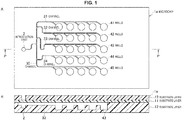
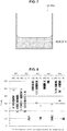
- FIG. 1 is a schematic view illustrating a configuration of a microchip 1a according to a first embodiment of the present technology.
- FIG. 1A is a top face schematic view
- FIG. 1B is a cross-sectional schematic view across the P-P cross-section of FIG. 1A .
- microchip for nucleic acid amplification reaction (hereinafter referred to as "microchip") denoted by reference numeral 1a includes, as an area into which a sample solution is introduced, an introduction part 2 into which a liquid such as a sample is externally introduced, wells 41 to 45 that serve as a reaction site for a nucleic acid amplification reaction, and channels 31 to 35 connecting the introduction part 2 and the respective wells. Further, as described below, reagents R1 and R2 that include at least a part of the substances required in the nucleic acid amplification reaction are contained in the wells 41 to 45 (reagents R1 and R2 are not illustrated in FIG. 1B ). In FIG.
- sample solution refers to a solution that includes a nucleic acid such as DNA or RNA, which is a template nucleic acid that is the target of amplification in a nucleic acid amplification reaction.
- nucleic acid amplification reaction performed using the microchip according to the present technology may include a conventional PCR (polymerase chain reaction) that employs thermal cycling, as well as various isothermal amplification methods that do not involve thermal cycling.
- isothermal amplification methods include methods such as LAMP (loop-mediated isothermal amplification), SMAP (SMart Amplification Process), NASBA (nucleic acid sequence-based amplification), ICAN® (isothermal and chimeric primer-initiated amplification of nucleic acids), TRC (transcription-reverse transcription concerted), SDA (strand displacement amplification), TMA (transcription-mediated amplification), RCA (rolling circle amplification) and the like.
- LAMP loop-mediated isothermal amplification
- SMAP SMart Amplification Process
- NASBA nucleic acid sequence-based amplification
- ICAN® isothermal and chimeric primer-initiated amplification of nucleic acids
- TRC transcription-reverse
- nucleic acid amplification reaction widely includes nucleic acid amplification reactions that are based on varying temperature or constant temperature, which are directed to the amplification of nucleic acids. Further, such nucleic acid amplification reaction also include reactions that involve quantification of an amplified nucleic acid, such as a real-time PCR method.
- the microchip 1a is formed by bonding a substrate layer 11 on a substrate layer 12 on which the introduction part 2, the channels 31 to 35, and the wells 41 to 45 are formed, and then bonding a substrate layer 13 on the substrate layer 11 (refer to FIG. 1B ).
- the interior of the introduction part 2, the channels 31 to 35, and the wells 41 to 45 can be hermetically sealed at a pressure lower than atmospheric pressure (1/100 atmospheric pressure).
- the sample solution is sucked up due to the negative pressure inside the microchip when the sample solution is introduced. Consequently, the introduction of the sample solution into the microchip 1a in which micro channel structures are formed can be carried out in a shorter period of time.
- the substrate layers 12 and 13 are formed from a gas-impermeable material.
- a gas-impermeable material such as PC
- the sample solution introduced into the wells 41 to 45 can be prevented from being turned into a gas by the heat of the nucleic acid amplification reaction, and escaping (fluid loss) through the substrate layer 11.
- the substrate layers 12 and 13 is formed from a gas-impermeable material in order to prevent the entry of air from outside of the microchip 1a to maintain the internal negative pressure.
- Examples of the material forming the gas-impermeable substrate layers includes glass, plastics, metals, and ceramics.
- plastics include PMMA (polymethyl methacrylate acrylic resin), PC (polycarbonate), PS (polystyrene), PP (polypropylene), PE (polyethylene), PET (polyethylene terephthalate), diethylene glycol bis-allyl carbonate, SAN resin (styrene-acrylonitrile copolymer), MS resin (MMA-styrene copolymer), TPX (poly(4-methyl penten-1)), polyolefin, SiMA (siloxanyl methacrylate monomer)-MMA copolymer, SiMA-fluorine containing monomer copolymer, silicon macromer-(A)-HFBuMA (heptafluorobutyl methacrylate)-MMA terpolymer, disubstituted polyacetylene-based polymer and the like.
- plastics include PMMA (pol
- metals include aluminum, copper, stainless steel (SUS), silicon, titanium, tungsten and the like.
- ceramics include alumina (Al 2 O 3 ), nitrogen aluminum (AlN), silicon carbide (SiC), titanium oxide (TiO 2 ), zirconia oxide (ZrO 2 ), quartz and the like.
- the substrate layer 11 is preferably formed from an elastic material.
- a portion of a penetrating member, such as a needle can penetrate the introduction part 2 from outside the microchip 1a. If a syringe connected to the needle is pre-filled with the sample solution, and the substrate layer 11 is penetrated by that needle, the sealed introduction part 2 and the interior of the syringe are connected, and the sample solution can be introduced into the microchip 1a without air bubbles being formed.
- the sample solution in the syringe is automatically sucked into the introduction part 2.
- the penetrated location can be naturally sealed due to the self-sealing ability of the substrate layer 11.
- self-sealing ability natural sealing of the penetrated location of the needle due to elastic deformation of the substrate layer.
- the elastic material includes acrylic-based elastomer, urethane-based elastomer, fluorine-based elastomer, styrene-based elastomer, epoxy-based elastomer, and natural rubber, in addition to silicon-based elastomer such as polydimethylsiloxane (PDMS).
- PDMS polydimethylsiloxane
- the material for each of the substrate layers a material that is light transmissive and that has little optical error due to having little intrinsic fluorescence and a small wavelength dispersion.
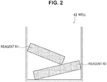
- a well 43 is schematically illustrated as a representative of the wells of the microchip 1a.
- the well 43 contains solid-phase reagents R1 and R2.
- the reagents R1 and R2 include at least a part of the substances required to obtain an amplified nucleic acid strand in a nucleic acid amplification reaction.
- oligonucleotide primer hereinafter sometimes also referred to as "primer”
- dNTPs nucleic acid monomer
- enzyme an enzyme
- reaction buffer solution that is complementary to at least a portion of the base sequence of the DNA, RNA and the like that is the amplification target.
- a probe including a label, such as a fluorescent label, for detecting the amplified nucleic acid strand a detection reagent that intercalates with double-stranded nucleic acid and the like may also be included in the reagents R1 and R2 as a substance that is used for detection of an amplified nucleic acid strand.
- reagent R1 and reagent R2 may be a different composition to each other.
- reagent R1 may be a reagent solution (a first reagent solution) that includes a primer but does not include an enzyme
- reagent R2 may be a reagent solution (a second reagent solution) that includes an enzyme but does not include a primer.
- reagent R1 may be the reagent solution (the second reagent solution) that includes an enzyme but does not include a primer
- reagent R2 may be the reagent solution (the first reagent solution) that includes a primer but does not include an enzyme.
- the composition of reagents R1 and R2 may be freely selected. It is noted that reagents R1 and R2 are not limited to the shapes illustrated in FIG. 2 . They may be any shape as long as they have a volume that can be contained in the well 43. Further, reagents R1 and R2 having the same composition may be contained in the plurality of wells provided in the microchip 1a, or reagents R1 and R2 having different compositions may be contained in each of the wells.
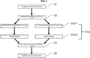
- reference symbol S1 represents a step of molding the substrate layer.
- the introduction part 2, channels 31 to 35, and wells 41 to 45 are formed on the substrate layer 12.
- the molding of the introduction part 2 and the like onto the substrate layer 12 can be carried out by a known technique.
- the molding can be carried out by wet etching or dry etching of a glass substrate layer, or by nano-printing, injection molding, or cutting of a plastic substrate layer.
- the substrate layer 12 and the like can be molded on the substrate layer 11, or some parts may be molded on the substrate layer 11, and the remaining parts molded on the substrate layer 12.
- reference symbol S2 represents a step of preparing a reagent solution.
- a liquid or a gel-like reagent solution is prepared based on the composition of the reagents R1 and R2 to be contained in the microchip 1a. It is sufficient if the reagent solution only includes at least a part of the substances that are required in the nucleic acid amplification reaction, and the composition of the reaction solution may be arbitrarily set. For example, a reagent R1 that includes only a primer and a reagent R2 that only includes an enzyme may be readied. Further, the number of types of reagent solution that are prepared is not limited to two. A single reagent solution may include just one type, or a plurality of types, of the substances required in the nucleic acid amplification reaction.
- primers including a different base sequence to a primer formed from a given base sequence are counted as a different type of primer. Namely, for a target nucleic acid that is the target of amplification, a primer set pairing a primer designed for a base sequence of one nucleic acid strand with a primer designed for the base sequence of that complementary strand is considered as including two types of primer.
- the definition of these primer types is the same in the below-described second and third embodiments.
- a reagent solution that includes a primer but does not include an enzyme and a reagent solution that includes an enzyme but does not include a primer because this means the primer and the enzyme do not mix until the sample solution introduced when the nucleic acid amplification reaction is started reaches the well, which suppresses non-specific amplification of the nucleic acid by primer dimers.
- the primer-containing reagent solution includes two or more types of primer.
- the reagent solution preparation step S2 it is preferred to hold the reagent solutions, and the primer solution and enzyme solution added to the reaction solutions, at a cool temperature.
- This holding of the reagent solutions and the like at a cool temperature can be carried out by placing the container containing the reagent solutions and the like on ice, or by placing the equipment holding the tubes of an aluminum block and the like in advance in a freezer, and using in a cooled state.
- reference symbol S3a represents a step of solidifying the reagent solutions.
- the plurality of reagent solutions readied in preparation step S2 are solidified. Namely, in this step the reagent solutions are dried to produce solid-phase reagents R1 and R2.
- Fixing step S3a will be described by dividing it into two stages, which are, as illustrated in FIG. 3 , in order, a "reagent solution dropwise addition” step S3a-1, and a "freeze-drying" step S3a-2.
- FIG. 3 is a flowchart illustrating a case in which two types of reagent solution were readied in preparation step S2.
- a reagent solution prepared in the above-described reagent solution preparation step S2 is added dropwise to a solidification container to be used in solidification step S3a. If a plurality of types of reagent solution were readied in preparation step S2, each of these reagent solutions is individually added dropwise to the solidification container, and individually solidified. Further, even for a case in which reagents R1 with the same composition are to be contained in the plurality of wells 41 to 45 of the microchip 1a, a number of solidification containers that matches the number of wells are readied, and the reagent solutions are added dropwise to the respective solidification container.
- the solidification container may be any material, it is preferred that the solidification container is capable of withstanding the temperature and air pressure set in the subsequent freeze-drying step S3a-2.
- the above-described reagent solution added dropwise to the container us solidified by drying.
- the drying method for example, freeze-drying is preferred.
- the freeze-drying includes steps such as pre-freezing, primary drying (sublimation freezing), and secondary drying (removal of bound water).
- the pre-freezing can be carried out if the freezing temperature is at the eutectic point (temperature at which the reagent solution freezes) or lower.
- the reagent solution frozen in the pre-freezing step is dried.
- the degree of vacuum in the primary drying is desirably 100 Pa or less, for example.
- the boiling point of water at 100 Pa is about -20°C, which is close to the above-described eutectic point of the reagent solution. Accordingly, dissolution during the drying process is prevented.
- the degree of vacuum in the primary drying can be appropriately selected based on the eutectic point of the prepared reagent solution.
- water in a molecular state that is adhered to the components included in the reagent solution after the primary drying is removed.
- the reagent solution can be heated to a temperature at which the components in the reagent solution are not deactivated, denatured or the like, to increase the degree of dryness of the reagent solution.
- the drying method of the solidification step S3a is not limited to freeze-drying.
- reference symbol S4 represents a step of containing the reagents R1 and R2.
- the solid-phase reagents R1 and R2 produced in solidification containers in the above-described reagent solution solidification step S3a are removed from the solidification containers, and contained in any one of the wells formed in the substrate layer in the substrate layer molding step S1.
- the reagents R1 and R2 may be contained in any of the plurality of wells provided on the substrate layer 12, either in one well or in a plurality of wells. Further, the number and type of reagents R1 and R2 contained in one well can be freely set.
- Reagents R1 and R2 with the same composition or reagents R1 and R2 with different compositions may be contained in a plurality of wells. If a primer is included in reagent R1 or in reagent R2, it is preferred that there is two or more types of primer included in one reagent. For example, a reagent R1 and a reagent R2 each containing different primers may be readied, and the reagents R1 and R2 contained so that they are arranged in separate wells among the plurality of wells provided in the microchip 1a. In such a case, the amplification of a plurality of nucleic acid strands having different base sequences can be analyzed in a single nucleic acid amplification reaction, so that analysis using the microchip 1a is simpler.
- reference symbol S5 represents a substrate layer bonding step.
- another substrate layer is bonded on either of the substrate layers in which the reagents R1 and R2 were contained.
- the bonding of the substrate layers 11, 12, and 13 can be performed by a known method, such as thermal fusion bonding, with an adhesive, anodic bonding, bonding using a pressure-sensitive adhesive sheet, plasma activation bonding, ultrasonic bonding and the like. Further, by carrying out the bonding of the substrate layers 11, 12 and 13 under a pressure lower than atmospheric pressure, the respective areas of the introduction part 2, the channels 31 to 35, and the wells 41 to 45 into which the sample solution is introduced can be made to have a pressure lower than atmospheric pressure (e.g., 1/100 atmospheric pressure).
- the substrate layer 11 When a material, such as PDMS, that in addition to being elastic is also impermeable to gases, is used for the substrate layer 11 that seals the wells 41 to 45, if these layers are left under a negative pressure (vacuum) after the substrate layers 11 and 12 have been bonded, the air that is present in the respective areas, such as the introduction part 2, passes through the substrate layer 11. Consequently, the interior of the microchip 1a can be made to have a pressure lower than atmospheric pressure (a vacuum). It is noted that the step of making the interior of the microchip 1a have a pressure lower than atmospheric pressure is not a necessary step in the method for fabricating the microchip according to an embodiment of the present technology.
- reagents R1 and R2 that include a part of the substances required for the nucleic acid amplification reaction are contained in advance in the wells 41 to 45 that are analysis sites. Consequently, a nucleic acid amplification reaction can be started just by supplying the remaining substances required for the nucleic acid amplification reaction and the sample solution including the target nucleic acid amplification strand to the wells 41 to 45. Further, by containing the plurality of solid-phase reagents R1 and R2 in wells 41 to 45, the plurality of substances required for the nucleic acid amplification reaction can be held in the microchip 1a in a separated state until the start of analysis.
- the method for fabricating the microchip for nucleic acid amplification reaction according to the present technology enables the fabrication of a microchip for nucleic acid amplification reaction that is capable of simple yet highly accurate analysis.
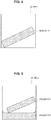
- a well 43 is schematically illustrated as a representative for a reagent R that is contained in the wells of a microchip 1a-2 according to a modified embodiment of the first embodiment. Except for the composition of the reagent R contained in the respective wells, such as the wells 43, the microchip 1a-2 is the same as in the first embodiment. The parts that are the same as in the first embodiment are denoted with the same reference numerals, and a description thereof is omitted here. Further, the material of the substrate layers 11, 12, and 13 configuring the microchip 1a-2 is the same as the substrate layers denoted with the same reference numerals for the microchip 1a.
- reagent R is contained in the wells 43 of the microchip 1a-2.
- the fabrication steps of the microchip 1a-2 are the same as the flowchart illustrated in FIG. 3 , except for the type of reagent solution that is prepared. Accordingly, a description of the fabrication steps will be omitted.
- the reagent R contained in the microchip 1a-2 may be a single type.
- a reagent R including an enzyme may be contained in well 43, and the other components required for the nucleic acid amplification reaction, such as a primer, may be introduced into the microchip 1a-2 by mixing with the sample solution when the nucleic acid amplification reaction starts.
- the microchip 1a-2 a part of the components required for a nucleic acid amplification reaction are contained in advance in the wells 41 to 45, so that the components included in the reagent R in the wells can be kept separate from the other components until the sample solution is introduced into the wells. Consequently, for example, an enzyme and a primer can be separated until the nucleic acid amplification reaction starts, so that non-specific nucleic acid amplification caused by primer dimers and the like is suppressed, which enables highly accurate analysis using the microchip 1a-2.
- a well 43 is schematically illustrated as a representative for reagents R1 and R2 contained in the wells of a microchip 1b according to a second embodiment of the present technology. Except for the composition of the reagents R1 and R2 contained in the respective wells, such as the wells 43, the microchip 1b is the same as in the first embodiment. The parts that are the same as in the first embodiment are denoted with the same reference numerals, and a description thereof is omitted here. Further, the material of the substrate layers 11, 12, and 13 configuring the microchip 1b is the same as the substrate layers denoted with the same reference numerals for the microchip 1a.
- the reagents R1 and R2 illustrated in FIG. 5 are solid-phase reagents that include at least a part of the substances required for a nucleic acid amplification reaction. Since the composition of the reagents R1 and R2 is the same as that of the reagents R1 and R2 contained in the microchip 1a, a description thereof is omitted. The difference between the reagents R1 and R2 contained in the microchip 1b and the reagents R1 and R2 contained in the microchip 1a is that a part of the reagents contained in the wells 43 is fixed in the well (refer to FIG. 5 ).
- the method for fabricating the microchip 1b will now be described with reference to the flowchart illustrated in FIG. 6 . Since the substrate layer molding step S1, the reagent solution preparation step S2, and the substrate layer bonding step S5, respectively, are the same as in the first embodiment, a description thereof will be omitted.
- the reagent solution fixing step S3b and the reagent containment step S4 will be described.
- reference symbol S3b represents a step of fixing the reagent solutions.
- this step among the plurality of types of reagent solution readied in the preparation step S2, one type of reagent solution is fixed in the wells 43. Namely, a reagent solution is dried in the wells 43, and the dried reagent solution is fixed in the well.
- the fixing step S3b will be described in order of a "reagent solution dropwise addition" step S3b-1 and a "vacuum-drying" step S3b-2 as illustrated in FIG. 6 . Further, in the fabrication of the microchip 1b, the other reagent solution not used in the reagent solution fixing step S3b is turned into a solid state by the reagent solution solidification step S3a in the same manner as in the first embodiment.
- one type of reagent solution is added dropwise to each well formed in the substrate layer 12 and the like in molding step S1. At this stage, it is preferred that the substrate layer 12 in which the wells are formed has been cooled.
- the reagent solution is dried by placing the substrate layer 12 onto which the above-described reagent solution was added dropwise under a vacuum (600 to 1,000 Pa).
- a vacuum 600 to 1,000 Pa
- the drying method may also be carried out by air drying, for example, according to the nature of the substances included in the reagent solution.
- reference symbol S4 represents a reagent containment step.
- the reagent R2 is present in the wells 43 in the microchip 1b.
- the reagent R1 readied in the reagent solution solidification step S3a is separately contained in the well in which this reagent R2 has been fixed.
- the solidified reagent solution R1 to be contained in the microchip 1b is not limited to being one type, it may be freely selected.
- reagents R1 and R2 that include a part of the substances required for a nucleic acid amplification reaction are held in advance in the wells 41 to 45 that are analysis sites. Consequently, similar to the microchip 1a, when performing a nucleic acid amplification reaction using the microchip 1b, the nucleic acid amplification reaction can be simply performed by introducing just the remaining substances required for the nucleic acid amplification reaction and the sample solution including the target nucleic acid amplification strand into the wells 41 to 45.
- the components included in the plurality of solid-phase reagents R1 and R2 having different compositions that are held in the wells 41 to 45 and that have difference compositions can be maintained in separate states until the start of the nucleic acid amplification reaction. Consequently, by including, for example, an enzyme and a primer as the components included in the reagent R1 and reagent R2, respectively, non-specific amplification of the nucleic acid due to the occurrence of primer dimers can be suppressed.
- a well 43 is schematically illustrated as a representative for a reagent R that is contained in the wells of a microchip 1c according to a third embodiment. Except for the composition of the reagent R contained in the respective wells, such as the wells 43, the microchip 1c is the same as in the first embodiment. The parts that are the same as in the first embodiment are denoted with the same reference numerals, and a description thereof is omitted here. Further, the material of the substrate layers 11, 12, and 13 configuring the microchip 1c is the same as the substrate layers denoted with the same reference numerals for the microchip 1a.
- the reagent R which includes at least a part of the substances required to obtain a nucleic acid amplification strand in a nucleic acid amplification reaction, is fixed in the wells 43 of the microchip 1c ( FIG 7 ).
- the components required for the nucleic acid amplification reaction that are included in the reagent R may be a single type, or a plurality of types.
- the substrate layer molding step S1 the reagent solution preparation step S2, and the substrate layer bonding step S5 are the same as in the first embodiment, a description thereof will be omitted.
- the step of fixing a reagent solution in the wells 43 is carried out by adding a reagent solution prepared to a predetermined composition dropwise to each well provided on the substrate layer 12, and fixing the reagent solution in the wells 43 by vacuum-drying or the like.
- the prepared reagent solution is stored at a cool temperature.
- the substrate layer 12 in which the respective wells are formed is also stored at a cool temperature.
- the equipment holding the substrate layer 12, such as an aluminum block may be cooled in advance in a freezer, and the dropwise addition of the reagent solution carried out by placing the substrate layer 12 on the cooled equipment.
- the reagent R fixed in the wells 43 and the like may be a single type, or may be reagents R1 and R2 having different compositions.
- the dropwise addition of the reagent solution may be carried out by adding either of the reagent solutions dropwise into the wells 43 and fixing by vacuum-drying or the like, then adding dropwise the next reagent solution onto the fixed reagent R1 and drying, and then repeating these steps.
- aspects of the present technology may include the following.
- microchips Four types of microchip whose methods and the like of producing the reagent to be contained were different were used as the microchips used in the present example. For all four types of microchip, substrates made from PDMS and glass were used as materials. Further, as the reagent required for the nucleic acid amplification reaction performed in the present example, four types of primer used for amplification of influenza type A, Bst DNA polymerase, dNTPs, and a reaction buffer solution were readied. The steps from the reagent solution preparation step until the containment step will be described below for each microchip.
- microchip 1 As a comparative example of the microchip for nucleic acid amplification reaction according to the present technology, microchip 1 (hereinafter referred to as "M1") was fabricated.
- M1 a reagent solution including four types of primer, Bst DNA polymerase, dNTPs, and a reaction buffer solution was prepared.
- 1.2 ⁇ L of the reagent solution was added dropwise into the wells formed in the substrate layer, and the reagent solution in the wells was fixed by a vacuum-drying treatment (about 1,000 Pa) of about 2 hours.
- Microchip 2 (hereinafter referred to as "M2") is a microchip in which a solidified reagent is contained in the wells.
- M2 the preparation of a reagent solution including four types of primer, Bst DNA polymerase, dNTPs, and a reaction buffer solution was carried out under cooling by placing the solidification container over ice.
- the reagent solution was frozen by leaving the solidification container containing 1.2 ⁇ L of reagent solution for 6 hours at -40°C. After the reagent solution had frozen, the solidification container was set in a freeze dryer (FDU-2200, EYELA).
- the reagent solution was dried for 12 hours or more in a vacuum (about 6 to 8 Pa) with the reagent solution kept in a frozen state. Then, the temperature of the drying chamber was set to 30°C, and the reagent solution was dried for a further 6 hours or more. The reagent solidified by the freeze-drying was removed from the solidification container, and placed in the wells formed in the substrate layer.
- Microchip 3 (hereinafter referred to as "M3”) is a microchip in which a plurality of solidified reagents containing different substances are contained in the wells.
- M3 a reagent solution including, among the components required for the nucleic acid amplification reaction of four types of primer, Bst DNA polymerase, dNTPs, and a reaction buffer solution, the primers (hereinafter referred to as "FluA”) was prepared while cooling.
- a reagent solution including the Bst DNA polymerase, the dNTPs, and the reaction buffer solution (hereinafter referred to as "RM”) was prepared while cooling.
- the prepared reagent solutions were added dropwise (0.4 ⁇ l for FluA and 0.8 ⁇ l for RM) into separate solidification containers.
- the respective reagent solutions in the solidification containers were solidified by freeze-drying in the same manner as for M2.
- the solidified FluA and RM were removed from the solidification containers, and placed in each of the wells formed in the substrate layer so that both FluA and RM were contained in each well.
- Microchip 4 (hereinafter referred to as "M4") is a microchip in which reagents containing different components were fixed in the wells over a plurality of times.
- the reagent solution FluA and the reagent solution RM were prepared in the same manner as M2.
- 0.4 ⁇ l of FluA was added dropwise into the wells, and fixed in the wells by vacuum-drying in the same manner as for M1.
- the substrate layer having the wells in which the FluA had been fixed was cooled and maintained at a low temperature, and in that state 0.8 ⁇ l of RM was added dropwise into the wells in which the FluA was fixed.
- Vacuum-drying was carried out again in the same manner as for M1 to fix the RM in the wells.
- the substrate layer having the wells in which the reagent was contained or had been fixed of the above four types of microchip was laminated with another substrate layer to seal the wells.
- the surface of each substrate layer was treated by oxygen plasma irradiation (O 2 : 10 cc, RF output: 100 W, RF irradiation time: 30 seconds) and bonded under a vacuum to complete the microchips M1 to M4.
- a nucleic acid amplification reaction was carried out using the microchips M1 to M4 fabricated by the above-described steps.
- a LAMP method was employed for the nucleic acid amplification.
- a sample solution was charged into M1 to M4, and the nucleic acid amplification reaction was carried out at 63°C.
- an influenza type A positive specimen positive control, hereinafter referred to as "PC”
- an influenza type A negative specimen negative control, hereinafter referred to as "NC”
- NTC non-template control
- Detection of the nucleic acid strands was carried out by fluorescence detection, and SYBR Green was used for the detection reagent.
- FIG. 8 shows the start of nucleic acid amplification in each of the microchips M1 to M4 for each sample solution.
- the nucleic acid amplification start time is defined as the time at which an amplification curve plotting the fluorescence intensity obtained by SYBR Green rises up and reaches a predetermined threshold.
- the M1' in FIG. 8 is a microchip fabricated by the same fabrication steps as for M1, and which was used in a nucleic acid amplification reaction in the same manner as M1.
- nucleic acid amplification was detected in the wells that the PC was introduced into for the microchips M1 to M4 (regarding M1, refer to M1') Namely, it was shown that the reagent contained in the wells was stored in a state that could be used in a nucleic acid amplification reaction. On the other hand, nucleic acid amplification was observed also for the microchips M1 to M4 into which the NC and the NTC had been introduced. This indicates that non-specific amplification of the nucleic acid strand occurred in the wells of the microchips M1 to M4.
- nucleic acid amplification reaction performed in the present example, specific amplification for a template nucleic acid strand of a nucleic acid was detected within 30 minutes of the start of the nucleic acid amplification reaction ( FIG. 8 ). Consequently, the fact that nucleic acid amplification occurred within 30 minutes of the reaction starting in the wells into which NC and NTC had been introduced, in which nucleic acid amplification should not occur, impairs analysis using the microchips.
- the start of non-specific nucleic acid amplification in M3 was more than 50 minutes after the start of the nucleic acid amplification reaction.
- the start of non-specific nucleic acid amplification in the comparative example M1 was detected about 20 minutes after the start of the reaction. From this result, it was shown that non-specific nucleic acid amplification is suppressed in the nucleic acid amplification reaction using M3.
- the start of non-specific nucleic acid amplification in M2 and M4 was, in some of the wells, after about 30 minutes had passed. Compared with the M3 results, in the results for M2 and M4 the start time of non-specific nucleic acid amplification was earlier. However, nucleic acid amplification was not deemed to have occurred for NTC and NC within 30 minutes of the start of the nucleic acid amplification reaction. From this result, it was shown that in M2 and M4, non-specific nucleic acid amplification was suppressed more than in M1 (comparative example). Further, the suppression effect of non-specific nucleic acid amplification was about the same in M2 and M4.
- microchip (M2) that contained a solid-phase reagent including an enzyme and a primer
- microchip (M4) fabricated by adding a reagent solution including an enzyme dropwise into wells in which a reagent including a primer had been fixed
- the suppression of non-specific nucleic acid amplification was observed. This indicates that non-specific nucleic acid amplification is suppressed in a nucleic acid amplification reaction that uses a reagent that was dried after the mixing of a cooled enzyme and a primer in the microchip fabrication steps.
- the microchip nucleic acid amplification reaction according to the present technology not only enables analysis to be carried out simply just by the introduction of a sample solution and the like, but since non-specific nucleic acid amplification is suppressed, also enables highly accurate analysis.
- the microchip for nucleic acid amplification reaction according to the present technology analysis based on nucleic acid amplification can be carried out simply and accurately. Consequently, the microchip for nucleic acid amplification reaction according to the present technology can be used as a device that performs nucleic acid amplification for clinical genotyping and contagion determination.
Claims (2)
- Procédé pour la fabrication d'une micropuce pour une réaction d'amplification d'acide nucléique, le procédé comprenant :une étape de solidification (S3a) consistant à faire sécher dans un récipient de solidification une pluralité de solutions de réactifs comprenant au moins une partie de substances requises pour une réaction d'amplification d'acide nucléique, l'étape de solidification comprenant une étape consistant à lyophiliser (S3a-2) la pluralité de solutions de réactifs ;une étape de confinement (S4) consistant à disposer les solutions de réactifs solidifiées dans des puits qui servent de sites de réaction pour une réaction d'amplification d'acide nucléique ; etune étape de préparation (S2) consistant à préparer, avant l'étape de solidification, la pluralité des solutions de réactifs qui ont différentes compositions,dans lequel la pluralité de solutions de réactifs comprennent une première solution de réactifs qui comprend une amorce oligonucléotidique mais pas une enzyme et une seconde solution de réactifs qui comprend une enzyme n'est pas une amorce oligonucléotidique,dans lequel pendant l'étape de confinement, la première solution de réactifs et la seconde solution de réactifs sont toutes deux disposées dans chaque puits,dans lequel, pour chaque solution de réactifs de la pluralité de solutions de réactifs, l'étape de lyophilisation comprend :une étape de congélation effectuée à une température inférieure ou égale au point de congélation de cette solution de réactifs de la pluralité de solutions de réactifs ;une étape de séchage primaire dans laquelle la solution de réactifs de la pluralité de solutions de réactifs congelée dans l'étape de congélation préalable est séchée ; etune étape de séchage secondaire dans laquelle de l'eau dans un état moléculaire qui a adhéré aux constituants inclus dans la solution de réactifs de la pluralité de solutions de réactifs après le séchage primaire est enlevée etdans lequel l'étape consistant à effectuer une lyophilisation est effectuée individuellement pour chaque solution de réactifs de la pluralité de solutions de réactifs.
- Procédé pour la fabrication d'une micropuce pour une réaction d'amplification d'acide nucléique selon la revendication 1, dans lequel l'étape de confinement comprend une étape consistant à confiner la première solution de réactifs qui a été solidifiée et qui comprend deux ou plus de deux sortes d'amorce oligonucléotidique dans chacun des puits d'une pluralité des puits.
Applications Claiming Priority (2)
| Application Number | Priority Date | Filing Date | Title |
|---|---|---|---|
| JP2012052322 | 2012-03-08 | ||
| PCT/JP2013/050652 WO2013132891A1 (fr) | 2012-03-08 | 2013-01-16 | Procédé pour produire une micropuce pour utilisation dans une réaction d'amplification d'acide nucléique |
Publications (3)
| Publication Number | Publication Date |
|---|---|
| EP2824172A1 EP2824172A1 (fr) | 2015-01-14 |
| EP2824172A4 EP2824172A4 (fr) | 2015-11-04 |
| EP2824172B1 true EP2824172B1 (fr) | 2017-09-06 |
Family
ID=49116378
Family Applications (1)
| Application Number | Title | Priority Date | Filing Date |
|---|---|---|---|
| EP13758540.2A Active EP2824172B1 (fr) | 2012-03-08 | 2013-01-16 | Procédé pour produire une micropuce pour utilisation dans une réaction d'amplification d'acide nucléique |
Country Status (8)
| Country | Link |
|---|---|
| US (1) | US9545630B2 (fr) |
| EP (1) | EP2824172B1 (fr) |
| JP (1) | JP5987895B2 (fr) |
| KR (1) | KR20140143139A (fr) |
| CN (1) | CN104160011A (fr) |
| IN (1) | IN2014MN01628A (fr) |
| RU (1) | RU2014135538A (fr) |
| WO (1) | WO2013132891A1 (fr) |
Families Citing this family (4)
| Publication number | Priority date | Publication date | Assignee | Title |
|---|---|---|---|---|
| WO2017161053A1 (fr) * | 2016-03-15 | 2017-09-21 | Abbott Laboratories | Systèmes et procédés pour analyse automatisée |
| WO2018109829A1 (fr) * | 2016-12-13 | 2018-06-21 | 栄研化学株式会社 | Micropuce |
| CN110885902B (zh) * | 2018-09-10 | 2022-10-21 | 北京亿森宝生物科技有限公司 | 用于检测猪蓝耳病毒并鉴别从中猪蓝耳病毒高致病经典变异株的冻干微芯片、试剂盒及方法 |
| CN110885899B (zh) * | 2018-09-10 | 2023-04-14 | 中国动物疫病预防控制中心(农业部屠宰技术中心) | 用于鉴别16种禽病病原冻干微芯片、试剂盒及方法 |
Family Cites Families (15)
| Publication number | Priority date | Publication date | Assignee | Title |
|---|---|---|---|---|
| JPH0775518B2 (ja) | 1989-09-29 | 1995-08-16 | 勝 大鶴 | ▲高▼血圧、▲高▼脂血症、肥満の予防及び治療に有効な飲食用キノコタンパク質及びその抽出方法 |
| US5556771A (en) * | 1995-02-10 | 1996-09-17 | Gen-Probe Incorporated | Stabilized compositions of reverse transcriptase and RNA polymerase for nucleic acid amplification |
| JPH08291078A (ja) | 1995-04-21 | 1996-11-05 | M I O:Kk | 高血圧及び高脂血症の予防・治療に有効で且つ抗腫瘍作用を有する飲食用キノコタンパク質、及び肥満の予防・治療に有効で且つ抗腫瘍作用を有する飲食用キノコタンパク質、並びにそれらの抽出方法 |
| JPH10234822A (ja) | 1997-02-28 | 1998-09-08 | Material Eng Tech Lab Inc | 凍結乾燥用容器 |
| JP3626986B2 (ja) | 1999-05-19 | 2005-03-09 | 有限会社つくば食料科学研究所 | 凍結乾燥方法、装置および凍結乾燥物 |
| US6875619B2 (en) * | 1999-11-12 | 2005-04-05 | Motorola, Inc. | Microfluidic devices comprising biochannels |
| ES2180416B1 (es) * | 2001-03-12 | 2004-06-01 | BIOTOOLS BIOTECHNOLOGICAL & MEDICAL LABORATORIES, S.A. | Procedimiento para la preparacion de mezclas de reaccion estabilizadas, total o parcialmente desecadas, que comprenden, al menos, una enzima, mezclas de reaccion y kits que las contienen. |
| GB0414815D0 (en) * | 2004-07-02 | 2004-08-04 | Secr Defence | Method for stabilising reagents which are useful for nucleic acid amplification |
| CN100460013C (zh) | 2006-09-05 | 2009-02-11 | 重庆康卫生物科技有限公司 | 口服重组幽门螺杆菌疫苗及其制备方法 |
| WO2010036827A1 (fr) * | 2008-09-24 | 2010-04-01 | Straus Holdings Inc. | Procédé de détection d'analytes |
| WO2010074265A1 (fr) * | 2008-12-25 | 2010-07-01 | ユニバーサル・バイオ・リサーチ株式会社 | Procédé de prétraitement d'échantillon et procédé d'analyse de substance biologique |
| EP2391452B1 (fr) * | 2009-01-30 | 2015-06-17 | Gen-Probe Incorporated | Systèmes et procédés de détection d'un signal et d'application d'énergie thermique à un élément de transmission de signal |
| JP5691187B2 (ja) | 2010-02-10 | 2015-04-01 | ソニー株式会社 | 核酸増幅反応用マイクロチップ及びその製造方法 |
| JP5786295B2 (ja) * | 2010-06-22 | 2015-09-30 | ソニー株式会社 | 核酸等温増幅反応用マイクロチップ及びその製造方法並びに核酸等温増幅方法 |
| JP2012080870A (ja) | 2010-09-16 | 2012-04-26 | Sony Corp | 核酸定量方法及び核酸増幅反応用マイクロチップ |
-
2013
- 2013-01-16 EP EP13758540.2A patent/EP2824172B1/fr active Active
- 2013-01-16 CN CN201380012088.2A patent/CN104160011A/zh active Pending
- 2013-01-16 US US14/378,588 patent/US9545630B2/en active Active
- 2013-01-16 KR KR1020147023987A patent/KR20140143139A/ko not_active Application Discontinuation
- 2013-01-16 JP JP2014503511A patent/JP5987895B2/ja active Active
- 2013-01-16 IN IN1628MUN2014 patent/IN2014MN01628A/en unknown
- 2013-01-16 WO PCT/JP2013/050652 patent/WO2013132891A1/fr active Application Filing
- 2013-01-16 RU RU2014135538A patent/RU2014135538A/ru not_active Application Discontinuation
Non-Patent Citations (1)
| Title |
|---|
| None * |
Also Published As
| Publication number | Publication date |
|---|---|
| US20150017318A1 (en) | 2015-01-15 |
| WO2013132891A1 (fr) | 2013-09-12 |
| JPWO2013132891A1 (ja) | 2015-07-30 |
| EP2824172A4 (fr) | 2015-11-04 |
| RU2014135538A (ru) | 2016-03-20 |
| US9545630B2 (en) | 2017-01-17 |
| CN104160011A (zh) | 2014-11-19 |
| JP5987895B2 (ja) | 2016-09-07 |
| EP2824172A1 (fr) | 2015-01-14 |
| IN2014MN01628A (fr) | 2015-05-15 |
| KR20140143139A (ko) | 2014-12-15 |
Similar Documents
| Publication | Publication Date | Title |
|---|---|---|
| US9737887B2 (en) | Integrated sample preparation systems and stabilized enzyme mixtures | |
| TWI539001B (zh) | 快速多重擴增目標核酸的方法 | |
| EP2824172B1 (fr) | Procédé pour produire une micropuce pour utilisation dans une réaction d'amplification d'acide nucléique | |
| EP2464452A1 (fr) | Dispositif microfabriqué pour mesurer un analyte | |
| EP1458473A2 (fr) | Manipulation de fluide dans un systeme de chambre de reaction microfabrique | |
| EP3073273A1 (fr) | Plaque de micro chambre | |
| US20140011268A1 (en) | Microchip for chemical reaction and method for fabricating same | |
| US11904315B2 (en) | System and self-metering cartridges for point of care bioassays | |
| Ramalingam et al. | Real-time PCR array chip with capillary-driven sample loading and reactor sealing for point-of-care applications | |
| JP2014010109A (ja) | 核酸増幅反応用マイクロチップ | |
| JP5691187B2 (ja) | 核酸増幅反応用マイクロチップ及びその製造方法 | |
| CN111601661A (zh) | 具有排气微室的微流体装置 | |
| US20130102062A1 (en) | Microchip for nucleic acid amplification reaction and method of producing the same | |
| US11898197B2 (en) | System and self-metering cartridges for point of care bioassays | |
| AU2014259546A1 (en) | Integrated sample preparation systems and stabilized enzyme mixtures | |
| US20230173497A1 (en) | Nucleic acid amplification | |
| Rombach | Pre-storage of reagents for nucleic acid analysis in unit-use quantities for integration in Lab-on-a-chip test carriers | |
| 김준회 | MICROWELL-BASED QUANTITATIVE GENE EXPRESSION ANALYSIS FOR SINGLE-CELL APPLICATIONS |
Legal Events
| Date | Code | Title | Description |
|---|---|---|---|
| PUAI | Public reference made under article 153(3) epc to a published international application that has entered the european phase |
Free format text: ORIGINAL CODE: 0009012 |
|
| 17P | Request for examination filed |
Effective date: 20140908 |
|
| AK | Designated contracting states |
Kind code of ref document: A1 Designated state(s): AL AT BE BG CH CY CZ DE DK EE ES FI FR GB GR HR HU IE IS IT LI LT LU LV MC MK MT NL NO PL PT RO RS SE SI SK SM TR |
|
| AX | Request for extension of the european patent |
Extension state: BA ME |
|
| DAX | Request for extension of the european patent (deleted) | ||
| RA4 | Supplementary search report drawn up and despatched (corrected) |
Effective date: 20151001 |
|
| RIC1 | Information provided on ipc code assigned before grant |
Ipc: C12N 15/09 20060101ALI20150925BHEP Ipc: C12M 1/00 20060101AFI20150925BHEP Ipc: G01N 37/00 20060101ALI20150925BHEP |
|
| 17Q | First examination report despatched |
Effective date: 20160926 |
|
| STAA | Information on the status of an ep patent application or granted ep patent |
Free format text: STATUS: EXAMINATION IS IN PROGRESS |
|
| GRAP | Despatch of communication of intention to grant a patent |
Free format text: ORIGINAL CODE: EPIDOSNIGR1 |
|
| STAA | Information on the status of an ep patent application or granted ep patent |
Free format text: STATUS: GRANT OF PATENT IS INTENDED |
|
| INTG | Intention to grant announced |
Effective date: 20170327 |
|
| GRAS | Grant fee paid |
Free format text: ORIGINAL CODE: EPIDOSNIGR3 |
|
| GRAA | (expected) grant |
Free format text: ORIGINAL CODE: 0009210 |
|
| STAA | Information on the status of an ep patent application or granted ep patent |
Free format text: STATUS: THE PATENT HAS BEEN GRANTED |
|
| AK | Designated contracting states |
Kind code of ref document: B1 Designated state(s): AL AT BE BG CH CY CZ DE DK EE ES FI FR GB GR HR HU IE IS IT LI LT LU LV MC MK MT NL NO PL PT RO RS SE SI SK SM TR |
|
| REG | Reference to a national code |
Ref country code: GB Ref legal event code: FG4D |
|
| REG | Reference to a national code |
Ref country code: AT Ref legal event code: REF Ref document number: 925936 Country of ref document: AT Kind code of ref document: T Effective date: 20170915 Ref country code: CH Ref legal event code: EP |
|
| REG | Reference to a national code |
Ref country code: IE Ref legal event code: FG4D |
|
| REG | Reference to a national code |
Ref country code: DE Ref legal event code: R096 Ref document number: 602013026204 Country of ref document: DE |
|
| REG | Reference to a national code |
Ref country code: NL Ref legal event code: MP Effective date: 20170906 |
|
| REG | Reference to a national code |
Ref country code: LT Ref legal event code: MG4D |
|
| PG25 | Lapsed in a contracting state [announced via postgrant information from national office to epo] |
Ref country code: SE Free format text: LAPSE BECAUSE OF FAILURE TO SUBMIT A TRANSLATION OF THE DESCRIPTION OR TO PAY THE FEE WITHIN THE PRESCRIBED TIME-LIMIT Effective date: 20170906 Ref country code: HR Free format text: LAPSE BECAUSE OF FAILURE TO SUBMIT A TRANSLATION OF THE DESCRIPTION OR TO PAY THE FEE WITHIN THE PRESCRIBED TIME-LIMIT Effective date: 20170906 Ref country code: NO Free format text: LAPSE BECAUSE OF FAILURE TO SUBMIT A TRANSLATION OF THE DESCRIPTION OR TO PAY THE FEE WITHIN THE PRESCRIBED TIME-LIMIT Effective date: 20171206 Ref country code: FI Free format text: LAPSE BECAUSE OF FAILURE TO SUBMIT A TRANSLATION OF THE DESCRIPTION OR TO PAY THE FEE WITHIN THE PRESCRIBED TIME-LIMIT Effective date: 20170906 Ref country code: LT Free format text: LAPSE BECAUSE OF FAILURE TO SUBMIT A TRANSLATION OF THE DESCRIPTION OR TO PAY THE FEE WITHIN THE PRESCRIBED TIME-LIMIT Effective date: 20170906 |
|
| REG | Reference to a national code |
Ref country code: AT Ref legal event code: MK05 Ref document number: 925936 Country of ref document: AT Kind code of ref document: T Effective date: 20170906 |
|
| PG25 | Lapsed in a contracting state [announced via postgrant information from national office to epo] |
Ref country code: LV Free format text: LAPSE BECAUSE OF FAILURE TO SUBMIT A TRANSLATION OF THE DESCRIPTION OR TO PAY THE FEE WITHIN THE PRESCRIBED TIME-LIMIT Effective date: 20170906 Ref country code: GR Free format text: LAPSE BECAUSE OF FAILURE TO SUBMIT A TRANSLATION OF THE DESCRIPTION OR TO PAY THE FEE WITHIN THE PRESCRIBED TIME-LIMIT Effective date: 20171207 Ref country code: ES Free format text: LAPSE BECAUSE OF FAILURE TO SUBMIT A TRANSLATION OF THE DESCRIPTION OR TO PAY THE FEE WITHIN THE PRESCRIBED TIME-LIMIT Effective date: 20170906 Ref country code: RS Free format text: LAPSE BECAUSE OF FAILURE TO SUBMIT A TRANSLATION OF THE DESCRIPTION OR TO PAY THE FEE WITHIN THE PRESCRIBED TIME-LIMIT Effective date: 20170906 Ref country code: BG Free format text: LAPSE BECAUSE OF FAILURE TO SUBMIT A TRANSLATION OF THE DESCRIPTION OR TO PAY THE FEE WITHIN THE PRESCRIBED TIME-LIMIT Effective date: 20171206 |
|
| PG25 | Lapsed in a contracting state [announced via postgrant information from national office to epo] |
Ref country code: NL Free format text: LAPSE BECAUSE OF FAILURE TO SUBMIT A TRANSLATION OF THE DESCRIPTION OR TO PAY THE FEE WITHIN THE PRESCRIBED TIME-LIMIT Effective date: 20170906 |
|
| PG25 | Lapsed in a contracting state [announced via postgrant information from national office to epo] |
Ref country code: CZ Free format text: LAPSE BECAUSE OF FAILURE TO SUBMIT A TRANSLATION OF THE DESCRIPTION OR TO PAY THE FEE WITHIN THE PRESCRIBED TIME-LIMIT Effective date: 20170906 Ref country code: RO Free format text: LAPSE BECAUSE OF FAILURE TO SUBMIT A TRANSLATION OF THE DESCRIPTION OR TO PAY THE FEE WITHIN THE PRESCRIBED TIME-LIMIT Effective date: 20170906 Ref country code: PL Free format text: LAPSE BECAUSE OF FAILURE TO SUBMIT A TRANSLATION OF THE DESCRIPTION OR TO PAY THE FEE WITHIN THE PRESCRIBED TIME-LIMIT Effective date: 20170906 |
|
| PG25 | Lapsed in a contracting state [announced via postgrant information from national office to epo] |
Ref country code: IT Free format text: LAPSE BECAUSE OF FAILURE TO SUBMIT A TRANSLATION OF THE DESCRIPTION OR TO PAY THE FEE WITHIN THE PRESCRIBED TIME-LIMIT Effective date: 20170906 Ref country code: SM Free format text: LAPSE BECAUSE OF FAILURE TO SUBMIT A TRANSLATION OF THE DESCRIPTION OR TO PAY THE FEE WITHIN THE PRESCRIBED TIME-LIMIT Effective date: 20170906 Ref country code: SK Free format text: LAPSE BECAUSE OF FAILURE TO SUBMIT A TRANSLATION OF THE DESCRIPTION OR TO PAY THE FEE WITHIN THE PRESCRIBED TIME-LIMIT Effective date: 20170906 Ref country code: IS Free format text: LAPSE BECAUSE OF FAILURE TO SUBMIT A TRANSLATION OF THE DESCRIPTION OR TO PAY THE FEE WITHIN THE PRESCRIBED TIME-LIMIT Effective date: 20180106 Ref country code: EE Free format text: LAPSE BECAUSE OF FAILURE TO SUBMIT A TRANSLATION OF THE DESCRIPTION OR TO PAY THE FEE WITHIN THE PRESCRIBED TIME-LIMIT Effective date: 20170906 Ref country code: AT Free format text: LAPSE BECAUSE OF FAILURE TO SUBMIT A TRANSLATION OF THE DESCRIPTION OR TO PAY THE FEE WITHIN THE PRESCRIBED TIME-LIMIT Effective date: 20170906 |
|
| REG | Reference to a national code |
Ref country code: DE Ref legal event code: R097 Ref document number: 602013026204 Country of ref document: DE |
|
| PLBE | No opposition filed within time limit |
Free format text: ORIGINAL CODE: 0009261 |
|
| STAA | Information on the status of an ep patent application or granted ep patent |
Free format text: STATUS: NO OPPOSITION FILED WITHIN TIME LIMIT |
|
| PG25 | Lapsed in a contracting state [announced via postgrant information from national office to epo] |
Ref country code: DK Free format text: LAPSE BECAUSE OF FAILURE TO SUBMIT A TRANSLATION OF THE DESCRIPTION OR TO PAY THE FEE WITHIN THE PRESCRIBED TIME-LIMIT Effective date: 20170906 |
|
| 26N | No opposition filed |
Effective date: 20180607 |
|
| PG25 | Lapsed in a contracting state [announced via postgrant information from national office to epo] |
Ref country code: SI Free format text: LAPSE BECAUSE OF FAILURE TO SUBMIT A TRANSLATION OF THE DESCRIPTION OR TO PAY THE FEE WITHIN THE PRESCRIBED TIME-LIMIT Effective date: 20170906 |
|
| REG | Reference to a national code |
Ref country code: CH Ref legal event code: PL |
|
| PG25 | Lapsed in a contracting state [announced via postgrant information from national office to epo] |
Ref country code: FR Free format text: LAPSE BECAUSE OF NON-PAYMENT OF DUE FEES Effective date: 20180131 Ref country code: LU Free format text: LAPSE BECAUSE OF NON-PAYMENT OF DUE FEES Effective date: 20180116 |
|
| REG | Reference to a national code |
Ref country code: IE Ref legal event code: MM4A |
|
| REG | Reference to a national code |
Ref country code: FR Ref legal event code: ST Effective date: 20180928 |
|
| REG | Reference to a national code |
Ref country code: BE Ref legal event code: MM Effective date: 20180131 |
|
| PG25 | Lapsed in a contracting state [announced via postgrant information from national office to epo] |
Ref country code: BE Free format text: LAPSE BECAUSE OF NON-PAYMENT OF DUE FEES Effective date: 20180131 Ref country code: CH Free format text: LAPSE BECAUSE OF NON-PAYMENT OF DUE FEES Effective date: 20180131 Ref country code: LI Free format text: LAPSE BECAUSE OF NON-PAYMENT OF DUE FEES Effective date: 20180131 |
|
| PG25 | Lapsed in a contracting state [announced via postgrant information from national office to epo] |
Ref country code: IE Free format text: LAPSE BECAUSE OF NON-PAYMENT OF DUE FEES Effective date: 20180116 |
|
| PG25 | Lapsed in a contracting state [announced via postgrant information from national office to epo] |
Ref country code: MC Free format text: LAPSE BECAUSE OF FAILURE TO SUBMIT A TRANSLATION OF THE DESCRIPTION OR TO PAY THE FEE WITHIN THE PRESCRIBED TIME-LIMIT Effective date: 20170906 |
|
| PG25 | Lapsed in a contracting state [announced via postgrant information from national office to epo] |
Ref country code: MT Free format text: LAPSE BECAUSE OF NON-PAYMENT OF DUE FEES Effective date: 20180116 |
|
| PG25 | Lapsed in a contracting state [announced via postgrant information from national office to epo] |
Ref country code: TR Free format text: LAPSE BECAUSE OF FAILURE TO SUBMIT A TRANSLATION OF THE DESCRIPTION OR TO PAY THE FEE WITHIN THE PRESCRIBED TIME-LIMIT Effective date: 20170906 |
|
| PGFP | Annual fee paid to national office [announced via postgrant information from national office to epo] |
Ref country code: GB Payment date: 20200124 Year of fee payment: 8 |
|
| PG25 | Lapsed in a contracting state [announced via postgrant information from national office to epo] |
Ref country code: PT Free format text: LAPSE BECAUSE OF FAILURE TO SUBMIT A TRANSLATION OF THE DESCRIPTION OR TO PAY THE FEE WITHIN THE PRESCRIBED TIME-LIMIT Effective date: 20170906 Ref country code: HU Free format text: LAPSE BECAUSE OF FAILURE TO SUBMIT A TRANSLATION OF THE DESCRIPTION OR TO PAY THE FEE WITHIN THE PRESCRIBED TIME-LIMIT; INVALID AB INITIO Effective date: 20130116 |
|
| PG25 | Lapsed in a contracting state [announced via postgrant information from national office to epo] |
Ref country code: MK Free format text: LAPSE BECAUSE OF NON-PAYMENT OF DUE FEES Effective date: 20170906 Ref country code: CY Free format text: LAPSE BECAUSE OF FAILURE TO SUBMIT A TRANSLATION OF THE DESCRIPTION OR TO PAY THE FEE WITHIN THE PRESCRIBED TIME-LIMIT Effective date: 20170906 |
|
| PG25 | Lapsed in a contracting state [announced via postgrant information from national office to epo] |
Ref country code: AL Free format text: LAPSE BECAUSE OF FAILURE TO SUBMIT A TRANSLATION OF THE DESCRIPTION OR TO PAY THE FEE WITHIN THE PRESCRIBED TIME-LIMIT Effective date: 20170906 |
|
| GBPC | Gb: european patent ceased through non-payment of renewal fee |
Effective date: 20210116 |
|
| PG25 | Lapsed in a contracting state [announced via postgrant information from national office to epo] |
Ref country code: GB Free format text: LAPSE BECAUSE OF NON-PAYMENT OF DUE FEES Effective date: 20210116 |
|
| PGFP | Annual fee paid to national office [announced via postgrant information from national office to epo] |
Ref country code: DE Payment date: 20221220 Year of fee payment: 11 |
|
| P01 | Opt-out of the competence of the unified patent court (upc) registered |
Effective date: 20230527 |