EP2824005A1 - Antiblockier-bremsvorrichtung und -verfahren für fahrzeuge - Google Patents
Antiblockier-bremsvorrichtung und -verfahren für fahrzeuge Download PDFInfo
- Publication number
- EP2824005A1 EP2824005A1 EP13755722.9A EP13755722A EP2824005A1 EP 2824005 A1 EP2824005 A1 EP 2824005A1 EP 13755722 A EP13755722 A EP 13755722A EP 2824005 A1 EP2824005 A1 EP 2824005A1
- Authority
- EP
- European Patent Office
- Prior art keywords
- vehicle
- wheel
- antilock
- braking
- brake
- Prior art date
- Legal status (The legal status is an assumption and is not a legal conclusion. Google has not performed a legal analysis and makes no representation as to the accuracy of the status listed.)
- Withdrawn
Links
Images


Classifications
-
- B—PERFORMING OPERATIONS; TRANSPORTING
- B60—VEHICLES IN GENERAL
- B60T—VEHICLE BRAKE CONTROL SYSTEMS OR PARTS THEREOF; BRAKE CONTROL SYSTEMS OR PARTS THEREOF, IN GENERAL; ARRANGEMENT OF BRAKING ELEMENTS ON VEHICLES IN GENERAL; PORTABLE DEVICES FOR PREVENTING UNWANTED MOVEMENT OF VEHICLES; VEHICLE MODIFICATIONS TO FACILITATE COOLING OF BRAKES
- B60T8/00—Arrangements for adjusting wheel-braking force to meet varying vehicular or ground-surface conditions, e.g. limiting or varying distribution of braking force
- B60T8/32—Arrangements for adjusting wheel-braking force to meet varying vehicular or ground-surface conditions, e.g. limiting or varying distribution of braking force responsive to a speed condition, e.g. acceleration or deceleration
- B60T8/321—Arrangements for adjusting wheel-braking force to meet varying vehicular or ground-surface conditions, e.g. limiting or varying distribution of braking force responsive to a speed condition, e.g. acceleration or deceleration deceleration
- B60T8/3225—Systems specially adapted for single-track vehicles, e.g. motorcycles
-
- B—PERFORMING OPERATIONS; TRANSPORTING
- B60—VEHICLES IN GENERAL
- B60T—VEHICLE BRAKE CONTROL SYSTEMS OR PARTS THEREOF; BRAKE CONTROL SYSTEMS OR PARTS THEREOF, IN GENERAL; ARRANGEMENT OF BRAKING ELEMENTS ON VEHICLES IN GENERAL; PORTABLE DEVICES FOR PREVENTING UNWANTED MOVEMENT OF VEHICLES; VEHICLE MODIFICATIONS TO FACILITATE COOLING OF BRAKES
- B60T8/00—Arrangements for adjusting wheel-braking force to meet varying vehicular or ground-surface conditions, e.g. limiting or varying distribution of braking force
- B60T8/17—Using electrical or electronic regulation means to control braking
- B60T8/176—Brake regulation specially adapted to prevent excessive wheel slip during vehicle deceleration, e.g. ABS
- B60T8/1761—Brake regulation specially adapted to prevent excessive wheel slip during vehicle deceleration, e.g. ABS responsive to wheel or brake dynamics, e.g. wheel slip, wheel acceleration or rate of change of brake fluid pressure
- B60T8/17616—Microprocessor-based systems
-
- B—PERFORMING OPERATIONS; TRANSPORTING
- B60—VEHICLES IN GENERAL
- B60T—VEHICLE BRAKE CONTROL SYSTEMS OR PARTS THEREOF; BRAKE CONTROL SYSTEMS OR PARTS THEREOF, IN GENERAL; ARRANGEMENT OF BRAKING ELEMENTS ON VEHICLES IN GENERAL; PORTABLE DEVICES FOR PREVENTING UNWANTED MOVEMENT OF VEHICLES; VEHICLE MODIFICATIONS TO FACILITATE COOLING OF BRAKES
- B60T8/00—Arrangements for adjusting wheel-braking force to meet varying vehicular or ground-surface conditions, e.g. limiting or varying distribution of braking force
- B60T8/32—Arrangements for adjusting wheel-braking force to meet varying vehicular or ground-surface conditions, e.g. limiting or varying distribution of braking force responsive to a speed condition, e.g. acceleration or deceleration
- B60T8/34—Arrangements for adjusting wheel-braking force to meet varying vehicular or ground-surface conditions, e.g. limiting or varying distribution of braking force responsive to a speed condition, e.g. acceleration or deceleration having a fluid pressure regulator responsive to a speed condition
- B60T8/40—Arrangements for adjusting wheel-braking force to meet varying vehicular or ground-surface conditions, e.g. limiting or varying distribution of braking force responsive to a speed condition, e.g. acceleration or deceleration having a fluid pressure regulator responsive to a speed condition comprising an additional fluid circuit including fluid pressurising means for modifying the pressure of the braking fluid, e.g. including wheel driven pumps for detecting a speed condition, or pumps which are controlled by means independent of the braking system
- B60T8/4004—Repositioning the piston(s) of the brake control means by means of a fluid pressurising means in order to reduce the brake pressure
- B60T8/4009—Repositioning the piston(s) of the brake control means by means of a fluid pressurising means in order to reduce the brake pressure the brake control means being the wheel cylinders
-
- B—PERFORMING OPERATIONS; TRANSPORTING
- B60—VEHICLES IN GENERAL
- B60T—VEHICLE BRAKE CONTROL SYSTEMS OR PARTS THEREOF; BRAKE CONTROL SYSTEMS OR PARTS THEREOF, IN GENERAL; ARRANGEMENT OF BRAKING ELEMENTS ON VEHICLES IN GENERAL; PORTABLE DEVICES FOR PREVENTING UNWANTED MOVEMENT OF VEHICLES; VEHICLE MODIFICATIONS TO FACILITATE COOLING OF BRAKES
- B60T8/00—Arrangements for adjusting wheel-braking force to meet varying vehicular or ground-surface conditions, e.g. limiting or varying distribution of braking force
- B60T8/32—Arrangements for adjusting wheel-braking force to meet varying vehicular or ground-surface conditions, e.g. limiting or varying distribution of braking force responsive to a speed condition, e.g. acceleration or deceleration
- B60T8/54—Arrangements for adjusting wheel-braking force to meet varying vehicular or ground-surface conditions, e.g. limiting or varying distribution of braking force responsive to a speed condition, e.g. acceleration or deceleration by mechanical means
Definitions
- the invention relates to a vehicle antilock braking device and method.
- an antilock device By using an antilock device, safety and manipulability of the vehicle during braking can be increased, so the steering ability can be maintained and thus the risk of vehicle accident can be reduced.
- the antilock device can reduce the braking force, which causes locking up of the wheel, in an extreme short time to prevent wheel locking.
- antilock braking devices are designed for hydraulic braking systems.
- the structure and the operation principle of such an antilock braking device are based on sensors provided on vehicle wheels. Dynamic information of these sensors during vehicle braking is transmitted to a central processor of the vehicle, and the central processor processes the information and then controls, via a control system, the operation state of the hydraulic braking system in proper time to achieve antilock braking.
- Such an antilock braking system has a complex structure and a high cost, and can only be used in a vehicle having a hydraulic braking system, but is not applicable in a vehicle with a mechanical braking system.
- An object of the invention is to overcome the defects existed in the prior art by providing a vehicle antilock braking device and method for preventing wheel locking of a vehicle having a mechanical braking unit.
- a vehicle antilock braking device comprising:
- the invention also provides a vehicle antilock braking method for reducing or eliminating the braking force of a braking unit of a vehicle, the method comprising:
- a microcontroller is used for sensing the wheel locked condition and for controlling the generation of a mechanical pulling force for pulling the brake wire to reduce the braking force acted on a vehicle wheel which is in a wheel locked condition timely, so that the wheel locked condition can be eliminated effectively.
- the device of the invention has a simple structure and a low cost, and is applicable in antilocking of mechanical braking systems.
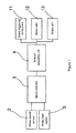
- the vehicle antilock braking device of the invention comprises a braking unit 1, a wheel speed sensor 2, a microcontroller 3 and an antilock actuating unit 4.
- the braking unit 1 may be a braking unit embodied in a mechanical manner, such as a drum brake, a wire brake or the like.
- the braking unit 1 mainly comprises a brake triggering component 11, a brake wire 12, a brake unit 13 and a brake light switch 5.
- the brake triggering component 11 may be in the form of a brake handle bar, a brake button, a brake pedal or the like.
- the brake unit 13 is a brake drum 13.
- the brake wire 12 has one end connected with the brake triggering component 11 and another end connected with brake drum 13 via a pulling bar 123.
- the brake wire 12 is provided with an adjusting screw 122 for adjusting the tightness of the brake wire 12.
- the pulling bar 123 is provided between the brake wire 12 and brake drum 13 for transmitting a force from the brake triggering component 11 to the brake drum 13.
- the driver may apply a force to push down the brake triggering component 11, and the force on the brake triggering component 11 is transmitted to the brake drum 13 to cause a brake shoe (not shown) to come into frictionally contact with the brake drum 13 to block the rotation of the vehicle wheel, so that vehicle braking is effected.
- front and back vehicle wheels of the vehicle are each mounted with a wheel speed sensor 2 for sensing a front or back wheel speed.
- the wheel speed sensor 2 may be a speed sensor of any type, such as an electro-magnetic sensor, a photo-electro sensor or the like.
- the wheel speed sensor 2 is a Hall sensor.
- teeth 23 of a tooth ring 22 of the vehicle pass the wheel speed sensor 2, the wheel speed sensor 2 sends out a wheel speed sensor signal, such as a rectangular pulse wave.
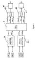
- the microcontroller 3 comprises an input end electrically connected with the wheel speed sensors 2 and the brake light switch 5 and receiving input signals including a front wheel speed sensor signal "WSS_F", a back wheel speed sensor signal “WSS_R” and brake light switch signals “BLS_F” and “BLS_R” of the front and back wheels. Based on the wheel speed sensor signals “WSS_F” and “WSS_R” and the brake light switch signals “BLS_F” and “BLS_R”, the microcontroller 3 judges whether a wheel locked condition occurs (including the case that a potential wheel locked condition will occur and the case that a wheel locked condition has already occurred) and sends out an antilocking control signal.
- the input signals are suitably adjusted in a wheel speed sensor signal adjusting module 21 and a brake light switch signal adjusting module 51 respectively, and are then input into the microcontroller 3.
- the microcontroller 3 is electrically connected with the brake light switch 5 and receives brake triggering signals, including the brake light switch signals "BLS_F” and "BLS_R", for sensing whether vehicle braking is conducted.
- the microcontroller 3 may further be connected with other components of the braking unit 1, such as the brake triggering component 11 or the brake wire 12, so that the brake triggering signal may be sent out from the brake triggering component 11 for determining the occurrence of vehicle braking.
- the microcontroller 3 comprises a speed calculating module 31, a slippage calculating module 32, a vehicle state machine 33 and a driving actuator module 34.
- the speed calculating module 31 comprises an input end electrically connected with the wheel speed sensor 2 and the brake light switch 5, and an output end electrically connected with the slippage calculating module 32 and the vehicle state machine 33 respectively.
- the speed calculating module 31 calculates and outputs front and back wheel decelerations "a_F” and "a_R” and a vehicle body speed "V".
- the slippage calculating module 32 comprises an input end electrically connected with the wheel speed sensor 2 and the speed calculating module 31, and an output end electrically connected with the vehicle state machine 33. Based on the wheel speed sensor signals "WSS_F” and “WSS_R” and the vehicle body speed "V", the slippage calculating module 32 calculates and outputs front and back wheel slippages "Slip_F” and "Slip_R". In another embodiment, the slippage calculating module 32 may directly calculate and output front and back wheel slippages "Slip_F” and "Slip_R” based on the front and back wheel decelerations "a_F” and "a_R” and the vehicle body speed "V".
- the vehicle state machine 33 comprises an input end electrically connected with the slippage calculating module 32 and the speed calculating module 31.
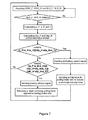
- the vehicle state machine 33 stores therein predetermined thresholds, including front and back wheel slippage thresholds "slip_thre_1” and “slip_thre_2” and front and back wheel deceleration thresholds "a_thre_1” and "a_thre_2", wherein “a_thre_1” ⁇ "a_thre_2".
- a_thre_1" is a negative value
- a_thre_2 is a positive value.
- “slip_thre_1” ⁇ "slip_thre_2".
- slip_thre_1" and “slip_thre_2” are both negative values.
- the values of the front and back wheel slippage thresholds “slip_thre_1” and “slip_thre_2” and the front and back wheel deceleration thresholds “a_thre_1” and “a_thre_2” can be set based on real need.
- the wheel slippages “Slip_F” and “Slip_R” and the front and back wheel decelerations “a_F” and “a_R” as input data are compared with the above mentioned predetermined thresholds respectively for judging whether a wheel locked condition presents.
- wheel locked condition means both a potential wheel locked condition that is to be occurred or a wheel locked condition that has been occurred.
- an antilock command signal "Command_ALD” is output for applying a pulling force for pulling the brake wire to reduce or eliminate the braking force.
- a locking release signal is output for reducing or even removing the pulling force applied to the brake wire.
- the driving actuator module 34 converts the received antilock command signal into the antilocking control signal "Command_ALD" and thus controls the antilock actuating unit 4 associated with the wheel which is in the locked condition.
- the antilock actuating unit 4 in responsive to the antilocking control signal from the microcontroller 3, the antilock actuating unit 4 generates a pulling force on the brake wire 12 for pulling it, to timely reduce or remove the braking force on the wheel which is in the locked condition.
- the antilock actuating unit 4 comprises an electric motor 41, a transmission box 42 and a rotation shaft 43.
- the electric motor 41 is connected with the microcontroller 3 via a driving module 40, the driving module 40 mainly comprising an H-bridge circuit for driving the electric motor 41 to rotate in either one of forward and backward directions based on a command.
- the driving module 40 receives the antilocking control signals "PWM_p" and “PWM_m” and “EN” from the microcontroller 3, it drives the electric motor 41 to rotate in the counter-clockwise direction at high rotational speed/low torque.
- the driving module 40 is a separate module. In another embodiment, the driving module 40 may be integrated into the microcontroller 3 or be provided in the electric motor 41, depending on real practice.
- the transmission box 42 comprises an input end 421 coupled to the electric motor 41, and an output end 422 coupled to the rotation shaft 43, and is configured to convert the counter-clockwise rotation at high rotational speed/low torque of the electric motor 41 to a rotation at low rotational speed/high torque which is to be transmitted to the rotation shaft 43 to drive the rotation shaft 43 to rotate in the clockwise direction at low rotational speed/high torque.
- the transmission box 42 comprises a set of 3-stage gears.
- the rotation directions of the electric motor 41 and the rotation shaft 43 are only illustrative.
- the transmission box 42 may comprise other types of transmission devices, and the electric motor 41 and the rotation shaft 43 may rotate in any directions respectively, only if the pulling force to be applied to the brake wire 12 for reducing or removing the braking force on the wheel which is in the locked condition can be generated effectively.
- the brake wire 12 is provided with a connecting member 121, the connecting member 121 comprising one end fixed to the brake wire 12 and another end fixed to the rotation shaft 43 to couple the rotation shaft 43 with the brake wire 12.
- the rotation shaft 43 rotates in the clockwise direction with a high torque which generates a pulling force for pulling the brake wire 12 to reduce or eliminate the contact frictional force between the brake shoe and the brake drum 13, as a result of which, the braking force of the braking unit, which acts on the wheel which is in the locked condition, is reduced or eliminated.
- the antilock actuating unit 4 is implemented by the electric motor 41, the transmission box 42 and the rotation shaft 43. It is appreciated that, under the teach of the present embodiment, a skilled in the art can conceive other mechanical means for forming the antilock actuating unit 4, such as those formed by an electric motor, a pump or a hydraulic cylinder individually or in combination, or formed only by a mechanical flywheel, a cam mechanism or the like, only if the pulling force to be applied to the brake wire 12 for reducing or removing the braking force on the wheel which is in the locked condition can be generated effectively.
- the principle for forming the antilock actuating unit 4 by other means is the same as or similar to that described in the present embodiment and is not described again.
- the front and back wheels are each provided with a vehicle antilock braking device of the invention for preventing the front and back wheels from being locked up.
- vehicle antilock braking device of the invention may also be applied to wheels provided at other locations for achieving the antilocking function.
- the vehicle antilock braking device of the invention may be provided for only an intermediate wheel disposed between the front and back wheels or provided for only the back wheel; alternatively, the front and back wheels may share a common vehicle antilock braking device of the invention.
- the vehicle antilock braking device of the invention is applicable in any vehicle equipped with a mechanical brake device, such as an automotive vehicle having four or more wheels, an electric tricycle, an ebike, a pedal tricycle, a bicycle and the like.
- a mechanical brake device such as an automotive vehicle having four or more wheels, an electric tricycle, an ebike, a pedal tricycle, a bicycle and the like.
- the hardware and software of the microcontroller 3 of the vehicle antilock braking device of the invention may be provided separately or be integrated into an existing electronic control unit of the vehicle.
- a microcontroller which functions in an electronically controlled manner for sensing the wheel locked condition and for controlling the generation of a mechanical pulling force for pulling the brake wire to reduce the braking force acted on a vehicle wheel which is in a wheel locked condition timely, so that the wheel locked condition is eliminated effectively.
- the device of the invention has a simple structure and a low cost, and is applicable in antilocking of mechanical braking systems.
Landscapes
- Engineering & Computer Science (AREA)
- Physics & Mathematics (AREA)
- Fluid Mechanics (AREA)
- Transportation (AREA)
- Mechanical Engineering (AREA)
- Microelectronics & Electronic Packaging (AREA)
- Regulating Braking Force (AREA)
Applications Claiming Priority (2)
| Application Number | Priority Date | Filing Date | Title |
|---|---|---|---|
| CN201210052941.0A CN103287409B (zh) | 2012-03-02 | 2012-03-02 | 车辆制动防抱死装置及方法 |
| PCT/CN2013/071993 WO2013127348A1 (zh) | 2012-03-02 | 2013-02-28 | 车辆制动防抱死装置及方法 |
Publications (2)
| Publication Number | Publication Date |
|---|---|
| EP2824005A1 true EP2824005A1 (de) | 2015-01-14 |
| EP2824005A4 EP2824005A4 (de) | 2015-11-25 |
Family
ID=49081644
Family Applications (1)
| Application Number | Title | Priority Date | Filing Date |
|---|---|---|---|
| EP13755722.9A Withdrawn EP2824005A4 (de) | 2012-03-02 | 2013-02-28 | Antiblockier-bremsvorrichtung und -verfahren für fahrzeuge |
Country Status (4)
| Country | Link |
|---|---|
| EP (1) | EP2824005A4 (de) |
| CN (1) | CN103287409B (de) |
| IN (1) | IN2014DN07313A (de) |
| WO (1) | WO2013127348A1 (de) |
Cited By (1)
| Publication number | Priority date | Publication date | Assignee | Title |
|---|---|---|---|---|
| JP2015137100A (ja) * | 2014-01-23 | 2015-07-30 | ローベルト ボツシユ ゲゼルシヤフト ミツト ベシユレンクテル ハフツングRobert Bosch Gmbh | 車両用のブレーキ装置及びアンチロックブレーキシステム |
Families Citing this family (11)
| Publication number | Priority date | Publication date | Assignee | Title |
|---|---|---|---|---|
| CN104097731B (zh) * | 2013-04-12 | 2017-05-03 | 博世汽车部件(苏州)有限公司 | 用于电动骑行车辆的防抱死制动系统及其防抱死装置 |
| JP6420199B2 (ja) * | 2015-04-28 | 2018-11-07 | 株式会社シマノ | 自転車用装置 |
| CN105667478B (zh) * | 2016-03-01 | 2018-04-03 | 重庆交通大学 | 防抱死的汽车制动系统 |
| CN107697220A (zh) * | 2017-09-21 | 2018-02-16 | 芜湖职业技术学院 | 电动自行车辅助刹车装置 |
| CA3084577A1 (en) | 2017-11-22 | 2019-05-31 | Polaris Industries Inc. | Switchable anti-lock braking system for utility vehicle |
| CN109374317B (zh) * | 2018-09-10 | 2020-08-07 | 南京中车浦镇海泰制动设备有限公司 | 一种轨道交通车辆抱死或抱死隐患故障在线检测装置及其方法 |
| TWI707799B (zh) * | 2020-03-27 | 2020-10-21 | 彥豪金屬工業股份有限公司 | 自行車防鎖死煞車裝置控制方法及自行車防鎖死煞車組件 |
| CN111674498B (zh) * | 2020-08-14 | 2020-11-24 | 成都信息工程大学 | 一种自行车智能abs系统 |
| CN116901913A (zh) * | 2023-07-24 | 2023-10-20 | 金陵科技学院 | 基于霍尔效应的电动自行车abs防抱死系统及其工作方法 |
| CN118082777B (zh) * | 2024-04-29 | 2024-08-02 | 南京理工大学 | 一种双级式制动防抱死系统及方法 |
| CN118683576A (zh) * | 2024-06-20 | 2024-09-24 | 中国第一汽车股份有限公司 | 智能驾驶车辆的冗余制动控制方法、系统、车辆及存储介质 |
Family Cites Families (9)
| Publication number | Priority date | Publication date | Assignee | Title |
|---|---|---|---|---|
| DE3410006A1 (de) * | 1984-03-19 | 1985-09-19 | Alfred Teves Gmbh, 6000 Frankfurt | Verfahren zur steuerung einer bremsanlage fuer kraftfahrzeuge und vorrichtung zur durchfuehrung des verfahrens |
| JP4528371B2 (ja) * | 1997-03-12 | 2010-08-18 | キュスター ウント コンパニー ゲゼルシャフト ミット ベシュレンクテル ハフツング | 車両用の駐車ブレーキ装置 |
| JP3971552B2 (ja) * | 2000-07-27 | 2007-09-05 | 本田技研工業株式会社 | 車両用ブレーキ制御装置 |
| JP2002067916A (ja) * | 2000-09-01 | 2002-03-08 | Toyota Motor Corp | 車両用駐車ブレーキ装置 |
| CN1465498A (zh) * | 2002-06-08 | 2004-01-07 | 朱筱杰 | 调制式防抱死制动系统 |
| WO2007026496A1 (ja) * | 2005-08-29 | 2007-03-08 | Komatsu Ltd. | アンチロックブレーキシステム制御装置及び制御方法 |
| CN201056208Y (zh) * | 2007-05-17 | 2008-05-07 | 段练 | 一种汽车防抱死刹车装置 |
| JP4897598B2 (ja) * | 2007-07-18 | 2012-03-14 | 日信工業株式会社 | 車両用ブレーキ液圧制御装置 |
| CN101402387A (zh) * | 2008-11-20 | 2009-04-08 | 徐克林 | 用于两轮车的防抱死刹车毂 |
-
2012
- 2012-03-02 CN CN201210052941.0A patent/CN103287409B/zh not_active Expired - Fee Related
-
2013
- 2013-02-28 IN IN7313DEN2014 patent/IN2014DN07313A/en unknown
- 2013-02-28 WO PCT/CN2013/071993 patent/WO2013127348A1/zh not_active Ceased
- 2013-02-28 EP EP13755722.9A patent/EP2824005A4/de not_active Withdrawn
Cited By (1)
| Publication number | Priority date | Publication date | Assignee | Title |
|---|---|---|---|---|
| JP2015137100A (ja) * | 2014-01-23 | 2015-07-30 | ローベルト ボツシユ ゲゼルシヤフト ミツト ベシユレンクテル ハフツングRobert Bosch Gmbh | 車両用のブレーキ装置及びアンチロックブレーキシステム |
Also Published As
| Publication number | Publication date |
|---|---|
| IN2014DN07313A (de) | 2015-04-24 |
| WO2013127348A1 (zh) | 2013-09-06 |
| EP2824005A4 (de) | 2015-11-25 |
| CN103287409A (zh) | 2013-09-11 |
| CN103287409B (zh) | 2017-03-08 |
Similar Documents
| Publication | Publication Date | Title |
|---|---|---|
| EP2824005A1 (de) | Antiblockier-bremsvorrichtung und -verfahren für fahrzeuge | |
| CA2879295C (en) | Vehicle brake force generation device | |
| US10137784B2 (en) | Control device for electric vehicle | |
| US8938346B2 (en) | Method for protecting a vehicle with an automatic parking brake | |
| JP5302749B2 (ja) | 電気自動車の制御装置 | |
| US20200223408A1 (en) | Brake apparatus, control apparatus for vehicle, and electric brake control apparatus | |
| GB2305988A (en) | A vehicle brake system with electric-motor driven brake actuators | |
| US20230070909A1 (en) | Vehicle control apparatus, vehicle control method, and vehicle control system | |
| KR101888454B1 (ko) | 통합형 전자제어장치의 페일 세이프 제어장치 및 제어방법 | |
| JP6134385B2 (ja) | 車両用のブレーキ制御装置および車両用の少なくとも1つの電気駆動モータを運転する方法 | |
| JPWO2018181805A1 (ja) | 車両用ブレーキシステム | |
| CN104742887A (zh) | 辅助制动装置及车辆制动系统 | |
| JP6361621B2 (ja) | 車両用停車制御装置 | |
| US20250074206A9 (en) | Braking control device | |
| US8398180B2 (en) | Method of braking a vehicle | |
| US20210188098A1 (en) | System for an electrically driven vehicle, vehicle having same and method for same | |
| KR100944163B1 (ko) | 브레이크 페달의 각도값을 이용한 전동파워 스티어링장치 | |
| WO2020179267A1 (ja) | 駆動制御装置 | |
| US8712645B2 (en) | Method and device for managing a turning setpoint applied to at least one turning actuator for the rear wheels of an automobile | |
| KR101309510B1 (ko) | 차량의 전자식 제어 장치 | |
| KR20100032517A (ko) | 차량 안정성 제어 시스템 | |
| JP4947997B2 (ja) | 制動力制御システム | |
| KR20130054033A (ko) | 스플리트 노면에서의 abs 감속 제어 방법 및 그 시스템 | |
| JP2018172034A (ja) | 車両用ブレーキシステム | |
| JP6449925B2 (ja) | 車両駆動システム |
Legal Events
| Date | Code | Title | Description |
|---|---|---|---|
| PUAI | Public reference made under article 153(3) epc to a published international application that has entered the european phase |
Free format text: ORIGINAL CODE: 0009012 |
|
| 17P | Request for examination filed |
Effective date: 20141002 |
|
| AK | Designated contracting states |
Kind code of ref document: A1 Designated state(s): AL AT BE BG CH CY CZ DE DK EE ES FI FR GB GR HR HU IE IS IT LI LT LU LV MC MK MT NL NO PL PT RO RS SE SI SK SM TR |
|
| AX | Request for extension of the european patent |
Extension state: BA ME |
|
| DAX | Request for extension of the european patent (deleted) | ||
| RA4 | Supplementary search report drawn up and despatched (corrected) |
Effective date: 20151026 |
|
| RIC1 | Information provided on ipc code assigned before grant |
Ipc: B60T 8/176 20060101AFI20151020BHEP Ipc: B60T 8/32 20060101ALI20151020BHEP Ipc: B60T 8/1761 20060101ALI20151020BHEP Ipc: B60T 8/54 20060101ALI20151020BHEP |
|
| STAA | Information on the status of an ep patent application or granted ep patent |
Free format text: STATUS: EXAMINATION IS IN PROGRESS |
|
| 17Q | First examination report despatched |
Effective date: 20180914 |
|
| STAA | Information on the status of an ep patent application or granted ep patent |
Free format text: STATUS: THE APPLICATION IS DEEMED TO BE WITHDRAWN |
|
| 18D | Application deemed to be withdrawn |
Effective date: 20190125 |