EP2823980B1 - Ventil zum Entlüften eines Kraftstofftanks - Google Patents
Ventil zum Entlüften eines Kraftstofftanks Download PDFInfo
- Publication number
- EP2823980B1 EP2823980B1 EP13176313.8A EP13176313A EP2823980B1 EP 2823980 B1 EP2823980 B1 EP 2823980B1 EP 13176313 A EP13176313 A EP 13176313A EP 2823980 B1 EP2823980 B1 EP 2823980B1
- Authority
- EP
- European Patent Office
- Prior art keywords
- valve
- tank
- chamber
- venting
- conduit
- Prior art date
- Legal status (The legal status is an assumption and is not a legal conclusion. Google has not performed a legal analysis and makes no representation as to the accuracy of the status listed.)
- Active
Links
- 238000013022 venting Methods 0.000 title claims description 40
- 239000002828 fuel tank Substances 0.000 title claims description 27
- 239000007788 liquid Substances 0.000 claims description 24
- 239000004033 plastic Substances 0.000 claims description 8
- 239000012528 membrane Substances 0.000 claims description 7
- 210000002445 nipple Anatomy 0.000 claims description 7
- 238000004891 communication Methods 0.000 claims description 6
- 239000012530 fluid Substances 0.000 claims description 5
- 238000001746 injection moulding Methods 0.000 claims description 5
- 238000003466 welding Methods 0.000 claims description 4
- 239000000446 fuel Substances 0.000 description 14
- 210000003414 extremity Anatomy 0.000 description 8
- 239000007789 gas Substances 0.000 description 8
- 238000003860 storage Methods 0.000 description 4
- 238000012546 transfer Methods 0.000 description 4
- 239000000203 mixture Substances 0.000 description 3
- 230000001133 acceleration Effects 0.000 description 2
- 230000004308 accommodation Effects 0.000 description 2
- 238000012544 monitoring process Methods 0.000 description 2
- 230000002159 abnormal effect Effects 0.000 description 1
- 238000005452 bending Methods 0.000 description 1
- 238000011109 contamination Methods 0.000 description 1
- 230000000694 effects Effects 0.000 description 1
- 230000007613 environmental effect Effects 0.000 description 1
- 238000005429 filling process Methods 0.000 description 1
- 238000001914 filtration Methods 0.000 description 1
- 238000009434 installation Methods 0.000 description 1
- 210000003141 lower extremity Anatomy 0.000 description 1
- 239000000314 lubricant Substances 0.000 description 1
- 239000000463 material Substances 0.000 description 1
- 238000013021 overheating Methods 0.000 description 1
- 230000000630 rising effect Effects 0.000 description 1
- 238000005096 rolling process Methods 0.000 description 1
- 238000007789 sealing Methods 0.000 description 1
- 230000035945 sensitivity Effects 0.000 description 1
- 238000000926 separation method Methods 0.000 description 1
- 239000007787 solid Substances 0.000 description 1
- 229920002994 synthetic fiber Polymers 0.000 description 1
- 229920001169 thermoplastic Polymers 0.000 description 1
- 229920001187 thermosetting polymer Polymers 0.000 description 1
- 239000004416 thermosoftening plastic Substances 0.000 description 1
Images
Classifications
-
- B—PERFORMING OPERATIONS; TRANSPORTING
- B60—VEHICLES IN GENERAL
- B60K—ARRANGEMENT OR MOUNTING OF PROPULSION UNITS OR OF TRANSMISSIONS IN VEHICLES; ARRANGEMENT OR MOUNTING OF PLURAL DIVERSE PRIME-MOVERS IN VEHICLES; AUXILIARY DRIVES FOR VEHICLES; INSTRUMENTATION OR DASHBOARDS FOR VEHICLES; ARRANGEMENTS IN CONNECTION WITH COOLING, AIR INTAKE, GAS EXHAUST OR FUEL SUPPLY OF PROPULSION UNITS IN VEHICLES
- B60K15/00—Arrangement in connection with fuel supply of combustion engines or other fuel consuming energy converters, e.g. fuel cells; Mounting or construction of fuel tanks
- B60K15/03—Fuel tanks
- B60K15/035—Fuel tanks characterised by venting means
- B60K15/03519—Valve arrangements in the vent line
-
- B—PERFORMING OPERATIONS; TRANSPORTING
- B60—VEHICLES IN GENERAL
- B60K—ARRANGEMENT OR MOUNTING OF PROPULSION UNITS OR OF TRANSMISSIONS IN VEHICLES; ARRANGEMENT OR MOUNTING OF PLURAL DIVERSE PRIME-MOVERS IN VEHICLES; AUXILIARY DRIVES FOR VEHICLES; INSTRUMENTATION OR DASHBOARDS FOR VEHICLES; ARRANGEMENTS IN CONNECTION WITH COOLING, AIR INTAKE, GAS EXHAUST OR FUEL SUPPLY OF PROPULSION UNITS IN VEHICLES
- B60K15/00—Arrangement in connection with fuel supply of combustion engines or other fuel consuming energy converters, e.g. fuel cells; Mounting or construction of fuel tanks
- B60K15/03—Fuel tanks
- B60K2015/03256—Fuel tanks characterised by special valves, the mounting thereof
- B60K2015/03276—Valves with membranes
-
- B—PERFORMING OPERATIONS; TRANSPORTING
- B60—VEHICLES IN GENERAL
- B60K—ARRANGEMENT OR MOUNTING OF PROPULSION UNITS OR OF TRANSMISSIONS IN VEHICLES; ARRANGEMENT OR MOUNTING OF PLURAL DIVERSE PRIME-MOVERS IN VEHICLES; AUXILIARY DRIVES FOR VEHICLES; INSTRUMENTATION OR DASHBOARDS FOR VEHICLES; ARRANGEMENTS IN CONNECTION WITH COOLING, AIR INTAKE, GAS EXHAUST OR FUEL SUPPLY OF PROPULSION UNITS IN VEHICLES
- B60K15/00—Arrangement in connection with fuel supply of combustion engines or other fuel consuming energy converters, e.g. fuel cells; Mounting or construction of fuel tanks
- B60K15/03—Fuel tanks
- B60K15/035—Fuel tanks characterised by venting means
- B60K2015/03523—Arrangements of the venting tube
- B60K2015/03528—Mounting of venting tubes
-
- Y—GENERAL TAGGING OF NEW TECHNOLOGICAL DEVELOPMENTS; GENERAL TAGGING OF CROSS-SECTIONAL TECHNOLOGIES SPANNING OVER SEVERAL SECTIONS OF THE IPC; TECHNICAL SUBJECTS COVERED BY FORMER USPC CROSS-REFERENCE ART COLLECTIONS [XRACs] AND DIGESTS
- Y10—TECHNICAL SUBJECTS COVERED BY FORMER USPC
- Y10T—TECHNICAL SUBJECTS COVERED BY FORMER US CLASSIFICATION
- Y10T137/00—Fluid handling
- Y10T137/2931—Diverse fluid containing pressure systems
- Y10T137/3003—Fluid separating traps or vents
- Y10T137/3084—Discriminating outlet for gas
- Y10T137/309—Fluid sensing valve
- Y10T137/3093—With vaporized liquid stop
-
- Y—GENERAL TAGGING OF NEW TECHNOLOGICAL DEVELOPMENTS; GENERAL TAGGING OF CROSS-SECTIONAL TECHNOLOGIES SPANNING OVER SEVERAL SECTIONS OF THE IPC; TECHNICAL SUBJECTS COVERED BY FORMER USPC CROSS-REFERENCE ART COLLECTIONS [XRACs] AND DIGESTS
- Y10—TECHNICAL SUBJECTS COVERED BY FORMER USPC
- Y10T—TECHNICAL SUBJECTS COVERED BY FORMER US CLASSIFICATION
- Y10T137/00—Fluid handling
- Y10T137/2931—Diverse fluid containing pressure systems
- Y10T137/3003—Fluid separating traps or vents
- Y10T137/3084—Discriminating outlet for gas
- Y10T137/309—Fluid sensing valve
- Y10T137/3099—Float responsive
Definitions
- the present invention relates to a valve for the venting of a liquid tank, with which a motor vehicle may be equipped.
- This circuit allows air to be introduced into the tank in the event of underpressure (especially for compensating for the volume of liquid consumed) or allows the gases contained in the tank to be removed in the event of overpressure (especially in the event of overheating).
- This circuit also allows the ducting and possible filtering of the gases that have to be discharged into the atmosphere, for the purpose of meeting the ever stricter environmental requirements in this regard.
- the venting circuit generally includes a valve of the ROV (roll-over valve) type which as far as possible prevents liquid from coming out of the tank in the event of said tank rolling over or being at an excessively high angle of inclination.
- This valve must also respond rapidly and reliably when its intervention conditions occur, but with minimum sensitivity to abnormal phenomena such as especially a very high flow rate, overpressure in the tank or low-amplitude waves.
- This type of valve thus includes a vent function, a roll-over function and a liquid discrimination function.
- the venting circuit may also include a valve of the FLV (fill limit valve) type which sets the maximum filling level of the tank. It provides thus the fill-limit function.
- FLV fill limit valve
- FLW fill limit vent valve
- Known FLVV comprise a chamber (i.e. body) that includes an orifice that functions as a shut-off point.
- the shut-off point is adapted to fix the maximum filling level, in the sense that the FLW is configured to close, and thus cause the filling process to stop, when the level of liquid in the tank reaches the shut-off point.
- a generic valve for vanting of a liquid tank is known from US 2006/032662 .
- the present invention is based inter alia on the insight of the inventor that by separating the physical location of the FLW from the point at which the fill level is determined, the peculiarities of the shape of the fuel tank can be reconciled with the desired fill level.
- the FLW according to the invention can be placed within such an elevation, while the shut-off point that determines the fill level can reach down to any desired place under the top wall of the fuel tank, away from the elevation where the FLW is placed.
- the chamber is made by injection moulding a plastic.
- the valve in particular the chamber, can be made by injection moulding a plastic. This is a particularly convenient way of producing a valve of sufficient strength.
- the open end of the conduit may constitute the shut-off point.
- the conduit comprises a flexible tube.
- the conduit can be formed by several sections of hollow bodies connected together in a leak tight manner.
- the desired maximum fill level can easily be fixed during installation of the valve by bending the conduit so as to arrange its open end at the desired height in the tank.
- the flexible tube is attached to a nipple provided on the valve.
- the nipple is made in one piece with the chamber.
- the main body of the valve optionally including the nipple, can be produced as one piece (for instance by injection moulding), while a suitable conduit can be attached to it afterwards.
- an end of the conduit is provided with a feature (i.e. connecting element or part) shaped to facilitate welding to an inner wall of the tank.
- the fill level can be more accurately and stably fixed, by attaching the end of the conduit which constitutes the shut-off point at the appropriate height to the inside of the tank by welding.
- the valve according to the present invention comprises at least one semi-permeable membrane mounted inside the chamber such that it extends between the conduit and the upper venting aperture, the semi-permeable membrane being configured such that:
- the valve according to the present invention comprises at least one bleed orifice.
- the fuel tank according to the present invention is of the saddle tank type.
- Saddle fuel tanks are widely used for automotive applications. They are most frequently used with rear wheel drive or four wheel drive vehicles and they are designed to hold more fuel than a standard fuel tank.
- saddle fuel tanks include two compartments for storage of fuel, which are connected together in a communicating manner by means of a bridge.
- the bridge provides an exterior concavity which is intended to provide accommodation for drive and/or exhaust components of the vehicle to pass freely therethrough.
- Saddle tanks include a main (or primary) compartment and a secondary compartment, and include a transfer system that is in charge of transferring the liquid from the secondary compartment into the main compartment by mean of the fuel pump. This transfer system is continuously active as soon as the fuel pump is active, which means as soon as the contact is on.
- the transfer system implies that in a regular vehicle usage, the secondary compartment will have liquid in only if the main compartment is full. This configuration will lead to a so called "regular filling".
- valve of the present invention is particularly suitable for use with a saddle tank, the geometry of which calls for additional flexibility in the positioning of the FLW.
- the valve body may be position in an elevated position above in of the two compartments of the saddle tank, while the end of the conduit that determines the fill level may be arranged above the bridge between the two compartments.
- a motor vehicle equipped with a fuel tank as described above.
- valve as described above for venting a fuel tank, the valve extending at least partly into the tank and being connected via the upper venting aperture to the venting circuit, the shut-off point being situated inside the tank.
- the valve according to the present invention is equipped with a shut-off point defining a single maximum filling level within the tank, located away from the valve chamber.
- the shut-off point is in fluid communication with the chamber.
- the valve thus provides means for monitoring the fuel level, which confer on it the ability to impose a predetermined filling level. Refueling of the tank is possible until the shut-off level is not reached. When the shut-off level is reached, the valve takes a closed position.
- closed is meant the fact that the communication between the inner volume of the tank and the upper venting aperture is obstructed/no longer active so that the tank can no longer be vented by the valve.
- the valve is intended for the venting circuit of a tank that may contain any liquid.
- the liquid may be a fuel, a brake fluid or a lubricant. More particularly, the liquid is a fuel.
- the tank may be intended for any use, especially for equipping a vehicle and even more especially for equipping a motor vehicle.
- the valve according to the invention comprises a chamber of any shape, usually of constant internal cross section. It preferably has a substantially cylindrical internal cross section. In an advantageous embodiment, it is provided with a cover that is pierced by an orifice preferably intended to be sealed by a float or any other sealing device preferably providing a ROV function as explained above.
- shut-off level of the valve according to the invention below the level of the bridge in order to make a new filling volume version requirement out of the same tank.
- this maximum filling volume For example, considering a tank with a maximum filling volume of 85 litres (with fill level above the level of the bridge), it is possible to reduce this maximum filling volume to 78 litres (with fill level below the level of the bridge), by setting appropriately the predetermined filling level below the top of the bridge.
- the valve is mounted within the tank such that its chamber extends above the bridge.
- the on-board diagnostic (OBD) for detecting leaks in the fuel system requires the valve (that makes the tank to communicate with the canister) to be opened.
- OBD on-board diagnostic
- the advantage of the configuration where the chamber of the valve extends above the bridge is that the valve can remain open at an excessively high angle of inclination of the tank, provided that the maximum filling level of the tank is not reached.
- the shut-off point may be constituted by a conduit having one extremity (also called hereafter “inlet”) which opens into the tank at a level which corresponds to the predetermined filling level, and another extremity (also called hereafter “outlet”) which opens into the chamber.
- the conduit will also be referred to as a "venting tube”.
- the valve is a mono-port valve, i.e. a valve equipped with one gas inlet (i.e. the extremity of the conduit that opens into the tank).
- the gas inlet is located away from the chamber of the valve, so as to extend at the desired level in the tank.
- the functional dimensions of the conduit are its inner section (which will set a pressure drop between the two extremity of the tubes, and the velocity of the fluids inside the tubes) and the height of its inlets (which will set the predetermined fill level).
- Such architecture is compact and easy to implement.
- gas is understood in particular to mean the external air that has to be introduced into the tank or the gas mixtures contained in the tank, the removal of which has to be possible. In the case of a fuel tank, these gas mixtures comprise essentially air, and fuel vapour.
- the valve comprises a base designed for supporting the venting tube and for connecting it to the chamber of the valve.
- the base according to the invention may have any shape. It preferably has a substantially cylindrical internal cross section. Preferably, this base is a cup shape part, with a flat bottom.
- the base is designed to be clipped onto the chamber. In this manner, an existing FLW may be used in conjunction with a base to form a valve according to the present invention.
- the base comprises a threaded portion designed to be screwed on a corresponding threaded portion of the chamber.
- the venting tube is placed in communication (i.e. connected) with the chamber of the valve via a common aperture (i.e. the lower aperture of the chamber which corresponds to the upper aperture in the cup shaped base).
- the base and a nipple for receiving the venting tubes forms one block.
- This architecture is compact and facilitates mounting/dismounting operations.
- this one block also includes the chamber.
- valve In order to work properly, the valve must be entirely tight from the inlet to the outlet. Otherwise there will be overfilling.
- the inlet section of the tubes extends horizontally (with respect to the bottom of the tank) in order to have a clear and precise shut-off.
- the tube is preferably flexible, such that it can be arranged in any desired position without difficulty.
- the tube can have internal section comprised between 200mm 2 and 250mm 2 .
- the base and the nipple for attaching the venting tube are made by injection moulding a plastic.
- the venting tube is made of plastic.
- plastic is understood to mean any polymeric synthetic material, whether thermoplastic or thermosetting, which is in the solid state under ambient conditions, as well as blends of at least two of these materials.
- the main function of the valve according to the invention is the fill-limit function, but advantageously, the valve according to the invention can include a roll-over function, a venting function and a liquid discrimination function.
- These functions can be implemented by using a device comprising a float within a housing with a spring or ball below it in order to make the float closing before 90° rotation.
- a seal preferably elastomeric or plastic
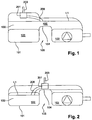
- FIGS 1 and 2 depict a sectional schematic view of a saddle fuel tank 100 having a tank shell 101.
- the tank shell 101 comprises a primary compartment 102, a secondary compartment 103 and a dome 400.
- the primary compartment 102 and the secondary compartment 103 are connected together in a communicating manner by means of a bridge 104.
- the bridge provides an exterior concavity 105 which is intended to provide accommodation for drive and/or exhaust components of the vehicle to pass freely underneath.
- a valve 200 is disposed within the fuel tank 100.
- the valve 200 is positioned at the centre of the tank ( Figure 2 ), such that it extends above the bridge 104.
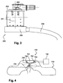
- FIG. 3 shows a valve 200 according to an embodiment of the present invention.
- the valve 200 comprises a chamber 201.
- the chamber 201 of the illustrated valve is provided with a cover 202, which may either be moulded as one part with said chamber or it may form a separate part joined to the latter by any known means (mechanical fastening with a seal; welding etc.).
- This cover 202 is advantageously connected to a venting circuit via an aperture 203.
- the aperture 203 is connected through a conduit to the inlet of a storage canister (not illustrated).
- the storage canister has an outlet conduit adapted for connection to the air inlet of an engine.
- the base 205 is fixed to the chamber by any known means (clips, screws).
- the base 205 is advantageously connected to (i.e. in communication with) the chamber 201 via an aperture.
- One extremity of the venting tube opens onto the base 205 and another extremity of the venting tube opens onto the volume of the tank.
- the open extremity corresponds to the shut-off level or the predetermined filling level L1.
- the base 205 and the venting tube 206 are made of plastic.
- valve 200 As shown in Figures 1 and 2 , the valve 200 according to a preferred embodiment of the present invention is designed to respond by taking a fully closed position when a fuel level in the tank 100 is equal to or higher than the predetermined filling level L1.
- the predetermined filling level L1 is lower than the physical maximum filling level of the left compartment 103, which would correspond to the level of the top of the bridge 104.
- valve 200 according to a preferred embodiment of the present invention comprises means for providing both the ROV function and the FLVV function.
- valve according to the invention further comprises means which confer on it the ability to act as a pressure liquid vapour separator.
- the valve 700 is disposed within the fuel tank 710.
- the valve 700 is positioned at the centre of the tank, such that it extends above the bridge 720.
- the valve 700 comprises a chamber 701.
- the chamber 701 of the valve is provided with a cover 702.
- This cover 702 is advantageously connected to a venting circuit via an aperture 703.
- the aperture 703 is connected through a conduit to the inlet of a storage canister 730.
- valve 700 further comprises a refueling vent block 704.
- the refueling vent block 704 comprises a base 705 designed to be mounted at the bottom of the chamber 701 and a venting tube 706 in charge of monitoring a level of fuel in a compartment of the tank.
- valve 700 further comprises a semi-permeable membrane 708 mounted inside the chamber 701 such that it extends between the first 706 venting tube and the aperture 703.
- membrane 708 is configured such that:
- the membrane 708 allows only fuel vapour to be transferred to the canister 730 so as to avoid contamination and pass through to the atmosphere.
- the valve further comprises a small bleed orifice.
- this bleed orifice is bored on the venting tube.
- the bleed orifice is used to minimize pressure spike at valve shut-off, in order to mitigate any fuel rising rapidly up the fill pipe and exiting the pipe as a result.
- This bleed orifice could be tuned to optimize refueling performance.
- the valve can comprise other bleed orifices placed at strategic locations, such as in an optional refueling vent block.
Landscapes
- Engineering & Computer Science (AREA)
- Life Sciences & Earth Sciences (AREA)
- Sustainable Development (AREA)
- Sustainable Energy (AREA)
- Chemical & Material Sciences (AREA)
- Combustion & Propulsion (AREA)
- Transportation (AREA)
- Mechanical Engineering (AREA)
- Cooling, Air Intake And Gas Exhaust, And Fuel Tank Arrangements In Propulsion Units (AREA)
Claims (12)
- Ventil (200), umfassend:- eine Kammer (201), die dazu ausgelegt ist, sich wenigstens teilweise in einen Tank (100) hinein zu erstrecken, und dazu ausgelegt ist, über eine obere Entlüftungsöffnung (203) mit einem Entlüftungskreislauf verbunden zu sein; und- einen Absperrpunkt, der einen einzigen Höchstfüllstand innerhalb des Tanks (100) definiert und sich entfernt von der Kammer (201) befindet, wobei der Absperrpunkt in Fluidverbindung mit der Kammer (201) ist,dadurch gekennzeichnet, dass
der Absperrpunkt über eine Leitung in Fluidverbindung mit der Kammer (201) ist,
wobei die Leitung ein Entlüftungsrohr (206) umfasst. - Ventil (200) nach Anspruch 1, wobei die Kammer durch Spritzgießen eines Kunststoffs gefertigt ist.
- Ventil (200) nach Anspruch 1 oder 2, wobei das Entlüftungsrohr (206) ein flexibles Rohr ist.
- Ventil (200) nach Anspruch 3, wobei das flexible Rohr an einem Nippel angebracht ist, der an dem Ventil vorgesehen ist.
- Ventil (200) nach Anspruch 4, wobei der Nippel in einem Stück mit der Kammer gefertigt ist.
- Ventil (200) nach einem der vorangehenden Ansprüche, wobei ein Ende der Leitung mit einem Merkmal versehen ist, das dazu geformt ist, ein Anschweißen an eine Innenwand des Tanks zu erleichtern.
- Ventil (200) nach einem der vorangehenden Ansprüche, wobei das Ventil wenigstens eine halbdurchlässige Membran umfasst, die derart im Inneren der Kammer angebracht ist, dass sie sich zwischen der Leitung und der oberen Entlüftungsöffnung erstreckt, wobei die halbdurchlässige Membran derart ausgeführt ist, dass:sie es Flüssigkeitsdampf innerhalb des Tanks gestattet, von der Leitung zu der oberen Entlüftungsöffnung zu strömen; undsie Flüssigkeit in dem Tank daran hindert, von der Leitung zu der oberen Entlüftungsöffnung zu strömen.
- Ventil (200) nach einem der vorangehenden Ansprüche, wobei das Ventil wenigstens eine Ablassöffnung umfasst.
- Kraftstofftank (100), der mit einem Ventil (200) nach einem der vorangehenden Ansprüche ausgestattet ist.
- Kraftstofftank (100) nach Anspruch 9, wobei der Kraftstofftank der Art nach ein Satteltank ist.
- Kraftfahrzeug, das mit einem Kraftstofftank (100) nach Anspruch 9 oder Anspruch 10 ausgestattet ist.
- Verwendung des Ventils (200) nach einem der Ansprüche 1-8 zum Entlüften eines Kraftstofftanks (100), wobei sich das Ventil (200) wenigstens teilweise in den Tank (100) hinein erstreckt und über die obere Entlüftungsöffnung (203) mit dem Entlüftungskreislauf verbunden ist, wobei sich der Absperrpunkt im Inneren des Tanks befindet.
Priority Applications (4)
| Application Number | Priority Date | Filing Date | Title |
|---|---|---|---|
| EP13176313.8A EP2823980B1 (de) | 2013-07-12 | 2013-07-12 | Ventil zum Entlüften eines Kraftstofftanks |
| CN201480039537.7A CN105555576B (zh) | 2013-07-12 | 2014-07-11 | 用于给燃料储箱通气的方法和阀门 |
| PCT/EP2014/064952 WO2015004277A1 (en) | 2013-07-12 | 2014-07-11 | Method and valve for venting a fuel tank |
| US14/903,998 US9925864B2 (en) | 2013-07-12 | 2014-07-11 | Method and valve for venting a fuel tank |
Applications Claiming Priority (1)
| Application Number | Priority Date | Filing Date | Title |
|---|---|---|---|
| EP13176313.8A EP2823980B1 (de) | 2013-07-12 | 2013-07-12 | Ventil zum Entlüften eines Kraftstofftanks |
Publications (2)
| Publication Number | Publication Date |
|---|---|
| EP2823980A1 EP2823980A1 (de) | 2015-01-14 |
| EP2823980B1 true EP2823980B1 (de) | 2016-04-20 |
Family
ID=48793926
Family Applications (1)
| Application Number | Title | Priority Date | Filing Date |
|---|---|---|---|
| EP13176313.8A Active EP2823980B1 (de) | 2013-07-12 | 2013-07-12 | Ventil zum Entlüften eines Kraftstofftanks |
Country Status (4)
| Country | Link |
|---|---|
| US (1) | US9925864B2 (de) |
| EP (1) | EP2823980B1 (de) |
| CN (1) | CN105555576B (de) |
| WO (1) | WO2015004277A1 (de) |
Families Citing this family (4)
| Publication number | Priority date | Publication date | Assignee | Title |
|---|---|---|---|---|
| DE102015221366A1 (de) * | 2015-10-31 | 2017-05-04 | Ti Automotive Technology Center Gmbh | Satteltank mit Schwappsperre |
| DE102016217437A1 (de) | 2016-09-13 | 2018-03-15 | Bayerische Motoren Werke Aktiengesellschaft | Behälter für ein gefrierbares Fluid zur Verwendung in einem Kraftfahrzeug |
| JP2018094967A (ja) * | 2016-12-08 | 2018-06-21 | 本田技研工業株式会社 | 鞍型燃料タンク |
| WO2021037393A1 (en) * | 2019-08-23 | 2021-03-04 | Eaton Intelligent Power Limited | Evaporative emissions fuel tank venting system control |
Family Cites Families (12)
| Publication number | Priority date | Publication date | Assignee | Title |
|---|---|---|---|---|
| US5313978A (en) * | 1992-08-31 | 1994-05-24 | Om Industrial Co., Ltd. | Ventilation line opening/closing means of fuel tank |
| IL128937A (en) * | 1999-03-11 | 2002-09-12 | Raval Agriculture Coop Soc Ltd | Multi-purpose valve |
| DE10227524A1 (de) * | 2002-06-20 | 2004-01-08 | Daimlerchrysler Ag | Kraftstofftankanlage |
| US6918405B2 (en) * | 2003-12-04 | 2005-07-19 | Alfmeier Corporation | Fill limit vent valve |
| JP2006029186A (ja) * | 2004-07-15 | 2006-02-02 | Hitachi Ltd | 燃料タンク用蓋体 |
| US20060213553A1 (en) * | 2005-03-22 | 2006-09-28 | Vaughn K. Mills & Kenneth M. Spink | Low profile overfill limit device with reverse flow capability |
| FR2886368B1 (fr) * | 2005-05-24 | 2009-03-20 | Inergy Automotive Systems Res | Clapet de securite pour circuit de mise a l'air d'un reservoir a liquide |
| DE102007042278B4 (de) * | 2007-09-06 | 2022-10-06 | Kautex Textron Gmbh & Co. Kg | Kraftstoffbehälter |
| US8272398B2 (en) * | 2009-03-18 | 2012-09-25 | Eaton Corporation | Liquid discriminating vent valve |
| US9050889B2 (en) * | 2009-09-18 | 2015-06-09 | Ti Automotive Technology Center Gmbh | Fuel tank support |
| JP5991991B2 (ja) * | 2011-01-21 | 2016-09-14 | イートン コーポレーションEaton Corporation | フロート弁一体型高圧用遮断弁 |
| EP2647516B1 (de) | 2012-04-03 | 2014-12-17 | Inergy Automotive Systems Research (Société Anonyme) | Verfahren und Ventil zum Entlüften eines Sattelkraftstofftanks |
-
2013
- 2013-07-12 EP EP13176313.8A patent/EP2823980B1/de active Active
-
2014
- 2014-07-11 US US14/903,998 patent/US9925864B2/en active Active
- 2014-07-11 WO PCT/EP2014/064952 patent/WO2015004277A1/en active Application Filing
- 2014-07-11 CN CN201480039537.7A patent/CN105555576B/zh active Active
Also Published As
| Publication number | Publication date |
|---|---|
| US9925864B2 (en) | 2018-03-27 |
| EP2823980A1 (de) | 2015-01-14 |
| CN105555576A (zh) | 2016-05-04 |
| WO2015004277A1 (en) | 2015-01-15 |
| US20160167508A1 (en) | 2016-06-16 |
| CN105555576B (zh) | 2018-09-04 |
Similar Documents
| Publication | Publication Date | Title |
|---|---|---|
| US8910675B2 (en) | Method and valve for the venting of a saddle fuel tank | |
| US8371326B2 (en) | Fuel vapor vent valve with dynamic pressure relief | |
| US6675779B2 (en) | Dual float valve for fuel tank vent with liquid carryover filter | |
| US6182693B1 (en) | Vapor canister and fuel tank assembly | |
| US8226123B2 (en) | Fuel tank | |
| US7631635B2 (en) | Liquid separator and vented fuel tank arrangement | |
| US7201155B2 (en) | Integral vapor storage and vent valve assembly for use with a small engine fuel tank and vapor emission system employing same | |
| EP2607135B1 (de) | Ventil für Kraftstoff-Belüftungssystem | |
| US9925864B2 (en) | Method and valve for venting a fuel tank | |
| US20120160220A1 (en) | Device for ventilating and aerating a fuel tank | |
| WO2018085325A1 (en) | Fill limit venting valve with high shut-off height | |
| US9592729B2 (en) | Fuel tank | |
| US7509949B2 (en) | Vaporized fuel processing device and vehicle with the same | |
| JP5428993B2 (ja) | 過給油防止装置 | |
| CN108556621B (zh) | 燃料箱系统 | |
| CN106907519B (zh) | 具有重量控制系统的阀门装置 | |
| JP2001138755A (ja) | 燃料タンク | |
| US9347403B2 (en) | Fuel tank | |
| JPH0814115A (ja) | 燃料過給油防止システム | |
| US20050235968A1 (en) | Fuel vapor recovery system | |
| US20220126683A1 (en) | Pressure relief assembly and a valve assembly that uses the pressure relief assembly | |
| JP2001138756A (ja) | 燃料タンク | |
| WO2010146452A1 (en) | Vapor vent valve with pressure relief function integrated to carbon canister |
Legal Events
| Date | Code | Title | Description |
|---|---|---|---|
| 17P | Request for examination filed |
Effective date: 20130712 |
|
| AK | Designated contracting states |
Kind code of ref document: A1 Designated state(s): AL AT BE BG CH CY CZ DE DK EE ES FI FR GB GR HR HU IE IS IT LI LT LU LV MC MK MT NL NO PL PT RO RS SE SI SK SM TR |
|
| AX | Request for extension of the european patent |
Extension state: BA ME |
|
| PUAI | Public reference made under article 153(3) epc to a published international application that has entered the european phase |
Free format text: ORIGINAL CODE: 0009012 |
|
| RIN1 | Information on inventor provided before grant (corrected) |
Inventor name: JOUIE, SEBASTIEN Inventor name: LACOME, PIERRE |
|
| R17P | Request for examination filed (corrected) |
Effective date: 20150701 |
|
| RBV | Designated contracting states (corrected) |
Designated state(s): AL AT BE BG CH CY CZ DE DK EE ES FI FR GB GR HR HU IE IS IT LI LT LU LV MC MK MT NL NO PL PT RO RS SE SI SK SM TR |
|
| RIC1 | Information provided on ipc code assigned before grant |
Ipc: B60K 15/035 20060101AFI20150722BHEP Ipc: B60K 15/03 20060101ALN20150722BHEP |
|
| GRAP | Despatch of communication of intention to grant a patent |
Free format text: ORIGINAL CODE: EPIDOSNIGR1 |
|
| INTG | Intention to grant announced |
Effective date: 20150911 |
|
| RIC1 | Information provided on ipc code assigned before grant |
Ipc: B60K 15/035 20060101AFI20151119BHEP Ipc: B60K 15/03 20060101ALN20151119BHEP |
|
| INTG | Intention to grant announced |
Effective date: 20151209 |
|
| RIC1 | Information provided on ipc code assigned before grant |
Ipc: B60K 15/035 20060101AFI20151201BHEP Ipc: B60K 15/03 20060101ALN20151201BHEP |
|
| GRAS | Grant fee paid |
Free format text: ORIGINAL CODE: EPIDOSNIGR3 |
|
| GRAA | (expected) grant |
Free format text: ORIGINAL CODE: 0009210 |
|
| AK | Designated contracting states |
Kind code of ref document: B1 Designated state(s): AL AT BE BG CH CY CZ DE DK EE ES FI FR GB GR HR HU IE IS IT LI LT LU LV MC MK MT NL NO PL PT RO RS SE SI SK SM TR |
|
| REG | Reference to a national code |
Ref country code: GB Ref legal event code: FG4D |
|
| REG | Reference to a national code |
Ref country code: CH Ref legal event code: EP |
|
| REG | Reference to a national code |
Ref country code: AT Ref legal event code: REF Ref document number: 792012 Country of ref document: AT Kind code of ref document: T Effective date: 20160515 |
|
| REG | Reference to a national code |
Ref country code: IE Ref legal event code: FG4D |
|
| REG | Reference to a national code |
Ref country code: DE Ref legal event code: R096 Ref document number: 602013006650 Country of ref document: DE |
|
| REG | Reference to a national code |
Ref country code: FR Ref legal event code: PLFP Year of fee payment: 4 |
|
| REG | Reference to a national code |
Ref country code: LT Ref legal event code: MG4D |
|
| REG | Reference to a national code |
Ref country code: AT Ref legal event code: MK05 Ref document number: 792012 Country of ref document: AT Kind code of ref document: T Effective date: 20160420 |
|
| REG | Reference to a national code |
Ref country code: NL Ref legal event code: MP Effective date: 20160420 |
|
| PG25 | Lapsed in a contracting state [announced via postgrant information from national office to epo] |
Ref country code: NL Free format text: LAPSE BECAUSE OF FAILURE TO SUBMIT A TRANSLATION OF THE DESCRIPTION OR TO PAY THE FEE WITHIN THE PRESCRIBED TIME-LIMIT Effective date: 20160420 Ref country code: NO Free format text: LAPSE BECAUSE OF FAILURE TO SUBMIT A TRANSLATION OF THE DESCRIPTION OR TO PAY THE FEE WITHIN THE PRESCRIBED TIME-LIMIT Effective date: 20160720 Ref country code: FI Free format text: LAPSE BECAUSE OF FAILURE TO SUBMIT A TRANSLATION OF THE DESCRIPTION OR TO PAY THE FEE WITHIN THE PRESCRIBED TIME-LIMIT Effective date: 20160420 Ref country code: PL Free format text: LAPSE BECAUSE OF FAILURE TO SUBMIT A TRANSLATION OF THE DESCRIPTION OR TO PAY THE FEE WITHIN THE PRESCRIBED TIME-LIMIT Effective date: 20160420 Ref country code: LT Free format text: LAPSE BECAUSE OF FAILURE TO SUBMIT A TRANSLATION OF THE DESCRIPTION OR TO PAY THE FEE WITHIN THE PRESCRIBED TIME-LIMIT Effective date: 20160420 |
|
| PG25 | Lapsed in a contracting state [announced via postgrant information from national office to epo] |
Ref country code: GR Free format text: LAPSE BECAUSE OF FAILURE TO SUBMIT A TRANSLATION OF THE DESCRIPTION OR TO PAY THE FEE WITHIN THE PRESCRIBED TIME-LIMIT Effective date: 20160721 Ref country code: HR Free format text: LAPSE BECAUSE OF FAILURE TO SUBMIT A TRANSLATION OF THE DESCRIPTION OR TO PAY THE FEE WITHIN THE PRESCRIBED TIME-LIMIT Effective date: 20160420 Ref country code: ES Free format text: LAPSE BECAUSE OF FAILURE TO SUBMIT A TRANSLATION OF THE DESCRIPTION OR TO PAY THE FEE WITHIN THE PRESCRIBED TIME-LIMIT Effective date: 20160420 Ref country code: RS Free format text: LAPSE BECAUSE OF FAILURE TO SUBMIT A TRANSLATION OF THE DESCRIPTION OR TO PAY THE FEE WITHIN THE PRESCRIBED TIME-LIMIT Effective date: 20160420 Ref country code: PT Free format text: LAPSE BECAUSE OF FAILURE TO SUBMIT A TRANSLATION OF THE DESCRIPTION OR TO PAY THE FEE WITHIN THE PRESCRIBED TIME-LIMIT Effective date: 20160822 Ref country code: AT Free format text: LAPSE BECAUSE OF FAILURE TO SUBMIT A TRANSLATION OF THE DESCRIPTION OR TO PAY THE FEE WITHIN THE PRESCRIBED TIME-LIMIT Effective date: 20160420 Ref country code: LV Free format text: LAPSE BECAUSE OF FAILURE TO SUBMIT A TRANSLATION OF THE DESCRIPTION OR TO PAY THE FEE WITHIN THE PRESCRIBED TIME-LIMIT Effective date: 20160420 Ref country code: SE Free format text: LAPSE BECAUSE OF FAILURE TO SUBMIT A TRANSLATION OF THE DESCRIPTION OR TO PAY THE FEE WITHIN THE PRESCRIBED TIME-LIMIT Effective date: 20160420 |
|
| PG25 | Lapsed in a contracting state [announced via postgrant information from national office to epo] |
Ref country code: BE Free format text: LAPSE BECAUSE OF FAILURE TO SUBMIT A TRANSLATION OF THE DESCRIPTION OR TO PAY THE FEE WITHIN THE PRESCRIBED TIME-LIMIT Effective date: 20160420 Ref country code: IT Free format text: LAPSE BECAUSE OF FAILURE TO SUBMIT A TRANSLATION OF THE DESCRIPTION OR TO PAY THE FEE WITHIN THE PRESCRIBED TIME-LIMIT Effective date: 20160420 |
|
| REG | Reference to a national code |
Ref country code: DE Ref legal event code: R097 Ref document number: 602013006650 Country of ref document: DE |
|
| PG25 | Lapsed in a contracting state [announced via postgrant information from national office to epo] |
Ref country code: DK Free format text: LAPSE BECAUSE OF FAILURE TO SUBMIT A TRANSLATION OF THE DESCRIPTION OR TO PAY THE FEE WITHIN THE PRESCRIBED TIME-LIMIT Effective date: 20160420 Ref country code: EE Free format text: LAPSE BECAUSE OF FAILURE TO SUBMIT A TRANSLATION OF THE DESCRIPTION OR TO PAY THE FEE WITHIN THE PRESCRIBED TIME-LIMIT Effective date: 20160420 Ref country code: RO Free format text: LAPSE BECAUSE OF FAILURE TO SUBMIT A TRANSLATION OF THE DESCRIPTION OR TO PAY THE FEE WITHIN THE PRESCRIBED TIME-LIMIT Effective date: 20160420 Ref country code: CZ Free format text: LAPSE BECAUSE OF FAILURE TO SUBMIT A TRANSLATION OF THE DESCRIPTION OR TO PAY THE FEE WITHIN THE PRESCRIBED TIME-LIMIT Effective date: 20160420 Ref country code: SK Free format text: LAPSE BECAUSE OF FAILURE TO SUBMIT A TRANSLATION OF THE DESCRIPTION OR TO PAY THE FEE WITHIN THE PRESCRIBED TIME-LIMIT Effective date: 20160420 |
|
| PLBE | No opposition filed within time limit |
Free format text: ORIGINAL CODE: 0009261 |
|
| STAA | Information on the status of an ep patent application or granted ep patent |
Free format text: STATUS: NO OPPOSITION FILED WITHIN TIME LIMIT |
|
| PG25 | Lapsed in a contracting state [announced via postgrant information from national office to epo] |
Ref country code: SM Free format text: LAPSE BECAUSE OF FAILURE TO SUBMIT A TRANSLATION OF THE DESCRIPTION OR TO PAY THE FEE WITHIN THE PRESCRIBED TIME-LIMIT Effective date: 20160420 |
|
| REG | Reference to a national code |
Ref country code: CH Ref legal event code: PL |
|
| 26N | No opposition filed |
Effective date: 20170123 |
|
| PG25 | Lapsed in a contracting state [announced via postgrant information from national office to epo] |
Ref country code: MC Free format text: LAPSE BECAUSE OF FAILURE TO SUBMIT A TRANSLATION OF THE DESCRIPTION OR TO PAY THE FEE WITHIN THE PRESCRIBED TIME-LIMIT Effective date: 20160420 |
|
| PG25 | Lapsed in a contracting state [announced via postgrant information from national office to epo] |
Ref country code: CH Free format text: LAPSE BECAUSE OF NON-PAYMENT OF DUE FEES Effective date: 20160731 Ref country code: LI Free format text: LAPSE BECAUSE OF NON-PAYMENT OF DUE FEES Effective date: 20160731 |
|
| REG | Reference to a national code |
Ref country code: IE Ref legal event code: MM4A |
|
| PG25 | Lapsed in a contracting state [announced via postgrant information from national office to epo] |
Ref country code: SI Free format text: LAPSE BECAUSE OF FAILURE TO SUBMIT A TRANSLATION OF THE DESCRIPTION OR TO PAY THE FEE WITHIN THE PRESCRIBED TIME-LIMIT Effective date: 20160420 |
|
| REG | Reference to a national code |
Ref country code: FR Ref legal event code: PLFP Year of fee payment: 5 |
|
| PG25 | Lapsed in a contracting state [announced via postgrant information from national office to epo] |
Ref country code: IE Free format text: LAPSE BECAUSE OF NON-PAYMENT OF DUE FEES Effective date: 20160712 |
|
| PG25 | Lapsed in a contracting state [announced via postgrant information from national office to epo] |
Ref country code: LU Free format text: LAPSE BECAUSE OF NON-PAYMENT OF DUE FEES Effective date: 20160712 |
|
| GBPC | Gb: european patent ceased through non-payment of renewal fee |
Effective date: 20170712 |
|
| PG25 | Lapsed in a contracting state [announced via postgrant information from national office to epo] |
Ref country code: GB Free format text: LAPSE BECAUSE OF NON-PAYMENT OF DUE FEES Effective date: 20170712 |
|
| PG25 | Lapsed in a contracting state [announced via postgrant information from national office to epo] |
Ref country code: HU Free format text: LAPSE BECAUSE OF FAILURE TO SUBMIT A TRANSLATION OF THE DESCRIPTION OR TO PAY THE FEE WITHIN THE PRESCRIBED TIME-LIMIT; INVALID AB INITIO Effective date: 20130712 |
|
| PG25 | Lapsed in a contracting state [announced via postgrant information from national office to epo] |
Ref country code: IS Free format text: LAPSE BECAUSE OF FAILURE TO SUBMIT A TRANSLATION OF THE DESCRIPTION OR TO PAY THE FEE WITHIN THE PRESCRIBED TIME-LIMIT Effective date: 20160420 Ref country code: CY Free format text: LAPSE BECAUSE OF FAILURE TO SUBMIT A TRANSLATION OF THE DESCRIPTION OR TO PAY THE FEE WITHIN THE PRESCRIBED TIME-LIMIT Effective date: 20160420 Ref country code: MT Free format text: LAPSE BECAUSE OF NON-PAYMENT OF DUE FEES Effective date: 20160731 Ref country code: MK Free format text: LAPSE BECAUSE OF FAILURE TO SUBMIT A TRANSLATION OF THE DESCRIPTION OR TO PAY THE FEE WITHIN THE PRESCRIBED TIME-LIMIT Effective date: 20160420 |
|
| REG | Reference to a national code |
Ref country code: FR Ref legal event code: PLFP Year of fee payment: 6 |
|
| PG25 | Lapsed in a contracting state [announced via postgrant information from national office to epo] |
Ref country code: BG Free format text: LAPSE BECAUSE OF FAILURE TO SUBMIT A TRANSLATION OF THE DESCRIPTION OR TO PAY THE FEE WITHIN THE PRESCRIBED TIME-LIMIT Effective date: 20160420 |
|
| PG25 | Lapsed in a contracting state [announced via postgrant information from national office to epo] |
Ref country code: AL Free format text: LAPSE BECAUSE OF FAILURE TO SUBMIT A TRANSLATION OF THE DESCRIPTION OR TO PAY THE FEE WITHIN THE PRESCRIBED TIME-LIMIT Effective date: 20160420 Ref country code: TR Free format text: LAPSE BECAUSE OF FAILURE TO SUBMIT A TRANSLATION OF THE DESCRIPTION OR TO PAY THE FEE WITHIN THE PRESCRIBED TIME-LIMIT Effective date: 20160420 |
|
| P01 | Opt-out of the competence of the unified patent court (upc) registered |
Effective date: 20230515 |
|
| PGFP | Annual fee paid to national office [announced via postgrant information from national office to epo] |
Ref country code: DE Payment date: 20240719 Year of fee payment: 12 |
|
| PGFP | Annual fee paid to national office [announced via postgrant information from national office to epo] |
Ref country code: FR Payment date: 20240730 Year of fee payment: 12 |