EP2823193B1 - Bremseinheit für ein fahrzeug und fahrzeug mit einer derartigen bremseinheit - Google Patents
Bremseinheit für ein fahrzeug und fahrzeug mit einer derartigen bremseinheit Download PDFInfo
- Publication number
- EP2823193B1 EP2823193B1 EP13715225.2A EP13715225A EP2823193B1 EP 2823193 B1 EP2823193 B1 EP 2823193B1 EP 13715225 A EP13715225 A EP 13715225A EP 2823193 B1 EP2823193 B1 EP 2823193B1
- Authority
- EP
- European Patent Office
- Prior art keywords
- brake
- spring
- arms
- brake unit
- vehicle
- Prior art date
- Legal status (The legal status is an assumption and is not a legal conclusion. Google has not performed a legal analysis and makes no representation as to the accuracy of the status listed.)
- Active
Links
Images



Classifications
-
- F—MECHANICAL ENGINEERING; LIGHTING; HEATING; WEAPONS; BLASTING
- F16—ENGINEERING ELEMENTS AND UNITS; GENERAL MEASURES FOR PRODUCING AND MAINTAINING EFFECTIVE FUNCTIONING OF MACHINES OR INSTALLATIONS; THERMAL INSULATION IN GENERAL
- F16D—COUPLINGS FOR TRANSMITTING ROTATION; CLUTCHES; BRAKES
- F16D55/00—Brakes with substantially-radial braking surfaces pressed together in axial direction, e.g. disc brakes
- F16D55/02—Brakes with substantially-radial braking surfaces pressed together in axial direction, e.g. disc brakes with axially-movable discs or pads pressed against axially-located rotating members
- F16D55/22—Brakes with substantially-radial braking surfaces pressed together in axial direction, e.g. disc brakes with axially-movable discs or pads pressed against axially-located rotating members by clamping an axially-located rotating disc between movable braking members, e.g. movable brake discs or brake pads
- F16D55/224—Brakes with substantially-radial braking surfaces pressed together in axial direction, e.g. disc brakes with axially-movable discs or pads pressed against axially-located rotating members by clamping an axially-located rotating disc between movable braking members, e.g. movable brake discs or brake pads with a common actuating member for the braking members
- F16D55/2245—Brakes with substantially-radial braking surfaces pressed together in axial direction, e.g. disc brakes with axially-movable discs or pads pressed against axially-located rotating members by clamping an axially-located rotating disc between movable braking members, e.g. movable brake discs or brake pads with a common actuating member for the braking members in which the common actuating member acts on two levers carrying the braking members, e.g. tong-type brakes
-
- B—PERFORMING OPERATIONS; TRANSPORTING
- B61—RAILWAYS
- B61H—BRAKES OR OTHER RETARDING DEVICES SPECIALLY ADAPTED FOR RAIL VEHICLES; ARRANGEMENT OR DISPOSITION THEREOF IN RAIL VEHICLES
- B61H5/00—Applications or arrangements of brakes with substantially radial braking surfaces pressed together in axial direction, e.g. disc brakes
-
- F—MECHANICAL ENGINEERING; LIGHTING; HEATING; WEAPONS; BLASTING
- F16—ENGINEERING ELEMENTS AND UNITS; GENERAL MEASURES FOR PRODUCING AND MAINTAINING EFFECTIVE FUNCTIONING OF MACHINES OR INSTALLATIONS; THERMAL INSULATION IN GENERAL
- F16D—COUPLINGS FOR TRANSMITTING ROTATION; CLUTCHES; BRAKES
- F16D2125/00—Components of actuators
- F16D2125/18—Mechanical mechanisms
- F16D2125/58—Mechanical mechanisms transmitting linear movement
- F16D2125/64—Levers
Definitions
- the invention relates to a brake unit for a vehicle, in particular for a rail vehicle, with an application device with two brake arms, which are provided with friction linings and under the action of an actuating element for producing a frictional engagement between the friction linings and a brake disc on the brake disc can be applied, and with a Connecting part on which the application device is held, wherein the connecting part is fixedly positionable on a chassis of the vehicle.
- the invention also relates to a vehicle, in particular a rail vehicle, with a chassis on which an axle is held, on which a brake disc is rotatably mounted and on which such a brake unit is fixedly positioned, which is associated with the brake disc.
- a generic brake unit is for example from the document DE 101 35 796 C1 known. In this known brake unit, it may come to a one-sided concern of the friction linings on the brake disc in operational use. This one-sided concern of the friction linings can be caused for example by uneven wear or tolerances in the attachment of the connecting element on the chassis.
- the invention is based on the object to prevent a one-sided concern of the friction linings of the brake unit on its associated brake disc.
- each of the brake arms is associated with a spring element for opening the brake arms, which is supported with a first end to the brake arm and a second end to the connecting part or the chassis, wherein each of the brake arms for its associated spring elements forms a protective frame, within which the largest part of the spring element is received, and that at least one of the two brake arms is provided with an adjusting device for adjusting the biasing force of the spring element supported on it.
- the two independent spring elements of which at least one of the adjusting means is variable with respect to its biasing force, it is in particular even after the initial assembly in the operational use of the brake unit possible, for example in uneven wear of the friction linings and the brake disc, the clearance between the Readjustment of friction linings and the brake disk, the integrity of the spring elements and thus the stability of the set biasing force can be ensured by the special protection of the spring elements against external influences.
- the adjusting device has an adjusting screw and a threaded bore of the brake arm for engagement of the adjusting screw, wherein the brake arm associated with the first end of the spring element is supported directly on the adjusting screw.
- the brake arm forms a guide for the supported on the adjusting screw first end of the spring element, so as to ensure that the spring element does not lose its support on the adjusting screw.
- the spring element is supported with its second end directly in a support pocket formed on the connecting part.
- the two spring elements associated supporting pockets can thus be formed in a simple manufacturing manner in the original formation of the connecting part as an integral part of the connecting part.
- the two brake arms each have two at least one connecting web fixedly connected part arms, which form the protective frame.
- These fixed at least one connecting web part arms can be formed in a simple manufacturing manner in the original formation of the respective brake arm.
- each of the two spring elements can be accommodated particularly easily within the protective frame formed by the brake arms if each of the two spring elements is a torsion spring whose spring axis runs parallel to the brake disk through the associated brake arm.
- the two brake arms can be connected to form a brake caliper each by means of a connecting bolt articulated to the connecting part, wherein the spring axis of each of the torsion springs along the axis of the respective brake arm associated connecting bolt extends and thus accommodated particularly optimal in terms of the required installation space.
- the torsion spring is a wound around the connecting bolt leg spring or a torsion bar, which passes through the connecting bolt or forms the connecting bolt.
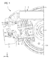
- FIG. 1 has a first inventive vehicle 1 in the form of a rail vehicle designed as a bogie chassis 2 with a bogie frame 3.
- an axle 4 is held via a primary suspension not shown here, on which two wheels are arranged rotationally fixed, of which only one 5 is shown here.
- a braking surface 6a is formed so that the wheel provided with the braking surfaces 6a forms a brake disk 6 in the form of a wheel brake disk.
- the wheel brake disc could also be a shaft brake disc - so be provided in addition to the wheel rotatably mounted on the axle brake disc.
- the brake disc 6 is associated with a first embodiment of the brake unit 7 according to the invention, which is fixedly positioned on the bogie frame 3 of the chassis.
- the brake unit could also be firmly positioned on a journal box or on a gear housing or on a motor housing of the chassis (bogie) and thus supported.
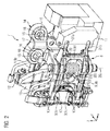
- the first embodiment of the brake unit 7 has an application device (a brake linkage) designated as a whole as 8 with two brake arms 9.
- the brake arms 9 are provided with friction linings 10 and under the action of an actuating element 11 for producing a frictional engagement between the friction linings 10 and the braking surfaces 6a of the brake disk 6 via the brake disk 6 zuspannbar.
- an actuating element 11 for example, an electropneumatic or an electro-hydraulic or an electromechanical actuator (actuator) can be used.
- the friction linings 10 are fastened to pad holders 12, which are articulated to the brake arms 9 via joints 13.
- the application device 8 is formed as a brake caliper in the brake unit shown.
- the application device could alternatively be designed as a caliper.
- the brake unit 7 further has a designated as a whole with 14 connecting part on which the application device 8 is held, wherein the connecting part 14 is fixedly positioned by means of here shown as dotted lines screw 15 on the bogie frame 3 of the chassis 2.
- the connecting part 14 here comprises a provided with two bolts 16 brake bridge 17, wherein the two bolts 16 on both sides of the brake bridge 17 mounting holes 18 for the passage of the screw 15 have.
- each of the two brake arms 9 is assigned a spring element 20 in the form of a torsion spring.
- the torsion springs 20a of the two torsion springs each extend parallel to the braking surfaces 6a of the brake disk 6 by their associated brake arms 9.
- the torsion springs are each supported with a first end 20b on the associated brake arm and with a second end 20c on the brake bridge 17 of the connecting part 14 off.
- the second end of the two spring elements could also be supported on another component, which is firmly connected to the attachment of the brake unit, which is here formed by the brake frame of the chassis.
- the two second ends of the spring elements could therefore also be assigned to support points that lie directly in the bogie.
- each of the two brake arms 9 is provided with an adjusting device 21 for adjusting the biasing force of the torsion spring supported on it.
- the adjustment of the pretensioning forces of the torsion springs offers the possibility of unilateral concern during operation the friction partner to be able to react quickly and easily.
- a relative displacement of the attachment (suspension) of the brake unit 7 in the transverse direction y relative to the braking surfaces 6a of the brake disc compensated and thus the brake unit 7 are centered relative to its suspension and relative to the brake disc 6.
- the adjusting means 21 each comprise an adjusting screw 22 (also referred to as “adjusting screw” or “stop screw”) and a threaded bore 23 of the associated brake arm 9 for engaging the adjusting screw 22nd
- the brake arm 9 associated with the first end 20b of the torsion spring is in each case supported directly on the side facing away from the head free end 22a of the adjusting screw 22.
- the adjustment means 21 asymmetries or dimensional tolerances can be easily and quickly compensated in the operational use of the brake unit 7.
- This guide slot serves as a guide 24 for the designed as a lever-like leg first end 20b of the brake arm 9 associated torsion spring.
- the two brake arms 9 are each formed of two partial arms 9a, 9b, which are firmly connected here via two connecting webs 9c, 9d.
- the connecting webs 9c, 9d extend transversely to the partial arms 9a, 9b, so that the spring axes 20a of the torsion springs extend parallel to the connecting webs 9c, 9d.
- Each of the brake arms 9 thus forms for the associated with him the spring elements 20 a protective frame, within which the largest part of the spring element 20 is received.
- the connecting webs 9c, 9d extending in the vertical direction z of the rail vehicle 1 protect the spring elements 20, in particular against the action of x in the longitudinal direction x acting pollutants.
- the partial arms 9a, 9b protect the spring elements 20 in particular from the action in the vertical direction z acting pollutants.
- the two brake arms 9 of the application device 8 are each connected by means of a connecting pin 26 articulated to the brake bridge 17 of the connecting part 14.
- the spring axes 20a of the torsion springs extend along the axis of the respective brake arm 9 associated connecting pin 26th
- First lever arms of the two partial arms 9a, 9b of one of the brake levers 9 are pivotally connected to receptacles 27a, 27b of the actuating element 11.
- First lever arms of the two partial arms 9a, 9b of the other brake lever 9 are pivotally connected to receptacles 28a, 28b of the actuating element 11.
- the receptacles 27a, 27b, 28a, 28b are driven apart and thus the first lever arms spread apart.
- On second lever arms of the two arms 9a, 9b of the brake lever 9 are provided with the friction linings pad holders are hinged, which are spanned in the spreading apart of the first lever arms on the brake disc.
- the spring element 20 is a torsion spring in the form of a wound around the connecting pin 26 leg spring.
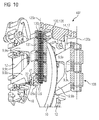
- FIGS. 9 and 10 show a second embodiment of the brake unit 107 according to the invention.
- the parts of the second embodiment which are substantially similar to those of the first embodiment, provided with the same reference numerals.
- a spring element 120 is provided, which is designed as a torsion spring in the form of a torsion bar spring.
- the torsion bar spring at the same time forms the connecting bolt 126.
- the torsion bar spring has a rod 131 provided with fixed grips 129, 130 at its ends.
- a first 129 of the clamps has a lever-like leg 129 a, which is supported on the adjusting screw 22.
- the second 130 of the restraints is rotatably connected to the brake bridge 17 of the connecting element 14.
- spring elements 20 designed as torsion springs; 120, other spring elements, for example in the form of tension or compression springs could be used.
- the two embodiments of the brake unit 7 according to the invention; 107 are characterized by their particularly simple structure and ease of use with regard to the adjustment of the biasing force of their spring elements 20; 120 off. They represent cost-effective solutions to respond to the operational unilateral contacts of the friction partners can.
- the spring elements 20; 120 also another function.
- the other function is to open the brake arms when the actuator 11 initiates no actuation force for applying the application direction 8 in the application device (reset function).
Landscapes
- Engineering & Computer Science (AREA)
- Mechanical Engineering (AREA)
- General Engineering & Computer Science (AREA)
- Braking Arrangements (AREA)
Description
- Die Erfindung betrifft eine Bremseinheit für ein Fahrzeug, insbesondere für ein Schienenfahrzeug, mit einer Zuspanneinrichtung mit zwei Bremsarmen, die mit Reibbelägen versehen und unter der Einwirkung eines Betätigungselementes zur Herstellung eines Reibschlusses zwischen den Reibbelägen und einer Bremsscheibe über der Bremsscheibe zuspannbar sind, und mit einem Verbindungsteil, an dem die Zuspanneinrichtung gehalten ist, wobei das Verbindungsteil an einem Fahrwerk des Fahrzeugs fest positionierbar ist.
- Die Erfindung betrifft auch ein Fahrzeug, insbesondere ein Schienenfahrzeug, mit einem Fahrwerk, an dem eine Achse gehalten ist, auf der eine Bremsscheibe drehfest angeordnet ist und an dem eine derartige Bremseinheit fest positioniert ist, die der Bremsscheibe zugeordnet ist.
- Eine gattungsgemäße Bremseinheit ist beispielsweise aus der Druckschrift
DE 101 35 796 C1 bekannt. Bei dieser bekannten Bremseinheit kann es im Betriebseinsatz zu einem einseitigen Anliegen der Reibbeläge an der Bremsscheibe kommen. Dieses einseitige Anliegen der Reibbeläge kann beispielsweise durch ungleichmäßigen Verschleiß oder durch Toleranzen bei der Befestigung des Verbindungselementes am Fahrwerk bedingt sein. - Dokument
US 2 375 152 offenbart eine Bremseinheit nach dem Oberbegriff des Anspruchs 1. - Der Erfindung liegt die Aufgabe zu Grunde, ein einseitiges Anliegen der Reibbeläge der Bremseinheit an der ihr zugeordneten Bremsscheibe zu verhindern.
- Zur Lösung dieser Aufgabe ist bei einer Bremseinheit der oben genannten Art vorgesehen, dass zum Öffnen der Bremsarme jedem der Bremsarme jeweils ein Federelement zugeordnet ist, das sich mit einem ersten Ende an dem Bremsarm und mit einem zweiten Ende an dem Verbindungsteil oder dem Fahrwerk abstützt, wobei jeder der Bremsarme für das ihm zugeordnete der Federelemente einen Schutzrahmen bildet, innerhalb dessen der größte Teil des Federelementes aufgenommen ist, und dass zumindest einer der beiden Bremsarme mit einer Einstelleinrichtung zum Einstellen der Vorspannkraft des an ihm abgestützten Federelementes versehen ist.
- Durch die erfindungsgemäße Bremseinheit ist es in vorteilhafter Weise möglich die Bremse im gelösten Zustand aufzuspannen, so dass diese Funktion nicht im Betätigungselement 11 erfolgen muss, sowie eine einstellbare Mittenzentrierung der Bremszange zu gewährleisten.
- Durch den Einsatz der beiden voneinander unabhängigen Federelemente, von denen zumindest eines mittels der Einsstelleinrichtung hinsichtlich seiner Vorspannkraft veränderbar ist, ist es insbesondere auch noch nach der Erstmontage im Betriebseinsatz der Bremseinheit möglich, beispielsweise bei ungleichmäßigem Verschleiß der Reibbeläge und der Bremsscheibe, das Lüftspiel zwischen den Reibbelägen und der Bremsscheibe nachzujustieren, wobei durch den besonderen Schutz der Federelemente gegen äußere Einflüsse die Unversehrtheit der Federelemente und damit die Stabilität der eingestellten Vorspannkraft sicher gestellt werden kann.
- Gemäß einer technisch besonders leicht umsetzbaren Lösung ist vorgesehen, dass die Einstelleinrichtung eine Einstellschraube und eine Gewindebohrung des Bremsarmes zum Eingriff der Einstellschraube aufweist, wobei das dem Bremsarm zugeordnete erste Ende des Federelementes unmittelbar an der Einstellschraube abgestützt ist.
- Vorzugsweise bildet dabei der Bremsarm eine Führung für das an der Einstellschraube abgestützte erste Ende des Federelementes, so dass sichergestellt ist, dass das Federelement nicht seine Abstützung an der Einstellschraube verliert.
- Es wird als vorteilhaft angesehen, wenn sich das Federelement mit seinem zweiten Ende unmittelbar in einer am Verbindungsteil ausgebildeten Abstütztasche abstützt. - Die den beiden Federelementen zugeordneten Abstütztaschen können somit auf fertigungstechnisch einfache Weise bei der Urformung des Verbindungsteils als integraler Bestandteil des Verbindungsteils ausgebildet werden.
- Ferner wird es als vorteilhaft angesehen, wenn die beiden Bremsarme jeweils zwei über zumindest einen Verbindungssteg fest verbundene Teilarme aufweisen, die den Schutzrahmen bilden. Auch diese über zumindest einen Verbindungssteg fest verbundenen Teilarme können auf fertigungstechnisch einfache Weise bei der Urformung des jeweiligen Bremsarmes ausgebildet werden.
- Besonders leicht lassen sich die Federelemente innerhalb der von den Bremsarmen gebildeten Schutzrahmen unterbringen, wenn jedes der beiden Federelemente eine Torsionsfeder ist, deren Federachse parallel zu der Bremsscheibe durch den zugeordneten Bremsarm verläuft.
- Dabei können die beiden Bremsarme zur Bildung einer Bremszange jeweils mittels eines Verbindungsbolzens gelenkig mit dem Verbindungsteil verbunden sein, wobei sich die Federachse jeder der Torsionsfedern entlang der Achse des dem jeweiligen Bremsarm zugeordneten Verbindungsbolzens erstreckt und damit hinsichtlich des benötigten Bauraumes besonders optimal untergebracht ist.
- Vorzugsweise ist die Torsionsfeder eine um den Verbindungsbolzen gewundene Schenkelfeder oder eine Drehstabfeder, die den Verbindungsbolzen durchgreift oder den Verbindungsbolzen bildet.
- Zur weiteren Erläuterung der Erfindung sind in der
- Figur 1
- ein Ausschnitt eines ersten erfindungsgemäßen Schienefahrzeugs mit einer ersten Ausführungsform der erfindungsgemäßen Bremseinheit, in den
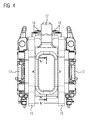
- Figuren 2 bis 7
- die erste Ausführungsform der erfindungsgemäßen Bremseinheit in verschiedenen Ansichten und Schnittdarstellungen, in der
- Figur 8
- ein Verbindungsteil der ersten Ausführungsform der erfindungsgemäßen Bremseinheit, über das diese an einem Fahrwerk des Schienenfahrzeugs fest positioniert ist, in der
- Figur 9
- einen Ausschnitt eines zweiten erfindungsgemäßen Schienefahrzeugs mit einer zweiten Ausführungsform der erfindungsgemäßen Bremseinheit und in der
- Figur 10
- eine Schnittdarstellung der zweiten Ausführungsform der erfindungsgemäßen Bremseinheit gezeigt.
- Gemäß
Figur 1 weist ein erstes erfindungsgemäßes Fahrzeug 1 in Form eines Schienefahrzeugs ein als Drehgestell ausgebildetes Fahrwerk 2 mit einem Drehgestellrahmen 3 auf. An dem Drehgestellrahmen 3 des Fahrwerkes 2 ist über eine hier nicht gezeigte Primärfederung eine Achse 4 gehalten, auf der zwei Räder drehfest angeordnet sind, von denen hier nur eins 5 gezeigt ist. An den beiden Seiten des gezeigten Rades 5 ist jeweils eine Bremsfläche 6a ausgebildet, so dass das mit den Bremsflächen 6a versehene Rad eine Bremsscheibe 6 in Form einer Radbremsscheibe bildet. Anstelle der Radbremsscheibe könnte aber auch eine Wellenbremsscheibe - also eine neben dem Rad drehfest auf der Achse angeordnete Bremsscheibe vorgesehen sein. - Der Bremsscheibe 6 ist eine erste Ausführungsform der erfindungsgemäßen Bremseinheit 7 zugeordnet, die an dem Drehgestellrahmen 3 des Fahrwerkes fest positioniert ist.
- Alternativ hierzu könnte die Bremseinheit jedoch auch an einem Achslagergehäuse oder an einem Getriebegehäuse oder an einem Motorgehäuse des Fahrwerkes (des Drehgestells) fest positioniert und damit abgestützt sein.
- Gemäß den
Figuren 2 bis 7 weist die erste Ausführungsform der erfindungsgemäßen Bremseinheit 7 eine als Ganzes mit 8 bezeichnete Zuspanneinrichtung (ein Bremsgestänge) mit zwei Bremsarmen 9 auf. Die Bremsarme 9 sind mit Reibbelägen 10 versehen und unter der Einwirkung eines Betätigungselementes 11 zur Herstellung eines Reibschlusses zwischen den Reibbelägen 10 und den Bremsflächen 6a der Bremsscheibe 6 über der Bremsscheibe 6 zuspannbar. Als Betätigungselement 11 kann beispielsweise ein elektropneumatischer oder ein elektrohydraulischer oder ein elektromechanischer Aktor (Aktuator) zum Einsatz kommen. Die Reibbeläge 10 sind an Belaghaltern 12 befestigt, die über Gelenke 13 gelenkig an den Bremsarmen 9 gehalten sind. - Die Zuspanneinrichtung 8 ist bei der gezeigten Bremseinheit als Bremszange ausgebildet. Die Zuspanneinrichtung könnte aber alternativ auch als Bremssattel ausgebildet werden.
- Die Bremseinheit 7 weist weiterhin ein als ganzes mit 14 bezeichnetes Verbindungsteil auf, an dem die Zuspanneinrichtung 8 gehalten ist, wobei das Verbindungsteil 14 mittels hier als strichpunktierte Linien dargestellter Schraubverbindungen 15 an dem Drehgestellrahmen 3 des Fahrwerkes 2 fest positioniert ist.
- Das Verbindungsteil 14 umfasst hier eine mit zwei Bolzen 16 versehene Bremsbrücke 17, wobei die beiden Bolzen 16 beidseitig der Bremsbrücke 17 Befestigungsbohrungen 18 zum Durchgriff der Schraubenverbindungen 15 aufweisen.
- Während der Erstmontage der Bremseinheit 7 am Drehgestellrahmen 3 des Fahrwerkes 2 ist eine Justierung der Position der Bremseinheit 7 über die Befestigung der Schraubenverbindungen 15 möglich, eine nachträgliche Justierung ist jedoch recht aufwändig.
- Hervorgerufen durch ungleichmäßigen Verschleiß der Reibbeläge 10 und der Bremsscheibe 6, durch Relativbewegung des Drehgestelles 2 oder auch durch Schwergängigkeit der Zuspanneinrichtung 8, kann es im Betriebseinsatz nach der Erstmontage der Bremseinheit 7 trotzdem dazu kommen kann, dass nur einer der Bremsbeläge 10 an der Bremsscheibe 6 anliegt bzw. das Lüftspiel an den beiden Reibflächen der Bremse unterschiedlich groß wird. Es kann also im Betriebseinsatz zu einem einseitigen Anliegen der Reibpartner 10, 6 kommen.
- Daher ist jedem der beiden Bremsarme 9 jeweils ein Federelement 20 in Form einer Torsionsfeder zugeordnet. Die Federachsen 20a der beiden Torsionsfedern verlaufen jeweils parallel zu den Bremsflächen 6a der Bremsscheibe 6 durch den ihnen zugeordneten der Bremsarme 9. Die Torsionsfedern stützen sich jeweils mit einem ersten Ende 20b an dem zugeordneten Bremsarm und mit einem zweiten Ende 20c an der Bremsbrücke 17 des Verbindungsteils 14 ab.
- Alternativ hierzu könnte das zweite Ende der beiden Federelemente auch an einem anderen Bauteil abgestützt sein, welches fest mit der Befestigung der Bremseinheit, die hier vom Bremsrahmen des Fahrwerkes gebildet ist, verbunden ist. Den beiden zweiten Enden der Federelemente könnten also auch Abstützpunkte zugeordnet sein, die direkt im Drehgestell liegen.
- Die Vorspannkraft mindestens eines der Federelemente 20 ist einstellbar. Bei der gezeigten Bremseinheit 7 ist jeder der beiden Bremsarme 9 jeweils mit einer Einstelleinrichtung 21 zum Einstellen der Vorspannkraft der an ihm abgestützten Torsionsfeder versehen.
- Das Einstellen der Vorspannkräfte der Torsionsfedern bietet die Möglichkeit, im Betriebseinsatz auf einseitiges Anliegen der Reibpartner schnell und einfach reagieren zu können. Es kann also beispielsweise ein Relativ-Versatz der Befestigung (der Aufhängung) der Bremseinheit 7 in Querrichtung y relativ zu den Bremsflächen 6a der Bremsscheibe ausgeglichen und damit die Bremseinheit 7 relativ zu ihrer Aufhängung und relativ zur Bremsscheibe 6 zentriert werden.
- Die Einstelleinrichtungen 21 umfassen jeweils eine Einstellschraube 22 (auch als "Verstellschraube" oder "Anschlagschraube" bezeichnet) und eine Gewindebohrung 23 des zugeordneten Bremsarmes 9 zum Eingriff der Einstellschraube 22.
- Das dem jeweiligen Bremsarm 9 zugeordnete erste Ende 20b der Torsionsfeder ist dabei jeweils unmittelbar am dem vom Kopf abgewandten freien Ende 22a der Einstellschraube 22 abgestützt. Mittels der Einstelleinrichtungen 21 können im Betriebseinsatz der Bremseinheit 7 Unsymmetrien oder Maßtoleranzen einfach und schnell ausgeglichen werden.
- Auf der zur Bremsscheibe 6 weisenden Seite der Bremsarme ist in jedem der Bremsarme ein quer zur Federachse 20a verlaufender Führungsschlitz ausgebildet. Dieser Führungsschlitz dient als Führung 24 für das als hebelartiger Schenkel ausgebildete erste Ende 20b der dem Bremsarm 9 zugeordneten Torsionsfeder.
- Wie insbesondere den
Figuren 3 ,7 und8 zu entnehmen ist, sind an der Bremsbrücke 17 des Verbindungsteils 14 zwei Abstütztaschen 25 ausgebildet. Die Torsionsfedern sind mit ihrem ebenfalls als hebelartiger Schenkel ausgebildeten zweiten Ende 20c jeweils unmittelbar in einer dieser Abstütztaschen 25 abstützt. - Die beiden Bremsarme 9 sind jeweils aus zwei Teilarmen 9a, 9b gebildet, die hier über zwei Verbindungsstege 9c, 9d fest verbunden sind. Dabei erstrecken sich die Verbindungsstege 9c, 9d quer zu den Teilarmen 9a, 9b, so dass sich die Federachsen 20a der Torsionsfedern parallel zu den Verbindungsstegen 9c, 9d erstrecken. Jeder der Bremsarme 9 bildet damit für das ihm zugeordnete der Federelemente 20 einen Schutzrahmen, innerhalb dessen der größte Teil des Federelementes 20 aufgenommen ist. So schützen die in der Hochrichtung z des Schienenfahrzeuges 1 verlaufenden Verbindungsstege 9c, 9d die Federelemente 20 insbesondere vor der Einwirkung in der Längsrichtung x wirkender Schadstoffe. Die Teilarme 9a, 9b schützen die Federelemente 20 insbesondere vor der Einwirkung in der Hochrichtung z wirkender Schadstoffe. Damit kann insbesondere die Beschädigung der Federelemente 20 durch Schadstoffe, die sich im Fahrtwind befinden oder die beim Fahren hoch gewirbelt werden, sehr wirksam unterbunden werden.
- Zur Bildung der Bremszange sind die beiden Bremsarme 9 der Zuspanneinrichtung 8 jeweils mittels eines Verbindungsbolzens 26 gelenkig mit der Bremsbrücke 17 des Verbindungsteils 14 verbunden. Die Federachsen 20a der Torsionsfedern erstrecken sich dabei entlang der Achse des dem jeweiligen Bremsarm 9 zugeordneten Verbindungsbolzens 26.
- Erste Hebelarme der beiden Teilarme 9a, 9b eines der Bremshebel 9 sind gelenkig mit Aufnahmen 27a, 27b des Betätigungselementes 11 verbunden. Erste Hebelarme der beiden Teilarme 9a, 9b des anderen Bremshebels 9 sind gelenkig mit Aufnahmen 28a, 28b des Betätigungselementes 11 verbunden. Über eine Hubbewegung der Aufnahmen 27a, 27b werden die Aufnahmen 27a, 27b, 28a, 28b auseinander getrieben und damit die ersten Hebelarme auseinander gespreizt. An zweiten Hebelarmen der beiden Teilarme 9a, 9b der Bremshebel 9 sind die mit den Reibbelägen versehenen Belaghalter angelenkt, die beim Auseinanderspreizen der ersten Hebelarme über der Bremsscheibe zugespannt werden.
- Bei der in den
Figuren 1 bis 7 gezeigten ersten Ausführungsform der erfindungsgemäßen Bremseinheit 7 ist das Federelement 20 eine Torsionsfeder in Form einer um den Verbindungsbolzen 26 gewundenen Schenkelfeder. - Die
Figuren 9 und10 zeigen eine zweite Ausführungsform der erfindungsgemäßen Bremseinheit 107. Dabei sind die Teile der zweiten Ausführungsform, die denen der ersten Ausführungsform im Wesentlichen gleichen, mit den gleichen Bezugszeichen versehen. - Bei der zweiten Ausführungsform der erfindungsgemäßen Bremseinheit 107 ist jedoch ein Federelement 120 vorgesehen, das als Torsionsfeder in Form einer Drehstabfeder ausgebildet ist. Dabei bildet die Drehstabfeder zugleich den Verbindungsbolzen 126. Die Drehstabfeder weist einen an seinen Enden mit festen Einspannungen 129, 130 versehenen Stab 131 auf. Eine erste 129 der Einspannungen weist einen hebelartigen Schenkel 129a auf, der an der Einstellschraube 22 abgestützt ist. Die zweite 130 der Einspannungen ist drehfest mit der Bremsbrücke 17 des Verbindungselementes 14 verbunden.
- Alternativ zu den als Torsionsfedern ausgebildeten Federelementen 20; 120 könnten auch andere Federelemente, beispielsweise in Form von Zug- oder Druckfedern zum Einsatz kommen.
- Die beiden Ausführungsformen der erfindungsgemäßen Bremseinheit 7; 107 zeichnen sich durch ihren besonders einfachen Aufbau und durch leichte Bedienbarkeit hinsichtlich der Einstellung der Vorspannkraft ihrer Federelemente 20; 120 aus. Sie stellen kostengünstige Lösungen dar, um auf die betrieblich auftretenden einseitigen Kontakte der Reibpartner reagieren zu können.
- Neben der Funktion, das Luftspiel der Reibbeläge 10 beidseitig der Bremsscheibe 6 gleich zu gestalten (Zentrierfunktion), erfüllen die Federelemente 20; 120 auch eine weitere Funktion. Die weitere Funktion besteht darin, die Bremsarme zu öffnen, wenn das Betätigungselement 11 keine Betätigungskraft zum Zuspannen der Zuspannrichtung 8 in die Zuspanneinrichtung einleitet (Rückstellfunktion).
Claims (10)
- Bremseinheit (7; 107) für ein Fahrzeug (1), insbesondere für ein Schienenfahrzeug,- mit einer Zuspanneinrichtung (8; 108) mit zwei Bremsarmen (9), die mit Reibbelägen (10) versehen und unter der Einwirkung eines Betätigungselementes (11) zur Herstellung eines Reibschlusses zwischen den Reibbelägen (10) und einer Bremsscheibe (6) über der Bremsscheibe (6) zuspannbar sind, und- mit einem Verbindungsteil (14), an dem die Zuspanneinrichtung (8; 108) gehalten ist,- wobei das Verbindungsteil (14) an einem Fahrwerk (2) des Fahrzeugs (1) fest positionierbar ist, wobei- zum Öffnen der Bremsarme (9) jedem der Bremsarme (9) jeweils ein Federelement (20; 120) zugeordnet ist, das sich mit einem ersten Ende (20b; 129a) an dem Bremsarm (9) und mit einem zweiten Ende (20c; 130) an dem Verbindungsteil (14) oder dem Fahrwerk (2) abstützt, wobei- zumindest einer der beiden Bremsarme (9) mit einer Einstelleinrichtung (21) zum Einstellen der Vorspannkraft des an ihm abgestützten Federelementes (20; 120) versehen ist, dadurch gekennzeichnet, dass jeder der Bremsarme (9) für das ihm zugeordnete der Federelemente (20; 120) einen Schutzrahmen bildet, innerhalb dessen der größte Teil des Federelementes (20; 120) aufgenommen ist.
- Bremseinheit (7; 107) nach Anspruch 1,
dadurch gekennzeichnet, dass
die Einstelleinrichtung (21) eine Einstellschraube (22) und eine Gewindebohrung (23) des Bremsarmes (9) zum Eingriff der Einstellschraube (22) aufweist, wobei das dem Bremsarm (9) zugeordnete erste Ende (20b; 129a) des Federelementes (20; 120) unmittelbar an der Einstellschraube (22) abgestützt ist. - Bremseinheit (7) nach Anspruch 2,
dadurch gekennzeichnet, dass
der Bremsarm (9) eine Führung (24) für das an der Einstellschraube (22) abgestützte erste Ende (20b) des Federelementes bildet. - Bremseinheit (7) nach einem der Ansprüche 1 bis 3,
dadurch gekennzeichnet, dass
sich das Federelement (20) mit seinem zweiten Ende (20c) unmittelbar in einer am Verbindungsteil (14) ausgebildeten Abstütztasche (25) abstützt. - Bremseinheit (7; 107) nach einem der Ansprüche 1 bis 4,
dadurch gekennzeichnet, dass
die beiden Bremsarme (9) jeweils zwei über zumindest einen Verbindungssteg (9c, 9d) fest verbundene Teilarme (9a, 9b) aufweisen, die den Schutzrahmen bilden. - Bremseinheit (7; 107) nach einem der Ansprüche 1 bis 5,
dadurch gekennzeichnet, dass
jedes der beiden Federelemente (20; 120) eine Torsionsfeder ist, deren Federachse (20a; 120a) parallel zu der Bremsscheibe (6) durch den zugeordneten Bremsarm (9) verläuft. - Bremseinheit (7; 107) nach Anspruch 6,
dadurch gekennzeichnet, dass- die beiden Bremsarme (9) zur Bildung einer Bremszange jeweils mittels eines Verbindungsbolzens (26; 126) gelenkig mit dem Verbindungsteil (14) verbunden sind,- wobei sich die Federachse (20a; 120a) jeder der Torsionsfedern entlang der Achse des dem jeweiligen Bremsarm (9) zugeordneten Verbindungsbolzens (26; 126) erstreckt. - Bremseinheit (7) nach Anspruch 7,
dadurch gekennzeichnet, dass
die Torsionsfeder (20) eine um den Verbindungsbolzen (26) gewundene Schenkelfeder ist. - Bremseinheit (107) nach Anspruch 7,
dadurch gekennzeichnet, dass
die Torsionsfeder (120) eine Drehstabfeder ist, wobei die Drehstabfeder den Verbindungsbolzen durchgreift oder den Verbindungsbolzen (126) bildet. - Fahrzeug (1), insbesondere Schienenfahrzeug,- mit einem Fahrwerk (2), an dem eine Achse (4) gehalten ist, auf der eine Bremsscheibe (6) drehfest angeordnet ist, und an dem eine Bremseinheit (7; 107) fest positioniert ist, die der Bremsscheibe (6) zugeordnet ist,dadurch gekennzeichnet, dass die Bremseinheit (7; 107) nach einem der Ansprüche 1 bis 9 ausgebildet ist.
Priority Applications (1)
| Application Number | Priority Date | Filing Date | Title |
|---|---|---|---|
| PL13715225T PL2823193T3 (pl) | 2012-04-30 | 2013-04-10 | Zespół hamulca do pojazdu i pojazd z takim zespołem hamulca |
Applications Claiming Priority (2)
| Application Number | Priority Date | Filing Date | Title |
|---|---|---|---|
| DE102012207194A DE102012207194A1 (de) | 2012-04-30 | 2012-04-30 | Bremseinheit für ein Fahrzeug und Fahrzeug mit einer derartigen Bremseinheit |
| PCT/EP2013/057479 WO2013164166A1 (de) | 2012-04-30 | 2013-04-10 | Bremseinheit für ein fahrzeug und fahrzeug mit einer derartigen bremseinheit |
Publications (2)
| Publication Number | Publication Date |
|---|---|
| EP2823193A1 EP2823193A1 (de) | 2015-01-14 |
| EP2823193B1 true EP2823193B1 (de) | 2016-11-30 |
Family
ID=48083184
Family Applications (1)
| Application Number | Title | Priority Date | Filing Date |
|---|---|---|---|
| EP13715225.2A Active EP2823193B1 (de) | 2012-04-30 | 2013-04-10 | Bremseinheit für ein fahrzeug und fahrzeug mit einer derartigen bremseinheit |
Country Status (7)
| Country | Link |
|---|---|
| EP (1) | EP2823193B1 (de) |
| CN (1) | CN104334905B (de) |
| DE (1) | DE102012207194A1 (de) |
| ES (1) | ES2617529T3 (de) |
| PL (1) | PL2823193T3 (de) |
| RU (1) | RU2592469C2 (de) |
| WO (1) | WO2013164166A1 (de) |
Families Citing this family (5)
| Publication number | Priority date | Publication date | Assignee | Title |
|---|---|---|---|---|
| DE102016103238A1 (de) * | 2016-02-24 | 2017-08-24 | Knorr-Bremse Systeme für Schienenfahrzeuge GmbH | Bremszangeneinheit |
| DE102017101028A1 (de) * | 2017-01-19 | 2018-07-19 | Knorr-Bremse Systeme für Schienenfahrzeuge GmbH | Bremszangeneinheit |
| ES2997158T3 (en) | 2018-10-03 | 2025-02-14 | Schweizerische Bundesbahnen Sbb | Brake system for a rail vehicle |
| US12344289B2 (en) * | 2019-07-26 | 2025-07-01 | Wabtec Hauts-De-France | Braking system comprising brake rigging, and vehicle equipped with such a braking system |
| CN112833118A (zh) * | 2019-11-25 | 2021-05-25 | 常州中车铁马科技实业有限公司 | 吊挂组件、制动夹钳单元、转向架及轨道车辆 |
Family Cites Families (13)
| Publication number | Priority date | Publication date | Assignee | Title |
|---|---|---|---|---|
| US2174402A (en) * | 1938-03-29 | 1939-09-26 | Westinghouse Air Brake Co | Disk brake device |
| US2357263A (en) * | 1942-03-19 | 1944-08-29 | Budd Wheel Co | Brake mechanism |
| US2375152A (en) * | 1943-05-08 | 1945-05-01 | Pullman Standard Car Mfg Co | Propeller shaft brake |
| US2890767A (en) * | 1955-04-25 | 1959-06-16 | American Steel Foundries | Rotor brake |
| US2855074A (en) * | 1957-01-14 | 1958-10-07 | American Steel Foundries | Rotor brake actuating mechanism |
| AT405166B (de) * | 1996-12-19 | 1999-06-25 | Siemens Sgp Verkehrstech Gmbh | Drehgestell-fahrwerk für ein schienenfahrzeug |
| DE10135796C1 (de) | 2001-07-23 | 2003-01-23 | Knorr Bremse Systeme | Bremsbackenabstützvorrichtung |
| JP4225134B2 (ja) * | 2003-06-25 | 2009-02-18 | トヨタ自動車株式会社 | 車両用懸架装置 |
| SE531450C2 (sv) * | 2006-04-07 | 2009-04-07 | Faiveley Transport Nordic Ab | Skivbromscaliper |
| DE102007032966B4 (de) * | 2007-07-16 | 2009-11-12 | Knorr-Bremse Systeme für Schienenfahrzeuge GmbH | Lagerungsanordnung für Exzenterwellen |
| RU2390449C2 (ru) * | 2008-01-09 | 2010-05-27 | Открытое акционерное общество "Транспневматика" | Дисковый тормоз транспортного средства подвижного состава железных дорог |
| CN201574061U (zh) * | 2009-07-22 | 2010-09-08 | 普世科工业制动器(北京)有限公司 | 石油钻机液压盘式刹车装置 |
| DE102011014273B4 (de) * | 2011-03-17 | 2014-04-03 | Knorr-Bremse Systeme für Schienenfahrzeuge GmbH | Bremseinrichtung eines Schienenfahrzeugs mit in Neutralposition federbelasteter Bremszangeneinheit |
-
2012
- 2012-04-30 DE DE102012207194A patent/DE102012207194A1/de not_active Withdrawn
-
2013
- 2013-04-10 WO PCT/EP2013/057479 patent/WO2013164166A1/de not_active Ceased
- 2013-04-10 CN CN201380027950.7A patent/CN104334905B/zh active Active
- 2013-04-10 EP EP13715225.2A patent/EP2823193B1/de active Active
- 2013-04-10 PL PL13715225T patent/PL2823193T3/pl unknown
- 2013-04-10 RU RU2014147313/11A patent/RU2592469C2/ru not_active IP Right Cessation
- 2013-04-10 ES ES13715225.2T patent/ES2617529T3/es active Active
Also Published As
| Publication number | Publication date |
|---|---|
| DE102012207194A1 (de) | 2013-10-31 |
| RU2014147313A (ru) | 2016-06-20 |
| WO2013164166A1 (de) | 2013-11-07 |
| RU2592469C2 (ru) | 2016-07-20 |
| CN104334905A (zh) | 2015-02-04 |
| PL2823193T3 (pl) | 2017-06-30 |
| EP2823193A1 (de) | 2015-01-14 |
| ES2617529T3 (es) | 2017-06-19 |
| CN104334905B (zh) | 2016-11-02 |
Similar Documents
| Publication | Publication Date | Title |
|---|---|---|
| EP2019935B1 (de) | Scheibenbremse sowie belagträger und druckplatte für eine solche scheibenbremse | |
| DE69004651T2 (de) | Trommelbremse mit Servo-Feststellbremsen-Funktion. | |
| DE60003262T2 (de) | Bremsvorrichtung mit Bremsnachstellungsvorrichtung | |
| EP2644926B1 (de) | Scheibenbremse mit Rückstelleinrichtung und entsprechender Bremsbelag | |
| DE102017009295A1 (de) | Scheibenbremse für ein Nutzfahrzeug und Bremsbelagsatz | |
| DE69518537T2 (de) | Mechanische betätigungseinrichtung für eine trommelbremse | |
| WO2013164166A1 (de) | Bremseinheit für ein fahrzeug und fahrzeug mit einer derartigen bremseinheit | |
| EP3571424B1 (de) | Bremszangeneinheit | |
| WO2016112895A1 (de) | Scheibenbremse sowie antriebselement einer nachstelleinrichtung einer scheibenbremse | |
| DE1750026A1 (de) | Innenbackenbremse | |
| EP3829950A1 (de) | Belaghalter für eine bremsbelaghalterung eines schienenfahrzeugs und bremsbelaghalterung | |
| EP3815937B1 (de) | Anhängekupplung | |
| DE3916227A1 (de) | Scheibenbremse mit leitbolzenanordnung | |
| DE68919463T2 (de) | Bremsbackenführungselement und dieses verwendende Bremse. | |
| DE4407293C1 (de) | Bremszange für Scheibenbremsen von Schienenfahrzeugen | |
| DE4122672C2 (de) | Duo-Servo-Trommelbremse | |
| DE19735127C1 (de) | Scheibenbremse | |
| DE3031891A1 (de) | Selbsttaetige nachstellvorrichtung fuer trommelbremsen | |
| DE2141430A1 (de) | Scheibenbremse | |
| DE19714262C2 (de) | Bremse | |
| DE4024025C2 (de) | Teilbelag-Scheibenbremse | |
| DE2504394C2 (de) | Verfahren zur Einstellung eines lastabhängigen Bremskraftreglers | |
| DE2528480C2 (de) | Sicherung für eine längeneinstellbare Zugstange von Bremszangen für Scheibenbremsen | |
| DE2636047C2 (de) | Nachstellvorrichtung für die Anschläge einer Vollscheibenbremse | |
| EP3292317B1 (de) | Scheibenbremse eines nutzfahrzeugs |
Legal Events
| Date | Code | Title | Description |
|---|---|---|---|
| PUAI | Public reference made under article 153(3) epc to a published international application that has entered the european phase |
Free format text: ORIGINAL CODE: 0009012 |
|
| 17P | Request for examination filed |
Effective date: 20141010 |
|
| AK | Designated contracting states |
Kind code of ref document: A1 Designated state(s): AL AT BE BG CH CY CZ DE DK EE ES FI FR GB GR HR HU IE IS IT LI LT LU LV MC MK MT NL NO PL PT RO RS SE SI SK SM TR |
|
| AX | Request for extension of the european patent |
Extension state: BA ME |
|
| DAX | Request for extension of the european patent (deleted) | ||
| GRAP | Despatch of communication of intention to grant a patent |
Free format text: ORIGINAL CODE: EPIDOSNIGR1 |
|
| INTG | Intention to grant announced |
Effective date: 20160623 |
|
| INTG | Intention to grant announced |
Effective date: 20160628 |
|
| GRAS | Grant fee paid |
Free format text: ORIGINAL CODE: EPIDOSNIGR3 |
|
| GRAA | (expected) grant |
Free format text: ORIGINAL CODE: 0009210 |
|
| AK | Designated contracting states |
Kind code of ref document: B1 Designated state(s): AL AT BE BG CH CY CZ DE DK EE ES FI FR GB GR HR HU IE IS IT LI LT LU LV MC MK MT NL NO PL PT RO RS SE SI SK SM TR |
|
| REG | Reference to a national code |
Ref country code: CH Ref legal event code: EP Ref country code: GB Ref legal event code: FG4D Free format text: NOT ENGLISH |
|
| REG | Reference to a national code |
Ref country code: AT Ref legal event code: REF Ref document number: 850102 Country of ref document: AT Kind code of ref document: T Effective date: 20161215 |
|
| REG | Reference to a national code |
Ref country code: IE Ref legal event code: FG4D Free format text: LANGUAGE OF EP DOCUMENT: GERMAN |
|
| REG | Reference to a national code |
Ref country code: DE Ref legal event code: R096 Ref document number: 502013005559 Country of ref document: DE |
|
| REG | Reference to a national code |
Ref country code: CH Ref legal event code: NV Representative=s name: SIEMENS SCHWEIZ AG, CH |
|
| PG25 | Lapsed in a contracting state [announced via postgrant information from national office to epo] |
Ref country code: LV Free format text: LAPSE BECAUSE OF FAILURE TO SUBMIT A TRANSLATION OF THE DESCRIPTION OR TO PAY THE FEE WITHIN THE PRESCRIBED TIME-LIMIT Effective date: 20161130 |
|
| REG | Reference to a national code |
Ref country code: LT Ref legal event code: MG4D |
|
| REG | Reference to a national code |
Ref country code: NL Ref legal event code: MP Effective date: 20161130 |
|
| REG | Reference to a national code |
Ref country code: FR Ref legal event code: PLFP Year of fee payment: 5 |
|
| PG25 | Lapsed in a contracting state [announced via postgrant information from national office to epo] |
Ref country code: SE Free format text: LAPSE BECAUSE OF FAILURE TO SUBMIT A TRANSLATION OF THE DESCRIPTION OR TO PAY THE FEE WITHIN THE PRESCRIBED TIME-LIMIT Effective date: 20161130 Ref country code: GR Free format text: LAPSE BECAUSE OF FAILURE TO SUBMIT A TRANSLATION OF THE DESCRIPTION OR TO PAY THE FEE WITHIN THE PRESCRIBED TIME-LIMIT Effective date: 20170301 Ref country code: NO Free format text: LAPSE BECAUSE OF FAILURE TO SUBMIT A TRANSLATION OF THE DESCRIPTION OR TO PAY THE FEE WITHIN THE PRESCRIBED TIME-LIMIT Effective date: 20170228 Ref country code: LT Free format text: LAPSE BECAUSE OF FAILURE TO SUBMIT A TRANSLATION OF THE DESCRIPTION OR TO PAY THE FEE WITHIN THE PRESCRIBED TIME-LIMIT Effective date: 20161130 |
|
| PG25 | Lapsed in a contracting state [announced via postgrant information from national office to epo] |
Ref country code: HR Free format text: LAPSE BECAUSE OF FAILURE TO SUBMIT A TRANSLATION OF THE DESCRIPTION OR TO PAY THE FEE WITHIN THE PRESCRIBED TIME-LIMIT Effective date: 20161130 Ref country code: RS Free format text: LAPSE BECAUSE OF FAILURE TO SUBMIT A TRANSLATION OF THE DESCRIPTION OR TO PAY THE FEE WITHIN THE PRESCRIBED TIME-LIMIT Effective date: 20161130 Ref country code: PT Free format text: LAPSE BECAUSE OF FAILURE TO SUBMIT A TRANSLATION OF THE DESCRIPTION OR TO PAY THE FEE WITHIN THE PRESCRIBED TIME-LIMIT Effective date: 20170330 Ref country code: FI Free format text: LAPSE BECAUSE OF FAILURE TO SUBMIT A TRANSLATION OF THE DESCRIPTION OR TO PAY THE FEE WITHIN THE PRESCRIBED TIME-LIMIT Effective date: 20161130 |
|
| REG | Reference to a national code |
Ref country code: ES Ref legal event code: FG2A Ref document number: 2617529 Country of ref document: ES Kind code of ref document: T3 Effective date: 20170619 |
|
| PG25 | Lapsed in a contracting state [announced via postgrant information from national office to epo] |
Ref country code: NL Free format text: LAPSE BECAUSE OF FAILURE TO SUBMIT A TRANSLATION OF THE DESCRIPTION OR TO PAY THE FEE WITHIN THE PRESCRIBED TIME-LIMIT Effective date: 20161130 |
|
| PG25 | Lapsed in a contracting state [announced via postgrant information from national office to epo] |
Ref country code: EE Free format text: LAPSE BECAUSE OF FAILURE TO SUBMIT A TRANSLATION OF THE DESCRIPTION OR TO PAY THE FEE WITHIN THE PRESCRIBED TIME-LIMIT Effective date: 20161130 Ref country code: DK Free format text: LAPSE BECAUSE OF FAILURE TO SUBMIT A TRANSLATION OF THE DESCRIPTION OR TO PAY THE FEE WITHIN THE PRESCRIBED TIME-LIMIT Effective date: 20161130 Ref country code: RO Free format text: LAPSE BECAUSE OF FAILURE TO SUBMIT A TRANSLATION OF THE DESCRIPTION OR TO PAY THE FEE WITHIN THE PRESCRIBED TIME-LIMIT Effective date: 20161130 Ref country code: SK Free format text: LAPSE BECAUSE OF FAILURE TO SUBMIT A TRANSLATION OF THE DESCRIPTION OR TO PAY THE FEE WITHIN THE PRESCRIBED TIME-LIMIT Effective date: 20161130 |
|
| RAP2 | Party data changed (patent owner data changed or rights of a patent transferred) |
Owner name: SIEMENS AKTIENGESELLSCHAFT |
|
| PG25 | Lapsed in a contracting state [announced via postgrant information from national office to epo] |
Ref country code: BG Free format text: LAPSE BECAUSE OF FAILURE TO SUBMIT A TRANSLATION OF THE DESCRIPTION OR TO PAY THE FEE WITHIN THE PRESCRIBED TIME-LIMIT Effective date: 20170228 Ref country code: SM Free format text: LAPSE BECAUSE OF FAILURE TO SUBMIT A TRANSLATION OF THE DESCRIPTION OR TO PAY THE FEE WITHIN THE PRESCRIBED TIME-LIMIT Effective date: 20161130 |
|
| REG | Reference to a national code |
Ref country code: DE Ref legal event code: R097 Ref document number: 502013005559 Country of ref document: DE |
|
| REG | Reference to a national code |
Ref country code: CH Ref legal event code: PCOW Free format text: NEW ADDRESS: WERNER-VON-SIEMENS-STRASSE 1, 80333 MUENCHEN (DE) |
|
| PLBE | No opposition filed within time limit |
Free format text: ORIGINAL CODE: 0009261 |
|
| STAA | Information on the status of an ep patent application or granted ep patent |
Free format text: STATUS: NO OPPOSITION FILED WITHIN TIME LIMIT |
|
| 26N | No opposition filed |
Effective date: 20170831 |
|
| PG25 | Lapsed in a contracting state [announced via postgrant information from national office to epo] |
Ref country code: SI Free format text: LAPSE BECAUSE OF FAILURE TO SUBMIT A TRANSLATION OF THE DESCRIPTION OR TO PAY THE FEE WITHIN THE PRESCRIBED TIME-LIMIT Effective date: 20161130 |
|
| REG | Reference to a national code |
Ref country code: CH Ref legal event code: PL |
|
| GBPC | Gb: european patent ceased through non-payment of renewal fee |
Effective date: 20170410 |
|
| REG | Reference to a national code |
Ref country code: IE Ref legal event code: MM4A |
|
| PG25 | Lapsed in a contracting state [announced via postgrant information from national office to epo] |
Ref country code: MC Free format text: LAPSE BECAUSE OF FAILURE TO SUBMIT A TRANSLATION OF THE DESCRIPTION OR TO PAY THE FEE WITHIN THE PRESCRIBED TIME-LIMIT Effective date: 20161130 |
|
| PG25 | Lapsed in a contracting state [announced via postgrant information from national office to epo] |
Ref country code: LU Free format text: LAPSE BECAUSE OF NON-PAYMENT OF DUE FEES Effective date: 20170410 Ref country code: CH Free format text: LAPSE BECAUSE OF NON-PAYMENT OF DUE FEES Effective date: 20170430 Ref country code: GB Free format text: LAPSE BECAUSE OF NON-PAYMENT OF DUE FEES Effective date: 20170410 Ref country code: LI Free format text: LAPSE BECAUSE OF NON-PAYMENT OF DUE FEES Effective date: 20170430 |
|
| REG | Reference to a national code |
Ref country code: BE Ref legal event code: MM Effective date: 20170430 |
|
| REG | Reference to a national code |
Ref country code: FR Ref legal event code: PLFP Year of fee payment: 6 |
|
| PG25 | Lapsed in a contracting state [announced via postgrant information from national office to epo] |
Ref country code: IE Free format text: LAPSE BECAUSE OF NON-PAYMENT OF DUE FEES Effective date: 20170410 |
|
| PG25 | Lapsed in a contracting state [announced via postgrant information from national office to epo] |
Ref country code: BE Free format text: LAPSE BECAUSE OF NON-PAYMENT OF DUE FEES Effective date: 20170430 |
|
| PGFP | Annual fee paid to national office [announced via postgrant information from national office to epo] |
Ref country code: PL Payment date: 20180323 Year of fee payment: 6 |
|
| PGFP | Annual fee paid to national office [announced via postgrant information from national office to epo] |
Ref country code: CZ Payment date: 20180409 Year of fee payment: 6 |
|
| PG25 | Lapsed in a contracting state [announced via postgrant information from national office to epo] |
Ref country code: MT Free format text: LAPSE BECAUSE OF FAILURE TO SUBMIT A TRANSLATION OF THE DESCRIPTION OR TO PAY THE FEE WITHIN THE PRESCRIBED TIME-LIMIT Effective date: 20161130 |
|
| PGFP | Annual fee paid to national office [announced via postgrant information from national office to epo] |
Ref country code: ES Payment date: 20180724 Year of fee payment: 6 |
|
| REG | Reference to a national code |
Ref country code: DE Ref legal event code: R081 Ref document number: 502013005559 Country of ref document: DE Owner name: SIEMENS MOBILITY GMBH, DE Free format text: FORMER OWNER: SIEMENS AKTIENGESELLSCHAFT, 80333 MUENCHEN, DE |
|
| REG | Reference to a national code |
Ref country code: AT Ref legal event code: MM01 Ref document number: 850102 Country of ref document: AT Kind code of ref document: T Effective date: 20180410 |
|
| PG25 | Lapsed in a contracting state [announced via postgrant information from national office to epo] |
Ref country code: HU Free format text: LAPSE BECAUSE OF FAILURE TO SUBMIT A TRANSLATION OF THE DESCRIPTION OR TO PAY THE FEE WITHIN THE PRESCRIBED TIME-LIMIT; INVALID AB INITIO Effective date: 20130410 |
|
| PG25 | Lapsed in a contracting state [announced via postgrant information from national office to epo] |
Ref country code: CY Free format text: LAPSE BECAUSE OF FAILURE TO SUBMIT A TRANSLATION OF THE DESCRIPTION OR TO PAY THE FEE WITHIN THE PRESCRIBED TIME-LIMIT Effective date: 20161130 Ref country code: AT Free format text: LAPSE BECAUSE OF NON-PAYMENT OF DUE FEES Effective date: 20180410 |
|
| PG25 | Lapsed in a contracting state [announced via postgrant information from national office to epo] |
Ref country code: MK Free format text: LAPSE BECAUSE OF FAILURE TO SUBMIT A TRANSLATION OF THE DESCRIPTION OR TO PAY THE FEE WITHIN THE PRESCRIBED TIME-LIMIT Effective date: 20161130 |
|
| PG25 | Lapsed in a contracting state [announced via postgrant information from national office to epo] |
Ref country code: CZ Free format text: LAPSE BECAUSE OF NON-PAYMENT OF DUE FEES Effective date: 20190410 |
|
| PG25 | Lapsed in a contracting state [announced via postgrant information from national office to epo] |
Ref country code: TR Free format text: LAPSE BECAUSE OF FAILURE TO SUBMIT A TRANSLATION OF THE DESCRIPTION OR TO PAY THE FEE WITHIN THE PRESCRIBED TIME-LIMIT Effective date: 20161130 |
|
| PG25 | Lapsed in a contracting state [announced via postgrant information from national office to epo] |
Ref country code: AL Free format text: LAPSE BECAUSE OF FAILURE TO SUBMIT A TRANSLATION OF THE DESCRIPTION OR TO PAY THE FEE WITHIN THE PRESCRIBED TIME-LIMIT Effective date: 20161130 Ref country code: IS Free format text: LAPSE BECAUSE OF FAILURE TO SUBMIT A TRANSLATION OF THE DESCRIPTION OR TO PAY THE FEE WITHIN THE PRESCRIBED TIME-LIMIT Effective date: 20170330 |
|
| REG | Reference to a national code |
Ref country code: ES Ref legal event code: FD2A Effective date: 20200828 |
|
| PG25 | Lapsed in a contracting state [announced via postgrant information from national office to epo] |
Ref country code: ES Free format text: LAPSE BECAUSE OF NON-PAYMENT OF DUE FEES Effective date: 20190411 |
|
| PG25 | Lapsed in a contracting state [announced via postgrant information from national office to epo] |
Ref country code: PL Free format text: LAPSE BECAUSE OF NON-PAYMENT OF DUE FEES Effective date: 20190410 |
|
| PGFP | Annual fee paid to national office [announced via postgrant information from national office to epo] |
Ref country code: DE Payment date: 20250620 Year of fee payment: 13 |
|
| PGFP | Annual fee paid to national office [announced via postgrant information from national office to epo] |
Ref country code: IT Payment date: 20250417 Year of fee payment: 13 |
|
| PGFP | Annual fee paid to national office [announced via postgrant information from national office to epo] |
Ref country code: FR Payment date: 20250411 Year of fee payment: 13 |
|
| REG | Reference to a national code |
Ref country code: DE Ref legal event code: R081 Ref document number: 502013005559 Country of ref document: DE Owner name: SIEMENS MOBILITY GMBH, DE Free format text: FORMER OWNER: SIEMENS MOBILITY GMBH, 81739 MUENCHEN, DE |