EP2822821B1 - Hydrodynamischer retarder und verfahren zum steuern der leistungsübertragung eines solchen - Google Patents
Hydrodynamischer retarder und verfahren zum steuern der leistungsübertragung eines solchen Download PDFInfo
- Publication number
- EP2822821B1 EP2822821B1 EP13723005.8A EP13723005A EP2822821B1 EP 2822821 B1 EP2822821 B1 EP 2822821B1 EP 13723005 A EP13723005 A EP 13723005A EP 2822821 B1 EP2822821 B1 EP 2822821B1
- Authority
- EP
- European Patent Office
- Prior art keywords
- working medium
- working
- hydrodynamic retarder
- rotor
- working chamber
- Prior art date
- Legal status (The legal status is an assumption and is not a legal conclusion. Google has not performed a legal analysis and makes no representation as to the accuracy of the status listed.)
- Active
Links
- 238000000034 method Methods 0.000 title claims description 16
- 230000005540 biological transmission Effects 0.000 title claims description 8
- 238000001816 cooling Methods 0.000 claims description 52
- 238000003860 storage Methods 0.000 claims description 12
- 238000009423 ventilation Methods 0.000 claims description 5
- 230000000694 effects Effects 0.000 claims description 2
- 238000007789 sealing Methods 0.000 claims 1
- 239000012530 fluid Substances 0.000 description 76
- 230000009471 action Effects 0.000 description 5
- 239000007788 liquid Substances 0.000 description 5
- 238000005086 pumping Methods 0.000 description 5
- XLYOFNOQVPJJNP-UHFFFAOYSA-N water Substances O XLYOFNOQVPJJNP-UHFFFAOYSA-N 0.000 description 5
- 230000013011 mating Effects 0.000 description 3
- 239000012528 membrane Substances 0.000 description 3
- 230000007704 transition Effects 0.000 description 3
- 239000002826 coolant Substances 0.000 description 2
- 230000003111 delayed effect Effects 0.000 description 2
- 239000000203 mixture Substances 0.000 description 2
- 238000010079 rubber tapping Methods 0.000 description 2
- 238000011144 upstream manufacturing Methods 0.000 description 2
- 238000013022 venting Methods 0.000 description 2
- 230000004913 activation Effects 0.000 description 1
- 238000013459 approach Methods 0.000 description 1
- 230000004888 barrier function Effects 0.000 description 1
- 230000000295 complement effect Effects 0.000 description 1
- 230000007423 decrease Effects 0.000 description 1
- 230000001419 dependent effect Effects 0.000 description 1
- 238000007599 discharging Methods 0.000 description 1
- 238000006073 displacement reaction Methods 0.000 description 1
- 230000002349 favourable effect Effects 0.000 description 1
- 238000005429 filling process Methods 0.000 description 1
- 230000005484 gravity Effects 0.000 description 1
- 230000017525 heat dissipation Effects 0.000 description 1
- 238000004519 manufacturing process Methods 0.000 description 1
- 230000009467 reduction Effects 0.000 description 1
- 238000005057 refrigeration Methods 0.000 description 1
- 230000004044 response Effects 0.000 description 1
- 230000003068 static effect Effects 0.000 description 1
Images

Classifications
-
- B—PERFORMING OPERATIONS; TRANSPORTING
- B60—VEHICLES IN GENERAL
- B60T—VEHICLE BRAKE CONTROL SYSTEMS OR PARTS THEREOF; BRAKE CONTROL SYSTEMS OR PARTS THEREOF, IN GENERAL; ARRANGEMENT OF BRAKING ELEMENTS ON VEHICLES IN GENERAL; PORTABLE DEVICES FOR PREVENTING UNWANTED MOVEMENT OF VEHICLES; VEHICLE MODIFICATIONS TO FACILITATE COOLING OF BRAKES
- B60T1/00—Arrangements of braking elements, i.e. of those parts where braking effect occurs specially for vehicles
- B60T1/02—Arrangements of braking elements, i.e. of those parts where braking effect occurs specially for vehicles acting by retarding wheels
- B60T1/08—Arrangements of braking elements, i.e. of those parts where braking effect occurs specially for vehicles acting by retarding wheels using fluid or powdered medium
- B60T1/087—Arrangements of braking elements, i.e. of those parts where braking effect occurs specially for vehicles acting by retarding wheels using fluid or powdered medium in hydrodynamic, i.e. non-positive displacement, retarders
-
- B—PERFORMING OPERATIONS; TRANSPORTING
- B60—VEHICLES IN GENERAL
- B60T—VEHICLE BRAKE CONTROL SYSTEMS OR PARTS THEREOF; BRAKE CONTROL SYSTEMS OR PARTS THEREOF, IN GENERAL; ARRANGEMENT OF BRAKING ELEMENTS ON VEHICLES IN GENERAL; PORTABLE DEVICES FOR PREVENTING UNWANTED MOVEMENT OF VEHICLES; VEHICLE MODIFICATIONS TO FACILITATE COOLING OF BRAKES
- B60T10/00—Control or regulation for continuous braking making use of fluid or powdered medium, e.g. for use when descending a long slope
- B60T10/02—Control or regulation for continuous braking making use of fluid or powdered medium, e.g. for use when descending a long slope with hydrodynamic brake
-
- F—MECHANICAL ENGINEERING; LIGHTING; HEATING; WEAPONS; BLASTING
- F16—ENGINEERING ELEMENTS AND UNITS; GENERAL MEASURES FOR PRODUCING AND MAINTAINING EFFECTIVE FUNCTIONING OF MACHINES OR INSTALLATIONS; THERMAL INSULATION IN GENERAL
- F16D—COUPLINGS FOR TRANSMITTING ROTATION; CLUTCHES; BRAKES
- F16D57/00—Liquid-resistance brakes; Brakes using the internal friction of fluids or fluid-like media, e.g. powders
- F16D57/04—Liquid-resistance brakes; Brakes using the internal friction of fluids or fluid-like media, e.g. powders with blades causing a directed flow, e.g. Föttinger type
Definitions
- the present invention relates to a method for controlling the power transmission of a hydrodynamic retarder, according to the preamble of claim 1, as well as a hydrodynamic retarder, for example for buses, trucks or rail vehicles, according to the preamble of claim 10.
- a hydrodynamic retarder for example for buses, trucks or rail vehicles, according to the preamble of claim 10.
- Such a retarder and such a method are made WO 2005/025957 A known.
- Hydrodynamic retarders have a working space which can be filled with a working medium to hydrodynamically transmit torque from a driven primary paddle wheel (rotor) to a stationary secondary paddle wheel, therefore also called a stator.
- a secondary paddle wheel revolving counter to the direction of rotation of the primary paddle wheel can also be provided in order to form a mating retarder.
- torque - referred to here as the braking torque of the retarder - is transmitted from the rotor to the stator.
- the primary blade wheel is decelerated and, in particular, the rotor shaft which is designed to rotate with the primary blade wheel is delayed.
- the size of the transmitted braking torque in braking operation depends on the so-called degree of filling of the hydrodynamic retarder. In non-braking operation, however, the working space of the retarder is emptied from the working fluid.
- the setting of a certain degree of filling of the working space of a hydrodynamic retarder and thus the control of the transmitted braking torque can either by applying a control pressure to the working space supplied or supplied working fluid or by controlling the flow cross-section in an inlet or outlet of the hydrodynamic retarder by means of a control valve, in particular Proportional valve, done without applying a control pressure on the working space supplied to the working medium.
- control pressure to the working medium of the hydrodynamic retarder
- a membrane subjected to compressed air.
- the membrane separates the working medium from an air space, which is acted upon by means of a compressed air system, in particular vehicle compressed air system.
- the membrane or equivalent piston or the like is not essential.
- the control medium pressure in particular air pressure, can also be exerted directly on the working medium supply.
- the air pressure can be varied as a control pressure and thus pressed or displaced more or less working fluid from the reservoir into the hydrodynamic circuit of the working fluid in the working space.
- the present invention relates to both above-mentioned variants for setting a specific degree of filling of the working space in braking operation.
- DE 101 50 681 A1 proposes to supply in non-braking operation the working space working fluid from an additional provided in addition to the working fluid container, opposite the working space arranged arranged container.
- the residual amount of working medium in the working space during non-braking operation heats up and therefore has to be cooled in an external circuit.
- This external circuit is usually passed through a separate heat exchanger, which is provided in addition to the relatively larger heat exchanger in the external circuit for braking operation. If the comparatively small working medium volume flow of the non-braking operation would be promoted by the large heat exchanger of the braking operation, so could accumulate in the heat exchanger entrained by the working fluid from the working space air, which is both unfavorable for the heat exchanger and on the other hand when switching the retarder, the means at the transition from non-braking operation to braking operation, to an empty bubbles of the working space, after the filling process has already started, can lead.
- the publication DE 20 2005 003 329 U1 describes a retarder rotary pump assembly in which the impeller of the water pump of the vehicle refrigeration cycle is positioned axially adjacent to the rotor of the hydrodynamic retarder on a common shaft therewith so as to vent via seals by which the rotor is sealed to a housing of the retarder To capture working fluid and returned to the vehicle cooling circuit. If only with the coolant pump coolant in the cooling circuit to be circulated and thus the retarder is idle, the seals can be cooled with water from the water pump, which then flows into the working space of the retarder and the other in the vapor state in the environment on the one hand ,
- the invention is therefore based on the object to provide a hydrodynamic retarder and a method for controlling the power transmission of such, which are improved over the prior art.
- the losses in non-braking operation of the hydrodynamic retarder should be minimized even at high speeds.
- the constructive, manufacturing and control costs of such a hydrodynamic retarder should be reduced.
- the object of the invention is achieved by a method for controlling the power transmission of a hydrodynamic retarder and by such a hydrodynamic retarder according to the independent claims.
- a hydrodynamic retarder for controlling the power transmission of a hydrodynamic retarder and by such a hydrodynamic retarder according to the independent claims.
- particularly advantageous and particularly expedient embodiments of the invention are given.
- a method for controlling the power transmission of a hydrodynamic retarder comprising a revolving bladed rotor and a bladed stator or a counter rotating rotor rotating counter to the direction of rotation of the rotor, which together form a working space which can be filled via an inlet with working fluid and emptied via an outlet thereof, wherein the Working space is filled in a braking operation with working fluid and a braking torque is generated with the hydrodynamic retarder and in a non-braking operation of the working space is emptied to a predetermined residual amount and with the hydrodynamic retarder substantially no braking torque is generated comprises the following step: Im Non-braking operation is conveyed into the work space of the hydrodynamic retarder with an idling pump working medium for setting the predetermined residual amount.
- the idling pump In contrast to a suction of the working medium from the working space with a pump or to generate a negative pressure in the working space with a pump is thus specifically pumped working fluid with an idle pump in the working space, that is, the idling pump is in the flow direction of the working fluid in front of an inlet, in particular positioned directly in front of an inlet in the working space.
- the inventors have in fact recognized that the excessive increase in idling losses with increasing speed of the retarder or the rotor thereof are due to the fact that the retarder increasingly promotes working fluid of the remaining working fluid from the working space due to its pumping action, whereas the inflow of working fluid in the work space only due gravity, because the retarder does not have the expected suction.
- the non-braking operation flowing into the working space Working medium quantity (working medium volume flow or working medium mass flow) is therefore constant, which leads to a reduction of the remaining working fluid remaining in the working space when the speed increases with increased working fluid quantity (mass flow or volume flow).
- the optimum amount of residual working medium for setting a minimum loss of ventilation is independent of the speed of the retarder and, in particular, constant. The fact that according to the invention now working medium is pumped into the working space of the hydrodynamic retarder in non-braking operation, the optimal residual working medium, in particular a constant residual working medium, can be ensured.
- an idling pump is used whose outer diameter of at least one impeller thereof is smaller than the outer diameter of the working space, in particular smaller than the diameter at which the mouth of the inlet is positioned in the working space, or even smaller than the inner diameter of the working space.
- the working medium volumetric flow or mass flow supplied to the working space during non-braking operation is proportional to the rotor and / or counterrotating rotor speed (the latter when designed as a counter-rotating retarder), so that, at a comparatively low rotational speed value, the pumping with the idling pump into the working space Working medium volume flow or mass flow is lower and correspondingly higher at a relatively higher speed value.
- the idling pump is driven directly or indirectly by the rotor or the counter rotor of the retarder.
- this can be done the impeller of an idle pump by the rotor or the rotor shaft or the counter-rotating rotor or the counter rotating rotor shaft are supported.
- One embodiment provides that during braking operation, the amount of working fluid contained in the working space is varied by a more or less strong supply of a working medium supply, which is provided outside of the working space in a working fluid reservoir, with a control pressure, depending on the control pressure more or less working fluid from the working fluid supply is displaced into the working space, and that in the non-braking operation of the working fluid reservoir is fully vented by means of a vent valve.
- a control pressure depending on the control pressure more or less working fluid from the working fluid supply is displaced into the working space, and that in the non-braking operation of the working fluid reservoir is fully vented by means of a vent valve.
- the idling pump has an impeller in the form of a disc with a radially inner inlet region for working fluid and a radially outer discharge region for working fluid, wherein the working fluid by driving the impeller and by the action of centrifugal force from the inlet region to the outlet region and out of this out into the workroom is promoted.
- the working fluid may be conducted from the working fluid reservoir to the inlet region, in particular via a working medium-conducting connection provided in addition to the external working fluid circuit in which the working fluid is circulated during braking operation.
- a hydrodynamic retarder embodied according to the invention comprises a revolving bladed rotor and a bladed stator or a countercurrent revolving counter to the direction of rotation of the rotor, which together form a working space which can be filled in the braking operation via an inlet with working medium and emptied via an outlet thereof, the working space can be filled in a brake operation with working fluid to adjust a braking torque with the hydrodynamic retarder and is emptied in a non-braking operation to a certain residual amount of working fluid and provides essentially no braking torque.
- an idle pump is provided which promotes working medium in the non-braking operation in the working space.
- the volume of flow or mass flow of working medium supplied to the working space by means of the idling pump may be selected such that it is equal to the working medium volumetric flow or mass flow discharged from the working space (as a result of the pumping action of the retarder).
- This volume of working medium constantly supplied to the working space during non-braking operation or the residual amount remaining in the working space corresponds to a fraction of the working volume. This amount is also significantly lower than the amount that is necessary to adjust with the retarder just the minimum possible, adjustable by this in braking mode braking torque.
- the residual amount remaining in the working space is selected so that in non-braking operation, a response of the retarder (and thus braking) does not take place and at the same time the no-load losses are kept as low as possible.
- an external cooling circuit is preferably provided, into which the working medium discharged via the outlet is cooled in a heat exchanger, so that in this case the working space is constantly flowed through as part of the external cooling circuit. Due to this continuous replacement of the particular entire residual amount of working medium The working space is constantly circulated to and from the working space. As a result, the heat arising in the non-braking operation due to fluid friction can be removed from the remaining amount of working medium from the working space. Damage to the retarder can be effectively avoided.
- This cooling circuit in non-braking operation can use the same heat exchanger as the external working medium circuit in braking mode.
- Measures may be taken to avoid unwanted or excessive mixing of the working medium with air in the working space of the hydrodynamic retarder during non-braking operation.
- this runs the outlet for the working fluid that circulates in non-braking operation, in the radial direction of the working space.
- a so-called scoop tube can be provided, which projects in particular into a housing of the hydrodynamic retarder in the direction of the working space or projects into the working space and extends in the radial direction.
- a derivative of working fluid in non-braking operation provided, which has the extending in the radial direction of the working space and / or extending into this scoop.
- the Scoop serves as a jam point for tapping excess working fluid from the workspace.
- the scoop tube can protrude into a gap, which limit of the rotor, counter rotating rotor, stator and / or at least one of these components surrounding housing together.
- the scoop tube extends in the region of the gap between a rotating impeller and the housing.
- the scoop tube is directly connected to the inlet region or connected indirectly via at least one connecting line, which opens into the inlet region, flow-conducting with the inlet region.
- the idle pump can supportively act on the scoop tube to dissipate working fluid from the working space via the scoop tube.
- a heat exchanger for cooling the tapped over the scoop working medium can be arranged in the at least one connecting line, which connects the scoop tube indirectly with the inlet region.
- the heat exchanger preferably has a first cooling circuit for cooling the working medium tapped off via the scoop pipe and a second cooling circuit for cooling the working medium discharged via the outlet. Both cooling circuits can be fluidly separated from each other with regard to the working medium. Due to the separate cooling circuit is an air entry, which prevents tapping of the working fluid through the scoop pipe in the second cooling circuit in which flows over the outlet discharged working fluid. This avoids that the heat exchanger fills with air, whereby its cooling capacity decreases.
- the working space is preferably supplied by the idle pump pure working fluid and not, for example, an air-working medium mixture.
- the pump thus serves the pure conveying of working fluid from the working fluid reservoir to the working space.
- the working medium is accelerated from the working medium reservoir only insofar as this is necessary to promote the working medium to the working space.
- the connecting line via which the idling pump delivers working fluid from the working fluid reservoir into the working space, opens below the working fluid level, in particular the oil level, in the working medium reservoir.
- the idling pump can be designed such that it allows or provided only in non-braking operation, the inventive inflow of working fluid to the working space. In other words, this serves only to maintain a Hämdiumstromes through the working space in non-braking operation of the retarder.
- the task of the setting a degree of filling for exerting a hydrodynamic braking torque during braking operation is achieved by a separate pressurization system.
- the idling pump may preferably be the only pump provided in the external cooling circuit.
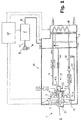
- FIG. 1 shows a hydrodynamic retarder 1 as part of a brake system of a motor vehicle with a working medium-carrying external cooling circuit, which serves to dissipate the resulting heat in the working fluid in the braking operation of the hydrodynamic retarder 1.
- the working medium is oil.
- the hydrodynamic retarder 1 could also be part of a Cooling circuit of the motor vehicle, in which case the working fluid could be water or a water mixture.
- the hydrodynamic retarder 1 comprising a rotor 2 and a stator 3, which together form a toroidal working space 4, the mouth of a first connecting line 15 from the hydrodynamic retarder 1 to a heat exchanger 11, wherein Working medium oil, also referred to as oil cooler, arranged behind this mouth fixed throttle constant cross-section, and a throttle downstream check valve, the heat exchanger 11, a mouth of a second connecting line 16 from the heat exchanger 11 to the working space 4 of the hydrodynamic retarder 1 and another throttle.
- Working medium oil also referred to as oil cooler
- the second connecting line 16 opens into an inlet 5, via which the working space 4 can be filled with working medium from the second connecting line 16 of the external cooling circuit. Via an outlet 6, in which the first connection line 15 opens, the working medium from the working space 4 is passed back into the external cooling circuit.
- the heat exchanger 11 is arranged on a working medium reservoir 7 for receiving in the working space 4 currently not required working medium.
- Working medium reservoir 7 and heat exchanger 11 could be combined into a single unit, but this need not necessarily be the case.
- the hydrodynamic retarder 1, the cooling circuit shown, the working fluid container 7 and / or the heat exchanger 11 could be combined to form such a single unit.
- the heat exchanger 11 is for cooling the working medium of the hydrodynamic retarder 1 present to a cooling circuit of the vehicle (not shown) connected to deliver the heat accumulating in the external cooling circuit of the working medium to this.
- control device 18 is a function of a to be set with the hydrodynamic retarder braking power or a braking torque to be set, for example, by means of a selector lever (not shown) selected braking stage, a corresponding overlay pressure, hereinafter referred to as control pressure calculated.
- the control pressure is adjusted by means of the pressurization system 8 in that the control device 18 more or less opens a valve in a compressed air line (not shown) of the pressurization system 8, in which compressed air from the vehicle compressed air system (also not shown) is present.
- the valve then adjusts the pressure (air pressure) in the working line 19 to act on the working medium reservoir 7 as a function of its opening cross-section.
- the latter is partly filled with air, partly with working medium.
- the working line 19 is connected in the region of a pressure medium connection 13 of the working medium container 7 here with the air side above a liquid level of the working medium to the pressurized air pressure.
- the working line 19 acts on the one hand the working medium contained in the working medium reservoir 7 with the control pressure set by the pressurizing system 8 to this more depending on the control pressure or less displace from the working fluid reservoir 7 in the external cooling circuit and thus in the working space 4 of the retarder 1.
- working medium rises into a channel which opens below the liquid level and is connected to the second connecting line 16 (downstream of the heat exchanger 11) in the direction of the working medium, in order to supply working medium from the working medium reservoir 7 via the inlet 5 to the working space 4 supply.
- the inlet 5 may be formed in the form of slots introduced in the stator 3 and / or rotor 2.
- Such slots may also be provided in addition to the inlet 5 for supplying working fluid into the working space 4 and, for example, be connected in flow-conducting manner with the second connecting line 16.
- the same also applies to the version as a mating retarder for the mating rotor (not shown).
- a scoop tube 12 may be connected, which extends from radially outside into the region of the rotor 2 and stator 3 in the working space 4 to dissipate working fluid from this in the manner of a dynamic pressure pump.
- the end of the third connecting line 17 opens at a different point in the outlet 6 than that of the first connecting line 15.
- a common outlet in the retarder 1 could be provided for each of the two connecting lines 15, 17.
- the third connection line 17 in the present case represents a side branch or parallel branch thereof. This could also be different.
- Stator 3 is here part of a housing surrounding the retarder 1 and is fixed, whereas the rotor 2 is indirectly circulated via a rotor shaft 21.
- the rotor shaft 21 is enclosed in the present case by a hollow shaft 22.
- On the hollow shaft 22 of the rotor 2 is rotatably and rotates together with this.
- the hollow shaft 22 carries on at least a portion of its inner diameter a thread, such as coarse thread and is mounted on the rotor shaft 21 axially displaceable.
- the latter has a complementary external thread, so that when filling the working chamber 4 with working fluid at the transition to braking operation due to a rotational movement of the rotor shaft 21, the hollow shaft 22 together with rotor 2 initially moved relative to the rotor shaft 21 along its longitudinal axis against a force acting as restoring force spring force of a spring is then taken by the rotor shaft 21.
- the spring serves to drive the rotor 2 again automatically, in particular when emptying the working space 4 from the stator 3.
- an idling pump 9 is provided, by means of which in non-braking operation working medium can be conveyed into the working space 4.
- the idle pump 9 in this case comprises an impeller 9.1, which is designed in the simplest case as a disc and has an inlet region 9.2 for supplying working fluid and an outlet region 9.3 for discharging working fluid.
- the inlet region 9.2 suction side
- the connecting line 23 could open in the connecting line 16, in front of or behind the throttle arranged there.
- the supply of the working medium to the inlet region 9.2 can be centric to the impeller 9.1 and here coaxial with the rotor shaft 21.
- the outlet region 9.3 also referred to as the pressure side of the idling pump 9, is arranged here in the region of the inlet 5, radially outside the impeller 9.1.
- the outlet region 9.3 thus opens directly here, ie without the interposition of further elements influencing the working medium flow, such as nozzles, valves or throttles in the region of the inlet 5.
- the idle pump 9 is not harmful if the idle pump 9 is constantly open due to the throttle used here fixed flow cross section and thus promotes working fluid in the working chamber 4 in the working chamber 4, since the funded by this working fluid flow due to the dimensions of the idle pump 9 only a fraction of the braking operation in the Working space 4 supplied volume flow corresponds. As a result, the idle pump 9 is therefore not suitable for the sole filling of the working space 4 with working fluid for adjusting a braking torque during braking operation of the retarder 1. If desired, measures can be taken regardless of the embodiment shown in Figure to prevent a promotion of working fluid with the idle pump 9 in the working space 4 during braking operation. Such a measure would be, for example, an actuatable valve (not shown), which could be arranged in the connecting line 23.
- throttle should not be designed as a fixed, but as an adjustable throttle, which would work analogously to the described valve. Throttle or valve could then be actuated via a corresponding control line (not shown) from the control pressure of the pressure medium of the pressurization system 8 automatically upon activation of the braking operation, so that they would close automatically, and the transition to non-braking operation, in which the control pressure is withdrawn, open again automatically.
- a venting valve 14 can additionally be arranged in the venting line 20, which adjusts an atmospheric pressure in the working-medium reservoir 7.
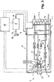
- FIG. 2 shows a further embodiment of the hydrodynamic retarder.
- corresponding elements are provided with corresponding reference numerals.
- the connecting line 17 does not open upstream of the check valve in the line 15, but downstream of the throttle in the connecting line 23. Due to the fact that the scoop 12 is connected via the connecting lines 17 and 23 indirectly to the inlet region 9.2 of the idling pump 9, the conveying effect of the working space 3 via the scoop pipe 12 tapped working medium increases. As shown, a throttle may be arranged in the connecting line 17 before the mouth into the connecting line 23.
- FIG. 3 shows a third embodiment of the hydrodynamic retarder. Again, corresponding elements are provided with corresponding reference numerals.
- the embodiment according to FIG. 3 is essentially the same as the FIG. 2
- the connecting line 17 is connected upstream of the aperture disposed therein with the heat exchanger 11.
- the heat exchanger comprises two cooling circuits 11.1, 11.2.
- Cooling circuit 11.1 is used to cool the tapped over the scoop pipe 12 working medium.
- Cooling circuit 11.2 serves to cool the discharged via the outlet 6 from the working space 3 working medium.
- Both cooling circuits 11.1, 11.2 can be fluidly separated from each other. However, this is not mandatory.
Landscapes
- Engineering & Computer Science (AREA)
- Mechanical Engineering (AREA)
- General Engineering & Computer Science (AREA)
- Physics & Mathematics (AREA)
- Fluid Mechanics (AREA)
- Transportation (AREA)
- Braking Arrangements (AREA)
- Transmission Of Braking Force In Braking Systems (AREA)
Applications Claiming Priority (2)
| Application Number | Priority Date | Filing Date | Title |
|---|---|---|---|
| DE102012004332A DE102012004332A1 (de) | 2012-03-07 | 2012-03-07 | Hydrodynamischer Retarder und Verfahren zum Steuern der Leistungsübertragung eines solchen |
| PCT/EP2013/054635 WO2013132022A2 (de) | 2012-03-07 | 2013-03-07 | Hydrodynamischer retarder und verfahren zum steuern der leistungsübertragung eines solchen |
Publications (2)
| Publication Number | Publication Date |
|---|---|
| EP2822821A2 EP2822821A2 (de) | 2015-01-14 |
| EP2822821B1 true EP2822821B1 (de) | 2016-07-20 |
Family
ID=48446245
Family Applications (1)
| Application Number | Title | Priority Date | Filing Date |
|---|---|---|---|
| EP13723005.8A Active EP2822821B1 (de) | 2012-03-07 | 2013-03-07 | Hydrodynamischer retarder und verfahren zum steuern der leistungsübertragung eines solchen |
Country Status (7)
| Country | Link |
|---|---|
| US (1) | US20140131153A1 (zh) |
| EP (1) | EP2822821B1 (zh) |
| CN (1) | CN103717463B (zh) |
| BR (1) | BR112014021956B1 (zh) |
| DE (1) | DE102012004332A1 (zh) |
| IN (1) | IN2014DN06511A (zh) |
| WO (1) | WO2013132022A2 (zh) |
Families Citing this family (15)
| Publication number | Priority date | Publication date | Assignee | Title |
|---|---|---|---|---|
| CN103671637B (zh) * | 2013-09-10 | 2017-05-03 | 深圳市特尔佳科技股份有限公司 | 一种液力缓速器的油路结构及其降低空载损耗的方法 |
| DE102013219786A1 (de) * | 2013-09-30 | 2015-04-02 | Voith Patent Gmbh | Hydrauliksystem für eine hydrodynamische Maschine |
| CN103967972B (zh) * | 2014-04-16 | 2016-04-27 | 李天维 | 一种液力阻尼器 |
| CN104595386B (zh) * | 2014-07-08 | 2015-09-30 | 武汉理工大学 | 液力缓速器用减空损装置 |
| CN104828046B (zh) * | 2015-05-22 | 2018-10-12 | 吉林大学 | 水介质缓速器的控制方法及控制装置 |
| CN105508322B (zh) * | 2015-09-17 | 2017-10-27 | 浙江大学宁波理工学院 | 泵控式液力缓速系统及其控制方法 |
| US11173882B2 (en) | 2017-04-11 | 2021-11-16 | Dana Belgium N.V. | Hydrodynamic retarder system |
| WO2018197586A1 (en) | 2017-04-26 | 2018-11-01 | Dana Belgium N.V. | Hydrodynamic retarder system and method of controlling a hydrodynamic retarder system |
| DE102018122337A1 (de) * | 2018-09-13 | 2020-03-19 | Voith Patent Gmbh | Hydrodynamischer Retarder |
| DE102019100485A1 (de) * | 2019-01-10 | 2020-07-16 | Voith Patent Gmbh | Verfahren zum Ansteuern einer hydrodynamischen Maschine und hydrodynamische Maschine |
| CN111927905A (zh) * | 2020-08-27 | 2020-11-13 | 阜新德尔汽车部件股份有限公司 | 油箱内部压力可控式液力缓速器 |
| DE102021117389A1 (de) * | 2021-07-06 | 2023-01-12 | Voith Patent Gmbh | Wärmetauscherkopplung mit einem Retardergehäuse |
| CN115199673B (zh) * | 2022-02-09 | 2023-06-30 | 富奥汽车零部件股份有限公司 | 一种液力缓速器的油路系统及其使用方法 |
| DE102022125358A1 (de) | 2022-09-30 | 2024-04-25 | Voith Patent Gmbh | Arbeitsmediumkreislauf für einen Retarder |
| DE102023105956B4 (de) | 2023-03-10 | 2024-09-19 | Voith Patent Gmbh | Hydrodynamischer Retarder mit Arbeitsmediumtank |
Family Cites Families (5)
| Publication number | Priority date | Publication date | Assignee | Title |
|---|---|---|---|---|
| DE3940825C2 (de) * | 1989-12-11 | 1995-06-29 | Voith Turbo Kg | Hydrodynamischer Retarder |
| DE10150681B4 (de) | 2001-10-17 | 2005-09-01 | Voith Turbo Gmbh & Co. Kg | Hydrodynamisches Bremssystem mit einem Retarder |
| DE10342869B4 (de) * | 2003-09-15 | 2005-07-21 | Voith Turbo Gmbh & Co. Kg | Kraftfahrzeugantrieb mit einem Wasserretarder |
| DE202005003329U1 (de) * | 2005-03-02 | 2006-07-13 | Voith Turbo Gmbh & Co. Kg | Retarder-Rotationspumpen-Baugruppe |
| DE102009016817B4 (de) * | 2009-04-09 | 2010-11-25 | Voith Patent Gmbh | Verfahren zum Einstellen eines exakten Füllstandes des Kühlmediums in einem Fahrzeugkühlkreislauf |
-
2012
- 2012-03-07 DE DE102012004332A patent/DE102012004332A1/de not_active Ceased
-
2013
- 2013-03-07 CN CN201380002110.5A patent/CN103717463B/zh active Active
- 2013-03-07 BR BR112014021956-7A patent/BR112014021956B1/pt active IP Right Grant
- 2013-03-07 EP EP13723005.8A patent/EP2822821B1/de active Active
- 2013-03-07 IN IN6511DEN2014 patent/IN2014DN06511A/en unknown
- 2013-03-07 US US14/113,564 patent/US20140131153A1/en not_active Abandoned
- 2013-03-07 WO PCT/EP2013/054635 patent/WO2013132022A2/de active Application Filing
Also Published As
| Publication number | Publication date |
|---|---|
| US20140131153A1 (en) | 2014-05-15 |
| BR112014021956B1 (pt) | 2021-07-20 |
| DE102012004332A1 (de) | 2013-09-12 |
| CN103717463A (zh) | 2014-04-09 |
| EP2822821A2 (de) | 2015-01-14 |
| WO2013132022A2 (de) | 2013-09-12 |
| IN2014DN06511A (zh) | 2015-06-12 |
| CN103717463B (zh) | 2016-06-01 |
| WO2013132022A3 (de) | 2013-10-31 |
Similar Documents
| Publication | Publication Date | Title |
|---|---|---|
| EP2822821B1 (de) | Hydrodynamischer retarder und verfahren zum steuern der leistungsübertragung eines solchen | |
| EP2006564B1 (de) | Hydrodynamische Maschine | |
| EP1565365B1 (de) | Antriebseinheit mit einem retarder | |
| EP2509831B1 (de) | Hydrodynamischer retarder und verfahren zum betreiben eines hydrodynamischen retarders | |
| EP3161320B1 (de) | Seitenkanalpumpe | |
| EP1603782B1 (de) | Kraftfahrzeugantrieb mit einem wasserretarder | |
| EP1288093B1 (de) | Hydrodynamischer Retarder | |
| DE102010026274A1 (de) | Bremsanlage und Verfahren zum Einstellen eines Bremsmomentes einer solchen | |
| EP2035266B1 (de) | Hydrodynamischer retarder | |
| DE10150681B4 (de) | Hydrodynamisches Bremssystem mit einem Retarder | |
| WO2014170113A1 (de) | Retarder mit leerlaufpumpe | |
| EP2368056B1 (de) | Hydrodynamische maschine und verfahren zur minimierung der schleppleistung einer solchen | |
| DE102011013548B4 (de) | Hydrodynamische Maschine | |
| DE102008034197B3 (de) | Hydrodynamische Maschine | |
| DE102011010555A1 (de) | Hydrodynamischer Retarder | |
| EP3849859B1 (de) | Hydrodynamischer retarder | |
| DE10150682B4 (de) | Hydrodynamisches Bremssystem mit einem Retarder | |
| DE102013213202B4 (de) | Kühlsystem mit eingebundener hydrodynamischer Maschine | |
| DE102013213201B4 (de) | Kühlsystem mit eingebundener hydrodynamischer Maschine | |
| DE102005056468B4 (de) | Hydrodynamische Maschine | |
| DE102015207850A1 (de) | Hydrodynamischer Retarder | |
| DE102014206762A1 (de) | Hydrodynamische Maschine mit optimiertem Arbeitsfluidkreislauf | |
| DE1680021A1 (de) | Hydraulische Bremsvorrichtung fuer Fahrzeuge | |
| DE102007060766A1 (de) | Hydraulische Kupplung, insbesondere hydrodynamische Kupplung |
Legal Events
| Date | Code | Title | Description |
|---|---|---|---|
| PUAI | Public reference made under article 153(3) epc to a published international application that has entered the european phase |
Free format text: ORIGINAL CODE: 0009012 |
|
| 17P | Request for examination filed |
Effective date: 20140729 |
|
| AK | Designated contracting states |
Kind code of ref document: A2 Designated state(s): AL AT BE BG CH CY CZ DE DK EE ES FI FR GB GR HR HU IE IS IT LI LT LU LV MC MK MT NL NO PL PT RO RS SE SI SK SM TR |
|
| AX | Request for extension of the european patent |
Extension state: BA ME |
|
| DAX | Request for extension of the european patent (deleted) | ||
| GRAP | Despatch of communication of intention to grant a patent |
Free format text: ORIGINAL CODE: EPIDOSNIGR1 |
|
| INTG | Intention to grant announced |
Effective date: 20160404 |
|
| GRAS | Grant fee paid |
Free format text: ORIGINAL CODE: EPIDOSNIGR3 |
|
| GRAA | (expected) grant |
Free format text: ORIGINAL CODE: 0009210 |
|
| AK | Designated contracting states |
Kind code of ref document: B1 Designated state(s): AL AT BE BG CH CY CZ DE DK EE ES FI FR GB GR HR HU IE IS IT LI LT LU LV MC MK MT NL NO PL PT RO RS SE SI SK SM TR |
|
| REG | Reference to a national code |
Ref country code: GB Ref legal event code: FG4D Free format text: NOT ENGLISH |
|
| REG | Reference to a national code |
Ref country code: CH Ref legal event code: EP |
|
| REG | Reference to a national code |
Ref country code: IE Ref legal event code: FG4D Free format text: LANGUAGE OF EP DOCUMENT: GERMAN |
|
| REG | Reference to a national code |
Ref country code: AT Ref legal event code: REF Ref document number: 813786 Country of ref document: AT Kind code of ref document: T Effective date: 20160815 |
|
| REG | Reference to a national code |
Ref country code: DE Ref legal event code: R096 Ref document number: 502013003802 Country of ref document: DE |
|
| REG | Reference to a national code |
Ref country code: LT Ref legal event code: MG4D |
|
| REG | Reference to a national code |
Ref country code: NL Ref legal event code: MP Effective date: 20160720 |
|
| PG25 | Lapsed in a contracting state [announced via postgrant information from national office to epo] |
Ref country code: FI Free format text: LAPSE BECAUSE OF FAILURE TO SUBMIT A TRANSLATION OF THE DESCRIPTION OR TO PAY THE FEE WITHIN THE PRESCRIBED TIME-LIMIT Effective date: 20160720 Ref country code: NL Free format text: LAPSE BECAUSE OF FAILURE TO SUBMIT A TRANSLATION OF THE DESCRIPTION OR TO PAY THE FEE WITHIN THE PRESCRIBED TIME-LIMIT Effective date: 20160720 Ref country code: NO Free format text: LAPSE BECAUSE OF FAILURE TO SUBMIT A TRANSLATION OF THE DESCRIPTION OR TO PAY THE FEE WITHIN THE PRESCRIBED TIME-LIMIT Effective date: 20161020 Ref country code: HR Free format text: LAPSE BECAUSE OF FAILURE TO SUBMIT A TRANSLATION OF THE DESCRIPTION OR TO PAY THE FEE WITHIN THE PRESCRIBED TIME-LIMIT Effective date: 20160720 Ref country code: LT Free format text: LAPSE BECAUSE OF FAILURE TO SUBMIT A TRANSLATION OF THE DESCRIPTION OR TO PAY THE FEE WITHIN THE PRESCRIBED TIME-LIMIT Effective date: 20160720 Ref country code: IS Free format text: LAPSE BECAUSE OF FAILURE TO SUBMIT A TRANSLATION OF THE DESCRIPTION OR TO PAY THE FEE WITHIN THE PRESCRIBED TIME-LIMIT Effective date: 20161120 Ref country code: RS Free format text: LAPSE BECAUSE OF FAILURE TO SUBMIT A TRANSLATION OF THE DESCRIPTION OR TO PAY THE FEE WITHIN THE PRESCRIBED TIME-LIMIT Effective date: 20160720 Ref country code: IT Free format text: LAPSE BECAUSE OF FAILURE TO SUBMIT A TRANSLATION OF THE DESCRIPTION OR TO PAY THE FEE WITHIN THE PRESCRIBED TIME-LIMIT Effective date: 20160720 |
|
| PG25 | Lapsed in a contracting state [announced via postgrant information from national office to epo] |
Ref country code: PL Free format text: LAPSE BECAUSE OF FAILURE TO SUBMIT A TRANSLATION OF THE DESCRIPTION OR TO PAY THE FEE WITHIN THE PRESCRIBED TIME-LIMIT Effective date: 20160720 Ref country code: PT Free format text: LAPSE BECAUSE OF FAILURE TO SUBMIT A TRANSLATION OF THE DESCRIPTION OR TO PAY THE FEE WITHIN THE PRESCRIBED TIME-LIMIT Effective date: 20161121 Ref country code: LV Free format text: LAPSE BECAUSE OF FAILURE TO SUBMIT A TRANSLATION OF THE DESCRIPTION OR TO PAY THE FEE WITHIN THE PRESCRIBED TIME-LIMIT Effective date: 20160720 Ref country code: ES Free format text: LAPSE BECAUSE OF FAILURE TO SUBMIT A TRANSLATION OF THE DESCRIPTION OR TO PAY THE FEE WITHIN THE PRESCRIBED TIME-LIMIT Effective date: 20160720 Ref country code: SE Free format text: LAPSE BECAUSE OF FAILURE TO SUBMIT A TRANSLATION OF THE DESCRIPTION OR TO PAY THE FEE WITHIN THE PRESCRIBED TIME-LIMIT Effective date: 20160720 Ref country code: GR Free format text: LAPSE BECAUSE OF FAILURE TO SUBMIT A TRANSLATION OF THE DESCRIPTION OR TO PAY THE FEE WITHIN THE PRESCRIBED TIME-LIMIT Effective date: 20161021 |
|
| REG | Reference to a national code |
Ref country code: DE Ref legal event code: R097 Ref document number: 502013003802 Country of ref document: DE |
|
| PG25 | Lapsed in a contracting state [announced via postgrant information from national office to epo] |
Ref country code: EE Free format text: LAPSE BECAUSE OF FAILURE TO SUBMIT A TRANSLATION OF THE DESCRIPTION OR TO PAY THE FEE WITHIN THE PRESCRIBED TIME-LIMIT Effective date: 20160720 Ref country code: RO Free format text: LAPSE BECAUSE OF FAILURE TO SUBMIT A TRANSLATION OF THE DESCRIPTION OR TO PAY THE FEE WITHIN THE PRESCRIBED TIME-LIMIT Effective date: 20160720 |
|
| PLBE | No opposition filed within time limit |
Free format text: ORIGINAL CODE: 0009261 |
|
| STAA | Information on the status of an ep patent application or granted ep patent |
Free format text: STATUS: NO OPPOSITION FILED WITHIN TIME LIMIT |
|
| PG25 | Lapsed in a contracting state [announced via postgrant information from national office to epo] |
Ref country code: CZ Free format text: LAPSE BECAUSE OF FAILURE TO SUBMIT A TRANSLATION OF THE DESCRIPTION OR TO PAY THE FEE WITHIN THE PRESCRIBED TIME-LIMIT Effective date: 20160720 Ref country code: DK Free format text: LAPSE BECAUSE OF FAILURE TO SUBMIT A TRANSLATION OF THE DESCRIPTION OR TO PAY THE FEE WITHIN THE PRESCRIBED TIME-LIMIT Effective date: 20160720 Ref country code: SM Free format text: LAPSE BECAUSE OF FAILURE TO SUBMIT A TRANSLATION OF THE DESCRIPTION OR TO PAY THE FEE WITHIN THE PRESCRIBED TIME-LIMIT Effective date: 20160720 Ref country code: SK Free format text: LAPSE BECAUSE OF FAILURE TO SUBMIT A TRANSLATION OF THE DESCRIPTION OR TO PAY THE FEE WITHIN THE PRESCRIBED TIME-LIMIT Effective date: 20160720 Ref country code: BG Free format text: LAPSE BECAUSE OF FAILURE TO SUBMIT A TRANSLATION OF THE DESCRIPTION OR TO PAY THE FEE WITHIN THE PRESCRIBED TIME-LIMIT Effective date: 20161020 |
|
| 26N | No opposition filed |
Effective date: 20170421 |
|
| PG25 | Lapsed in a contracting state [announced via postgrant information from national office to epo] |
Ref country code: SI Free format text: LAPSE BECAUSE OF FAILURE TO SUBMIT A TRANSLATION OF THE DESCRIPTION OR TO PAY THE FEE WITHIN THE PRESCRIBED TIME-LIMIT Effective date: 20160720 |
|
| REG | Reference to a national code |
Ref country code: CH Ref legal event code: PL |
|
| GBPC | Gb: european patent ceased through non-payment of renewal fee |
Effective date: 20170307 |
|
| PG25 | Lapsed in a contracting state [announced via postgrant information from national office to epo] |
Ref country code: MC Free format text: LAPSE BECAUSE OF FAILURE TO SUBMIT A TRANSLATION OF THE DESCRIPTION OR TO PAY THE FEE WITHIN THE PRESCRIBED TIME-LIMIT Effective date: 20160720 |
|
| REG | Reference to a national code |
Ref country code: IE Ref legal event code: MM4A |
|
| REG | Reference to a national code |
Ref country code: FR Ref legal event code: ST Effective date: 20171130 |
|
| PG25 | Lapsed in a contracting state [announced via postgrant information from national office to epo] |
Ref country code: FR Free format text: LAPSE BECAUSE OF NON-PAYMENT OF DUE FEES Effective date: 20170331 Ref country code: LU Free format text: LAPSE BECAUSE OF NON-PAYMENT OF DUE FEES Effective date: 20170307 |
|
| PG25 | Lapsed in a contracting state [announced via postgrant information from national office to epo] |
Ref country code: LI Free format text: LAPSE BECAUSE OF NON-PAYMENT OF DUE FEES Effective date: 20170331 Ref country code: IE Free format text: LAPSE BECAUSE OF NON-PAYMENT OF DUE FEES Effective date: 20170307 Ref country code: GB Free format text: LAPSE BECAUSE OF NON-PAYMENT OF DUE FEES Effective date: 20170307 Ref country code: CH Free format text: LAPSE BECAUSE OF NON-PAYMENT OF DUE FEES Effective date: 20170331 |
|
| REG | Reference to a national code |
Ref country code: BE Ref legal event code: MM Effective date: 20170331 |
|
| PG25 | Lapsed in a contracting state [announced via postgrant information from national office to epo] |
Ref country code: BE Free format text: LAPSE BECAUSE OF NON-PAYMENT OF DUE FEES Effective date: 20170331 |
|
| PG25 | Lapsed in a contracting state [announced via postgrant information from national office to epo] |
Ref country code: MT Free format text: LAPSE BECAUSE OF FAILURE TO SUBMIT A TRANSLATION OF THE DESCRIPTION OR TO PAY THE FEE WITHIN THE PRESCRIBED TIME-LIMIT Effective date: 20160720 |
|
| PG25 | Lapsed in a contracting state [announced via postgrant information from national office to epo] |
Ref country code: AL Free format text: LAPSE BECAUSE OF FAILURE TO SUBMIT A TRANSLATION OF THE DESCRIPTION OR TO PAY THE FEE WITHIN THE PRESCRIBED TIME-LIMIT Effective date: 20160720 |
|
| REG | Reference to a national code |
Ref country code: AT Ref legal event code: MM01 Ref document number: 813786 Country of ref document: AT Kind code of ref document: T Effective date: 20180307 |
|
| PG25 | Lapsed in a contracting state [announced via postgrant information from national office to epo] |
Ref country code: HU Free format text: LAPSE BECAUSE OF FAILURE TO SUBMIT A TRANSLATION OF THE DESCRIPTION OR TO PAY THE FEE WITHIN THE PRESCRIBED TIME-LIMIT; INVALID AB INITIO Effective date: 20130307 |
|
| PG25 | Lapsed in a contracting state [announced via postgrant information from national office to epo] |
Ref country code: AT Free format text: LAPSE BECAUSE OF NON-PAYMENT OF DUE FEES Effective date: 20180307 Ref country code: CY Free format text: LAPSE BECAUSE OF FAILURE TO SUBMIT A TRANSLATION OF THE DESCRIPTION OR TO PAY THE FEE WITHIN THE PRESCRIBED TIME-LIMIT Effective date: 20160720 |
|
| PG25 | Lapsed in a contracting state [announced via postgrant information from national office to epo] |
Ref country code: MK Free format text: LAPSE BECAUSE OF FAILURE TO SUBMIT A TRANSLATION OF THE DESCRIPTION OR TO PAY THE FEE WITHIN THE PRESCRIBED TIME-LIMIT Effective date: 20160720 |
|
| PG25 | Lapsed in a contracting state [announced via postgrant information from national office to epo] |
Ref country code: TR Free format text: LAPSE BECAUSE OF FAILURE TO SUBMIT A TRANSLATION OF THE DESCRIPTION OR TO PAY THE FEE WITHIN THE PRESCRIBED TIME-LIMIT Effective date: 20160720 |
|
| PGFP | Annual fee paid to national office [announced via postgrant information from national office to epo] |
Ref country code: DE Payment date: 20240320 Year of fee payment: 12 |