EP2819918B1 - Kommunikation mit einem unterwasserfahrzeug - Google Patents
Kommunikation mit einem unterwasserfahrzeug Download PDFInfo
- Publication number
- EP2819918B1 EP2819918B1 EP13711933.5A EP13711933A EP2819918B1 EP 2819918 B1 EP2819918 B1 EP 2819918B1 EP 13711933 A EP13711933 A EP 13711933A EP 2819918 B1 EP2819918 B1 EP 2819918B1
- Authority
- EP
- European Patent Office
- Prior art keywords
- vehicle
- series
- drift
- underwater
- propulsion system
- Prior art date
- Legal status (The legal status is an assumption and is not a legal conclusion. Google has not performed a legal analysis and makes no representation as to the accuracy of the status listed.)
- Not-in-force
Links
Images






Classifications
-
- H—ELECTRICITY
- H04—ELECTRIC COMMUNICATION TECHNIQUE
- H04B—TRANSMISSION
- H04B11/00—Transmission systems employing ultrasonic, sonic or infrasonic waves
-
- B—PERFORMING OPERATIONS; TRANSPORTING
- B63—SHIPS OR OTHER WATERBORNE VESSELS; RELATED EQUIPMENT
- B63G—OFFENSIVE OR DEFENSIVE ARRANGEMENTS ON VESSELS; MINE-LAYING; MINE-SWEEPING; SUBMARINES; AIRCRAFT CARRIERS
- B63G8/00—Underwater vessels, e.g. submarines; Equipment specially adapted therefor
- B63G8/08—Propulsion
-
- G—PHYSICS
- G01—MEASURING; TESTING
- G01S—RADIO DIRECTION-FINDING; RADIO NAVIGATION; DETERMINING DISTANCE OR VELOCITY BY USE OF RADIO WAVES; LOCATING OR PRESENCE-DETECTING BY USE OF THE REFLECTION OR RERADIATION OF RADIO WAVES; ANALOGOUS ARRANGEMENTS USING OTHER WAVES
- G01S19/00—Satellite radio beacon positioning systems; Determining position, velocity or attitude using signals transmitted by such systems
- G01S19/01—Satellite radio beacon positioning systems transmitting time-stamped messages, e.g. GPS [Global Positioning System], GLONASS [Global Orbiting Navigation Satellite System] or GALILEO
- G01S19/13—Receivers
- G01S19/14—Receivers specially adapted for specific applications
-
- G—PHYSICS
- G01—MEASURING; TESTING
- G01S—RADIO DIRECTION-FINDING; RADIO NAVIGATION; DETERMINING DISTANCE OR VELOCITY BY USE OF RADIO WAVES; LOCATING OR PRESENCE-DETECTING BY USE OF THE REFLECTION OR RERADIATION OF RADIO WAVES; ANALOGOUS ARRANGEMENTS USING OTHER WAVES
- G01S5/00—Position-fixing by co-ordinating two or more direction or position line determinations; Position-fixing by co-ordinating two or more distance determinations
- G01S5/0009—Transmission of position information to remote stations
-
- G—PHYSICS
- G01—MEASURING; TESTING
- G01S—RADIO DIRECTION-FINDING; RADIO NAVIGATION; DETERMINING DISTANCE OR VELOCITY BY USE OF RADIO WAVES; LOCATING OR PRESENCE-DETECTING BY USE OF THE REFLECTION OR RERADIATION OF RADIO WAVES; ANALOGOUS ARRANGEMENTS USING OTHER WAVES
- G01S5/00—Position-fixing by co-ordinating two or more direction or position line determinations; Position-fixing by co-ordinating two or more distance determinations
- G01S5/18—Position-fixing by co-ordinating two or more direction or position line determinations; Position-fixing by co-ordinating two or more distance determinations using ultrasonic, sonic or infrasonic waves
- G01S5/30—Determining absolute distances from a plurality of spaced points of known location
-
- H—ELECTRICITY
- H04—ELECTRIC COMMUNICATION TECHNIQUE
- H04B—TRANSMISSION
- H04B13/00—Transmission systems characterised by the medium used for transmission, not provided for in groups H04B3/00 - H04B11/00
- H04B13/02—Transmission systems in which the medium consists of the earth or a large mass of water thereon, e.g. earth telegraphy
-
- B—PERFORMING OPERATIONS; TRANSPORTING
- B63—SHIPS OR OTHER WATERBORNE VESSELS; RELATED EQUIPMENT
- B63G—OFFENSIVE OR DEFENSIVE ARRANGEMENTS ON VESSELS; MINE-LAYING; MINE-SWEEPING; SUBMARINES; AIRCRAFT CARRIERS
- B63G8/00—Underwater vessels, e.g. submarines; Equipment specially adapted therefor
- B63G8/001—Underwater vessels adapted for special purposes, e.g. unmanned underwater vessels; Equipment specially adapted therefor, e.g. docking stations
-
- H—ELECTRICITY
- H04—ELECTRIC COMMUNICATION TECHNIQUE
- H04L—TRANSMISSION OF DIGITAL INFORMATION, e.g. TELEGRAPHIC COMMUNICATION
- H04L25/00—Baseband systems
- H04L25/38—Synchronous or start-stop systems, e.g. for Baudot code
- H04L25/40—Transmitting circuits; Receiving circuits
- H04L25/49—Transmitting circuits; Receiving circuits using code conversion at the transmitter; using predistortion; using insertion of idle bits for obtaining a desired frequency spectrum; using three or more amplitude levels ; Baseband coding techniques specific to data transmission systems
- H04L25/4902—Pulse width modulation; Pulse position modulation
Definitions
- the present invention relates to a method of communicating with one or more underwater vehicles, a method of operating one or more underwater vehicles, and apparatus for performing such methods.
- a known method and apparatus for communicating with an underwater vehicle is described in U5119341.
- a plurality of buoys determine their positions based on Global Positioning System (GPS) navigation satellites and emit acoustic underwater data messages which contains this position.
- GPS Global Positioning System
- An underwater vehicle receives the messages and determines its position therefrom.
- Spread spectrum encoding is used to allow a single beacon carrier frequency for all buoys. Alternatively separate and locally-unique beacon carrier frequencies can be assigned to each buoy.
- US5784339 describes a communication and position determining device for use in an underwater communication and position determining system wherein the device transmits a sequence of one or more data words, wherein each data word includes a plurality of data bits transmitted in parallel as a corresponding number of concurrently transmitted signals, each of which occupies a different frequency band.
- a single one of the signals of a data word is used for position determination wherein two devices each determine the bearing to one another from the bearing of the signals received from the other and a round trip propagation time determined from the time delay in transmitting an interrogation data word, a first response data word and a second response data word.
- a first aspect of the invention provides a method of communicating with an underwater vehicle, the underwater vehicle comprising a propulsion system for propelling the vehicle through the water, the method comprising:
- a further aspect of the invention provides an underwater communication system comprising: a transmitter programmed to perform steps a) and b) above; and one or more underwater vehicles each comprising a propulsion system for propelling the vehicle through the water, and a control and processing system programmed to perform steps c), d) and e) above.
- the method may be performed with a single vehicle, or more preferably with a plurality of underwater vehicles wherein the encoded data signals are broadcast simultaneously to the underwater vehicles, typically from a single common transmitter, in the series of signal bursts.
- Data may be transmitted to the vehicle(s) by a single transmitter only.
- the encoded data signals are transmitted to the underwater vehicle in a series of signal bursts by a first transmitter at a first location, and the method further comprises:
- first and second series of signal bursts start at substantially the same time.
- the vehicle comprises an annular hull with a duct, wherein water flows through the duct and generates lift during the thrust pulses and during the drift periods.
- a further aspect of the invention provides a method of operating an underwater vehicle, the underwater vehicle comprising an annular hull with a duct; and a propulsion system for propelling the vehicle through the water, the method comprising:
- This method may be performed by a single annular vehicle or by a plurality of underwater vehicles.
- a further aspect of the invention provides an underwater vehicle comprising an annular hull with a duct; a propulsion system for propelling the vehicle through the water; and a control and processing system programmed to perform the method described in the further aspect of the invention described above.
- the annular hull comprises an outer skin defining an outer profile of the hull and an inner skin defining the duct.
- the inner and outer skins typically meet at a leading edge of the hull and at a trailing edge of the hull.
- control and processing system is housed at least partially within the hull between the inner and outer skins.
- the vehicle further comprises an antenna for receiving the signal pulses, wherein the antenna is flush with the inner and outer skins, or housed between the inner and outer skins.
- control and processing system comprises a clock which can be set to provide a clock signal which enables the control and processing system to time the drift periods such that each signal burst arrives at the underwater vehicle during a drift period and not during a thrust pulse.
- a further aspect of the invention provides a method of operating a plurality of underwater vehicles to receive a series of data sets which have been broadcast to them, each underwater vehicle comprising a propulsion system for propelling the vehicle through the water, the method comprising for each vehicle:
- a further aspect of the invention provides a plurality of underwater vehicles, each comprising a propulsion system for propelling the vehicle through the water, and a control and processing system programmed to operate the vehicle by the method described in the preceding paragraph.
- the signal bursts may comprise acoustic signal bursts, or they may comprise electromagnetic signal bursts.
- the (or each) vehicle comprises a receiver such as an acoustic or electromagnetic antenna for receiving the signal pulses.
- the propulsion systems of the vehicles may be operated substantially synchronously such that the drift periods of all of the vehicles start and finish at substantially the same time.
- the propulsion systems may be operated asynchronously such that the drift periods of at least a first one of the vehicles start and/or finish at different times to at least a second one of the vehicles.
- the drift periods may be fixed at the beginning of a mission and remain constant for that mission.
- the method may further comprise measuring a parameter for the (or each) vehicle; and varying the timing of the drift periods accordingly.
- the timing of the drift periods may be varied asynchronously such that the drift periods of at least a first one of the vehicles are varied differently to the drift periods of at least a second one of the vehicles.
- the method may further comprise estimating a time of arrival of the signal bursts at the (or each) vehicle; and varying the timing of the drift periods accordingly, wherein a delay in the estimated time of arrival causes a delay in a start and/or finish time of the drift periods.
- the time of arrival may be estimated by measuring the time of arrival of a pulse train in a previous cycle relative to a known transmission time for that pulse train.
- the method may further comprise measuring a proximity of the (or each) vehicle to other vehicles; and varying the timing of the drift periods accordingly, wherein increased proximity causes an increase in the length of the drift periods.
- the method may further comprise measuring a direction of motion of the (or each) vehicle; and varying the timing of the drift periods accordingly. For instance motion away from a transmitter of the signal bursts may cause a delay in a start and/or finish time of the drift periods.
- the method may further comprise measuring a speed of the (or each) vehicle; and varying the lengths of the drift periods accordingly. For instance an increase in speed may cause the length of the drift periods to increase.
- the average duration of the thrust pulses may be less than the average duration of the quiet periods for the (or each) vehicle - for instance less than 50% of the average duration of the quiet periods for the (or each) vehicle. In another embodiment the average duration of the thrust pulses is greater than the average duration of the quiet periods for the (or each) vehicle.
- the propulsion system may generate a small amount of thrust during the drift periods, but more preferably the (or each) propulsion system generates substantially zero thrust during the quiet periods.
- the series of signal bursts are transmitted by a transmitter with a transmit clock which is used to determine the timings of the series of signal bursts.
- the method further comprises synchronizing a receive clock on the (or each) vehicle with the transmit clock; and using the receive clock to determine the timings of the drift periods.
- Each data set may consist of a single item of data, or a plurality of items of data.
- Each data set may preferably contain the location coordinates of the transmitter of the data.
- the data may be encoded in a number of ways, but most preferably it is encoded by pulse position modulation. Thus the data may preferably be used to determine the position of the (or each) vehicle by the following process:
- FIG. 1 shows an underwater communication system.
- Three transmitter buoys 1a-c are deployed on the surface of the water.
- Each buoy has a Global Positioning System (GPS) antenna 2, a processor 3 and an acoustic antenna 4.
- GPS Global Positioning System
- the GPS antenna 2 receives GPS data signals 10 from a GPS satellite 11 and from a Differential GPS (DGPS) reference station 12 on a surface vessel 13.
- the processor 3 processes the GPS data signals 10 to determine the position of the buoy 1 in a known manner.
- DGPS Differential GPS
- FIG. 2 is a schematic diagram illustrating the method steps performed by the processors 3.
- the position of the buoy 1a-c is first determined in GPS coordinates (latitude, longitude and altitude) and stored as position data 20.
- This data 20 is then transformed at step 21 into a local coordinate system having an origin 22 (again, defined in terms of GPS coordinates) to give a grid position 23.
- This process is illustrated in Figure 3 which shows an origin 22, and a cube 24 with orthogonal X, Y and Z axes meeting at the origin. Any position within the cube can be defined by three grid coordinates x, y, z relative to the origin 22.
- the processor 3 is programmed to cause the acoustic transmitter 4 to transmit a chirp pulse position modulated acoustic pulse train 25 which encodes the xyz position of the buoy 1 as shown in Figure 4 .
- This pulse train 25 is encoded from the grid position data 23 at step 26 in accordance with reference chirp data 27 and survey grid property data 28.
- the reference chirp data 27 defines for each a buoy a start frequency F1, a finish frequency F2, and a monotonic function which defines how the chirp frequency changes from F2 to F2 with respect to time (for instance the frequency might change at a constant rate between F1 and F2).
- the survey grid property data 28 defines the size of the cube 24 in meters (for instance 4096m by 4096m by 4096m), the resolution required (for instance 0.25 m) and the maximum time between adjacent pulses in the pulse sequence (for instance 0. Is).
- the pulse train 25 shown in Figure 4 comprises four low-to-high-frequency chirps 30-33 and a single high-to-low-frequency chirp 34.
- the low-to-high-frequency chirps 30-33 have a frequency which increases at a constant rate between a first low frequency F1 at the beginning of the pulse and a second high frequency F2 at the end of the pulse.
- the low-to-high-frequency chirps 30-33 start at times to, t x , t y , and t z , respectively.
- the high-to-low-frequency chirp 34 has a frequency which decreases at a constant rate between a first high frequency at the beginning of the pulse and a low high frequency at the end of the pulse.
- the chirps 30,34 are used to signal the start of the pulse sequence.
- the chirps in the pulse train of Figure 4 have a frequency which changes at a constant rate.
- the chirps may instead have a period which changes at a constant rate.
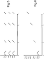
- the chirps from the buoys 1a-c are frequency-division-multiplexed as shown in Figure 5 .
- the first buoy 1a transmits from F1a to F2a
- the second buoy 1b transmits from F1b to F2b
- the third buoy 1c transmits from F1c to F2c.
- the chirps occupy non-adjacent and non-overlapping frequency bands so that F1a ⁇ F2a ⁇ F1b ⁇ F2b ⁇ F1c ⁇ F2c.
- the three pulse trains are then de-multiplexed at the underwater vehicles based on their frequency by a process of cross-correlation as described below.
- the frequency F1a may be of the order of 10kHz and the frequency F2c might be of the order of 15 kHz.
- each chirp from each buoy may also occupy a different frequency band as shown in Figure 6 .
- the chirps from the buoy 1a occupy four non-adjacent and non-overlapping frequency bands, where F1a0 ⁇ F2a0 ⁇ F1ax ⁇ F2ax ⁇ F1ay ⁇ F2ay ⁇ F1az ⁇ F2az.
- the chirps from the other two vehicles are also similarly distributed within their respective frequency band.
- the individual chirps are then de-multiplexed at the underwater vehicles based on their frequency by a process of cross-correlation. This process also induces pulse compression at the receiver, which improves the resolution in time of the pulse arrival at the receiver.
- the pulse trains and/or individual chirps may be code-division-multiplexed (for instance by being mixed between up chirps and down chirps, or coded in some other way, perhaps by frequency hopping encoding) then de-multiplexed at the underwater vehicles based on their code
- the underwater vehicles 40a,b each have an acoustic antenna 44 for receiving the acoustic pulses 30-34, and a processor 45.
- the processor 45 measures the delays between the pulses 30-33, thereby determining the X, Y and Z co-ordinates of the buoys 1a-c. The process for doing this is shown in Figure 7 .
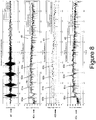
- FIG. 8 shows the received signal data at 41 by way of example.
- this data is cross-correlated in step 51 with the reference chirp data 27 to generate cross-correlated signal data 52.
- the vehicles 40 and the buoys 1 have synchronised clocks so the vehicles know the time to at which the buoys have transmitted the first pulse.
- a time-variable gain is applied to the cross-correlated signal, the gain increasing constantly with respect to time after to.
- the gain value 56 at that time is recorded and applied for subsequent parts of the cross-correlated signal data 52 at step 57.
- step 58 the four peaks in each of the signals 42a-c are determined by detecting when the signals have exceeded a predetermined threshold. Peaks 60a-c, 61a-c, 62a-c and 63a-c are shown in Figure 8 for the signals 42a-c respectively along with the threshold 43. It can be seen that these all have a roughly equal amplitude.
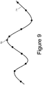
- Signal 71 shows the analogue input data generated by a transducer and amplifier on the vehicle.
- An analog to digital converter samples the signal 71 at various points shown by dots in Figure 9 .
- the amplitude at the peak 72 is calculated by interpolating between the sampled data values on each side of the peak.
- the sub-sampled peak data 70 is then filtered and processed at step 75 by rejecting any echoes (for instance echo 76 shown in Figure 8 ), and rejecting any peaks where the amplitude of the peak is too high relative to a previous peak, relative to some average peak value, or relative to a predetermined expected range of amplitude values.
- step 75 Another output of step 75 is a ray travel time 77 which gives the time of receipt of the first peak 60a-c relative to the known time to at which the first pulse was transmitted by the buoys 1a-c.
- Another output of step 75 is a set of filtered sub-sampled peak data which is decoded at step 78 in accordance with the grid property data 28 to determine the position 79 of the buoy.
- Figure 10 shows how the data 77, 79 is used by each vehicle 40a-c to determine its position.
- a raytracer algorithm determines a radial distance 81 in accordance with the ray travel time 77, a stored set of sound velocity profile data 82, and the vehicle depth 83 measured by a pressure sensor onboard the vehicle.
- This ray tracer algorithm 80 accounts for the fact that the sound waves will not travel in a straight line from the buoy to the vehicle due to the increase in pressure with depth.
- the vehicle now has the radial distance (or range) 81 and position 79 of each one of the three buoys 1a-c.
- This data is than analyzed by a trilateration algorithm at step 84 to calculate the position 86 of the vehicle.
- An input to the trilateration algorithm is the velocity 87 of the vehicle (as measured by onboard algorithms which may interpret the data from devices such as accelerometers and/or as calculated based on previous position measurements). This takes into account the fact that the vehicle may have moved between receiving the first pulse and the last pulse, so the output 86 of the algorithm 84 is the position of the vehicle at the time that the last pulse was received.
- pulse position modulation also provides a low computation overhead in decoding and encoding.
- a large fleet of such vehicles may be provided (potentially 100 or more) for instance for the purpose of accurately distributing a grid of seismic sensors over a wide area of the seabed.
- the use of pulse position modulation for encoding the acoustic transmissions ensures that there is a relatively large time difference ⁇ t between the pulses from a given buoy 1.
- This relatively large time difference provides time for any delayed versions of the original pulse, due to multipath effects, to be sufficiently attenuated so as not to cause interference with the current pulse.
- the likelihood of inter-symbol interference is reduced compared with other encoding methods, such as frequency shift keying, which transmit each symbol consecutively. With such encoding methods it is not possible to increase the time between symbol transmissions without dramatically reducing the data rate of the communication channel.
- the vehicle has an annular hull 100 with a duct 101; and a propulsion system for propelling the vehicle through the water comprising a pair of rotary propellers 105 housed within the duct on opposite sides of the central axis of the duct.
- the hull has an outer skin 100a defining the outer profile of the hull and an inner skin 100b defining the duct 101.
- the inner and outer skins meet at a leading edge and a trailing edge of the hull 100.
- the skins 100a and 100b are circular when viewed in cross-section at right angles to the central axis of the duct.
- Each propeller 105 is mounted on a thrust motor 107 and within a shroud 105b.
- Each motor 107 is pivotally mounted so the propeller/motor unit can be independently rotated up and down (relative to the orientation of Figure 11 ) to vary its angle of thrust relative to the central axis of the duct.
- the shroud and propeller of one of the propulsion units is not visible in Figure 1 , but it is identical to the shroud 105b and propeller 105 which are shown.
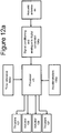
- FIG 12a is a block diagram showing the main functional elements of the vehicle.
- An acoustic antenna 44 (also shown in Figure 1 ) receives the acoustic signal pulses which are conditioned and analog-to-digital converted by a unit 106a and input to the processor 45 (also shown in Figure 1 ) along with clock signals from a time reference unit 106d and acceleration signals from accelerometers 106e.
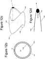
- the antenna 44 is shown in Figure 1 protruding from the hull of the vehicle for purposes of illustration, preferably the antenna 44 is conformal with the hull 100 as shown in Figures 12b-12d .
- the hull 100 has a port and starboard nose 109a,109b at one end, a lower tail 109c at the other end and an upper tail at which the antenna 44 is mounted.
- Figure 12b is a rear view of the vehicle with the propulsion units omitted
- Figure 12d is a section through the antenna 4.
- the antenna 44 is flush with the skins 100a,100b, and as shown in Figure 12d the rear edge of the antenna 44 is curved so as to form a curved trailing edge conforming with the hydrofoil section provided by the skins 100a,100b.
- the skins 100a,100b do not cover the antenna 44 so acoustic signals are not impeded.
- a signal wire 44a connects the antenna 44 with the electronics elements 106a,45,106d,106e which are housed entirely within the hull 100 between the inner and outer skins 100a,100b.
- the processor 45 operates as described above to determine the position of the vehicle.
- the processor 45 decodes the signal bursts to obtain the series of data sets encoded within them and determine the vehicle position.
- the processor 45 also controls the angle of thrust of the propellers via actuator motors 108.
- the processor 45 also controls the operation of the thrust motors 107 and is programmed to implement a sprint and drift control process as described below with reference to Figures 13-15 .
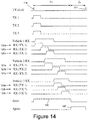
- Figure 13 shows three vehicles 40a-c and Figure 14 is a timing diagram showing a synchronous sprint and drift method of operating the vehicles 40a-c.
- the buoys 1a-c encode a series of data sets (each data set containing the X,Y and Z coordinates of the buoy at a given point in time), each data set being coded as a respective pulse train 25 as described above.
- These pulse trains 25 are then broadcast to the underwater vehicles, each pulse train 25 being initiated by a transmit clock pulse 110 shown in Figure 14 generated by a transmit clock on the buoy.
- the cycle repeats regularly every 7 seconds (a second transmit clock pulse 111 being shown in Figure 14 ). If the position of the buoy changes between cycles then the pulse train for the next cycle will also change - otherwise the pulse trains will not change.
- Figure 14 shows three pulse trains TX1-3 broadcast by buoys 1a-c respectively.
- the receive clocks 106d on the vehicles 40a-c are synchronized with the transmit clocks on the buoys 1a-c, so they also generate receive clock pulses (not shown) at exactly the same time as the TX clock pulses 110, 111 etc.
- Vehicle 40a receives the pulse trains TX1-3 from the three buoys at different times, and these are shown as three receive pulse trains 120a-120c. The time between the beginning of the first pulse train and the end of the last pulse train is illustrated by a receive pulse envelope Vehicle 1 RX
- Vehicle 40b also receives the pulse trains at different times, and these are shown as three receive pulse trains 121a-121c. The time between the beginning of the first pulse train and the end of the last pulse train is illustrated by a receive pulse envelope Vehicle 2 RX.
- Vehicle 40c also receives the pulse trains at different times, and these are shown as three receive pulse trains 122a-c. The time between the beginning of the first pulse train and the end of the last pulse train is illustrated by a receive pulse envelope Vehicle 3 RX
- the thrust motors 107 of the vehicles are operated synchronously by their respective processors 45 in a series of thrust pulses 125 separated by drift periods 126.
- the propellers 105 rotate at a relatively high rate during the thrust pulses 125 and at a relatively low (or zero) rate during the drift periods 126.
- Each drift period 126 has a fixed length of 5 seconds (starting at or shortly after the clock pulse 110) and each thrust pulse 125 has a fixed length of 2 seconds.
- the cycle then repeats regularly and indefinitely - a clock pulse 111 for the next cycle being shown in Figure 14
- the drift periods 126 of the vehicles 40a-c are timed relative to the receive clock pulse on the vehicle to ensure that that each pulse train arrives at the underwater vehicle during a drift period 126 and not during a thrust pulse 125 - with no part of any of the pulse trains arriving during a thrust pulse 125.
- the annular shape of the vehicle's hull ensures that water flows through the duct 101 and generates lift during the thrust pulses and during the drift periods.
- the high lift to drag ratio of the vehicle assists in maintenance of vehicle speed over ground during the drift periods.
- the propulsion systems of the vehicles are operated substantially synchronously such that the drift periods of all of the vehicles start and finish at substantially the same time.
- the duration of the thrust pulses 125 is much less than the duration of the quiet periods 126 for each vehicle (in this example the duration of the thrust pulses 125 is 40% of the duration of the drift periods 126).
- Vehicle 40a is the closest to the buoys 1a-c, so it receives the acoustic signals first. Its drift period 126a is timed to start just before the beginning of the first pulse train 120a and finish just after the end of the last pulse train 120c.
- the next closest vehicle is vehicle 40b, and its drift period 126b is timed to start just before the beginning of the first pulse train 121a and finish just after the end of the last pulse train 121c.
- the furthest vehicle is vehicle 40c, and its drift period 126c is timed to start just before the beginning of the first pulse train 122a and finish just after the end of the last pulse train 122c.
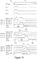
- the advantage of the asynchronous method of Figure 15 is that the length of the drift periods can be reduced compared to Figure 14 , so in this example the lengths of the drift periods 126a-c are slightly shorter than the lengths of the sprint periods 125a-c (summed over a 7 second cycle).
- the timings of the drift periods 126a-c can be varied in a number of ways.
- the timing can be varied by estimating a time of arrival of the pulse train from each buoy and varying the timing of the drift periods accordingly - later estimated time of arrival causing a delay in a start and/or finish time of the drift periods 126a-c.
- the time of arrival may be estimated for instance by measuring and recording the time of arrival of the pulse train in the previous cycle from each buoy (relative to to for that cycle).
- the estimate can be adjusted to account for any expected change caused by movement of the vehicle since the last cycle - for instance if the vehicle is moving towards the buoy then the drift period is advanced in the next cycle, and vice versa if the vehicle is moving away from the buoy.
- the estimate can be adjusted in accordance with both the speed and the direction of the motion of the vehicle - for instance if the vehicle is moving quickly towards the buoy then the drift period will be advanced more in the next cycle than if it is moving slowly towards the buoy.
- the timing can also be varied by measuring a proximity of each vehicle to other vehicles, and varying the timing of the drift periods accordingly - increased proximity causing an increase in the length of the drift periods. This ensures that a vehicle does not generate noise which interferes with neighboring vehicles which are close by.
Landscapes
- Engineering & Computer Science (AREA)
- Radar, Positioning & Navigation (AREA)
- Remote Sensing (AREA)
- Computer Networks & Wireless Communication (AREA)
- Physics & Mathematics (AREA)
- General Physics & Mathematics (AREA)
- Signal Processing (AREA)
- Mechanical Engineering (AREA)
- Aviation & Aerospace Engineering (AREA)
- Arrangements For Transmission Of Measured Signals (AREA)
- Position Fixing By Use Of Radio Waves (AREA)
- Measurement Of Velocity Or Position Using Acoustic Or Ultrasonic Waves (AREA)
Claims (15)
- Verfahren zur Kommunikation mit einem Unterwasserfahrzeug (40a), bei dem das Unterwasserfahrzeug ein Antriebssystem (107) zum Antreiben des Fahrzeugs durch das Wasser aufweist, wobei das Verfahren aufweist:a. ein Codieren einer Reihe von Datensätzen (25), um eine Reihe von codierten Datensignalen zu erzeugen,b. ein Übertragen der codierten Datensignale an das Unterwasserfahrzeug in einer Reihe von Signalfolgen (120a-c),c. ein Betreiben des Antriebssystems in einer Reihe von Schubimpulsen (125), die durch sich Treiben lassende Perioden (126) auf eine solche Weise getrennt sind, dass das Antriebssystem mit einer relativ hohen Geschwindigkeit während der Schubimpulse arbeitet und es mit einer relativ niedrigen Geschwindigkeit (oder null) während der sich Treiben lassenden Perioden arbeitet,d. ein zeitliches Einstellen der sich Treiben lassenden Perioden des Antriebssystems auf eine solche Weise, dass jede Signalfolge während der sich Treiben lassenden Periode und nicht während des Schubimpulses an dem Unterwasserfahrzeug ankommt, unde. ein Decodieren der Signalfolgen an dem Unterwasserfahrzeug, um die Reihe von Datensätzen zu erhalten.
- Verfahren nach Anspruch 1, bei dem die codierten Datensignale an das Unterwasserfahrzeug in einer Reihe von Signalfolgen durch einen ersten Sender (4) an einer ersten Stelle übertragen werden und wobei das Verfahren ferner aufweist:a. ein Codieren einer zweiten Reihe von Datensätzen, um eine zweite Reihe von codierten Datensignalen zu erzeugen,b. ein Übertragen der zweiten Reihe von codierten Datensignalen an das Unterwasserfahrzeug in einer zweiten Reihe von Signalfolgen (121a-c) durch einen zweiten Sender an einer zweiten Stelle, die von der ersten Stelle entfernt ist,c. ein zeitliches Einstellen der sich Treiben lassenden Perioden (126) des Antriebssystems auf eine solche Weise, dass jedes Signal in der zweiten Reihe an das Unterwasserfahrzeug während der sich Treiben lassenden Periode (126) und nicht während des Schubimpulses (125) ankommt, undd. ein Decodieren der zweiten Reihe von Signalfolgen an dem Unterwasserfahrzeug, um die zweite Reihe von Datensätzen zu erhalten.
- Verfahren zum Betreiben eines Unterwasserfahrzeugs, bei dem das Unterwasserfahrzeug einen ringförmigen Rumpf mit einem Kanal (101) und ein Antriebssystem (107) zum Antreiben des Fahrzeugs durch das Wasser aufweist, wobei das Verfahren aufweist:a. ein Betreiben des Antriebssystems in einer Reihe von Schubimpulsen (125), die durch sich Treiben lassende Perioden (126) auf eine solche Weise getrennt sind, dass das Antriebssystem mit einer relativ hohen Geschwindigkeit während der Schubimpulse arbeitet und es mit einer relativ niedrigen Geschwindigkeit (oder null) während der sich Treiben lassenden Perioden arbeitet, wobei Wasser durch den Kanal fließt und während der Schubimpulse und während der sich Treiben lassenden Perioden einen Auftrieb erzeugt,b. ein Empfangen einer Reihe von Signalfolgen an dem Fahrzeug,c. ein zeitliches Einstellen der sich Treiben lassenden Perioden des Antriebssystems auf eine solche Weise, dass jede Signalfolge während der sich Treiben lassenden Periode und nicht während des Schubimpulses an dem Unterwasserfahrzeug ankommt, undd. ein Decodieren der Signalfolgen, die an dem Unterwasserfahrzeug empfangen worden sind, um eine Reihe von Datensätzen zu erhalten, die in ihnen codiert sind.
- Verfahren zum Betreiben einer Anzahl von Unterwasserfahrzeugen (40a-c), bei dem jedes Unterwasserfahrzeug einen ringförmigen Rumpf mit einem Kanal und ein Antriebssystem zum Antreiben des Fahrzeugs durch das Wasser aufweist, wobei das Verfahren das Betreiben jedes Fahrzeugs durch das Verfahren nach Anspruch 3 umfasst.
- Verfahren zum Kommunizieren mit einer Anzahl von Unterwasserfahrzeugen (40a-c), bei dem das Verfahren die Kommunikation mit jedem Fahrzeug durch das Verfahren nach Anspruch 1 umfasst, wobei die codierten Datensignale gleichzeitig an die Unterwasserfahrzeuge in der Reihe von Signalfolgen gesendet werden.
- Verfahren zum Betreiben einer Anzahl von Unterwasserfahrzeugen (40a-c), um eine Reihe von Datensätzen zu empfangen, die zu ihnen gesendet worden sind, wobei jedes Unterwasserfahrzeug ein Antriebssystem zum Antreiben des Fahrzeugs durch das Wasser aufweist, wobei das Verfahren für jedes Fahrzeug aufweist:a. ein Betreiben des Antriebssystems in einer Reihe von Schubimpulsen (125), die durch sich Treiben lassende Perioden (126) auf eine solche Weise getrennt sind, dass das Antriebssystem mit einer relativ hohen Geschwindigkeit während der Schubimpulse arbeitet und es mit einer relativ niedrigen Geschwindigkeit (oder null) während der sich Treiben lassenden Perioden arbeitet,b. ein Empfangen einer Reihe von Signalfolgen (120a-c) an dem Fahrzeug,c. ein zeitliches Einstellen der sich Treiben lassenden Perioden des Antriebssystems auf eine solche Weise, dass jede Signalfolge während der sich Treiben lassenden Periode und nicht während des Schubimpulses an dem Unterwasserfahrzeug ankommt, undd. ein Decodieren der Signalfolgen, die an dem Unterwasserfahrzeug empfangen worden sind, um eine Reihe von Datensätzen zu erhalten, die in ihnen codiert sind.
- Verfahren nach Anspruch 4, 5 oder 6, bei dem das Antriebssystem der Fahrzeuge im Wesentlichen auf eine solche Weise synchron betrieben wird, so dass die sich Treiben lassenden Perioden aller Fahrzeuge im Wesentlichen zur gleichen Zeit beginnen und enden.
- Verfahren nach Anspruch 4, 5 oder 6, bei dem die Antriebssysteme der Fahrzeuge auf eine solche Weise asynchron betrieben werden, dass die sich Treiben lassenden Perioden von mindestens einem ersten der Fahrzeuge zu verschiedenen Zeiten zu mindestens einem zweiten der Fahrzeuge starten und / oder enden.
- Verfahren nach einem der vorhergehenden Ansprüche, welches ferner ein Messen eines Parameters für das Fahrzeug oder für jedes Fahrzeug und ein entsprechendes Verändern des zeitlichen Einstellens der sich Treiben lassenden Perioden aufweist.
- Verfahren nach einem der vorhergehenden Ansprüche, welches ferner ein Abschätzen einer Ankunftszeit der Signalfolgen an dem Fahrzeug oder an jedem Fahrzeug und ein entsprechendes Verändern des zeitlichen Einstellens der sich Treiben lassenden Perioden aufweist, wobei eine Verzögerung in der geschätzten Ankunftszeit eine Verzögerung in einer Start- und / oder Endzeit der sich Treiben lassenden Perioden bewirkt.
- Verfahren nach einem der vorhergehenden Ansprüche, welches ferner ein Messen einer Nähe des Fahrzeugs oder jedes Fahrzeugs zu anderen Fahrzeugen und ein entsprechendes Verändern des zeitlichen Einstellens der sich Treiben lassenden Perioden aufweist, wobei eine erhöhte Nähe eine Erhöhung der Länge der sich Treiben lassenden Perioden bewirkt.
- Verfahren nach einem der vorhergehenden Ansprüche, welches ferner ein Messen einer Bewegungsrichtung des Fahrzeugs oder jedes Fahrzeugs und ein entsprechendes Verändern des zeitlichen Einstellens der sich Treiben lassenden Perioden aufweist.
- Unterwasser-Kommunikationssystem, welches aufweist: einem Sender, der ausgestaltet ist, die Schritte a) und b) des Anspruchs 1 durchzuführen, und ein oder mehrere Unterwasserfahrzeuge (40a-c), die jeweils ein Antriebssystem zum Antreiben des Fahrzeugs durch das Wasser und ein Steuer- und Bearbeitungssystem aufweisen, das ausgestaltet, die Schritte c), d) und e) des Anspruchs 1 durchzuführen.
- Unterwasserfahrzeug, welches einen ringförmigen Rumpf mit einem Kanal (101), ein Antriebssystem (107) zum Antreiben des Fahrzeugs durch das Wasser und ein Steuer- und Bearbeitungssystem aufweist, das ausgestaltet ist, um das Fahrzeug durch das Verfahren nach Anspruch 3 zu betreiben.
- Anzahl an Unterwasserfahrzeugen (40a-c), die jeweils ein Antriebssystem zum Antreiben des Fahrzeugs durch das Wasser und ein Steuer- und Bearbeitungssystem aufweisen, welches ausgestaltet ist, das Fahrzeug zu betreiben, um die Schritte a. bis d. nach Anspruch 6 durchzuführen.
Applications Claiming Priority (2)
| Application Number | Priority Date | Filing Date | Title |
|---|---|---|---|
| GBGB1203671.1A GB201203671D0 (en) | 2012-03-02 | 2012-03-02 | Communication with an underwater vehicle |
| PCT/GB2013/050492 WO2013128188A1 (en) | 2012-03-02 | 2013-02-28 | Communication with an underwater vehicle |
Publications (2)
| Publication Number | Publication Date |
|---|---|
| EP2819918A1 EP2819918A1 (de) | 2015-01-07 |
| EP2819918B1 true EP2819918B1 (de) | 2017-10-18 |
Family
ID=46002995
Family Applications (1)
| Application Number | Title | Priority Date | Filing Date |
|---|---|---|---|
| EP13711933.5A Not-in-force EP2819918B1 (de) | 2012-03-02 | 2013-02-28 | Kommunikation mit einem unterwasserfahrzeug |
Country Status (6)
| Country | Link |
|---|---|
| US (1) | US9432129B2 (de) |
| EP (1) | EP2819918B1 (de) |
| CN (1) | CN104245500A (de) |
| GB (1) | GB201203671D0 (de) |
| RU (1) | RU2014138141A (de) |
| WO (1) | WO2013128188A1 (de) |
Families Citing this family (20)
| Publication number | Priority date | Publication date | Assignee | Title |
|---|---|---|---|---|
| US9090319B2 (en) | 2011-09-30 | 2015-07-28 | Seabed Geosolutions As | Autonomous underwater vehicle for marine seismic surveys |
| US9381986B2 (en) | 2012-11-21 | 2016-07-05 | Seabed Geosolutions B.V. | Jet-pump-based autonomous underwater vehicle and method for coupling to ocean bottom during marine seismic survey |
| US9457879B2 (en) | 2012-12-17 | 2016-10-04 | Seabed Geosolutions B.V. | Self-burying autonomous underwater vehicle and method for marine seismic surveys |
| US9845137B2 (en) | 2013-03-20 | 2017-12-19 | Seabed Geosolutions B.V. | Methods and underwater bases for using autonomous underwater vehicle for marine seismic surveys |
| FI124658B (en) * | 2013-10-18 | 2014-11-28 | Uwis Oy | Underwater tracking system |
| US9873496B2 (en) | 2014-10-29 | 2018-01-23 | Seabed Geosolutions B.V. | Deployment and retrieval of seismic autonomous underwater vehicles |
| RU2599902C1 (ru) * | 2015-09-08 | 2016-10-20 | Общество с ограниченной ответственностью "Лаборатория подводной связи и навигации" | Способ навигации подводных объектов и система для его осуществления |
| US10322783B2 (en) | 2015-10-16 | 2019-06-18 | Seabed Geosolutions B.V. | Seismic autonomous underwater vehicle |
| US20180126021A1 (en) * | 2016-11-04 | 2018-05-10 | Covidien Lp | Sterilization system and method |
| WO2018145012A1 (en) | 2017-02-06 | 2018-08-09 | Seabed Geosolutions B.V. | Ocean bottom seismic autonomous underwater vehicle |
| DE102017207231A1 (de) | 2017-04-28 | 2018-10-31 | Fraunhofer-Gesellschaft zur Förderung der angewandten Forschung e.V. | Navigationssystem für Unterwasserfahrzeuge |
| JP6980255B2 (ja) * | 2017-08-25 | 2021-12-15 | 国立研究開発法人海洋研究開発機構 | 水中観測システム及び水中観測システムの音波競合排除方法 |
| JP7003830B2 (ja) * | 2018-05-08 | 2022-01-21 | 株式会社Ihi | 通信状態制御システム |
| US11255998B2 (en) | 2018-05-17 | 2022-02-22 | Seabed Geosolutions B.V. | Cathedral body structure for an ocean bottom seismic node |
| EP4276008A3 (de) | 2018-05-23 | 2024-05-29 | Blue Ocean Seismic Services Limited | System zur autonomen datenerfassung |
| CN108791774A (zh) * | 2018-05-29 | 2018-11-13 | 中国科学院声学研究所 | 一种可通信与定位的水下航行器 |
| US20230066678A1 (en) * | 2020-02-20 | 2023-03-02 | Woods Hole Oceanographic Institution | Device, System and Method of Adaptive Autonomy with Sensor Swarming |
| CN112316403A (zh) * | 2020-11-04 | 2021-02-05 | 深圳乐漂科技有限公司 | 滑板车的漂移控制方法及控制系统 |
| US20240283547A1 (en) * | 2021-06-17 | 2024-08-22 | Sony Group Corporation | Communication device and communication system |
| US20230176176A1 (en) * | 2021-12-01 | 2023-06-08 | Bae Systems Information And Electronic Systems Integration Inc. | Underwater acoustic ranging and localization |
Family Cites Families (14)
| Publication number | Priority date | Publication date | Assignee | Title |
|---|---|---|---|---|
| US4203160A (en) * | 1960-12-30 | 1980-05-13 | The United States Of America As Represented By The Secretary Of The Navy | Submarine communication |
| GB1437806A (en) | 1973-09-26 | 1976-06-03 | Ferranti Ltd | Weapon guidance systems |
| US3885515A (en) | 1974-06-07 | 1975-05-27 | Us Navy | Rigid line array suspension system |
| SE455890B (sv) * | 1983-02-24 | 1988-08-15 | Philips Norden Ab | Sett att bestemma leget av en ljudkella inom ett vattenomrade samt anleggning for utforande av settet |
| US5119341A (en) * | 1991-07-17 | 1992-06-02 | The United States Of America As Represented By The Secretary Of The Air Force | Method for extending GPS to underwater applications |
| WO1993015567A2 (en) | 1992-02-01 | 1993-08-05 | Clive Ward | Shielding means for a radio-controlled craft |
| US5894450A (en) * | 1997-04-15 | 1999-04-13 | Massachusetts Institute Of Technology | Mobile underwater arrays |
| US5784339A (en) * | 1997-04-16 | 1998-07-21 | Ocean Vision Technology, Inc. | Underwater location and communication system |
| JP4307223B2 (ja) | 2003-11-28 | 2009-08-05 | 古野電気株式会社 | 水中探知装置 |
| US7512036B2 (en) * | 2005-08-16 | 2009-03-31 | Ocean Server Technology, Inc. | Underwater acoustic positioning system and method |
| US8005424B2 (en) | 2006-10-11 | 2011-08-23 | Japan Agency For Marine-Earth Science And Technology | Communication device and communication method of underwater vehicle |
| US8418642B2 (en) * | 2008-05-09 | 2013-04-16 | Irobot Corporation | Unmanned submersible vehicles and methods for operating the same in a body of liquid |
| CN101508334A (zh) * | 2009-03-23 | 2009-08-19 | 天津大学 | 混合型水下自主航行器分布式控制系统 |
| US8804461B2 (en) * | 2010-09-13 | 2014-08-12 | Incube Labs, Llc | Self-propelled buoy for monitoring underwater objects |
-
2012
- 2012-03-02 GB GBGB1203671.1A patent/GB201203671D0/en not_active Ceased
-
2013
- 2013-02-28 EP EP13711933.5A patent/EP2819918B1/de not_active Not-in-force
- 2013-02-28 WO PCT/GB2013/050492 patent/WO2013128188A1/en not_active Ceased
- 2013-02-28 US US14/380,824 patent/US9432129B2/en not_active Expired - Fee Related
- 2013-02-28 RU RU2014138141A patent/RU2014138141A/ru unknown
- 2013-02-28 CN CN201380008282.3A patent/CN104245500A/zh active Pending
Non-Patent Citations (1)
| Title |
|---|
| None * |
Also Published As
| Publication number | Publication date |
|---|---|
| RU2014138141A (ru) | 2016-04-27 |
| CN104245500A (zh) | 2014-12-24 |
| US20150019053A1 (en) | 2015-01-15 |
| US9432129B2 (en) | 2016-08-30 |
| EP2819918A1 (de) | 2015-01-07 |
| GB201203671D0 (en) | 2012-04-18 |
| WO2013128188A1 (en) | 2013-09-06 |
Similar Documents
| Publication | Publication Date | Title |
|---|---|---|
| EP2819918B1 (de) | Kommunikation mit einem unterwasserfahrzeug | |
| US9170319B2 (en) | Determining position of underwater node | |
| RU2599902C1 (ru) | Способ навигации подводных объектов и система для его осуществления | |
| US12019154B2 (en) | Underwater acoustic tracking and two way messaging system | |
| EP1882193B1 (de) | Verfahren und vorrichtung für unterwassergeopositionierung | |
| US4559621A (en) | Telemetering acoustic method for determining the relative position of a submerged object with respect to a vehicle and device therefor | |
| RU2561012C1 (ru) | Система определения и контроля местоположения подводного объекта | |
| RU2437114C1 (ru) | Система определения координат подводных объектов | |
| WO2017158659A1 (ja) | 音響測定装置、音響測定方法、動揺成分検出装置、動揺成分検出方法、マルチビーム音響測定装置及び開口合成ソナー | |
| CN103823210B (zh) | 一种非合作式星地双基地sar时频同步方法 | |
| CN109642954A (zh) | 用于定位水下设备的设备及方法 | |
| Han et al. | Signal design for underwater acoustic positioning systems based on orthogonal waveforms | |
| US20260009899A1 (en) | Method and System for Mapping a Region | |
| US9588223B2 (en) | Phase center alignment for fixed repetition rate synthetic aperture systems | |
| RU2529207C1 (ru) | Система навигации буксируемого подводного аппарата | |
| RU2700278C1 (ru) | Способ определения местоположения подводного объекта | |
| JPH07270519A (ja) | 水中作業機等の位置出し方法 | |
| JPH08136650A (ja) | 音響測位装置 | |
| RU2624994C1 (ru) | Способ определения относительного положения при межсамолетной навигации | |
| Wu et al. | Underwater long baseline localization based on doppler measurements for a fast-moving underwater vehicle | |
| RU2789636C1 (ru) | Абонентский приемник в составе гидроакустической системы позиционирования большой дальности для глубокого моря | |
| RU2794700C1 (ru) | Способ позиционирования подводного объекта на больших дистанциях | |
| RU2759199C1 (ru) | Способ измерения параметров движения объекта активным локатором | |
| Ghiotto et al. | Mobile submarine target strength measurement |
Legal Events
| Date | Code | Title | Description |
|---|---|---|---|
| PUAI | Public reference made under article 153(3) epc to a published international application that has entered the european phase |
Free format text: ORIGINAL CODE: 0009012 |
|
| 17P | Request for examination filed |
Effective date: 20140925 |
|
| AK | Designated contracting states |
Kind code of ref document: A1 Designated state(s): AL AT BE BG CH CY CZ DE DK EE ES FI FR GB GR HR HU IE IS IT LI LT LU LV MC MK MT NL NO PL PT RO RS SE SI SK SM TR |
|
| AX | Request for extension of the european patent |
Extension state: BA ME |
|
| DAX | Request for extension of the european patent (deleted) | ||
| GRAP | Despatch of communication of intention to grant a patent |
Free format text: ORIGINAL CODE: EPIDOSNIGR1 |
|
| INTG | Intention to grant announced |
Effective date: 20160722 |
|
| GRAJ | Information related to disapproval of communication of intention to grant by the applicant or resumption of examination proceedings by the epo deleted |
Free format text: ORIGINAL CODE: EPIDOSDIGR1 |
|
| STAA | Information on the status of an ep patent application or granted ep patent |
Free format text: STATUS: REQUEST FOR EXAMINATION WAS MADE |
|
| INTC | Intention to grant announced (deleted) | ||
| GRAP | Despatch of communication of intention to grant a patent |
Free format text: ORIGINAL CODE: EPIDOSNIGR1 |
|
| STAA | Information on the status of an ep patent application or granted ep patent |
Free format text: STATUS: GRANT OF PATENT IS INTENDED |
|
| INTG | Intention to grant announced |
Effective date: 20170102 |
|
| GRAJ | Information related to disapproval of communication of intention to grant by the applicant or resumption of examination proceedings by the epo deleted |
Free format text: ORIGINAL CODE: EPIDOSDIGR1 |
|
| STAA | Information on the status of an ep patent application or granted ep patent |
Free format text: STATUS: REQUEST FOR EXAMINATION WAS MADE |
|
| GRAP | Despatch of communication of intention to grant a patent |
Free format text: ORIGINAL CODE: EPIDOSNIGR1 |
|
| STAA | Information on the status of an ep patent application or granted ep patent |
Free format text: STATUS: GRANT OF PATENT IS INTENDED |
|
| INTC | Intention to grant announced (deleted) | ||
| INTG | Intention to grant announced |
Effective date: 20170523 |
|
| GRAS | Grant fee paid |
Free format text: ORIGINAL CODE: EPIDOSNIGR3 |
|
| GRAA | (expected) grant |
Free format text: ORIGINAL CODE: 0009210 |
|
| STAA | Information on the status of an ep patent application or granted ep patent |
Free format text: STATUS: THE PATENT HAS BEEN GRANTED |
|
| AK | Designated contracting states |
Kind code of ref document: B1 Designated state(s): AL AT BE BG CH CY CZ DE DK EE ES FI FR GB GR HR HU IE IS IT LI LT LU LV MC MK MT NL NO PL PT RO RS SE SI SK SM TR |
|
| REG | Reference to a national code |
Ref country code: GB Ref legal event code: FG4D |
|
| REG | Reference to a national code |
Ref country code: CH Ref legal event code: EP |
|
| REG | Reference to a national code |
Ref country code: AT Ref legal event code: REF Ref document number: 937687 Country of ref document: AT Kind code of ref document: T Effective date: 20171115 Ref country code: IE Ref legal event code: FG4D |
|
| REG | Reference to a national code |
Ref country code: DE Ref legal event code: R096 Ref document number: 602013028070 Country of ref document: DE |
|
| RAP2 | Party data changed (patent owner data changed or rights of a patent transferred) |
Owner name: AUTONOMOUS HOLDINGS LTD. |
|
| REG | Reference to a national code |
Ref country code: NL Ref legal event code: MP Effective date: 20171018 |
|
| REG | Reference to a national code |
Ref country code: LT Ref legal event code: MG4D |
|
| REG | Reference to a national code |
Ref country code: AT Ref legal event code: MK05 Ref document number: 937687 Country of ref document: AT Kind code of ref document: T Effective date: 20171018 |
|
| REG | Reference to a national code |
Ref country code: GB Ref legal event code: 732E Free format text: REGISTERED BETWEEN 20180301 AND 20180307 |
|
| PG25 | Lapsed in a contracting state [announced via postgrant information from national office to epo] |
Ref country code: NL Free format text: LAPSE BECAUSE OF FAILURE TO SUBMIT A TRANSLATION OF THE DESCRIPTION OR TO PAY THE FEE WITHIN THE PRESCRIBED TIME-LIMIT Effective date: 20171018 |
|
| RAP2 | Party data changed (patent owner data changed or rights of a patent transferred) |
Owner name: AUTONOMOUS ROBOTICS LIMITED |
|
| PG25 | Lapsed in a contracting state [announced via postgrant information from national office to epo] |
Ref country code: SE Free format text: LAPSE BECAUSE OF FAILURE TO SUBMIT A TRANSLATION OF THE DESCRIPTION OR TO PAY THE FEE WITHIN THE PRESCRIBED TIME-LIMIT Effective date: 20171018 Ref country code: LT Free format text: LAPSE BECAUSE OF FAILURE TO SUBMIT A TRANSLATION OF THE DESCRIPTION OR TO PAY THE FEE WITHIN THE PRESCRIBED TIME-LIMIT Effective date: 20171018 Ref country code: FI Free format text: LAPSE BECAUSE OF FAILURE TO SUBMIT A TRANSLATION OF THE DESCRIPTION OR TO PAY THE FEE WITHIN THE PRESCRIBED TIME-LIMIT Effective date: 20171018 Ref country code: ES Free format text: LAPSE BECAUSE OF FAILURE TO SUBMIT A TRANSLATION OF THE DESCRIPTION OR TO PAY THE FEE WITHIN THE PRESCRIBED TIME-LIMIT Effective date: 20171018 Ref country code: NO Free format text: LAPSE BECAUSE OF FAILURE TO SUBMIT A TRANSLATION OF THE DESCRIPTION OR TO PAY THE FEE WITHIN THE PRESCRIBED TIME-LIMIT Effective date: 20180118 |
|
| PG25 | Lapsed in a contracting state [announced via postgrant information from national office to epo] |
Ref country code: RS Free format text: LAPSE BECAUSE OF FAILURE TO SUBMIT A TRANSLATION OF THE DESCRIPTION OR TO PAY THE FEE WITHIN THE PRESCRIBED TIME-LIMIT Effective date: 20171018 Ref country code: BG Free format text: LAPSE BECAUSE OF FAILURE TO SUBMIT A TRANSLATION OF THE DESCRIPTION OR TO PAY THE FEE WITHIN THE PRESCRIBED TIME-LIMIT Effective date: 20180118 Ref country code: AT Free format text: LAPSE BECAUSE OF FAILURE TO SUBMIT A TRANSLATION OF THE DESCRIPTION OR TO PAY THE FEE WITHIN THE PRESCRIBED TIME-LIMIT Effective date: 20171018 Ref country code: LV Free format text: LAPSE BECAUSE OF FAILURE TO SUBMIT A TRANSLATION OF THE DESCRIPTION OR TO PAY THE FEE WITHIN THE PRESCRIBED TIME-LIMIT Effective date: 20171018 Ref country code: IS Free format text: LAPSE BECAUSE OF FAILURE TO SUBMIT A TRANSLATION OF THE DESCRIPTION OR TO PAY THE FEE WITHIN THE PRESCRIBED TIME-LIMIT Effective date: 20180218 Ref country code: GR Free format text: LAPSE BECAUSE OF FAILURE TO SUBMIT A TRANSLATION OF THE DESCRIPTION OR TO PAY THE FEE WITHIN THE PRESCRIBED TIME-LIMIT Effective date: 20180119 Ref country code: HR Free format text: LAPSE BECAUSE OF FAILURE TO SUBMIT A TRANSLATION OF THE DESCRIPTION OR TO PAY THE FEE WITHIN THE PRESCRIBED TIME-LIMIT Effective date: 20171018 |
|
| REG | Reference to a national code |
Ref country code: DE Ref legal event code: R097 Ref document number: 602013028070 Country of ref document: DE |
|
| PG25 | Lapsed in a contracting state [announced via postgrant information from national office to epo] |
Ref country code: DK Free format text: LAPSE BECAUSE OF FAILURE TO SUBMIT A TRANSLATION OF THE DESCRIPTION OR TO PAY THE FEE WITHIN THE PRESCRIBED TIME-LIMIT Effective date: 20171018 Ref country code: EE Free format text: LAPSE BECAUSE OF FAILURE TO SUBMIT A TRANSLATION OF THE DESCRIPTION OR TO PAY THE FEE WITHIN THE PRESCRIBED TIME-LIMIT Effective date: 20171018 Ref country code: CZ Free format text: LAPSE BECAUSE OF FAILURE TO SUBMIT A TRANSLATION OF THE DESCRIPTION OR TO PAY THE FEE WITHIN THE PRESCRIBED TIME-LIMIT Effective date: 20171018 Ref country code: SK Free format text: LAPSE BECAUSE OF FAILURE TO SUBMIT A TRANSLATION OF THE DESCRIPTION OR TO PAY THE FEE WITHIN THE PRESCRIBED TIME-LIMIT Effective date: 20171018 |
|
| PLBE | No opposition filed within time limit |
Free format text: ORIGINAL CODE: 0009261 |
|
| STAA | Information on the status of an ep patent application or granted ep patent |
Free format text: STATUS: NO OPPOSITION FILED WITHIN TIME LIMIT |
|
| PG25 | Lapsed in a contracting state [announced via postgrant information from national office to epo] |
Ref country code: PL Free format text: LAPSE BECAUSE OF FAILURE TO SUBMIT A TRANSLATION OF THE DESCRIPTION OR TO PAY THE FEE WITHIN THE PRESCRIBED TIME-LIMIT Effective date: 20171018 Ref country code: SM Free format text: LAPSE BECAUSE OF FAILURE TO SUBMIT A TRANSLATION OF THE DESCRIPTION OR TO PAY THE FEE WITHIN THE PRESCRIBED TIME-LIMIT Effective date: 20171018 Ref country code: RO Free format text: LAPSE BECAUSE OF FAILURE TO SUBMIT A TRANSLATION OF THE DESCRIPTION OR TO PAY THE FEE WITHIN THE PRESCRIBED TIME-LIMIT Effective date: 20171018 Ref country code: IT Free format text: LAPSE BECAUSE OF FAILURE TO SUBMIT A TRANSLATION OF THE DESCRIPTION OR TO PAY THE FEE WITHIN THE PRESCRIBED TIME-LIMIT Effective date: 20171018 |
|
| REG | Reference to a national code |
Ref country code: DE Ref legal event code: R119 Ref document number: 602013028070 Country of ref document: DE |
|
| REG | Reference to a national code |
Ref country code: CH Ref legal event code: PL |
|
| 26N | No opposition filed |
Effective date: 20180719 |
|
| PG25 | Lapsed in a contracting state [announced via postgrant information from national office to epo] |
Ref country code: MC Free format text: LAPSE BECAUSE OF FAILURE TO SUBMIT A TRANSLATION OF THE DESCRIPTION OR TO PAY THE FEE WITHIN THE PRESCRIBED TIME-LIMIT Effective date: 20171018 |
|
| REG | Reference to a national code |
Ref country code: IE Ref legal event code: MM4A |
|
| REG | Reference to a national code |
Ref country code: BE Ref legal event code: MM Effective date: 20180228 |
|
| PG25 | Lapsed in a contracting state [announced via postgrant information from national office to epo] |
Ref country code: CH Free format text: LAPSE BECAUSE OF NON-PAYMENT OF DUE FEES Effective date: 20180228 Ref country code: SI Free format text: LAPSE BECAUSE OF FAILURE TO SUBMIT A TRANSLATION OF THE DESCRIPTION OR TO PAY THE FEE WITHIN THE PRESCRIBED TIME-LIMIT Effective date: 20171018 Ref country code: LU Free format text: LAPSE BECAUSE OF NON-PAYMENT OF DUE FEES Effective date: 20180228 Ref country code: LI Free format text: LAPSE BECAUSE OF NON-PAYMENT OF DUE FEES Effective date: 20180228 |
|
| REG | Reference to a national code |
Ref country code: FR Ref legal event code: ST Effective date: 20181031 |
|
| PG25 | Lapsed in a contracting state [announced via postgrant information from national office to epo] |
Ref country code: IE Free format text: LAPSE BECAUSE OF NON-PAYMENT OF DUE FEES Effective date: 20180228 Ref country code: DE Free format text: LAPSE BECAUSE OF NON-PAYMENT OF DUE FEES Effective date: 20180901 |
|
| PG25 | Lapsed in a contracting state [announced via postgrant information from national office to epo] |
Ref country code: BE Free format text: LAPSE BECAUSE OF NON-PAYMENT OF DUE FEES Effective date: 20180228 Ref country code: FR Free format text: LAPSE BECAUSE OF NON-PAYMENT OF DUE FEES Effective date: 20180228 |
|
| PG25 | Lapsed in a contracting state [announced via postgrant information from national office to epo] |
Ref country code: MT Free format text: LAPSE BECAUSE OF NON-PAYMENT OF DUE FEES Effective date: 20180228 |
|
| PG25 | Lapsed in a contracting state [announced via postgrant information from national office to epo] |
Ref country code: TR Free format text: LAPSE BECAUSE OF FAILURE TO SUBMIT A TRANSLATION OF THE DESCRIPTION OR TO PAY THE FEE WITHIN THE PRESCRIBED TIME-LIMIT Effective date: 20171018 |
|
| PG25 | Lapsed in a contracting state [announced via postgrant information from national office to epo] |
Ref country code: PT Free format text: LAPSE BECAUSE OF FAILURE TO SUBMIT A TRANSLATION OF THE DESCRIPTION OR TO PAY THE FEE WITHIN THE PRESCRIBED TIME-LIMIT Effective date: 20171018 Ref country code: HU Free format text: LAPSE BECAUSE OF FAILURE TO SUBMIT A TRANSLATION OF THE DESCRIPTION OR TO PAY THE FEE WITHIN THE PRESCRIBED TIME-LIMIT; INVALID AB INITIO Effective date: 20130228 |
|
| PG25 | Lapsed in a contracting state [announced via postgrant information from national office to epo] |
Ref country code: CY Free format text: LAPSE BECAUSE OF FAILURE TO SUBMIT A TRANSLATION OF THE DESCRIPTION OR TO PAY THE FEE WITHIN THE PRESCRIBED TIME-LIMIT Effective date: 20171018 Ref country code: MK Free format text: LAPSE BECAUSE OF NON-PAYMENT OF DUE FEES Effective date: 20171018 |
|
| PG25 | Lapsed in a contracting state [announced via postgrant information from national office to epo] |
Ref country code: AL Free format text: LAPSE BECAUSE OF FAILURE TO SUBMIT A TRANSLATION OF THE DESCRIPTION OR TO PAY THE FEE WITHIN THE PRESCRIBED TIME-LIMIT Effective date: 20171018 |
|
| PGFP | Annual fee paid to national office [announced via postgrant information from national office to epo] |
Ref country code: GB Payment date: 20210215 Year of fee payment: 9 |
|
| GBPC | Gb: european patent ceased through non-payment of renewal fee |
Effective date: 20220228 |
|
| PG25 | Lapsed in a contracting state [announced via postgrant information from national office to epo] |
Ref country code: GB Free format text: LAPSE BECAUSE OF NON-PAYMENT OF DUE FEES Effective date: 20220228 |