EP2818655B1 - Abgasreinigungsvorrichtung für einen Kran für unebenes Gelände - Google Patents
Abgasreinigungsvorrichtung für einen Kran für unebenes Gelände Download PDFInfo
- Publication number
- EP2818655B1 EP2818655B1 EP14002190.8A EP14002190A EP2818655B1 EP 2818655 B1 EP2818655 B1 EP 2818655B1 EP 14002190 A EP14002190 A EP 14002190A EP 2818655 B1 EP2818655 B1 EP 2818655B1
- Authority
- EP
- European Patent Office
- Prior art keywords
- disposed
- lower frame
- exhaust emission
- emission control
- control device
- Prior art date
- Legal status (The legal status is an assumption and is not a legal conclusion. Google has not performed a legal analysis and makes no representation as to the accuracy of the status listed.)
- Active
Links
Images


Classifications
-
- B—PERFORMING OPERATIONS; TRANSPORTING
- B66—HOISTING; LIFTING; HAULING
- B66C—CRANES; LOAD-ENGAGING ELEMENTS OR DEVICES FOR CRANES, CAPSTANS, WINCHES, OR TACKLES
- B66C13/00—Other constructional features or details
- B66C13/52—Details of compartments for driving engines or motors or of operator's stands or cabins
-
- B—PERFORMING OPERATIONS; TRANSPORTING
- B01—PHYSICAL OR CHEMICAL PROCESSES OR APPARATUS IN GENERAL
- B01D—SEPARATION
- B01D53/00—Separation of gases or vapours; Recovering vapours of volatile solvents from gases; Chemical or biological purification of waste gases, e.g. engine exhaust gases, smoke, fumes, flue gases, aerosols
- B01D53/34—Chemical or biological purification of waste gases
- B01D53/92—Chemical or biological purification of waste gases of engine exhaust gases
- B01D53/94—Chemical or biological purification of waste gases of engine exhaust gases by catalytic processes
-
- F—MECHANICAL ENGINEERING; LIGHTING; HEATING; WEAPONS; BLASTING
- F01—MACHINES OR ENGINES IN GENERAL; ENGINE PLANTS IN GENERAL; STEAM ENGINES
- F01N—GAS-FLOW SILENCERS OR EXHAUST APPARATUS FOR MACHINES OR ENGINES IN GENERAL; GAS-FLOW SILENCERS OR EXHAUST APPARATUS FOR INTERNAL-COMBUSTION ENGINES
- F01N13/00—Exhaust or silencing apparatus characterised by constructional features
- F01N13/009—Exhaust or silencing apparatus characterised by constructional features having two or more separate purifying devices arranged in series
-
- F—MECHANICAL ENGINEERING; LIGHTING; HEATING; WEAPONS; BLASTING
- F01—MACHINES OR ENGINES IN GENERAL; ENGINE PLANTS IN GENERAL; STEAM ENGINES
- F01N—GAS-FLOW SILENCERS OR EXHAUST APPARATUS FOR MACHINES OR ENGINES IN GENERAL; GAS-FLOW SILENCERS OR EXHAUST APPARATUS FOR INTERNAL-COMBUSTION ENGINES
- F01N13/00—Exhaust or silencing apparatus characterised by constructional features
- F01N13/011—Exhaust or silencing apparatus characterised by constructional features having two or more purifying devices arranged in parallel
-
- F—MECHANICAL ENGINEERING; LIGHTING; HEATING; WEAPONS; BLASTING
- F01—MACHINES OR ENGINES IN GENERAL; ENGINE PLANTS IN GENERAL; STEAM ENGINES
- F01N—GAS-FLOW SILENCERS OR EXHAUST APPARATUS FOR MACHINES OR ENGINES IN GENERAL; GAS-FLOW SILENCERS OR EXHAUST APPARATUS FOR INTERNAL-COMBUSTION ENGINES
- F01N3/00—Exhaust or silencing apparatus having means for purifying, rendering innocuous, or otherwise treating exhaust
- F01N3/02—Exhaust or silencing apparatus having means for purifying, rendering innocuous, or otherwise treating exhaust for cooling, or for removing solid constituents of, exhaust
- F01N3/021—Exhaust or silencing apparatus having means for purifying, rendering innocuous, or otherwise treating exhaust for cooling, or for removing solid constituents of, exhaust by means of filters
- F01N3/033—Exhaust or silencing apparatus having means for purifying, rendering innocuous, or otherwise treating exhaust for cooling, or for removing solid constituents of, exhaust by means of filters in combination with other devices
- F01N3/035—Exhaust or silencing apparatus having means for purifying, rendering innocuous, or otherwise treating exhaust for cooling, or for removing solid constituents of, exhaust by means of filters in combination with other devices with catalytic reactors
-
- F—MECHANICAL ENGINEERING; LIGHTING; HEATING; WEAPONS; BLASTING
- F01—MACHINES OR ENGINES IN GENERAL; ENGINE PLANTS IN GENERAL; STEAM ENGINES
- F01N—GAS-FLOW SILENCERS OR EXHAUST APPARATUS FOR MACHINES OR ENGINES IN GENERAL; GAS-FLOW SILENCERS OR EXHAUST APPARATUS FOR INTERNAL-COMBUSTION ENGINES
- F01N3/00—Exhaust or silencing apparatus having means for purifying, rendering innocuous, or otherwise treating exhaust
- F01N3/08—Exhaust or silencing apparatus having means for purifying, rendering innocuous, or otherwise treating exhaust for rendering innocuous
- F01N3/10—Exhaust or silencing apparatus having means for purifying, rendering innocuous, or otherwise treating exhaust for rendering innocuous by thermal or catalytic conversion of noxious components of exhaust
- F01N3/105—General auxiliary catalysts, e.g. upstream or downstream of the main catalyst
- F01N3/106—Auxiliary oxidation catalysts
-
- F—MECHANICAL ENGINEERING; LIGHTING; HEATING; WEAPONS; BLASTING
- F01—MACHINES OR ENGINES IN GENERAL; ENGINE PLANTS IN GENERAL; STEAM ENGINES
- F01N—GAS-FLOW SILENCERS OR EXHAUST APPARATUS FOR MACHINES OR ENGINES IN GENERAL; GAS-FLOW SILENCERS OR EXHAUST APPARATUS FOR INTERNAL-COMBUSTION ENGINES
- F01N3/00—Exhaust or silencing apparatus having means for purifying, rendering innocuous, or otherwise treating exhaust
- F01N3/08—Exhaust or silencing apparatus having means for purifying, rendering innocuous, or otherwise treating exhaust for rendering innocuous
- F01N3/10—Exhaust or silencing apparatus having means for purifying, rendering innocuous, or otherwise treating exhaust for rendering innocuous by thermal or catalytic conversion of noxious components of exhaust
- F01N3/18—Exhaust or silencing apparatus having means for purifying, rendering innocuous, or otherwise treating exhaust for rendering innocuous by thermal or catalytic conversion of noxious components of exhaust characterised by methods of operation; Control
- F01N3/20—Exhaust or silencing apparatus having means for purifying, rendering innocuous, or otherwise treating exhaust for rendering innocuous by thermal or catalytic conversion of noxious components of exhaust characterised by methods of operation; Control specially adapted for catalytic conversion
- F01N3/206—Adding periodically or continuously substances to exhaust gases for promoting purification, e.g. catalytic material in liquid form, NOx reducing agents
- F01N3/2066—Selective catalytic reduction [SCR]
-
- F—MECHANICAL ENGINEERING; LIGHTING; HEATING; WEAPONS; BLASTING
- F01—MACHINES OR ENGINES IN GENERAL; ENGINE PLANTS IN GENERAL; STEAM ENGINES
- F01N—GAS-FLOW SILENCERS OR EXHAUST APPARATUS FOR MACHINES OR ENGINES IN GENERAL; GAS-FLOW SILENCERS OR EXHAUST APPARATUS FOR INTERNAL-COMBUSTION ENGINES
- F01N2340/00—Dimensional characteristics of the exhaust system, e.g. length, diameter or volume of the exhaust apparatus; Spatial arrangements of exhaust apparatuses
- F01N2340/04—Arrangement of the exhaust system relative to a vehicle or parts thereof
-
- F—MECHANICAL ENGINEERING; LIGHTING; HEATING; WEAPONS; BLASTING
- F01—MACHINES OR ENGINES IN GENERAL; ENGINE PLANTS IN GENERAL; STEAM ENGINES
- F01N—GAS-FLOW SILENCERS OR EXHAUST APPARATUS FOR MACHINES OR ENGINES IN GENERAL; GAS-FLOW SILENCERS OR EXHAUST APPARATUS FOR INTERNAL-COMBUSTION ENGINES
- F01N2590/00—Exhaust or silencing apparatus adapted to particular use, e.g. for military applications, airplanes, submarines
- F01N2590/08—Exhaust or silencing apparatus adapted to particular use, e.g. for military applications, airplanes, submarines for heavy duty applications, e.g. trucks, buses, tractors, locomotives
-
- Y—GENERAL TAGGING OF NEW TECHNOLOGICAL DEVELOPMENTS; GENERAL TAGGING OF CROSS-SECTIONAL TECHNOLOGIES SPANNING OVER SEVERAL SECTIONS OF THE IPC; TECHNICAL SUBJECTS COVERED BY FORMER USPC CROSS-REFERENCE ART COLLECTIONS [XRACs] AND DIGESTS
- Y02—TECHNOLOGIES OR APPLICATIONS FOR MITIGATION OR ADAPTATION AGAINST CLIMATE CHANGE
- Y02A—TECHNOLOGIES FOR ADAPTATION TO CLIMATE CHANGE
- Y02A50/00—TECHNOLOGIES FOR ADAPTATION TO CLIMATE CHANGE in human health protection, e.g. against extreme weather
- Y02A50/20—Air quality improvement or preservation, e.g. vehicle emission control or emission reduction by using catalytic converters
-
- Y—GENERAL TAGGING OF NEW TECHNOLOGICAL DEVELOPMENTS; GENERAL TAGGING OF CROSS-SECTIONAL TECHNOLOGIES SPANNING OVER SEVERAL SECTIONS OF THE IPC; TECHNICAL SUBJECTS COVERED BY FORMER USPC CROSS-REFERENCE ART COLLECTIONS [XRACs] AND DIGESTS
- Y02—TECHNOLOGIES OR APPLICATIONS FOR MITIGATION OR ADAPTATION AGAINST CLIMATE CHANGE
- Y02T—CLIMATE CHANGE MITIGATION TECHNOLOGIES RELATED TO TRANSPORTATION
- Y02T10/00—Road transport of goods or passengers
- Y02T10/10—Internal combustion engine [ICE] based vehicles
- Y02T10/12—Improving ICE efficiencies
Definitions
- the present invention relates to the structure of an exhaust emission control device for diesel engines to be mounted in rough terrain crane vehicles.
- the exhaust emission of diesel engines contain particulate matter (hereinafter referred to as "PM”), nitride oxide (hereinafter referred to as “NOx”), and the like.
- PM particulate matter
- NOx nitride oxide
- an exhaust emission control device or an after-treatment device.
- the exhaust emission control device contains a diesel particulate filter for collecting the PM (hereinafter referred to as "DPF”), a diesel oxidation catalyst (hereinafter referred to as "DOC") for removing the NOx, a decomposition reactor tube (hereinafter referred to as “DRT”), and a selective catalytic reduction (hereinafter referred to as "SCR”) as the constituent elements.
- DPF diesel particulate filter
- DOC diesel oxidation catalyst
- DTT decomposition reactor tube
- SCR selective catalytic reduction
- the diesel engine is mounted in various vehicles.
- the necessity of exhaust emission control treatment remains irrespective of the vehicle type and remains also in passenger automobiles, trucks, and construction vehicles, such as cranes.
- the constituent elements of the exhaust emission control device vary depending on the intended used and the size of vehicles and the mounting space thereof is naturally restricted. Therefore, the layout of the constituent elements of the exhaust emission control device has been variously proposed (as disclosed in, for example, Japanese Patent Laid-open Publication No. 2012-149535 ( JP2012-149535 A ) and Japanese Patent Laid-open Publication No. 2005-155404 ( JP2005-155404 A )).
- a wheel type working vehicle with a device for purifying nitrogen oxides is known from EP 2 474 672 A1 .
- a compact exhaust gas purification apparatus for a vehicle engine is known from EP 2 199 554 A1 .
- the rough terrain crane is generally a vehicle which has a four-wheel travel device capable of performing four-wheel drive and four-wheel steering and which allows vehicle travel and crane operation from a single driver seat.
- the rough terrain crane demonstrates excellent in small-radius turning performance and rough terrain traveling performance.
- a feature of the rough terrain crane resides in that the rough terrain crane is designed to be compact in order to demonstrate such special performance (merits), and the vehicle overall length is short, an engine is placed at the rear of the body, and all the crane operations are hydraulically controlled.
- the exhaust emission control device protrudes from a vehicle end portion, so that an overhang increases to increase the minimum rotation radius of the vehicle in some cases.
- the interaction between the exhaust emission control device and the driver seat is required to be avoided in the crane operation and the turning of the crane, so that the design flexibility decreases.
- the DOC, the DRT, and the SCR are disposed in parallel along the vehicle width direction, the overall width and the overall height of the vehicle increase, so that a dead angle expands in the crane operation and in traveling.
- the interaction of the exhaust emission control device and a counter weight and the like is also required to be avoided, and, also in this case, the design flexibility decreases. More specifically, in order to avoid such problems, a special device is required in the layout of the constituent elements of the exhaust emission control device.
- the invention has been made in view of the above-described circumstances. It is an object of the invention to provide an exhaust emission control device for rough terrain crane which secures excellent small-radius turning performance and rough terrain traveling performance with a compact body and obtains excellent visibility and a favorable visual field in crane operation and traveling.
- the exhaust emission control device for rough terrain crane of the invention is applied to a rough terrain crane, which has a carrier having a front axle and a rear axle, a boom device disposed on an upper side of the carrier, and a single operation unit for traveling and performing crane operation through a hydraulic actuator, in which the carrier has a lower frame, a front outrigger disposed on a lower side of a front end of the lower frame, a rear outrigger disposed on a lower side of a rear end of the lower frame, and an engine disposed on a rear end portion of the lower frame, which is for traveling and supplying hydraulic pressure.
- the exhaust emission control device for rough terrain crane has a diesel oxidation catalyst which is coupled to an exhaust pipe extending from the engine and to which exhaust emission is supplied, a decomposition reactor tube disposed on a downstream of the diesel oxidation catalyst, and a selective catalytic reduction disposed on a downstream of the decomposition reactor tube.
- the decomposition reactor tube is joined to the diesel oxidation catalyst or the selective catalytic reduction in series along the longitudinal direction of the lower frame and the diesel oxidation catalyst and the selective catalytic reduction are disposed in parallel in such a manner as to face each other along the lateral direction of the lower frame.
- the diesel oxidation catalyst is disposed along the longitudinal direction above a support member supporting a case of the rear outrigger and the selective catalytic reduction is disposed along the longitudinal direction on the upper side relative to the diesel oxidation catalyst.
- the diesel oxidation catalyst and the selective catalytic reduction face each other and are disposed in parallel in the lateral direction of the lower frame, i.e., in the vehicle width direction.
- a space required for disposing the exhaust emission control device in the lower frame is reduced as compared with the case where the devices are disposed in series.
- the decomposition reactor tube is joined to the diesel oxidation catalyst or the selective catalytic reduction in series along the longitudinal direction, the dimension in the lateral direction (vehicle width direction) required for mounting the exhaust emission control device is also reduced because the diesel oxidation catalyst and the selective catalytic reduction are disposed in parallel.
- the diesel oxidation catalyst is disposed along the longitudinal direction above the support member and the selective catalytic reduction is disposed above the diesel oxidation catalyst. More specifically, the diesel oxidation catalyst and the selective catalytic reduction which are disposed in parallel are disposed at a position that is adjacent to the engine and above the rear outrigger. In other words, the diesel oxidation catalyst, the selective catalytic reduction, and the decomposition reactor tube which are laid out in a compact manner are disposed on the left end or the right end of the rear end portion of the vehicle.
- the selective catalytic reduction is disposed at a position on the side of the engine relative to the diesel oxidation catalyst.
- the selective catalytic reduction is further shifted to the center of the vehicle to be disposed at a position close to the engine. More specifically, a layout in which the diesel oxidation catalyst, the selective catalytic reduction, and the decomposition reactor tube are disposed further utilizing the upper space of the rear outrigger is achieved. In addition, there is a merit in that the route of the exhaust emission control treatment is shortened.
- the support member may be a strengthening rib for coupling the lower frame and the case of the rear outrigger.
- the strengthening rib has a right triangle shape erected on the boundary of the lower frame and the case.
- the diesel oxidation catalyst and the selective catalytic reduction are disposed in parallel.
- the support member may be a hydraulic cylinder which is disposed between the lower frame and the case of the rear outrigger and presses the case against the ground surface.
- the rear outrigger is an X type.
- a dead space is formed around the hydraulic cylinder due to the design.
- the diesel oxidation catalyst and the selective catalytic reduction are disposed in parallel in the dead space.
- the exhaust emission control device for rough terrain crane of the invention is applied to a rough terrain crane, which has a carrier having a front axle and a rear axle, a boom device disposed on an upper side of the carrier, and a single operation unit traveling and performing crane operation through a hydraulic actuator, in which the carrier has a lower frame, a front outrigger disposed on a lower side of a front end of the lower frame, a rear outrigger disposed on a lower side of a rear end of the lower frame, and an engine disposed on a rear end portion of the lower frame, which is for traveling and supplying hydraulic pressure.
- the exhaust emission control device for rough terrain crane has a diesel particulate filter which is coupled to an exhaust pipe extending from the engine and to which exhaust emission is supplied, a decomposition reactor tube disposed on the downstream of the diesel particulate filter, and a selective catalytic reduction disposed on the downstream of the decomposition reactor tube.
- the decomposition reactor tube is joined to the diesel particulate filter or the selective catalytic reduction in series along the longitudinal direction of the lower frame and the diesel particulate filter and the selective catalytic reduction are disposed in parallel in such a manner as to face each other along the lateral direction of the lower frame.
- the diesel particulate filter is disposed along the longitudinal direction above a support member supporting a case of the rear outrigger and the selective catalytic reduction is disposed along the longitudinal direction on the upper side relative to the diesel particulate filter.
- the diesel particulate filter and the selective catalytic reduction face each other and are disposed in parallel in the lateral direction of the lower frame, i.e., in the vehicle width direction.
- a space required for disposing the exhaust emission control device in the lower frame is reduced as compared with the case where the devices are disposed in series.
- the decomposition reactor tube is joined to the diesel particulate filter or the selective catalytic reduction in series along the longitudinal direction, the dimension in the lateral direction (vehicle width direction) required for mounting the exhaust emission control device is also reduced because the diesel particulate filter and the selective catalytic reduction are disposed in parallel.
- the diesel particulate filter is disposed along the longitudinal direction above the support member and the selective catalytic reduction is disposed above the diesel particulate filter. More specifically, the diesel particulate filter and the selective catalytic reduction which are disposed in parallel are disposed at a position that is adjacent to the engine and above the rear outrigger. In other words, the diesel particulate filter, the selective catalytic reduction, and the decomposition reactor tube which are laid out in a compact manner are disposed on the left end or the right end of the rear end portion of the vehicle.
- the selective catalytic reduction is disposed at a position on the side of the engine relative to the diesel particulate filter.
- the selective catalytic reduction is further shifted to the center of the vehicle to be disposed at a position close to the engine. More specifically, a layout in which the diesel particulate filter, the selective catalytic reduction, and the decomposition reactor tube are disposed further utilizing the upper space of the rear outrigger is achieved. In addition, there is a merit in that the route of the exhaust emission control treatment is shortened.
- the support member may be a strengthening rib for coupling the lower frame and the case of the rear outrigger.
- the strengthening rib whose shape is a right triangle is erected on the boundary of the lower frame and the case.
- the diesel particulate filter and the selective catalytic reduction are disposed in parallel.
- the support member may be a hydraulic cylinder which is disposed between the lower frame and the case of the rear outrigger and presses the case against the ground surface.
- the rear outrigger is an X type.
- a dead space is formed around the hydraulic cylinder due to the design.
- the diesel particulate filter and the selective catalytic reduction are disposed in parallel in the dead space.
- the diesel oxidation catalyst, the selective catalytic reduction, and the decomposition reactor tube which are laid out in a compact manner are disposed on the left end or the right end of the rear end portion of the vehicle, and therefore, in the crane operation, e.g., the boom is turned and the like, an expansion of a so-called the drivers blind spot can be suppressed.
- an exhaust emission control device achieves to maintain the merits of the rough terrain crane. And also the exhaust emission control device achieves excellent visibility and a favorable visual field.
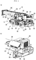
- FIGs. 1(a) and 1(b) are perspective views of a rough terrain crane 10 according to one embodiment of the invention, in which FIG. 1(a) is a perspective view of the appearance and FIG. 1(b) is a perspective view of the enlarged essential portion.
- the rough terrain crane 10 has a carrier 11 and a working unit 12.
- the carrier 11 has a lower frame 13 and the lower frame 13 is provided with a front axle 14 and a rear axle 15.
- a diesel engine serving as the drive source of the front axle 14 and the rear axle 15 is mounted on a rear end portion of the lower frame 13. Wheels 16 and 17 of the front axle 14 and the rear axle 15, respectively, are driven through a transmission which is not illustrated and are steered by a hydraulic cylinder which is not illustrated.
- a front outrigger 18 and a rear outrigger 19 are provided at a front end portion and a rear end portion, respectively, of the lower frame 13, so that the carrier 11 is stably grounded when operating the working unit 12.
- a hydraulic pump which supplies hydraulic pressure to a hydraulic motor and the working unit 12 is provided in the lower frame 13.
- a diesel engine 20 has an engine body which are not illustrated and an engine cover which covers the engine body. In this embodiment, the diesel engine includes also the engine cover.
- the working unit 12 has the lower frame 13. On the lower frame 13, a slewing base 22 is turnably mounted through a slewing bearing 21.
- a boom device 23 is coupled to the slewing base 22 through a raising/falling center pin. The boom device 23 is supported in such a manner as to be raised and failed with the raising/falling center pin.
- An expansion boom 24 contains an expansion cylinder which is not illustrated. By the operation of the expansion cylinder, the expansion boom 24 expands and contracts.
- the boom device 23 has a winch 27 which is driven by the hydraulic motor. By the operation of the winch 27, a work is moved up and down.
- a counter weight 28 is provided at a rear portion of the slewing base 22.
- a single operating unit 26 for driving the carrier 11 and operating the working unit 12 is provided through the slewing bearing 21.
- a feature of the rough terrain crane 10 resides in that an exhaust emission control device 30 described later in detail is mounted adjacent to the diesel engine 20.
- the exhaust emission control device 30 receives the supply of exhaust gas emitted from the diesel engine 20, and controls the same.
- the exhaust emission control device 30 has a diesel oxidation catalyst (hereinafter referred to as "DOC") 31, a selective catalytic reduction (hereinafter referred to as "SCR”) 32 which reduces nitrogen oxide in the exhaust emission through a predetermined reducing agent, and a decompression reactor tube (hereinafter referred to as "DRT”) 33 which supplies the reducing agent to the SCR 32 (refer to FIG. 2 ).
- DOC diesel oxidation catalyst
- SCR selective catalytic reduction
- DCT decompression reactor tube
- a feature of the rough terrain crane 10 according to this embodiment resides in that these devices are laid out as described later.
- the exhaust emission control device 30 can demonstrate excellent exhaust emission control performance while demonstrating the merits of the rough terrain crane to the greatest extent in a circumstance when the exhaust gas control becomes more and more strict in the future.
- the exhaust emission control device 30 is disposed on the left side as viewed from the rear of the vehicle as illustrated in FIG. 1(b) . As described above, the exhaust emission control device 30 has the DOC 31, DRT 33, and the SCR 32. A cover 34 is provided in these devices. The cover 34 protects the exhaust emission control device 30 from being exposed to rain and dust.
- the case 29 of the rear outrigger 19 is provided with a support member 35.
- the support member 35 contains a rib which strengthens the case 29 and is fixed to the case 29 and the lower frame 13.
- the support member 35 is disposed in such a manner as to bridge the case 29 and the side surface of the lower frame 13. Therefore, an upper surface 36 of the support member 35 inclines outwardly from the side surface of the lower frame 13 in an oblique downward direction.
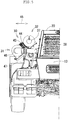
- FIGs. 2(a) and 2(b) are perspective views of the exhaust emission control device 30.
- FIG. 3 is a rear view of the enlarged essential portion of the carrier 11.
- FIGs. 2 and 3 illustrate the layout of the exhaust emission control device 30 in detail, in which a bracket for fixing the exhaust emission control device 30 and the like are omitted.
- the exhaust emission from the diesel engine 20 is first supplied to the DOC 31, and successively passes through the DRT 33 and the SCR 32 to be emitted as exhaust gas to the atmosphere from a tail pipe 37.
- the DOC is connected to an exhaust pipe 38 of the diesel engine 20.
- the structure of the DOC 31 is already known.
- the DOC 31 mainly aims at treating unburned fuel (HC and the like) and carbon monoxide (CO) contained in the exhaust emission and oxidizing nitrogen monoxide (NO) and nitrogen dioxide (NO2) contained in the exhaust emission.
- the DOC 31 has a function of oxidizing CO to carbon dioxide (CO2) to burn HC as an increase in the exhaust gas temperature.
- the DOC 31 has a casing and the outer shape of the casing is a cylindrical shape.
- the center axis line of the DOC 31 is along the front-back direction of the vehicle, i.e., a longitudinal direction 39 of the lower frame 13.
- a rear end 40 of the DOC 31 is disposed on the front side relative to a rear end 41 of the diesel engine 20.
- the DOC 31 does not protrude in a backward direction from the rear end 41 of the diesel engine 20.
- the exhaust emission emitted from the exhaust pipe 38 flows to the front in the longitudinal direction in the DOC 31.
- the SCR 32 reacts with a reducing agent (urea water in this embodiment) in the exhaust emission to reduce nitrogen oxide (NOX), and then finally converts the exhaust emission to a gas mixture of nitrogen (N2) and water (H2O) to emit the same to the atmosphere.
- a reducing agent urea water in this embodiment
- NOX nitrogen oxide
- N2O water
- the DRT33 supplies urea water (reducing agent) for reducing the NOX in the exhaust emission.
- urea water reducing agent
- hydrolysis occurs to generate ammonium (NH3), and then the NOX is reduced by the NH3.
- the DRT 33 has a cylindrical pipe 42 and a supply nozzle 43 connected thereto.
- the supply nozzle 43 is connected to a urea water tank which is not illustrated, and the urea water is ejected into the cylindrical pipe 42 at a predetermined pressure.
- the DRT 33 is disposed in series with the DOC 31. More specifically, the center axis line of the DRT 33 is in agreement with the center axis line of the DOC 31.
- the DRT33 is disposed on the front side in the longitudinal direction 39 of the DOC 31 and extends in the forward direction. The exhaust emission passing through the DOC 31 flows along the longitudinal direction 39 to flow into the cylindrical pipe 42 of the DRT 33, and then receives the supply of the urea water from the supply nozzle 43.
- the SCR 32 has a casing and the outer shape is formed into a cylindrical shape.
- the center axis line of the SCR 32 is along the longitudinal direction 39.
- the SCR 32 is disposed in parallel to the DOC 31.
- the SCR 32 and the DOC 31 are coupled with a U-shaped coupling pipe 44.
- the exhaust emission passing through the DRT 32 enters the coupling pipe 44, and then makes a U-turn to enter the SCR 32.
- the exhaust emission is controlled to be discharged as N2 and H2O as described above.
- the SCR 32 is disposed on the upper side relative to the DOC 31 and is disposed in parallel to the DOC 31 along a lateral direction of the lower frame 13. More specifically, the center axis line of the SCR 32 and the center axis line of the DOC 31 are in parallel to each other and the SCR 32 and the DOC 31 face each other in the lateral direction 45. Moreover, the SCR 32 and the DOC 31 are disposed above the support member 35. In particular, in this embodiment, the SCR 32 is disposed in such a manner as to be shifted to the diesel engine 20 side relative to the DOC 31 and both the SCR 32 and the DOC 31 are disposed along an upper surface 36 of the support member 35.
- the DOC 31 and the DRT 33 are disposed in series and the DOC 31 and the SCR 32 are disposed in parallel. More specifically, the exhaust emission control device 30 is laid out in a compact manner in the lower frame 13. Therefore, the exhaust emission control device 30 does not protrude backward relative to the rear end 41 of the diesel engine 30, so that an increase in the dimension in the longitudinal direction 39 (vehicle overall length direction) of the rough terrain crane 10 is prevented.
- all the DOC 31, the SCR 32, and the DRT 33 are not disposed in parallel and only the DOC 31 and the SCR 32 are disposed in parallel, and therefore the exhaust emission control device 30 does not protrude outward relative to the outer edge of the rear outrigger 19, so that an increase in the dimension in the lateral direction (vehicle width direction) of the rough terrain crane 10 is also prevented.
- the DOC 31 and the SCR 32 are vertically disposed and are disposed at a position adjacent to the diesel engine 20 above the rear outrigger 19, and therefore the exhaust emission control device 30 is disposed in a very compact manner utilizing the space of the left end or the right end of the rear end portion of the vehicle. Accordingly, even when the boom device 23 is slued in the crane operation, a region where the exhaust emission control device 30 blocks the view of an operator (so-called the drivers blind spot) does not expand.
- exhaust emission piping of the exhaust emission control device 30 is simplified and the piping route is shortened, and therefore there are merits in that a reduction in the exhaust emission temperature is suppressed and the exhaust performance of the exhaust emission control device 30 increases.
- the DOC 31 and the DRT 33 are disposed in series but the DRT 33 and the SCR 32 may be disposed in parallel. It is a matter of course that the DOC 31 and the SCR 32 are disposed in parallel even in this case.
- the SCR 32 is disposed on the side of the diesel engine 20 relative to the DOC 31. More specifically, the SCR 32 is further shifted to the side of the center of the vehicle and disposed at a position close to the diesel engine 20. Accordingly, there are merits in that the layout in which the space in the upper portion of the rear outrigger 19 is more effectively utilized is achieved and the route (piping) of the exhaust emission control device can be further simplified.
- the support member 35 contains a strengthening rib coupling the lower frame 13 and the case 29 of the rear outrigger 19.
- the upper surface 36 of the support member 35 inclines from the lower frame 13 to the case 29 and the DOC 31 and the SCR 32 are disposed along the upper surface 36. More specifically, the DOC 31 and the SCR 32 are more efficiently disposed in the space of a side portion of the diesel engine 20, so that a compact layout is achieved.
- FIGs. 4(a) and 4(b) are views illustrating the layout of the exhaust emission control device 30 according to a modification of this embodiment, in which FIG. 4(a) is a plan view and FIG. 4(b) is a rear view.
- FIG. 5 is a rear view illustrating the layout of the exhaust emission control device 30 according to this modification.
- the layout of the exhaust emission control device 30 of this modification is different from the layout of the exhaust emission control device 30 according to the above-described embodiment in that the rough terrain crane 10 has the so-called H-shaped rear outrigger 19 (refer to FIG. 2 ) in the above-described embodiment and, on the other hand, a so-called X-shaped outrigger (non-illustrated) is provided in this modification and the exhaust emission control device 30 is disposed above a jack cylinder suspending the rear outrigger (refer to FIGs. 4 and 5 ).
- the other configurations are the same as those of the above-described embodiment.
- the jack cylinder 14 also functions as the support member in the above-described embodiment. Then, by the elongation of the jack cylinder 47, the rear outrigger is pressed against the ground surface.
- the exhaust emission control device 30 has the DOC 31, the SCR 32, and the DRT 33 but a diesel particulate filter (hereinafter referred to a "DPF") may be provided in the place of the DOC 31. More specifically, the exhaust emission from the diesel engine 20 is first supplied to the DPF, and successively passes through the DRT 33 and the SCR 32 to be emitted to the atmosphere from a muffler 37.
- DPF diesel particulate filter
- the DPF is connected to the exhaust pipe 38 of the diesel engine 20.
- the structure of the DPF is already known and is a device of collecting particulate matter (hereinafter referred to as "PM") contained in the exhaust emission, and then continuously oxidizing the same to remove the same.
- the DPF also has a casing, and the outer shape of the casing is formed into a cylindrical shape.
- the center axis line of the DPF is disposed along the front-back direction of the vehicle, i.e., the longitudinal direction 39 of the lower frame 13 (refer to FIGs. 2 and 3 ).
- the DPF is disposed in such a manner that the rear end thereof does not protrude in the backward direction from the rear end 41 of the diesel engine 20.
- the exhaust emission emitted from the exhaust pile 38 flows in the forward direction in the longitudinal direction 39 in the DPF 31, enters the DRT 33, and then subjected to the same exhaust treatment as that of the above-described embodiment.
Landscapes
- Engineering & Computer Science (AREA)
- Chemical & Material Sciences (AREA)
- Mechanical Engineering (AREA)
- Combustion & Propulsion (AREA)
- General Engineering & Computer Science (AREA)
- Chemical Kinetics & Catalysis (AREA)
- Health & Medical Sciences (AREA)
- Materials Engineering (AREA)
- Toxicology (AREA)
- Biomedical Technology (AREA)
- Analytical Chemistry (AREA)
- General Chemical & Material Sciences (AREA)
- Oil, Petroleum & Natural Gas (AREA)
- Environmental & Geological Engineering (AREA)
- Exhaust Gas After Treatment (AREA)
- Processes For Solid Components From Exhaust (AREA)
- Exhaust Gas Treatment By Means Of Catalyst (AREA)
- Jib Cranes (AREA)
Claims (6)
- Abgasreinigungsvorrichtung (30) für einen Geländekran (10), wobei der Geländekran (10) umfasst:ein Trägerelement (11) mit einer Vorderachse (14) und einer Hinterachse (15);eine Auslegervorrichtung (23), welche auf der Oberseite des Trägerelements (11) montiert ist; undeine Ein-Personen-Bedieneinheit (26) zum Fahren und zur Durchführung der Kranbedienung durch einen Hydraulikantrieb, wobeidas Trägerelement (11) einen unteren Rahmen (13), eine auf einer unteren Ebene eines vorderen Endes des unteren Rahmens (13) vorgesehene vordere Stütze (18), eine auf einer unteren Ebene eines hinteren Endes des unteren Rahmens (13) vorgesehene hintere Stütze (19), und einen auf einem hinteren Endabschnitt des unteren Rahmens (13) vorgesehenen Antriebsmotor (20) aufweist, der zum Fahren sowie zur Erzeugung hydraulischen Drucks vorgesehen ist, und wobei die Abgasreinigungsvorrichtung (30) gekennzeichnet ist durch
einen Dieseloxidationskatalysator (31), der an ein aus dem Antriebsmotor (20) heraustretendes Abgasrohr (38) angeschlossen ist und durch welches Abgas geleitet wird, ein dem Dieseloxidationskatalysator (31) nachgelagertes Zersetzungsreaktorrohr (33), und eine dem Zersetzungsreaktorrohr (33) nachgelagerte selektive katalytische Reduktion (32),
wobei das Zersetzungsreaktorrohr (33) mit dem Dieseloxidationskatalysator (31) oder der selektiven katalytischen Reduktion (32) hintereinander in Längsrichtung (39) am unteren Rahmen (13) verbunden ist und der Dieseloxidationskatalysator (31) und die selektive katalytische Reduktion (32) parallel zueinander in einer Weise vorgesehen sind, dass sie sich in Seitwärtsrichtung (45) am unteren Rahmen (13) gegenüberliegen,
wobei der Dieseloxidationskatalysator (31) in Längsrichtung über einem Stützglied (35) angeordnet ist und ein Gehäuse (29) der hinteren Stütze (19) stützt und die selektive katalytische Reduktion (32) in Längsrichtung (39) auf einer höheren Ebene im Verhältnis zum Dieseloxidationskatalysator (31) angeordnet ist, und wobei die selektive katalytische Reduktion (32) bezogen auf den Dieseloxidationskatalysator (31) an einer Seite des Antriebsmotors (20) angeordnet ist. - Abgasreinigungsvorrichtung (30) für einen Geländekran (10) gemäß Anspruch 1, wobei das Stützteil (35) eine Verstärkungsrippe zur Verbindung des unteren Rahmens (13) mit dem Gehäuse(29) der hinteren Stütze (19) ist.
- Abgasreinigungsvorrichtung (30) für einen Geländekran (10) gemäß Anspruch 1, wobei das Stützteil (35) ein Hydraulikzylinder (47) ist, der zwischen dem unteren Rahmen (13) und dem Gehäuse (29) der hinteren Stütze (19) vorgesehen ist und das Gehäuse (29) gegen die Bodenfläche drückt.
- Abgasreinigungsvorrichtung (30) für einen Geländekran (10), wobei der Geländekran (10) umfasst:ein Trägerelement (11) mit einer Vorderachse (14) und einer Hinterachse (15);eine Auslegervorrichtung (23), welche auf der Oberseite des Trägerelements (11) montiert ist; undeine Ein-Personen-Bedieneinheit (26) zum Fahren und zur Durchführung der Kranbedienung durch einen Hydraulikantrieb, wobeidas Trägerelement (11) einen unteren Rahmen (13), eine auf einer unteren Ebene eines vorderen Endes des unteren Rahmens (13) vorgesehene vordere Stütze (18), eine auf einer unteren Ebene eines hinteren Endes des unteren Rahmens (13) vorgesehene hintere Stütze (19), und einen auf einem hinteren Endabschnitt des unteren Rahmens (13) vorgesehenen Antriebsmotor (20) aufweist, der zum Fahren sowie zur Erzeugung hydraulischen Drucks vorgesehen ist, und wobei die Abgasreinigungsvorrichtung (30) gekennzeichnet ist durch
einen Dieselpartikelfilter, der an ein aus dem Antriebsmotor (20) heraustretendes Abgasrohr (38) angeschlossen ist und durch welches Abgas geleitet wird, ein dem Dieselpartikelfilter nachgelagertes Zersetzungsreaktorrohr (33), und eine dem Zersetzungsreaktorrohr (33) nachgelagerte selektive katalytische Reduktion (32),
wobei das Zersetzungsreaktorrohr (33) mit dem Dieselpartikelfilter oder der selektiven katalytischen Reduktion (32) hintereinander in Längsrichtung (39) am unteren Rahmen (13) verbunden ist und der Dieselpartikelfilter und die selektive katalytische Reduktion (32) parallel zueinander in einer Weise vorgesehen sind, dass sie sich in Seitwärtsrichtung (45) am unteren Rahmen (13) gegenüberliegen,
und wobei der Dieselpartikelfilter in Längsrichtung (39) über einem Stützglied (35) vorgesehen ist und ein Gehäuse (29) der hinteren Stütze (19) stützt und die selektive katalytische Reduktion (32) in Längsrichtung auf einer höheren Ebene im Verhältnis zum Dieselpartikelfilter angeordnet ist, und wobei die selektive katalytische Reduktion (32) bezogen auf den Dieselpartikelfilter an einer Seite des Antriebsmotors (20) angeordnet ist. - Abgasreinigungsvorrichtung (30) für einen Geländekran (10) gemäß Anspruch 4, wobei das Stützteil eine Verstärkungsrippe zur Verbindung des unteren Rahmens (13) mit dem Gehäuse (29) der hinteren Stütze (19) ist.
- Abgasreinigungsvorrichtung (30) für einen Geländekran (10) gemäß Anspruch 4, wobei das Stützteil (35) ein Hydraulikzylinder (47) ist, der zwischen dem unteren Rahmen (13) und dem Gehäuse (29) der hinteren Stütze (19) vorgesehen ist und das Gehäuse (29) gegen die Bodenfläche drückt.
Applications Claiming Priority (1)
| Application Number | Priority Date | Filing Date | Title |
|---|---|---|---|
| JP2013135846A JP6190182B2 (ja) | 2013-06-28 | 2013-06-28 | ラフテレーンクレーン用排気浄化装置 |
Publications (2)
| Publication Number | Publication Date |
|---|---|
| EP2818655A1 EP2818655A1 (de) | 2014-12-31 |
| EP2818655B1 true EP2818655B1 (de) | 2017-01-04 |
Family
ID=51032887
Family Applications (1)
| Application Number | Title | Priority Date | Filing Date |
|---|---|---|---|
| EP14002190.8A Active EP2818655B1 (de) | 2013-06-28 | 2014-06-26 | Abgasreinigungsvorrichtung für einen Kran für unebenes Gelände |
Country Status (4)
| Country | Link |
|---|---|
| US (1) | US9469511B2 (de) |
| EP (1) | EP2818655B1 (de) |
| JP (1) | JP6190182B2 (de) |
| CA (1) | CA2853995C (de) |
Families Citing this family (8)
| Publication number | Priority date | Publication date | Assignee | Title |
|---|---|---|---|---|
| JP6297905B2 (ja) * | 2014-04-22 | 2018-03-20 | 日立建機株式会社 | 建設機械 |
| EP2985166B1 (de) * | 2014-08-14 | 2017-08-02 | CNH Industrial Italia S.p.A. | Abgasanlage für ein geländefahrzeug |
| JP6417920B2 (ja) * | 2014-12-19 | 2018-11-07 | 株式会社タダノ | ラフテレーンクレーン |
| US9670646B2 (en) * | 2015-03-10 | 2017-06-06 | Komatsu Ltd. | Working vehicle |
| US10071626B2 (en) * | 2015-04-28 | 2018-09-11 | Cnh Industrial America Llc | Exhaust after-treatment mounting arrangement |
| WO2016002973A1 (ja) * | 2015-08-21 | 2016-01-07 | 株式会社小松製作所 | 油圧ショベル |
| JP6731307B2 (ja) * | 2016-07-28 | 2020-07-29 | 株式会社加藤製作所 | 排気浄化装置の取付構造 |
| JP7273619B2 (ja) * | 2018-06-01 | 2023-05-15 | マニタウォック クレイン カンパニーズ, エルエルシー | クレーン下部走行体上のエンジン排気後処理システムのための取り付け配設 |
Family Cites Families (14)
| Publication number | Priority date | Publication date | Assignee | Title |
|---|---|---|---|---|
| BE630475A (de) * | 1962-04-02 | |||
| JP3959561B2 (ja) * | 1997-09-24 | 2007-08-15 | 株式会社加藤製作所 | ホイールクレーンのアウトリガ補強部材 |
| JP2005155404A (ja) * | 2003-11-25 | 2005-06-16 | Komatsu Ltd | 内燃機関の排気ガス浄化装置 |
| JP4785766B2 (ja) * | 2007-02-09 | 2011-10-05 | 日野自動車株式会社 | 排気浄化装置 |
| JP4286888B2 (ja) | 2007-09-28 | 2009-07-01 | 日産ディーゼル工業株式会社 | 排気浄化装置 |
| JP5319325B2 (ja) | 2009-02-24 | 2013-10-16 | 日野自動車株式会社 | 排気浄化装置の支持構造 |
| JP5054841B2 (ja) * | 2009-09-02 | 2012-10-24 | 日立建機株式会社 | ホイール式作業車両 |
| KR20120088764A (ko) * | 2010-05-31 | 2012-08-08 | 가부시키가이샤 고마쓰 세이사쿠쇼 | 작업 차량 |
| JP5630216B2 (ja) * | 2010-10-29 | 2014-11-26 | コベルコ建機株式会社 | 建設機械 |
| JP5664259B2 (ja) | 2011-01-17 | 2015-02-04 | 三菱ふそうトラック・バス株式会社 | 排気浄化装置 |
| WO2014061295A1 (ja) * | 2012-10-16 | 2014-04-24 | 株式会社小松製作所 | 油圧ショベル |
| JP5449517B1 (ja) * | 2012-12-20 | 2014-03-19 | 株式会社小松製作所 | 作業車両 |
| US8919486B2 (en) * | 2013-02-15 | 2014-12-30 | Komatsu Ltd. | Hydraulic excavator |
| JP5895931B2 (ja) * | 2013-12-27 | 2016-03-30 | コベルコ建機株式会社 | 建設機械 |
-
2013
- 2013-06-28 JP JP2013135846A patent/JP6190182B2/ja active Active
-
2014
- 2014-06-11 CA CA2853995A patent/CA2853995C/en active Active
- 2014-06-12 US US14/302,775 patent/US9469511B2/en active Active
- 2014-06-26 EP EP14002190.8A patent/EP2818655B1/de active Active
Non-Patent Citations (1)
| Title |
|---|
| None * |
Also Published As
| Publication number | Publication date |
|---|---|
| US9469511B2 (en) | 2016-10-18 |
| JP6190182B2 (ja) | 2017-08-30 |
| EP2818655A1 (de) | 2014-12-31 |
| CA2853995C (en) | 2019-09-17 |
| JP2015010531A (ja) | 2015-01-19 |
| CA2853995A1 (en) | 2014-12-28 |
| US20150001170A1 (en) | 2015-01-01 |
Similar Documents
| Publication | Publication Date | Title |
|---|---|---|
| EP2818655B1 (de) | Abgasreinigungsvorrichtung für einen Kran für unebenes Gelände | |
| KR102664511B1 (ko) | 작업 차량 | |
| EP3235774B1 (de) | Kran für unebenes gelände | |
| JP6131129B2 (ja) | ラフテレーンクレーン | |
| JP2022022274A (ja) | トラクタ | |
| EP3235674B1 (de) | Kran für unebenes gelände | |
| US9540979B2 (en) | Working vehicle | |
| WO2016163300A1 (ja) | ダンプトラック | |
| JP5914410B2 (ja) | 建設機械 | |
| JP2009275642A (ja) | エンジンの排気ガス浄化装置 | |
| JP7778669B2 (ja) | トラクタ | |
| WO2022181390A1 (ja) | ダンプトラック |
Legal Events
| Date | Code | Title | Description |
|---|---|---|---|
| PUAI | Public reference made under article 153(3) epc to a published international application that has entered the european phase |
Free format text: ORIGINAL CODE: 0009012 |
|
| 17P | Request for examination filed |
Effective date: 20140626 |
|
| AK | Designated contracting states |
Kind code of ref document: A1 Designated state(s): AL AT BE BG CH CY CZ DE DK EE ES FI FR GB GR HR HU IE IS IT LI LT LU LV MC MK MT NL NO PL PT RO RS SE SI SK SM TR |
|
| AX | Request for extension of the european patent |
Extension state: BA ME |
|
| R17P | Request for examination filed (corrected) |
Effective date: 20150626 |
|
| RBV | Designated contracting states (corrected) |
Designated state(s): AL AT BE BG CH CY CZ DE DK EE ES FI FR GB GR HR HU IE IS IT LI LT LU LV MC MK MT NL NO PL PT RO RS SE SI SK SM TR |
|
| 17Q | First examination report despatched |
Effective date: 20151124 |
|
| GRAP | Despatch of communication of intention to grant a patent |
Free format text: ORIGINAL CODE: EPIDOSNIGR1 |
|
| INTG | Intention to grant announced |
Effective date: 20160729 |
|
| GRAS | Grant fee paid |
Free format text: ORIGINAL CODE: EPIDOSNIGR3 |
|
| GRAA | (expected) grant |
Free format text: ORIGINAL CODE: 0009210 |
|
| AK | Designated contracting states |
Kind code of ref document: B1 Designated state(s): AL AT BE BG CH CY CZ DE DK EE ES FI FR GB GR HR HU IE IS IT LI LT LU LV MC MK MT NL NO PL PT RO RS SE SI SK SM TR |
|
| REG | Reference to a national code |
Ref country code: GB Ref legal event code: FG4D |
|
| REG | Reference to a national code |
Ref country code: CH Ref legal event code: EP |
|
| REG | Reference to a national code |
Ref country code: AT Ref legal event code: REF Ref document number: 859455 Country of ref document: AT Kind code of ref document: T Effective date: 20170115 |
|
| REG | Reference to a national code |
Ref country code: IE Ref legal event code: FG4D |
|
| REG | Reference to a national code |
Ref country code: DE Ref legal event code: R096 Ref document number: 602014005912 Country of ref document: DE |
|
| REG | Reference to a national code |
Ref country code: LT Ref legal event code: MG4D Ref country code: NL Ref legal event code: MP Effective date: 20170104 |
|
| REG | Reference to a national code |
Ref country code: AT Ref legal event code: MK05 Ref document number: 859455 Country of ref document: AT Kind code of ref document: T Effective date: 20170104 |
|
| PG25 | Lapsed in a contracting state [announced via postgrant information from national office to epo] |
Ref country code: NL Free format text: LAPSE BECAUSE OF FAILURE TO SUBMIT A TRANSLATION OF THE DESCRIPTION OR TO PAY THE FEE WITHIN THE PRESCRIBED TIME-LIMIT Effective date: 20170104 |
|
| PG25 | Lapsed in a contracting state [announced via postgrant information from national office to epo] |
Ref country code: IS Free format text: LAPSE BECAUSE OF FAILURE TO SUBMIT A TRANSLATION OF THE DESCRIPTION OR TO PAY THE FEE WITHIN THE PRESCRIBED TIME-LIMIT Effective date: 20170504 Ref country code: GR Free format text: LAPSE BECAUSE OF FAILURE TO SUBMIT A TRANSLATION OF THE DESCRIPTION OR TO PAY THE FEE WITHIN THE PRESCRIBED TIME-LIMIT Effective date: 20170405 Ref country code: FI Free format text: LAPSE BECAUSE OF FAILURE TO SUBMIT A TRANSLATION OF THE DESCRIPTION OR TO PAY THE FEE WITHIN THE PRESCRIBED TIME-LIMIT Effective date: 20170104 Ref country code: NO Free format text: LAPSE BECAUSE OF FAILURE TO SUBMIT A TRANSLATION OF THE DESCRIPTION OR TO PAY THE FEE WITHIN THE PRESCRIBED TIME-LIMIT Effective date: 20170404 Ref country code: LT Free format text: LAPSE BECAUSE OF FAILURE TO SUBMIT A TRANSLATION OF THE DESCRIPTION OR TO PAY THE FEE WITHIN THE PRESCRIBED TIME-LIMIT Effective date: 20170104 Ref country code: HR Free format text: LAPSE BECAUSE OF FAILURE TO SUBMIT A TRANSLATION OF THE DESCRIPTION OR TO PAY THE FEE WITHIN THE PRESCRIBED TIME-LIMIT Effective date: 20170104 |
|
| PG25 | Lapsed in a contracting state [announced via postgrant information from national office to epo] |
Ref country code: PL Free format text: LAPSE BECAUSE OF FAILURE TO SUBMIT A TRANSLATION OF THE DESCRIPTION OR TO PAY THE FEE WITHIN THE PRESCRIBED TIME-LIMIT Effective date: 20170104 Ref country code: BG Free format text: LAPSE BECAUSE OF FAILURE TO SUBMIT A TRANSLATION OF THE DESCRIPTION OR TO PAY THE FEE WITHIN THE PRESCRIBED TIME-LIMIT Effective date: 20170404 Ref country code: SE Free format text: LAPSE BECAUSE OF FAILURE TO SUBMIT A TRANSLATION OF THE DESCRIPTION OR TO PAY THE FEE WITHIN THE PRESCRIBED TIME-LIMIT Effective date: 20170104 Ref country code: AT Free format text: LAPSE BECAUSE OF FAILURE TO SUBMIT A TRANSLATION OF THE DESCRIPTION OR TO PAY THE FEE WITHIN THE PRESCRIBED TIME-LIMIT Effective date: 20170104 Ref country code: RS Free format text: LAPSE BECAUSE OF FAILURE TO SUBMIT A TRANSLATION OF THE DESCRIPTION OR TO PAY THE FEE WITHIN THE PRESCRIBED TIME-LIMIT Effective date: 20170104 Ref country code: PT Free format text: LAPSE BECAUSE OF FAILURE TO SUBMIT A TRANSLATION OF THE DESCRIPTION OR TO PAY THE FEE WITHIN THE PRESCRIBED TIME-LIMIT Effective date: 20170504 Ref country code: ES Free format text: LAPSE BECAUSE OF FAILURE TO SUBMIT A TRANSLATION OF THE DESCRIPTION OR TO PAY THE FEE WITHIN THE PRESCRIBED TIME-LIMIT Effective date: 20170104 Ref country code: LV Free format text: LAPSE BECAUSE OF FAILURE TO SUBMIT A TRANSLATION OF THE DESCRIPTION OR TO PAY THE FEE WITHIN THE PRESCRIBED TIME-LIMIT Effective date: 20170104 |
|
| REG | Reference to a national code |
Ref country code: DE Ref legal event code: R097 Ref document number: 602014005912 Country of ref document: DE |
|
| PG25 | Lapsed in a contracting state [announced via postgrant information from national office to epo] |
Ref country code: CZ Free format text: LAPSE BECAUSE OF FAILURE TO SUBMIT A TRANSLATION OF THE DESCRIPTION OR TO PAY THE FEE WITHIN THE PRESCRIBED TIME-LIMIT Effective date: 20170104 Ref country code: SK Free format text: LAPSE BECAUSE OF FAILURE TO SUBMIT A TRANSLATION OF THE DESCRIPTION OR TO PAY THE FEE WITHIN THE PRESCRIBED TIME-LIMIT Effective date: 20170104 Ref country code: RO Free format text: LAPSE BECAUSE OF FAILURE TO SUBMIT A TRANSLATION OF THE DESCRIPTION OR TO PAY THE FEE WITHIN THE PRESCRIBED TIME-LIMIT Effective date: 20170104 Ref country code: EE Free format text: LAPSE BECAUSE OF FAILURE TO SUBMIT A TRANSLATION OF THE DESCRIPTION OR TO PAY THE FEE WITHIN THE PRESCRIBED TIME-LIMIT Effective date: 20170104 |
|
| PLBE | No opposition filed within time limit |
Free format text: ORIGINAL CODE: 0009261 |
|
| STAA | Information on the status of an ep patent application or granted ep patent |
Free format text: STATUS: NO OPPOSITION FILED WITHIN TIME LIMIT |
|
| PG25 | Lapsed in a contracting state [announced via postgrant information from national office to epo] |
Ref country code: DK Free format text: LAPSE BECAUSE OF FAILURE TO SUBMIT A TRANSLATION OF THE DESCRIPTION OR TO PAY THE FEE WITHIN THE PRESCRIBED TIME-LIMIT Effective date: 20170104 Ref country code: SM Free format text: LAPSE BECAUSE OF FAILURE TO SUBMIT A TRANSLATION OF THE DESCRIPTION OR TO PAY THE FEE WITHIN THE PRESCRIBED TIME-LIMIT Effective date: 20170104 |
|
| PG25 | Lapsed in a contracting state [announced via postgrant information from national office to epo] |
Ref country code: MC Free format text: LAPSE BECAUSE OF FAILURE TO SUBMIT A TRANSLATION OF THE DESCRIPTION OR TO PAY THE FEE WITHIN THE PRESCRIBED TIME-LIMIT Effective date: 20170104 |
|
| REG | Reference to a national code |
Ref country code: CH Ref legal event code: PL |
|
| PG25 | Lapsed in a contracting state [announced via postgrant information from national office to epo] |
Ref country code: SI Free format text: LAPSE BECAUSE OF FAILURE TO SUBMIT A TRANSLATION OF THE DESCRIPTION OR TO PAY THE FEE WITHIN THE PRESCRIBED TIME-LIMIT Effective date: 20170104 |
|
| REG | Reference to a national code |
Ref country code: IE Ref legal event code: MM4A |
|
| REG | Reference to a national code |
Ref country code: FR Ref legal event code: ST Effective date: 20180228 |
|
| PG25 | Lapsed in a contracting state [announced via postgrant information from national office to epo] |
Ref country code: IE Free format text: LAPSE BECAUSE OF NON-PAYMENT OF DUE FEES Effective date: 20170626 Ref country code: CH Free format text: LAPSE BECAUSE OF NON-PAYMENT OF DUE FEES Effective date: 20170630 Ref country code: LU Free format text: LAPSE BECAUSE OF NON-PAYMENT OF DUE FEES Effective date: 20170626 Ref country code: LI Free format text: LAPSE BECAUSE OF NON-PAYMENT OF DUE FEES Effective date: 20170630 |
|
| PG25 | Lapsed in a contracting state [announced via postgrant information from national office to epo] |
Ref country code: FR Free format text: LAPSE BECAUSE OF NON-PAYMENT OF DUE FEES Effective date: 20170630 |
|
| REG | Reference to a national code |
Ref country code: BE Ref legal event code: MM Effective date: 20170630 |
|
| PG25 | Lapsed in a contracting state [announced via postgrant information from national office to epo] |
Ref country code: BE Free format text: LAPSE BECAUSE OF NON-PAYMENT OF DUE FEES Effective date: 20170630 |
|
| PG25 | Lapsed in a contracting state [announced via postgrant information from national office to epo] |
Ref country code: MT Free format text: LAPSE BECAUSE OF NON-PAYMENT OF DUE FEES Effective date: 20170626 |
|
| GBPC | Gb: european patent ceased through non-payment of renewal fee |
Effective date: 20180626 |
|
| PG25 | Lapsed in a contracting state [announced via postgrant information from national office to epo] |
Ref country code: GB Free format text: LAPSE BECAUSE OF NON-PAYMENT OF DUE FEES Effective date: 20180626 |
|
| PG25 | Lapsed in a contracting state [announced via postgrant information from national office to epo] |
Ref country code: HU Free format text: LAPSE BECAUSE OF FAILURE TO SUBMIT A TRANSLATION OF THE DESCRIPTION OR TO PAY THE FEE WITHIN THE PRESCRIBED TIME-LIMIT; INVALID AB INITIO Effective date: 20140626 |
|
| PG25 | Lapsed in a contracting state [announced via postgrant information from national office to epo] |
Ref country code: CY Free format text: LAPSE BECAUSE OF FAILURE TO SUBMIT A TRANSLATION OF THE DESCRIPTION OR TO PAY THE FEE WITHIN THE PRESCRIBED TIME-LIMIT Effective date: 20170104 |
|
| PG25 | Lapsed in a contracting state [announced via postgrant information from national office to epo] |
Ref country code: MK Free format text: LAPSE BECAUSE OF FAILURE TO SUBMIT A TRANSLATION OF THE DESCRIPTION OR TO PAY THE FEE WITHIN THE PRESCRIBED TIME-LIMIT Effective date: 20170104 |
|
| PG25 | Lapsed in a contracting state [announced via postgrant information from national office to epo] |
Ref country code: TR Free format text: LAPSE BECAUSE OF FAILURE TO SUBMIT A TRANSLATION OF THE DESCRIPTION OR TO PAY THE FEE WITHIN THE PRESCRIBED TIME-LIMIT Effective date: 20170104 |
|
| PG25 | Lapsed in a contracting state [announced via postgrant information from national office to epo] |
Ref country code: AL Free format text: LAPSE BECAUSE OF FAILURE TO SUBMIT A TRANSLATION OF THE DESCRIPTION OR TO PAY THE FEE WITHIN THE PRESCRIBED TIME-LIMIT Effective date: 20170104 |
|
| PGFP | Annual fee paid to national office [announced via postgrant information from national office to epo] |
Ref country code: DE Payment date: 20250625 Year of fee payment: 12 |
|
| PGFP | Annual fee paid to national office [announced via postgrant information from national office to epo] |
Ref country code: IT Payment date: 20250626 Year of fee payment: 12 |