EP2816362A1 - Conductivity inspection apparatus and conductivity inspection method - Google Patents
Conductivity inspection apparatus and conductivity inspection method Download PDFInfo
- Publication number
- EP2816362A1 EP2816362A1 EP13749918.2A EP13749918A EP2816362A1 EP 2816362 A1 EP2816362 A1 EP 2816362A1 EP 13749918 A EP13749918 A EP 13749918A EP 2816362 A1 EP2816362 A1 EP 2816362A1
- Authority
- EP
- European Patent Office
- Prior art keywords
- needles
- battery
- laminate film
- film
- stage
- Prior art date
- Legal status (The legal status is an assumption and is not a legal conclusion. Google has not performed a legal analysis and makes no representation as to the accuracy of the status listed.)
- Granted
Links
- 238000007689 inspection Methods 0.000 title claims description 54
- 238000000034 method Methods 0.000 title claims description 11
- 239000011888 foil Substances 0.000 claims abstract description 50
- 229910052751 metal Inorganic materials 0.000 claims abstract description 19
- 239000002184 metal Substances 0.000 claims abstract description 19
- 239000011347 resin Substances 0.000 claims description 41
- 229920005989 resin Polymers 0.000 claims description 41
- 239000005001 laminate film Substances 0.000 description 64
- 229910052782 aluminium Inorganic materials 0.000 description 32
- XAGFODPZIPBFFR-UHFFFAOYSA-N aluminium Chemical compound [Al] XAGFODPZIPBFFR-UHFFFAOYSA-N 0.000 description 32
- 238000010248 power generation Methods 0.000 description 16
- 238000009413 insulation Methods 0.000 description 7
- 238000010586 diagram Methods 0.000 description 5
- 238000003780 insertion Methods 0.000 description 5
- 230000037431 insertion Effects 0.000 description 5
- 230000000694 effects Effects 0.000 description 4
- 239000012212 insulator Substances 0.000 description 4
- 230000003247 decreasing effect Effects 0.000 description 3
- XEEYBQQBJWHFJM-UHFFFAOYSA-N Iron Chemical compound [Fe] XEEYBQQBJWHFJM-UHFFFAOYSA-N 0.000 description 2
- RYGMFSIKBFXOCR-UHFFFAOYSA-N Copper Chemical compound [Cu] RYGMFSIKBFXOCR-UHFFFAOYSA-N 0.000 description 1
- 230000001154 acute effect Effects 0.000 description 1
- 239000000853 adhesive Substances 0.000 description 1
- 230000001070 adhesive effect Effects 0.000 description 1
- 229910045601 alloy Inorganic materials 0.000 description 1
- 239000000956 alloy Substances 0.000 description 1
- 230000015556 catabolic process Effects 0.000 description 1
- 230000008602 contraction Effects 0.000 description 1
- 229910052802 copper Inorganic materials 0.000 description 1
- 239000010949 copper Substances 0.000 description 1
- 229910052742 iron Inorganic materials 0.000 description 1
- 230000003252 repetitive effect Effects 0.000 description 1
- 238000010998 test method Methods 0.000 description 1
- 238000004804 winding Methods 0.000 description 1
Images


Classifications
-
- G—PHYSICS
- G01—MEASURING; TESTING
- G01R—MEASURING ELECTRIC VARIABLES; MEASURING MAGNETIC VARIABLES
- G01R1/00—Details of instruments or arrangements of the types included in groups G01R5/00 - G01R13/00 and G01R31/00
- G01R1/02—General constructional details
- G01R1/06—Measuring leads; Measuring probes
- G01R1/067—Measuring probes
- G01R1/06711—Probe needles; Cantilever beams; "Bump" contacts; Replaceable probe pins
- G01R1/06733—Geometry aspects
- G01R1/0675—Needle-like
-
- G—PHYSICS
- G01—MEASURING; TESTING
- G01R—MEASURING ELECTRIC VARIABLES; MEASURING MAGNETIC VARIABLES
- G01R19/00—Arrangements for measuring currents or voltages or for indicating presence or sign thereof
- G01R19/145—Indicating the presence of current or voltage
-
- G—PHYSICS
- G01—MEASURING; TESTING
- G01R—MEASURING ELECTRIC VARIABLES; MEASURING MAGNETIC VARIABLES
- G01R31/00—Arrangements for testing electric properties; Arrangements for locating electric faults; Arrangements for electrical testing characterised by what is being tested not provided for elsewhere
- G01R31/50—Testing of electric apparatus, lines, cables or components for short-circuits, continuity, leakage current or incorrect line connections
-
- H—ELECTRICITY
- H01—ELECTRIC ELEMENTS
- H01M—PROCESSES OR MEANS, e.g. BATTERIES, FOR THE DIRECT CONVERSION OF CHEMICAL ENERGY INTO ELECTRICAL ENERGY
- H01M10/00—Secondary cells; Manufacture thereof
- H01M10/42—Methods or arrangements for servicing or maintenance of secondary cells or secondary half-cells
- H01M10/48—Accumulators combined with arrangements for measuring, testing or indicating the condition of cells, e.g. the level or density of the electrolyte
-
- G—PHYSICS
- G01—MEASURING; TESTING
- G01R—MEASURING ELECTRIC VARIABLES; MEASURING MAGNETIC VARIABLES
- G01R31/00—Arrangements for testing electric properties; Arrangements for locating electric faults; Arrangements for electrical testing characterised by what is being tested not provided for elsewhere
- G01R31/36—Arrangements for testing, measuring or monitoring the electrical condition of accumulators or electric batteries, e.g. capacity or state of charge [SoC]
- G01R31/385—Arrangements for measuring battery or accumulator variables
-
- G—PHYSICS
- G01—MEASURING; TESTING
- G01R—MEASURING ELECTRIC VARIABLES; MEASURING MAGNETIC VARIABLES
- G01R31/00—Arrangements for testing electric properties; Arrangements for locating electric faults; Arrangements for electrical testing characterised by what is being tested not provided for elsewhere
- G01R31/50—Testing of electric apparatus, lines, cables or components for short-circuits, continuity, leakage current or incorrect line connections
- G01R31/54—Testing for continuity
-
- H—ELECTRICITY
- H01—ELECTRIC ELEMENTS
- H01M—PROCESSES OR MEANS, e.g. BATTERIES, FOR THE DIRECT CONVERSION OF CHEMICAL ENERGY INTO ELECTRICAL ENERGY
- H01M10/00—Secondary cells; Manufacture thereof
- H01M10/04—Construction or manufacture in general
- H01M10/0413—Large-sized flat cells or batteries for motive or stationary systems with plate-like electrodes
-
- H—ELECTRICITY
- H01—ELECTRIC ELEMENTS
- H01M—PROCESSES OR MEANS, e.g. BATTERIES, FOR THE DIRECT CONVERSION OF CHEMICAL ENERGY INTO ELECTRICAL ENERGY
- H01M10/00—Secondary cells; Manufacture thereof
- H01M10/04—Construction or manufacture in general
- H01M10/0436—Small-sized flat cells or batteries for portable equipment
-
- Y—GENERAL TAGGING OF NEW TECHNOLOGICAL DEVELOPMENTS; GENERAL TAGGING OF CROSS-SECTIONAL TECHNOLOGIES SPANNING OVER SEVERAL SECTIONS OF THE IPC; TECHNICAL SUBJECTS COVERED BY FORMER USPC CROSS-REFERENCE ART COLLECTIONS [XRACs] AND DIGESTS
- Y02—TECHNOLOGIES OR APPLICATIONS FOR MITIGATION OR ADAPTATION AGAINST CLIMATE CHANGE
- Y02E—REDUCTION OF GREENHOUSE GAS [GHG] EMISSIONS, RELATED TO ENERGY GENERATION, TRANSMISSION OR DISTRIBUTION
- Y02E60/00—Enabling technologies; Technologies with a potential or indirect contribution to GHG emissions mitigation
- Y02E60/10—Energy storage using batteries
-
- Y—GENERAL TAGGING OF NEW TECHNOLOGICAL DEVELOPMENTS; GENERAL TAGGING OF CROSS-SECTIONAL TECHNOLOGIES SPANNING OVER SEVERAL SECTIONS OF THE IPC; TECHNICAL SUBJECTS COVERED BY FORMER USPC CROSS-REFERENCE ART COLLECTIONS [XRACs] AND DIGESTS
- Y02—TECHNOLOGIES OR APPLICATIONS FOR MITIGATION OR ADAPTATION AGAINST CLIMATE CHANGE
- Y02P—CLIMATE CHANGE MITIGATION TECHNOLOGIES IN THE PRODUCTION OR PROCESSING OF GOODS
- Y02P70/00—Climate change mitigation technologies in the production process for final industrial or consumer products
- Y02P70/50—Manufacturing or production processes characterised by the final manufactured product
Definitions
- This invention relates to a conductivity inspection apparatus and a method thereof, and more specifically to a conductivity inspection apparatus and a method thereof which are configured to inspect a conductive state of a structural member covered by a film in which a metal foil is sandwiched between resin films.
- the internal power generation element and the laminate film are insulated so as not to leak the current to the laminate film which is the outer covering member (package) (cf. background art of the patent document 1).
- the conventional art it is possible to test the insulating state between the power generation element and the laminate film by inserting the needle from the surface of the laminate film, and measuring the resistance between this needle and the lead electrode extending from the power generation element.
- an object of the present invention to provide a conductivity inspection apparatus and a method thereof which are configured to inspect an electrical conductive state of a structural member which is covered with an outer covering film in which a metal foil is sandwiched by resin films.
- a conductivity inspection method comprises: inserting at least two needles from a surface of an outer covering film of a structural member covered with the outer covering film having a stacked film configuration in which a metal foil is sandwiched by resin films, to reach the metal foil; and inspecting a conduction state between a member within the structural member, and the two needles.
- At least two needles are inserted. Accordingly, when one of the at least two needles is contacted on the metal foil, it is possible to inspect the conduction state. Consequently, it is possible to decrease the generation of the inspection failure, and to improve the reliability of the inspection, relative to a case in which the inspection is performed by one needle.
- FIG. 1 is a schematic view for illustrating a conductivity inspection apparatus of a battery covered with a laminate film (an outer covering film) in a first embodiment.
- This conductivity inspection apparatus 1 includes two conductive needles 11 and 12, a support portion (section) 13 integrally supporting the two needles 11 and 12, an air cylinder 14 arranged to move the support portion 13 in upward and downward directions, and a stage 15 holding the battery at a predetermined position. Moreover, the support portion (section) 13 is provided with an elastic pad 16 which is arranged to press tabs of the battery against the stage 15, at a position of the tabs of the battery which is mounted on the stage 15, as described below.
- Two needles 11 and 12 are not specifically limited as long as the needles are conductive members such as a stainless, a copper, an iron, and other alloys.
- a tip end of each of the needles has acute angle.
- a middle portion (body portion) of each of the needles has a thickness of about 0.3-1 mm. Needless to say, the needles are not limited to these as long as the needles can be inserted in the laminate film.
- the air cylinder 14 is arranged to move the support portion 13 apart from and toward the stage 15. That is, in FIG. 1 , the air cylinder 14 moves the support portion 13 in the upward and downward directions.
- the support portion 13 integrally supports the two needles 11 and 12. Accordingly, it is possible to always move the two needles 11 and 12 together. Moreover, at the same time, the elastic pad 16 is moved together.
- a portion of the air cylinder 14 which is not operated is fixed to 19 such as a support (fulcrum) and a frame (not shown).
- FIG. 2 is a plan view showing a battery mounting surface of the stage 15.
- holes 17 are opened in the stage 15 at positions corresponding to the two needles 11 and 12.
- Each of the holes 17 can have any size as long as the needles 11 and 12 are not contacted on the stage 15 when the needles 11 and 12 are moved in the downward direction.
- the holes 17 can be polygon, in addition to a circular shape shown in the drawing.
- the shape of the hole 17 is not limited. However, in a case in which the hole is too large, it is not possible to support the laminate film when the needles 11 and 12 are inserted in the laminate film by moving the needles 11 and 12 in the downward direction (described below in detail).
- the stage surface at a position of the tabs of the battery mounted on the stage is conductive.
- the electric conduction between the battery tabs and it is attained.
- the insulation sheet (not shown) is sandwiched between the stage 15 and the base 18, or base 18 and the floor surface, so as to attain the insulation state.
- the elastic pad 16 is arranged to press the mounted battery tabs from above for improving the conductivity between the tabs of the battery mounted on the stage 15, and the stage 15 (or the conductive pad).
- the elastic pad 16 may be, for example, a sponge, a rubber, a felt, other elastic resins and so on. This elastic pad 16 is arranged to press the battery tabs toward the stage 15 at the same time when the support portion 13 is moved in the downward direction and the needles 11 and 12 are inserted in the laminate film.
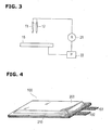
- FIG. 3 is a circuit diagram showing an electric circuit of this conductivity inspection apparatus 1.
- the two needles 11 and 12 are connected in parallel to one end side (first end side) of the ammeter 21.
- the other end side (second end side) of the ammeter 21 is connected to one terminal of a power supply 22.
- the other end side (second end side) of the power supply 22 is connected to the stage 15 (or the conductive pad on the stage). This circuit becomes the inspection means.
- the power supply 22 may be a direct current power supply, and an alternating current power supply.
- the ammeter 21 is used in accordance with the power supply 22.
- the direct current power supply the ammeter for the direct current is used.
- the alternating current power supply the ammeter for the alternating current is used.
- the electric voltage of the power supply 22 may be low voltage since the conductivity test is merely performed. For example, 1V-5V is sufficient.
- the voltage of about twice the electric voltage of the power generation element positioned in the inside sealed by the laminate may be applied. These voltages may be arbitrarily set in accordance with that object of the test. These are not specifically limited.
- FIG. 4 is a perspective view showing an outside of the battery which is sealed by the laminate.
- the laminate film has a stacked (laminated) film structure in which the metal foil (for example, aluminum foil) is sandwiched between the resin films. Then, the battery 10 which is covered with (sealed by) the laminate film is entirely covered with the laminate film 200.
- the battery 100 has the power generation element disposed inside the battery 100. In the battery shown in the drawings, two tabs which are electrode terminals of the battery are pulled out from one side (a positive electrode tab 101 and a negative electrode tab 102 are pulled out.
- the laminate film 200 is bonded and sealed at the periphery of the laminate film 200 by the heat seal and the adhesive.
- FIG. 5 is an enlarged sectional view of an edge portion of the laminate film.
- the laminated film is (has) total 6 layers of a first resin film 251, a first aluminum foil 252, a second resin film 253, a third resin film 261, a second aluminum foil 262, and a fourth resin film 263.
- FIGS. 6 are illustrative views for illustrating the operation of the conductivity inspection apparatus 1.
- FIG. 6(a) is a schematic front view before the needle insertion in a state where the battery is mounted on the stage.
- FIG. 6(b) is a schematic front view after the needle insertion.
- FIG. 7 is a plan view showing the needle insertion position of the battery.
- the battery which is an inspected object is mounted on the stage 15.
- the battery is mounted on the stage 15 so that the needles 11 and 12 are inserted in portions 11a and 12a of the edge portion 210 of the battery which are represented by two dot chain circles, and so that the elastic pad 16 (a two dot chain line in FIG. 7 ) is positioned at positions of the tabs 101 and 102. That is, the positions of the needles 11 and 12 and the elastic pad 16 are disposed in accordance with the configuration of the battery which is the inspected object.
- the elastic pad 16 presses the tabs 101 and 102, so that it is possible to concurrently attain the conductions of both the stage 15 or the conductive pad, and the positive electrode tab 101 and the negative electrode tab 102.
- the needles 11 and 12 with the support portion 13 are moved in the downward direction by actuating the air cylinder 14. With this, the needles 11 and 12 are inserted in the edge portion 210 of the laminate film. At this time, the two needles 11 and 12 are inserted in the edge portion 210 of the laminate film. Moreover, at the same time, the elastic pad 16 presses the tabs of the battery against the stage 15.
- the value of the ammeter 21 is read. If the power generation element within the battery and the aluminum foil 252 and/or 262 of the laminate film 200 are conductive with each other, the current flows, and it is sensed by the ammeter 21.
- the product is good if it is confirmed by the ammeter 21 that the current does not flow.
- the product is good if it is confirmed by the ammeter 21 that the current flows.
- the conductive pad it is possible to inspect the conduction states between the respective positive electrode tab 101 and negative electrode tab 102, and the laminate film 200, by providing the conductive pads, respectively, to the positive electrode tab 101 and the negative electrode tab 102. In this case, the inspection is performed by switching the conductive pads provided to the positive electrode tab and the negative electrode tab while the needles 11 and 12 are inserted. With this, it is possible to check whether the laminate film 200 is connected to the positive electrode system connected to the positive electrode tab 101, or the negative electrode system connected to the negative electrode tab 102, in the internal power generation element.
- FIG. 8 is a sectional view showing an internal section of the edge portion 210 of the laminate film in which the two needles 11 and 12 are inserted.
- the resin film is dragged (pulled in) by the needles by inserting the needle, and the resin film may be wound around the needles.
- the thus-dragging is generated for the expansion and the contraction (elasticity) of the resin film which is the elastic member.
- the winding may be generated or be not generated, and the amount of the dragging are different.
- the first resin film 251 is largely dragged by the needle 11.
- the needle 11 and the first aluminum foil 252 are not contacted with each other.
- the resin film is not largely dragged by the needle 12. Accordingly, the needle 12 and the first aluminum foil 252 are contacted with each other.
- FIG. 8 shows one example of the contact failure (poor contact) of the needle and the aluminum foil. This contact failure is not necessarily generated in this way. The contact failure between the needle and the aluminum foil may be generated in the various portions.
- the first embodiment described above attains following effects.
- the two needles 11 and 12 are inserted in parallel. Accordingly, even if one of the two needles does not contact on the aluminum foil due to the dragging, it is possible to inspect the conductive state if the other needle is effectively operated. Consequently, it is possible to decrease the generation of the inspection failure relative to a case where the inspection is performed by the one needle, and to improve the reliability of the inspection.
- the needles 11 and 12 are inserted in the edge portion 210 in which the laminate film 200 is bonded. Accordingly, it is possible to perform the conduction inspection without providing the influence to the inside of the produced battery.
- the stage 15 or the conductive pad is contacted on the tab 101 or 102 of the battery, so that this serves as the conductive terminal for attaining the electrical conduction with the internal power generation element. Accordingly, the electric circuit for the inspection is constituted merely by mounting the battery 100 on the stage 15. There are no trouble of mounting the clip to the tabs 101 and 102 of the battery as the operation (actuation) for the inspection. It is possible to readily perform the inspection process.
- FIG. 9 is a schematic view for illustrating the conductivity inspection apparatus of the battery which is covered with the laminate film (outer covering film) in a second embodiment.
- the conductivity inspection apparatus 2 is an apparatus in which a structure in which needles 31 and 32 are inserted from below is added to the structure in which the needles 11 and 12 are inserted from above in the first embodiment. That is, in a case where an upper side of the battery is a first surface and the lower side of the battery is a second surface, the needles 11 and 12, and 31 and 32 are inserted, respectively, from the first surface side, and the second surface side which is opposite to the first surface.
- the support portion 13 is provided with a pressing pad (retaining pad) 35 arranged to press (retain) so that the edge portion 210 of the laminate film 200 is not moved apart when the needles 31 and 32 are inserted from below at portions near the upper two needles 11 and 12.
- the stage 15 is provided with holes 37 through which the needles 31 and 32 pass so that the needles 31 and 32 from below are inserted in the laminate film.
- the pressing pad 35 is provided with holes 38 so that the needles 31 and 32 from below are not contacted.
- These holes 37 and 38 may be a size so as not to contact on the needles 31 and 32, and so as to prevent the laminate film from deforming and moving apart, like the hole 17 provided in the stage 15 in the first embodiment.
- sponge, rubber, other elastic resin and so on which has the insulation property and an elasticity are used for the pressing pad 35.
- Other structures are identical to those of the first embodiment. Accordingly, the explanations are omitted.
- FIG. 10 is an electric circuit diagram of the second embodiment. As shown in the drawing, four needles 11 and 12, and 31 and 32 are connected to the ammeter 21 in the parallel manner. The other circuit configuration is identical to that of the first embodiment. Accordingly, the explanation is omitted.
- FIG. 11 is a plan view showing positions of the battery in which the needles are inserted in the second embodiment.
- the needles 11 and 12 from above are inserted at positions shown by two dot chain line circles 11a and 12a of the edge portion 210 of the laminate film.
- the needles 31 and 32 from below are inserted at positions shown by two dot chain line circles 31a and 32a of the edge portion 210 of the laminate film.
- the elastic pad 16 (a two dot chain line in FIG. 11 ) is set to the position of the tabs 101 and 102, like the first embodiment.
- the upper needles 11 and 12 are moved in the downward direction so as to be inserted in the edge portion 210 of the laminate film 200.
- the pressing member 35 is abutted on the edge portion 210 of the laminate film 200.
- the needles 31 and 32 are also moved from below in the upward direction. With this, at least one of the four needles 11, 12, 31, and 32 is contacted on the aluminum foil of the laminate film 200.
- FIG. 12 is a sectional view showing an internal section of the edge portion of the laminate film in which the four needles 11, 12, 31, 32 are inserted.
- the resin film when the needles are inserted, the resin film may be pulled in (dragged) by the needles by inserting the needles, and the resin film may be wound around the needles. In particular, this failure may be generated with respect to the aluminum foil on the side farther from the surface in which the needle is inserted.
- two layer resin films 253 and 261 are disposed on the second aluminum foil 262 which is positioned at the farther position when it is viewed from direction in which the needles 11 and 12 are inserted (from the upward direction of the drawing). Accordingly, when the needles 11 and 12 are inserted from above, it is easy to be wound by the needles 11 and 12 since the two layer resin films are disposed on the second aluminum foil 262. It is identical in a case of the needles 31 and 32.
- the adhesion layer (not shown) may be further disposed between the resin films 253 and 261. In this case, the adhesion may be also wound.
- the needles 31 and 32 are also inserted from below.
- the needles 31 and 32 are unlikely to wind the second aluminum foil 262 in which the needles 11 and 12 from above are easy to generate the contact failure (poor contact), since there is only one layer of the fourth resin film 263 with respect to the needles 31 and 32. Consequently, even when the needles 11 and 12 from above generate the contact failure with the second aluminum foil 262, the needles 31 and 32 from below are unlikely to generate the contact failure (poor contact) with the second aluminum foil 262. Therefore, the reliability of the conduction inspection is improved. It is identical in a case of the needles 31 and 32 from below. The needles 31 and 32 from below are easy to generate the contact failure with respect to the first aluminum foil 252. However, the needles 11 and 12 from above is unlikely to generate the contact failure with respect to the first aluminum foil 252. Accordingly, the reliability of the conductive inspection is improved.
- the two needles 11 and 12, and the two needles 31 and 32 are inserted, respectively, from the both surface sides (the upper side and the lower side in the drawings) of the battery which is covered with the laminate film 200.
- a position (layer) at which the resin is easy to be wound are different in accordance with the direction in which the needles 11 and 12, and 31 and 32 are inserted. Accordingly, the inserted needles 11 and 12, and 31 and 32 maintain the contact with the aluminum foil on the side on which the resin film is unlikely to be wound. Accordingly, it is possible to further improve the reliability of the inspection.
- the needle is inserted at the edge portion 210, similarly to the first embodiment. Accordingly, the produced battery is not influenced. Moreover, the identical effects identical to those of the first embodiment are attained.
- the present invention is not limited to these embodiments.
- the number of the needles 11 and 12 which are inserted from the one side is not limited to two. This number may be three or four.
- the product has many holes. This is not preferable. Accordingly, in the case of inserting from the one surface (the first embodiment), and in the case of inserting from the both surfaces (the second embodiment), it is preferable that the total number of the holes is within about twelve (described later).
- the two needles 11 and 12 are inserted near each other in the edge portion 210.
- the needles 11 and 12 may be apart from each other.
- two needles are inserted, respectively, at sides on which the tabs do not protrude (three sides in the example of FIG. 4 ), so that total six needles are inserted.
- two needles are inserted from one side side. By summing the three sides, the number is the total twelve needles.
- the apparatus in a case where the needles are inserted from the both surfaces of the battery like the second embodiment, it is optional to use the apparatus according to the first embodiment, to inspect by inserting the needles 11 and 12 from the one side surface of the battery, and to inspect by inserting the needles 11 and 12 by turning over the same battery.
- the structure of the apparatus is simplified, and it is possible to attain the effects identical to those of the inspection in which the needles are inserted from the both side surfaces like the second embodiment.
- the battery which is the inspected object is not limited to the battery shown in FIG. 4 .
- the battery may have any shape as long as the battery (it) is covered with the laminate film 200.
- the battery may be the battery in which the positive electrode tab 101 is pulled out from the one side side, and the negative electrode tab 102 is pulled out from the side which is opposite to that side.
- the positive electrode tab 101 and the negative electrode tab 102 are conducted, respectively, to the stage 15 or the conductive pad on the stage 15.
- the structure of the laminate film 200 is a structure in which the resin film sandwiches the metal foil other than the aluminum foil.
- the total number of the resin film and the total number of the metal foil are not limited.
- the one needle may be inserted from the one surface sides, so that the total two needles may be inserted. Even in this structure, at least one needle of the two inserted needles is contacted on the internal aluminum foil. In particular, the reliability of the inspection is improved merely by inserting one needle from the both sides relative to a case of inserting the two needles from the same surface, since the readiness of the wounding of the resin are different in accordance with the inserting direction as described above.
- the needles are inserted into the laminate film to penetrate through. However, it is sufficient that the needles reach the metal foil within the laminate film (the outer covering film). It is unnecessary to penetrate through. When the needle does not penetrate through, the hole provided to the stage is not needed.
- the battery which is covered with the laminate film is shown as the structural member which is covered with the laminate film in which the metal foil is sandwiched by the resin film.
- the inspected object of the present invention is not limited to this. That is, as long as it is the structural member which is covered with the laminate film, it is possible to use for the conduction inspection between the internal member within that, and the metal foil constituting the laminate film.
- the present invention can employ a structure other than a structure explained herein is added, or a structure in which a part does not exist can be employed as long as it includes a structure defined in claims.
- the present invention can includes various configurations.
Landscapes
- Physics & Mathematics (AREA)
- General Physics & Mathematics (AREA)
- General Chemical & Material Sciences (AREA)
- Manufacturing & Machinery (AREA)
- Chemical & Material Sciences (AREA)
- Chemical Kinetics & Catalysis (AREA)
- Electrochemistry (AREA)
- Engineering & Computer Science (AREA)
- Geometry (AREA)
- Connection Of Batteries Or Terminals (AREA)
- Secondary Cells (AREA)
- Battery Mounting, Suspending (AREA)
- Sealing Battery Cases Or Jackets (AREA)
- Testing Of Short-Circuits, Discontinuities, Leakage, Or Incorrect Line Connections (AREA)
- Tests Of Electric Status Of Batteries (AREA)
- Primary Cells (AREA)
Abstract
Description
- This invention relates to a conductivity inspection apparatus and a method thereof, and more specifically to a conductivity inspection apparatus and a method thereof which are configured to inspect a conductive state of a structural member covered by a film in which a metal foil is sandwiched between resin films.
- In recent years, a laminate film (also referred to as a laminate sheet) is used as an outer covering member for covering a power generation element of a battery for decreasing a weight of the battery, and decreasing a thickness of the battery. The laminate film has, for example, a structure in which an aluminum foil is stacked between a resin film and a resin film.
- As a conduction (continuity) test method between this laminate film and the internal power generation element, there is a method of inserting a metal needle on a surface of the outer member of the laminate film, and measuring a resistance between this needle and a lead electrode extending from the power generation element (patent document 1).
- In a normal laminate-packed battery, the internal power generation element and the laminate film are insulated so as not to leak the current to the laminate film which is the outer covering member (package) (cf. background art of the patent document 1). By applying the conventional art, it is possible to test the insulating state between the power generation element and the laminate film by inserting the needle from the surface of the laminate film, and measuring the resistance between this needle and the lead electrode extending from the power generation element.
- However, the laminate film has a structure in which the aluminum foil is sandwiched between the two resin films. Accordingly, when the needle is inserted from above on the surface of the laminate film, that is, the resin film, the needle may drag and wound the resin. In this case, the resin is wound around the needle, so that the needle and the aluminum foil are not contacted with each other. Consequently, it is not understand whether or not the power generation element and the aluminum foil of the laminate film are conducted with each other. The reliability of the conduction test is decreased. That is, even when the power generation element and the aluminum foil of the laminate film are conducted (short-circuited), the test result represents that there is no conduction.
- Patent Document 1:
WO01/008248 - It is, therefore, an object of the present invention to provide a conductivity inspection apparatus and a method thereof which are configured to inspect an electrical conductive state of a structural member which is covered with an outer covering film in which a metal foil is sandwiched by resin films.
- A conductivity inspection apparatus according to the present invention comprises: at least two needles inserted from a surface of an outer covering film of a structural member covered with the outer covering film having a stacked film configuration in which a metal foil is sandwiched by resin films, to reach the metal foil; and an inspection means configured to inspect a conduction state between a member within the structural member, and the two needles.
- A conductivity inspection method comprises: inserting at least two needles from a surface of an outer covering film of a structural member covered with the outer covering film having a stacked film configuration in which a metal foil is sandwiched by resin films, to reach the metal foil; and inspecting a conduction state between a member within the structural member, and the two needles.
- By the present invention, at least two needles are inserted. Accordingly, when one of the at least two needles is contacted on the metal foil, it is possible to inspect the conduction state. Consequently, it is possible to decrease the generation of the inspection failure, and to improve the reliability of the inspection, relative to a case in which the inspection is performed by one needle.
-
-
FIG. 1 is a schematic view for illustrating a conductivity inspection apparatus of a battery which is covered with a laminate film in a first embodiment. -
FIG. 2 is a plan view showing a battery mounting surface of a stage. -
FIG. 3 is a circuit diagram showing an electric circuit of the conductivity inspection apparatus. -
FIG. 4 is a perspective view showing an outside of the battery which is sealed by a laminate. -
FIG. 5 is an enlarged sectional view of a portion of an edge of a laminate film. -
FIGS. 6 are illustrative views for illustrating an operation of the conductivity inspection apparatus. -
FIG. 7 is a plan view showing a needle insertion position of the battery in the first embodiment. -
FIG. 8 is a sectional view showing an inner section of the portion of the edge of the laminate film in which two needles are inserted. -
FIG. 9 is a schematic view for illustrating a conductivity inspection apparatus of a battery covered with a laminate film in a second embodiment. -
FIG. 10 is an electric circuit diagram in the second embodiment. -
FIG. 11 is a plan view showing a needle insertion position of the battery in the second embodiment. -
FIG. 12 is a sectional view showing an inner section of a portion of an edge of the laminate film in which four needles are inserted. - Hereinafter, embodiments of the present invention are illustrated with reference to the drawings. Besides, the same element has the same symbol in the explanation of the drawings. Repetitive explanations are omitted. Moreover, sizes and ratios of members in the drawings are exaggerated for the explanation. These sizes and ratios are different from actual sizes and actual ratios.
-
FIG. 1 is a schematic view for illustrating a conductivity inspection apparatus of a battery covered with a laminate film (an outer covering film) in a first embodiment. - This
conductivity inspection apparatus 1 includes twoconductive needles needles air cylinder 14 arranged to move thesupport portion 13 in upward and downward directions, and astage 15 holding the battery at a predetermined position. Moreover, the support portion (section) 13 is provided with anelastic pad 16 which is arranged to press tabs of the battery against thestage 15, at a position of the tabs of the battery which is mounted on thestage 15, as described below. - Two
needles - The two
needles support portion 13 through insulators (insulations) (not shown). In this case, each of the insulators is a rubber or a resin. However, the insulators are not specifically limited to these. Theneedles support portion 13 is not electrically short-circuited with theneedles elastic pad 16 is also mounted. - The
air cylinder 14 is arranged to move thesupport portion 13 apart from and toward thestage 15. That is, inFIG. 1 , theair cylinder 14 moves thesupport portion 13 in the upward and downward directions. Thesupport portion 13 integrally supports the twoneedles needles elastic pad 16 is moved together. Besides, a portion of theair cylinder 14 which is not operated is fixed to 19 such as a support (fulcrum) and a frame (not shown). - In place of the
air cylinder 14, it is possible to use an oil cylinder, a mechanism of a combination of a motor and a gear, other actuators, and so on. - The
stage 15 is supported by a base (seating) 18.FIG. 2 is a plan view showing a battery mounting surface of thestage 15. As shown in the drawing, holes 17 are opened in thestage 15 at positions corresponding to the twoneedles holes 17 can have any size as long as theneedles stage 15 when theneedles holes 17 can be polygon, in addition to a circular shape shown in the drawing. The shape of thehole 17 is not limited. However, in a case in which the hole is too large, it is not possible to support the laminate film when theneedles needles needles circular hole 17, about 2-5 mm is sufficient for the size. Needless to say, the size of thehole 17 can be larger than this, for example, about 1 cm, in consideration of the safety so as not to contact on thestage 15. However, in a case where the size of thehole 17 is too large, the laminate film is distorted by the pressure when theneedles needles hole 17 has the adequate size as described above. - Moreover, at least a portion of the stage surface at a position of the tabs of the battery mounted on the stage is conductive. With this, the electric conduction between the battery tabs and it is attained. Besides, the insulation sheet (not shown) is sandwiched between the
stage 15 and thebase 18, orbase 18 and the floor surface, so as to attain the insulation state. - In a case where the only portion of the
stage 15 at the position of the battery tabs is set to have the conductive property, the conductive pad (not shown) is provided to that portion. A portion between the conductive pad and thestage 15 may be set to have the insulation property so as to keep the insulation property between the entire of thestage 15 and the battery (the battery tabs). - The thus-constructed
stage 15 and the conductive pad become a conductive terminal for attaining an electric conductivity (electric continuity) with an inside of the structure which is covered with the laminate film. - The
elastic pad 16 is arranged to press the mounted battery tabs from above for improving the conductivity between the tabs of the battery mounted on thestage 15, and the stage 15 (or the conductive pad). Theelastic pad 16 may be, for example, a sponge, a rubber, a felt, other elastic resins and so on. Thiselastic pad 16 is arranged to press the battery tabs toward thestage 15 at the same time when thesupport portion 13 is moved in the downward direction and theneedles - . Besides, in a case where this
elastic pad 16 is provided, a portion between thestage 15 and theelastic pad 16 is set to have the insulation property, and the surface of theelastic pad 16 is set to have the conductive property. In this way, the conductivity may be attained by a portion between this conductiveelastic pad 16 and the battery tabs. - Moreover, when other conductive means (for example, conductive clip and so on) are provided in addition, the
elastic pad 16 needs not to be provided. Moreover, in a case in which the other conductive means is provided, it is not necessary that thestage 15 and a part of thestage 15 is set to have the conductivity. -
FIG. 3 is a circuit diagram showing an electric circuit of thisconductivity inspection apparatus 1. - As shown in the drawing, the two
needles ammeter 21. The other end side (second end side) of theammeter 21 is connected to one terminal of apower supply 22. The other end side (second end side) of thepower supply 22 is connected to the stage 15 (or the conductive pad on the stage). This circuit becomes the inspection means. - Besides, it is optional to provide a switch in the circuit, if necessary. Moreover, the
power supply 22 may be a direct current power supply, and an alternating current power supply. However, theammeter 21 is used in accordance with thepower supply 22. In case of the direct current power supply, the ammeter for the direct current is used. In case of the alternating current power supply, the ammeter for the alternating current is used. The electric voltage of thepower supply 22 may be low voltage since the conductivity test is merely performed. For example, 1V-5V is sufficient. However, in a case where electric breakdown withstand voltage of the laminate film is measured, the voltage of about twice the electric voltage of the power generation element positioned in the inside sealed by the laminate may be applied. These voltages may be arbitrarily set in accordance with that object of the test. These are not specifically limited. - Moreover, in this circuit diagram, the
power source 22 and theammeter 21 are shown. That is, this is the configuration of the resistance measuring circuit. Accordingly, this is the same with a case where the resistance measuring device is used between the twoneedles - Operations of the thus-constructed
conductivity inspection apparatus 1 are illustrated. - First, the battery which is a tested object, and which is sealed by the laminate is briefly illustrated.
-
FIG. 4 is a perspective view showing an outside of the battery which is sealed by the laminate. As one knows, the laminate film has a stacked (laminated) film structure in which the metal foil (for example, aluminum foil) is sandwiched between the resin films. Then, the battery 10 which is covered with (sealed by) the laminate film is entirely covered with thelaminate film 200. Thebattery 100 has the power generation element disposed inside thebattery 100. In the battery shown in the drawings, two tabs which are electrode terminals of the battery are pulled out from one side (apositive electrode tab 101 and anegative electrode tab 102 are pulled out. Thelaminate film 200 is bonded and sealed at the periphery of thelaminate film 200 by the heat seal and the adhesive. -
FIG. 5 is an enlarged sectional view of an edge portion of the laminate film. As shown in the drawing, in theedge portion 210 which is bonded, twolaminate films 200 are superimposed. Accordingly, in a case where only this portion is viewed, the laminated film is (has) total 6 layers of afirst resin film 251, afirst aluminum foil 252, a second resin film 253, athird resin film 261, asecond aluminum foil 262, and afourth resin film 263. - The operation of the
conductivity inspection apparatus 1 is illustrated.FIGS. 6 are illustrative views for illustrating the operation of theconductivity inspection apparatus 1.FIG. 6(a) is a schematic front view before the needle insertion in a state where the battery is mounted on the stage.FIG. 6(b) is a schematic front view after the needle insertion.FIG. 7 is a plan view showing the needle insertion position of the battery. - First, as shown in
FIG. 6(a) , the battery which is an inspected object is mounted on thestage 15. As shown inFIG. 7 , the battery is mounted on thestage 15 so that theneedles portions edge portion 210 of the battery which are represented by two dot chain circles, and so that the elastic pad 16 (a two dot chain line inFIG. 7 ) is positioned at positions of thetabs needles elastic pad 16 are disposed in accordance with the configuration of the battery which is the inspected object. Theelastic pad 16 presses thetabs stage 15 or the conductive pad, and thepositive electrode tab 101 and thenegative electrode tab 102. - Then, as shown in
FIG. 6(b) , theneedles support portion 13 are moved in the downward direction by actuating theair cylinder 14. With this, theneedles edge portion 210 of the laminate film. At this time, the twoneedles edge portion 210 of the laminate film. Moreover, at the same time, theelastic pad 16 presses the tabs of the battery against thestage 15. - Then, the value of the
ammeter 21 is read. If the power generation element within the battery and thealuminum foil 252 and/or 262 of thelaminate film 200 are conductive with each other, the current flows, and it is sensed by theammeter 21. - With this, it is possible to perform the inspection of the conduction between the power generation element within the battery and the aluminum foils 252 and/or 262. Besides, in a case where the short-circuit is defined as the failure, the product is good if it is confirmed by the
ammeter 21 that the current does not flow. On the other hand, in a case where the aluminum foil is the insulating shield, the product is good if it is confirmed by theammeter 21 that the current flows. - Besides, in case of using the conductive pad, it is possible to inspect the conduction states between the respective
positive electrode tab 101 andnegative electrode tab 102, and thelaminate film 200, by providing the conductive pads, respectively, to thepositive electrode tab 101 and thenegative electrode tab 102. In this case, the inspection is performed by switching the conductive pads provided to the positive electrode tab and the negative electrode tab while theneedles laminate film 200 is connected to the positive electrode system connected to thepositive electrode tab 101, or the negative electrode system connected to thenegative electrode tab 102, in the internal power generation element. - In this case, a state of the
edge portion 210 of the laminate film in which theneedles FIG. 8 is a sectional view showing an internal section of theedge portion 210 of the laminate film in which the twoneedles - As shown in the drawings, in the
edge portion 210 of the laminate film, when the needles are inserted, the resin film is dragged (pulled in) by the needles by inserting the needle, and the resin film may be wound around the needles. The thus-dragging is generated for the expansion and the contraction (elasticity) of the resin film which is the elastic member. Moreover, in accordance with the various causes of the minute difference of the thickness of the resin film, and the difference of the shape of the surface, the winding may be generated or be not generated, and the amount of the dragging are different. In the state shown in the drawing, thefirst resin film 251 is largely dragged by theneedle 11. In this case, theneedle 11 and thefirst aluminum foil 252 are not contacted with each other. On the other hand, the resin film is not largely dragged by theneedle 12. Accordingly, theneedle 12 and thefirst aluminum foil 252 are contacted with each other. - In this state, if the power generation element and the
aluminum foil 252 are short-circuited, it is not possible to judge the short-circuit by this since theneedle 11 and thealuminum foil 252 are not contacted with each other. However, in the first embodiment, anotherneedle 12 is connected in parallel. Thisneedle 12 does not drag thefirst resin film 251. Accordingly, it is possible to sense the short-circuit since theneedle 12 is contacted with thealuminum foil 252. - Besides,
FIG. 8 shows one example of the contact failure (poor contact) of the needle and the aluminum foil. This contact failure is not necessarily generated in this way. The contact failure between the needle and the aluminum foil may be generated in the various portions. - The first embodiment described above attains following effects.
- In case of the inspection performed by the only one needle, if that one needle drags the resin film and the one needle does not contact on the aluminum foil, it may not be possible to sense the conduction state (the short-circuit and so on) between the
laminate film 200 and the internal power generation element. On the other hand, in the first embodiment, the twoneedles - Moreover, it is possible to perform the inspection if the other of the
needles needles needles - Furthermore, in the first embodiment, the
needles edge portion 210 in which thelaminate film 200 is bonded. Accordingly, it is possible to perform the conduction inspection without providing the influence to the inside of the produced battery. - Moreover, the
stage 15 or the conductive pad is contacted on thetab battery 100 on thestage 15. There are no trouble of mounting the clip to thetabs -
FIG. 9 is a schematic view for illustrating the conductivity inspection apparatus of the battery which is covered with the laminate film (outer covering film) in a second embodiment. - The
conductivity inspection apparatus 2 according to the second embodiment is an apparatus in which a structure in which needles 31 and 32 are inserted from below is added to the structure in which theneedles needles - Accordingly, in the second embodiment, there are provided two
needles stage 15, a lower support portion 33 which supports theseneedles lower air cylinder 34 which moves the lower support portion 33 toward and apart from thestage 15. Furthermore, thesupport portion 13 is provided with a pressing pad (retaining pad) 35 arranged to press (retain) so that theedge portion 210 of thelaminate film 200 is not moved apart when theneedles needles stage 15 is provided withholes 37 through which theneedles needles pressing pad 35 is provided withholes 38 so that theneedles holes needles hole 17 provided in thestage 15 in the first embodiment. Moreover, sponge, rubber, other elastic resin and so on which has the insulation property and an elasticity are used for thepressing pad 35. Other structures are identical to those of the first embodiment. Accordingly, the explanations are omitted. -
FIG. 10 is an electric circuit diagram of the second embodiment. As shown in the drawing, fourneedles ammeter 21 in the parallel manner. The other circuit configuration is identical to that of the first embodiment. Accordingly, the explanation is omitted. -
FIG. 11 is a plan view showing positions of the battery in which the needles are inserted in the second embodiment. - As shown in the drawings, the
needles edge portion 210 of the laminate film. Moreover, theneedles edge portion 210 of the laminate film. The elastic pad 16 (a two dot chain line inFIG. 11 ) is set to the position of thetabs - In the operation of the
conductivity inspection apparatus 1 in the second embodiment, first, theupper needles edge portion 210 of thelaminate film 200. At this time, the pressingmember 35 is abutted on theedge portion 210 of thelaminate film 200. Accordingly, theneedles needles laminate film 200. -
FIG. 12 is a sectional view showing an internal section of the edge portion of the laminate film in which the fourneedles - As shown in the drawing, when the needles are inserted, the resin film may be pulled in (dragged) by the needles by inserting the needles, and the resin film may be wound around the needles. In particular, this failure may be generated with respect to the aluminum foil on the side farther from the surface in which the needle is inserted. As shown in the drawing, two
layer resin films 253 and 261 are disposed on thesecond aluminum foil 262 which is positioned at the farther position when it is viewed from direction in which theneedles needles needles second aluminum foil 262.
It is identical in a case of theneedles resin films 253 and 261. In this case, the adhesion may be also wound. - Accordingly, in the second embodiment, the
needles needles second aluminum foil 262 in which theneedles fourth resin film 263 with respect to theneedles needles second aluminum foil 262, theneedles second aluminum foil 262. Therefore, the reliability of the conduction inspection is improved. It is identical in a case of theneedles needles first aluminum foil 252. However, theneedles first aluminum foil 252. Accordingly, the reliability of the conductive inspection is improved. - The following effects are attained in the second embodiment.
- The two
needles needles laminate film 200. In theedge portion 210 of thelaminate film 200 having a structure in which the two layers are superimposed, a position (layer) at which the resin is easy to be wound are different in accordance with the direction in which theneedles - Moreover, the needle is inserted at the
edge portion 210, similarly to the first embodiment. Accordingly, the produced battery is not influenced. Moreover, the identical effects identical to those of the first embodiment are attained. - Hereinabove, the embodiments to which the present invention is applied are explained. However, the present invention is not limited to these embodiments. For example, the number of the
needles - Moreover, the two
needles edge portion 210. However, theneedles FIG. 4 ), so that total six needles are inserted. In a case where it is similarly performed from both the both surface sides, two needles are inserted from one side side. By summing the three sides, the number is the total twelve needles. - Moreover, in a case where the needles are inserted from the both surfaces of the battery like the second embodiment, it is optional to use the apparatus according to the first embodiment, to inspect by inserting the
needles needles - Furthermore, the battery which is the inspected object is not limited to the battery shown in
FIG. 4 . The battery may have any shape as long as the battery (it) is covered with thelaminate film 200. For example, unlikeFIG. 4 , the battery may be the battery in which thepositive electrode tab 101 is pulled out from the one side side, and thenegative electrode tab 102 is pulled out from the side which is opposite to that side. In this case, in the apparatus configuration, thepositive electrode tab 101 and thenegative electrode tab 102 are conducted, respectively, to thestage 15 or the conductive pad on thestage 15. - Moreover, it is possible to inspect as long as the structure of the
laminate film 200 is a structure in which the resin film sandwiches the metal foil other than the aluminum foil. Moreover, the total number of the resin film and the total number of the metal foil are not limited. - Moreover, in a case where the needles are inserted from the both surface sides of the battery like the second embodiment, the one needle may be inserted from the one surface sides, so that the total two needles may be inserted. Even in this structure, at least one needle of the two inserted needles is contacted on the internal aluminum foil. In particular, the reliability of the inspection is improved merely by inserting one needle from the both sides relative to a case of inserting the two needles from the same surface, since the readiness of the wounding of the resin are different in accordance with the inserting direction as described above.
- Moreover, the needles are inserted into the laminate film to penetrate through. However, it is sufficient that the needles reach the metal foil within the laminate film (the outer covering film). It is unnecessary to penetrate through. When the needle does not penetrate through, the hole provided to the stage is not needed.
- Moreover, in the embodiments, the battery which is covered with the laminate film is shown as the structural member which is covered with the laminate film in which the metal foil is sandwiched by the resin film. However, the inspected object of the present invention is not limited to this. That is, as long as it is the structural member which is covered with the laminate film, it is possible to use for the conduction inspection between the internal member within that, and the metal foil constituting the laminate film.
- The present invention can employ a structure other than a structure explained herein is added, or a structure in which a part does not exist can be employed as long as it includes a structure defined in claims. The present invention can includes various configurations.
Claims (8)
- A conductivity inspection apparatus comprising:at least two needles inserted from a surface of an outer covering film of a structural member covered with the outer covering film having a stacked film configuration in which a metal foil is sandwiched by resin films, to reach the metal foil; andan inspection means configured to inspect a conduction state between a member within the structural member, and the two needles.
- The conductivity inspection apparatus as claimed in Claim 1, wherein at least one of the two needles is inserted from a first surface side of the structural member; and at least one of the two needles is inserted from a second surface side of the structural member which is opposite to the first surface side.
- The conductivity inspection apparatus as claimed in Claim 1 or 2, wherein a position at which the needle is inserted is a portion at which the outer covering film is superimposed and bonded.
- The conductivity inspection apparatus as claimed in one of Claims 1 to 3, wherein the inspection means includes a conductive terminal for attaining the electrical conduction with the member inside the structural member.
- A conductivity inspection method comprising:inserting at least two needles from a surface of an outer covering film of a structural member covered with the outer covering film having a stacked film configuration in which a metal foil is sandwiched by resin films, to reach the metal foil; andinspecting a conduction state between a member within the structural member, and the two needles.
- The conductivity inspection method as claimed in Claim 5, wherein at least one of the needles is inserted from a first surface side of the structural member; and at least one of the needles is inserted from a second surface side of the structural member which is opposite to the first surface side.
- The conductivity inspection method as claimed in Claim 5 or 6, wherein a position at which the needle is inserted is a portion at which the outer covering film is superimposed and bonded.
- The conductivity inspection method as claimed in one of Claims 5 to 7, wherein the inspection means includes a conductive terminal for attaining the electrical conduction with the member inside the structural member.
Applications Claiming Priority (2)
| Application Number | Priority Date | Filing Date | Title |
|---|---|---|---|
| JP2012028344A JP6088145B2 (en) | 2012-02-13 | 2012-02-13 | Battery manufacturing method and conductivity inspection apparatus |
| PCT/JP2013/052432 WO2013121902A1 (en) | 2012-02-13 | 2013-02-04 | Conductivity inspection apparatus and conductivity inspection method |
Publications (3)
| Publication Number | Publication Date |
|---|---|
| EP2816362A1 true EP2816362A1 (en) | 2014-12-24 |
| EP2816362A4 EP2816362A4 (en) | 2015-10-21 |
| EP2816362B1 EP2816362B1 (en) | 2017-11-15 |
Family
ID=48984016
Family Applications (1)
| Application Number | Title | Priority Date | Filing Date |
|---|---|---|---|
| EP13749918.2A Active EP2816362B1 (en) | 2012-02-13 | 2013-02-04 | Conductivity inspection apparatus |
Country Status (6)
| Country | Link |
|---|---|
| US (1) | US9459284B2 (en) |
| EP (1) | EP2816362B1 (en) |
| JP (1) | JP6088145B2 (en) |
| KR (1) | KR20140128985A (en) |
| CN (1) | CN104115015B (en) |
| WO (1) | WO2013121902A1 (en) |
Families Citing this family (8)
| Publication number | Priority date | Publication date | Assignee | Title |
|---|---|---|---|---|
| US10151789B2 (en) | 2015-02-09 | 2018-12-11 | Acculogic Corporation | Method and device for testing the connections of batteries |
| JP6900716B2 (en) * | 2017-03-14 | 2021-07-07 | 日本電気株式会社 | Battery internal short circuit test method and internal short circuit test equipment |
| JP7062891B2 (en) * | 2017-07-12 | 2022-05-09 | 日本電気株式会社 | Battery internal short circuit test method and internal short circuit test equipment |
| JP6791104B2 (en) * | 2017-11-29 | 2020-11-25 | トヨタ自動車株式会社 | Evaluation method of power storage device, manufacturing method of power storage device, and test system |
| JP6969997B2 (en) * | 2017-12-08 | 2021-11-24 | 株式会社エンビジョンAescジャパン | Battery manufacturing method and battery conductivity inspection device |
| CN108226801A (en) * | 2018-01-12 | 2018-06-29 | 深圳市欧盛自动化有限公司 | Soft-package battery side short-circuit voltage test method, device and instrument |
| CN110398657A (en) * | 2019-08-20 | 2019-11-01 | 深圳市蓝眼科技有限公司 | Measured value needle and measuring mechanism |
| KR102932146B1 (en) | 2021-08-25 | 2026-02-27 | 주식회사 엘지에너지솔루션 | Battery Module Inspection Device Capable of Adjusting Position of Coupling Part |
Family Cites Families (14)
| Publication number | Priority date | Publication date | Assignee | Title |
|---|---|---|---|---|
| JPH07282841A (en) | 1994-04-05 | 1995-10-27 | Mitsubishi Chem Corp | Lithium ion secondary battery |
| EP1120846A4 (en) * | 1999-07-23 | 2005-03-30 | Mitsubishi Electric Corp | CELL AND CELL INSPECTION METHOD |
| JP3371869B2 (en) * | 1999-10-29 | 2003-01-27 | 日本電気株式会社 | High-speed test equipment for bare-chip LSI-mounted boards |
| JP4135335B2 (en) * | 2001-04-26 | 2008-08-20 | 株式会社ジーエス・ユアサコーポレーション | Insulation inspection method for sealed batteries |
| JP4030306B2 (en) * | 2001-12-27 | 2008-01-09 | 日本特殊陶業株式会社 | Battery manufacturing method |
| DE10220343B4 (en) * | 2002-05-07 | 2007-04-05 | Atg Test Systems Gmbh & Co. Kg Reicholzheim | Apparatus and method for testing printed circuit boards and probes |
| US6897668B1 (en) * | 2003-11-28 | 2005-05-24 | Premtek International Inc. | Double-faced detecting devices for an electronic substrate |
| JP4880879B2 (en) * | 2004-03-08 | 2012-02-22 | 株式会社東芝 | Non-aqueous electrolyte secondary battery inspection method and non-aqueous electrolyte secondary battery manufacturing method |
| CN101114003A (en) * | 2006-07-26 | 2008-01-30 | 深圳市邦凯电子有限公司 | Shorting or breaking circuit testing method of polyalcohol flexible packing |
| JP5254332B2 (en) * | 2007-07-19 | 2013-08-07 | エルジー・ケム・リミテッド | Large capacity battery pack |
| KR101180830B1 (en) * | 2008-10-13 | 2012-09-07 | 주식회사 엘지화학 | Apparatus and method for checking insulation of cell module assembly and probe for it |
| EP2485313B1 (en) | 2009-09-30 | 2021-11-24 | Dai Nippon Printing Co., Ltd. | Insulation failure inspecting apparatus, insulation failure inspecting method using same, and method for manufacturing electrochemical cell |
| JP2012028023A (en) * | 2010-07-20 | 2012-02-09 | Nissan Motor Co Ltd | Battery |
| JP5839986B2 (en) * | 2011-12-26 | 2016-01-06 | 日産自動車株式会社 | Inspection method and inspection system |
-
2012
- 2012-02-13 JP JP2012028344A patent/JP6088145B2/en active Active
-
2013
- 2013-02-04 US US14/378,047 patent/US9459284B2/en active Active
- 2013-02-04 CN CN201380009319.4A patent/CN104115015B/en active Active
- 2013-02-04 WO PCT/JP2013/052432 patent/WO2013121902A1/en not_active Ceased
- 2013-02-04 KR KR1020147021640A patent/KR20140128985A/en not_active Ceased
- 2013-02-04 EP EP13749918.2A patent/EP2816362B1/en active Active
Also Published As
| Publication number | Publication date |
|---|---|
| US9459284B2 (en) | 2016-10-04 |
| EP2816362B1 (en) | 2017-11-15 |
| JP6088145B2 (en) | 2017-03-01 |
| EP2816362A4 (en) | 2015-10-21 |
| JP2013164380A (en) | 2013-08-22 |
| CN104115015A (en) | 2014-10-22 |
| KR20140128985A (en) | 2014-11-06 |
| US20150022228A1 (en) | 2015-01-22 |
| WO2013121902A1 (en) | 2013-08-22 |
| CN104115015B (en) | 2017-10-10 |
Similar Documents
| Publication | Publication Date | Title |
|---|---|---|
| US9459284B2 (en) | Conductivity inspection apparatus and conductivity inspection method | |
| JPWO2014178236A1 (en) | Charge / discharge inspection apparatus and charge / discharge inspection method for thin secondary battery | |
| US20110254558A1 (en) | Testing system and method for testing a battery cell | |
| CN203479842U (en) | Lithium-battery high voltage test equipment and test clamp thereof | |
| CN111337844B (en) | Power battery module insulation and voltage resistance test assembly and test method | |
| JP2008251437A (en) | Power supply device and expansion detection method of electrochemical element | |
| CN110137155B (en) | Array substrate mother board | |
| JP5839986B2 (en) | Inspection method and inspection system | |
| JP2012174335A (en) | Lead member | |
| JP6154867B2 (en) | Inspection method and inspection system | |
| JP6738138B2 (en) | Rechargeable battery inspection device and rechargeable battery inspection method | |
| JP6573258B2 (en) | Rechargeable battery inspection device and rechargeable battery inspection method | |
| CN102121961B (en) | High voltage-resistant test device and high voltage-resistant test method adopting same | |
| CN102866268A (en) | Testing fixture | |
| CN203587741U (en) | High voltage resistance testing device | |
| CN210775593U (en) | Insulation test piece | |
| JP6969997B2 (en) | Battery manufacturing method and battery conductivity inspection device | |
| JP2002324572A (en) | Sealed battery insulation inspection apparatus and sealed battery insulation inspection method | |
| CN202421237U (en) | Short connection testing line | |
| CN207965035U (en) | A kind of insulation testing mechanism | |
| JP2018077119A (en) | Gas sensor | |
| JP2016012947A (en) | Polymer actuator element | |
| WO2009136721A3 (en) | A test socket and a fabrication method therefor | |
| CN105067982A (en) | Verification apparatus of solder point between lead wire and device | |
| JP2007309714A (en) | Line-to-line short-circuit inspection system |
Legal Events
| Date | Code | Title | Description |
|---|---|---|---|
| PUAI | Public reference made under article 153(3) epc to a published international application that has entered the european phase |
Free format text: ORIGINAL CODE: 0009012 |
|
| 17P | Request for examination filed |
Effective date: 20140807 |
|
| AK | Designated contracting states |
Kind code of ref document: A1 Designated state(s): AL AT BE BG CH CY CZ DE DK EE ES FI FR GB GR HR HU IE IS IT LI LT LU LV MC MK MT NL NO PL PT RO RS SE SI SK SM TR |
|
| AX | Request for extension of the european patent |
Extension state: BA ME |
|
| DAX | Request for extension of the european patent (deleted) | ||
| RA4 | Supplementary search report drawn up and despatched (corrected) |
Effective date: 20150923 |
|
| RIC1 | Information provided on ipc code assigned before grant |
Ipc: H01M 10/04 20060101ALI20150917BHEP Ipc: G01R 31/02 20060101AFI20150917BHEP Ipc: G01R 31/36 20060101ALI20150917BHEP Ipc: G01R 1/067 20060101ALI20150917BHEP Ipc: H01M 10/48 20060101ALI20150917BHEP |
|
| GRAP | Despatch of communication of intention to grant a patent |
Free format text: ORIGINAL CODE: EPIDOSNIGR1 |
|
| INTG | Intention to grant announced |
Effective date: 20170726 |
|
| GRAS | Grant fee paid |
Free format text: ORIGINAL CODE: EPIDOSNIGR3 |
|
| GRAA | (expected) grant |
Free format text: ORIGINAL CODE: 0009210 |
|
| AK | Designated contracting states |
Kind code of ref document: B1 Designated state(s): AL AT BE BG CH CY CZ DE DK EE ES FI FR GB GR HR HU IE IS IT LI LT LU LV MC MK MT NL NO PL PT RO RS SE SI SK SM TR |
|
| REG | Reference to a national code |
Ref country code: CH Ref legal event code: EP Ref country code: GB Ref legal event code: FG4D Ref country code: AT Ref legal event code: REF Ref document number: 946804 Country of ref document: AT Kind code of ref document: T Effective date: 20171115 |
|
| REG | Reference to a national code |
Ref country code: IE Ref legal event code: FG4D |
|
| REG | Reference to a national code |
Ref country code: DE Ref legal event code: R096 Ref document number: 602013029490 Country of ref document: DE |
|
| REG | Reference to a national code |
Ref country code: FR Ref legal event code: PLFP Year of fee payment: 6 |
|
| REG | Reference to a national code |
Ref country code: NL Ref legal event code: MP Effective date: 20171115 |
|
| REG | Reference to a national code |
Ref country code: LT Ref legal event code: MG4D |
|
| REG | Reference to a national code |
Ref country code: AT Ref legal event code: MK05 Ref document number: 946804 Country of ref document: AT Kind code of ref document: T Effective date: 20171115 |
|
| PG25 | Lapsed in a contracting state [announced via postgrant information from national office to epo] |
Ref country code: FI Free format text: LAPSE BECAUSE OF FAILURE TO SUBMIT A TRANSLATION OF THE DESCRIPTION OR TO PAY THE FEE WITHIN THE PRESCRIBED TIME-LIMIT Effective date: 20171115 Ref country code: ES Free format text: LAPSE BECAUSE OF FAILURE TO SUBMIT A TRANSLATION OF THE DESCRIPTION OR TO PAY THE FEE WITHIN THE PRESCRIBED TIME-LIMIT Effective date: 20171115 Ref country code: NO Free format text: LAPSE BECAUSE OF FAILURE TO SUBMIT A TRANSLATION OF THE DESCRIPTION OR TO PAY THE FEE WITHIN THE PRESCRIBED TIME-LIMIT Effective date: 20180215 Ref country code: LT Free format text: LAPSE BECAUSE OF FAILURE TO SUBMIT A TRANSLATION OF THE DESCRIPTION OR TO PAY THE FEE WITHIN THE PRESCRIBED TIME-LIMIT Effective date: 20171115 Ref country code: NL Free format text: LAPSE BECAUSE OF FAILURE TO SUBMIT A TRANSLATION OF THE DESCRIPTION OR TO PAY THE FEE WITHIN THE PRESCRIBED TIME-LIMIT Effective date: 20171115 Ref country code: SE Free format text: LAPSE BECAUSE OF FAILURE TO SUBMIT A TRANSLATION OF THE DESCRIPTION OR TO PAY THE FEE WITHIN THE PRESCRIBED TIME-LIMIT Effective date: 20171115 |
|
| PG25 | Lapsed in a contracting state [announced via postgrant information from national office to epo] |
Ref country code: HR Free format text: LAPSE BECAUSE OF FAILURE TO SUBMIT A TRANSLATION OF THE DESCRIPTION OR TO PAY THE FEE WITHIN THE PRESCRIBED TIME-LIMIT Effective date: 20171115 Ref country code: LV Free format text: LAPSE BECAUSE OF FAILURE TO SUBMIT A TRANSLATION OF THE DESCRIPTION OR TO PAY THE FEE WITHIN THE PRESCRIBED TIME-LIMIT Effective date: 20171115 Ref country code: BG Free format text: LAPSE BECAUSE OF FAILURE TO SUBMIT A TRANSLATION OF THE DESCRIPTION OR TO PAY THE FEE WITHIN THE PRESCRIBED TIME-LIMIT Effective date: 20180215 Ref country code: GR Free format text: LAPSE BECAUSE OF FAILURE TO SUBMIT A TRANSLATION OF THE DESCRIPTION OR TO PAY THE FEE WITHIN THE PRESCRIBED TIME-LIMIT Effective date: 20180216 Ref country code: RS Free format text: LAPSE BECAUSE OF FAILURE TO SUBMIT A TRANSLATION OF THE DESCRIPTION OR TO PAY THE FEE WITHIN THE PRESCRIBED TIME-LIMIT Effective date: 20171115 Ref country code: AT Free format text: LAPSE BECAUSE OF FAILURE TO SUBMIT A TRANSLATION OF THE DESCRIPTION OR TO PAY THE FEE WITHIN THE PRESCRIBED TIME-LIMIT Effective date: 20171115 |
|
| PG25 | Lapsed in a contracting state [announced via postgrant information from national office to epo] |
Ref country code: SK Free format text: LAPSE BECAUSE OF FAILURE TO SUBMIT A TRANSLATION OF THE DESCRIPTION OR TO PAY THE FEE WITHIN THE PRESCRIBED TIME-LIMIT Effective date: 20171115 Ref country code: CZ Free format text: LAPSE BECAUSE OF FAILURE TO SUBMIT A TRANSLATION OF THE DESCRIPTION OR TO PAY THE FEE WITHIN THE PRESCRIBED TIME-LIMIT Effective date: 20171115 Ref country code: DK Free format text: LAPSE BECAUSE OF FAILURE TO SUBMIT A TRANSLATION OF THE DESCRIPTION OR TO PAY THE FEE WITHIN THE PRESCRIBED TIME-LIMIT Effective date: 20171115 Ref country code: CY Free format text: LAPSE BECAUSE OF FAILURE TO SUBMIT A TRANSLATION OF THE DESCRIPTION OR TO PAY THE FEE WITHIN THE PRESCRIBED TIME-LIMIT Effective date: 20171115 Ref country code: EE Free format text: LAPSE BECAUSE OF FAILURE TO SUBMIT A TRANSLATION OF THE DESCRIPTION OR TO PAY THE FEE WITHIN THE PRESCRIBED TIME-LIMIT Effective date: 20171115 |
|
| REG | Reference to a national code |
Ref country code: DE Ref legal event code: R097 Ref document number: 602013029490 Country of ref document: DE |
|
| PG25 | Lapsed in a contracting state [announced via postgrant information from national office to epo] |
Ref country code: RO Free format text: LAPSE BECAUSE OF FAILURE TO SUBMIT A TRANSLATION OF THE DESCRIPTION OR TO PAY THE FEE WITHIN THE PRESCRIBED TIME-LIMIT Effective date: 20171115 Ref country code: PL Free format text: LAPSE BECAUSE OF FAILURE TO SUBMIT A TRANSLATION OF THE DESCRIPTION OR TO PAY THE FEE WITHIN THE PRESCRIBED TIME-LIMIT Effective date: 20171115 Ref country code: SM Free format text: LAPSE BECAUSE OF FAILURE TO SUBMIT A TRANSLATION OF THE DESCRIPTION OR TO PAY THE FEE WITHIN THE PRESCRIBED TIME-LIMIT Effective date: 20171115 Ref country code: IT Free format text: LAPSE BECAUSE OF FAILURE TO SUBMIT A TRANSLATION OF THE DESCRIPTION OR TO PAY THE FEE WITHIN THE PRESCRIBED TIME-LIMIT Effective date: 20171115 |
|
| REG | Reference to a national code |
Ref country code: CH Ref legal event code: PL |
|
| PLBE | No opposition filed within time limit |
Free format text: ORIGINAL CODE: 0009261 |
|
| STAA | Information on the status of an ep patent application or granted ep patent |
Free format text: STATUS: NO OPPOSITION FILED WITHIN TIME LIMIT |
|
| PG25 | Lapsed in a contracting state [announced via postgrant information from national office to epo] |
Ref country code: MC Free format text: LAPSE BECAUSE OF FAILURE TO SUBMIT A TRANSLATION OF THE DESCRIPTION OR TO PAY THE FEE WITHIN THE PRESCRIBED TIME-LIMIT Effective date: 20171115 |
|
| 26N | No opposition filed |
Effective date: 20180817 |
|
| REG | Reference to a national code |
Ref country code: IE Ref legal event code: MM4A |
|
| REG | Reference to a national code |
Ref country code: BE Ref legal event code: MM Effective date: 20180228 |
|
| PG25 | Lapsed in a contracting state [announced via postgrant information from national office to epo] |
Ref country code: LU Free format text: LAPSE BECAUSE OF NON-PAYMENT OF DUE FEES Effective date: 20180204 Ref country code: SI Free format text: LAPSE BECAUSE OF FAILURE TO SUBMIT A TRANSLATION OF THE DESCRIPTION OR TO PAY THE FEE WITHIN THE PRESCRIBED TIME-LIMIT Effective date: 20171115 Ref country code: LI Free format text: LAPSE BECAUSE OF NON-PAYMENT OF DUE FEES Effective date: 20180228 Ref country code: CH Free format text: LAPSE BECAUSE OF NON-PAYMENT OF DUE FEES Effective date: 20180228 |
|
| PG25 | Lapsed in a contracting state [announced via postgrant information from national office to epo] |
Ref country code: IE Free format text: LAPSE BECAUSE OF NON-PAYMENT OF DUE FEES Effective date: 20180204 |
|
| PG25 | Lapsed in a contracting state [announced via postgrant information from national office to epo] |
Ref country code: BE Free format text: LAPSE BECAUSE OF NON-PAYMENT OF DUE FEES Effective date: 20180228 |
|
| REG | Reference to a national code |
Ref country code: GB Ref legal event code: 732E Free format text: REGISTERED BETWEEN 20190704 AND 20190710 |
|
| REG | Reference to a national code |
Ref country code: DE Ref legal event code: R082 Ref document number: 602013029490 Country of ref document: DE Representative=s name: HOEFER & PARTNER PATENTANWAELTE MBB, DE Ref country code: DE Ref legal event code: R081 Ref document number: 602013029490 Country of ref document: DE Owner name: ENVISION AESC JAPAN LTD., ZAMA-SHI, JP Free format text: FORMER OWNER: AUTOMOTIVE ENERGY SUPPLY CORP., ZAMA-SHI, KANAGAWA, JP |
|
| REG | Reference to a national code |
Ref country code: DE Ref legal event code: R079 Ref document number: 602013029490 Country of ref document: DE Free format text: PREVIOUS MAIN CLASS: G01R0031020000 Ipc: G01R0031500000 |
|
| PG25 | Lapsed in a contracting state [announced via postgrant information from national office to epo] |
Ref country code: MT Free format text: LAPSE BECAUSE OF NON-PAYMENT OF DUE FEES Effective date: 20180204 |
|
| PG25 | Lapsed in a contracting state [announced via postgrant information from national office to epo] |
Ref country code: TR Free format text: LAPSE BECAUSE OF FAILURE TO SUBMIT A TRANSLATION OF THE DESCRIPTION OR TO PAY THE FEE WITHIN THE PRESCRIBED TIME-LIMIT Effective date: 20171115 |
|
| PG25 | Lapsed in a contracting state [announced via postgrant information from national office to epo] |
Ref country code: PT Free format text: LAPSE BECAUSE OF FAILURE TO SUBMIT A TRANSLATION OF THE DESCRIPTION OR TO PAY THE FEE WITHIN THE PRESCRIBED TIME-LIMIT Effective date: 20171115 Ref country code: HU Free format text: LAPSE BECAUSE OF FAILURE TO SUBMIT A TRANSLATION OF THE DESCRIPTION OR TO PAY THE FEE WITHIN THE PRESCRIBED TIME-LIMIT; INVALID AB INITIO Effective date: 20130204 |
|
| PG25 | Lapsed in a contracting state [announced via postgrant information from national office to epo] |
Ref country code: MK Free format text: LAPSE BECAUSE OF NON-PAYMENT OF DUE FEES Effective date: 20171115 |
|
| PG25 | Lapsed in a contracting state [announced via postgrant information from national office to epo] |
Ref country code: AL Free format text: LAPSE BECAUSE OF FAILURE TO SUBMIT A TRANSLATION OF THE DESCRIPTION OR TO PAY THE FEE WITHIN THE PRESCRIBED TIME-LIMIT Effective date: 20171115 Ref country code: IS Free format text: LAPSE BECAUSE OF FAILURE TO SUBMIT A TRANSLATION OF THE DESCRIPTION OR TO PAY THE FEE WITHIN THE PRESCRIBED TIME-LIMIT Effective date: 20180315 |
|
| P01 | Opt-out of the competence of the unified patent court (upc) registered |
Effective date: 20230330 |
|
| PGFP | Annual fee paid to national office [announced via postgrant information from national office to epo] |
Ref country code: GB Payment date: 20241227 Year of fee payment: 13 |
|
| PGFP | Annual fee paid to national office [announced via postgrant information from national office to epo] |
Ref country code: FR Payment date: 20241223 Year of fee payment: 13 |
|
| PGFP | Annual fee paid to national office [announced via postgrant information from national office to epo] |
Ref country code: DE Payment date: 20241224 Year of fee payment: 13 |