EP2815486B1 - Dispositif stator et moteur électrique - Google Patents
Dispositif stator et moteur électrique Download PDFInfo
- Publication number
- EP2815486B1 EP2815486B1 EP13734958.5A EP13734958A EP2815486B1 EP 2815486 B1 EP2815486 B1 EP 2815486B1 EP 13734958 A EP13734958 A EP 13734958A EP 2815486 B1 EP2815486 B1 EP 2815486B1
- Authority
- EP
- European Patent Office
- Prior art keywords
- stator
- winding
- contact conductor
- hook
- stator arrangement
- Prior art date
- Legal status (The legal status is an assumption and is not a legal conclusion. Google has not performed a legal analysis and makes no representation as to the accuracy of the status listed.)
- Active
Links
- 238000004804 winding Methods 0.000 claims description 98
- 239000004020 conductor Substances 0.000 claims description 71
- 239000000463 material Substances 0.000 claims description 12
- 239000007769 metal material Substances 0.000 claims description 8
- 230000008878 coupling Effects 0.000 claims description 3
- 238000010168 coupling process Methods 0.000 claims description 3
- 238000005859 coupling reaction Methods 0.000 claims description 3
- 239000004033 plastic Substances 0.000 claims description 3
- 229920003023 plastic Polymers 0.000 claims description 3
- 238000009413 insulation Methods 0.000 description 7
- 239000002184 metal Substances 0.000 description 4
- 229910052751 metal Inorganic materials 0.000 description 4
- PXHVJJICTQNCMI-UHFFFAOYSA-N Nickel Chemical compound [Ni] PXHVJJICTQNCMI-UHFFFAOYSA-N 0.000 description 3
- 238000011161 development Methods 0.000 description 3
- 230000018109 developmental process Effects 0.000 description 3
- 238000003475 lamination Methods 0.000 description 3
- 238000004519 manufacturing process Methods 0.000 description 3
- 238000000034 method Methods 0.000 description 3
- 229910000906 Bronze Inorganic materials 0.000 description 2
- 206010040954 Skin wrinkling Diseases 0.000 description 2
- 230000005540 biological transmission Effects 0.000 description 2
- 229910052759 nickel Inorganic materials 0.000 description 2
- 238000003466 welding Methods 0.000 description 2
- 229910000838 Al alloy Inorganic materials 0.000 description 1
- 229910000851 Alloy steel Inorganic materials 0.000 description 1
- 229910000881 Cu alloy Inorganic materials 0.000 description 1
- 229910000640 Fe alloy Inorganic materials 0.000 description 1
- 238000004026 adhesive bonding Methods 0.000 description 1
- 230000015572 biosynthetic process Effects 0.000 description 1
- 239000010974 bronze Substances 0.000 description 1
- KUNSUQLRTQLHQQ-UHFFFAOYSA-N copper tin Chemical compound [Cu].[Sn] KUNSUQLRTQLHQQ-UHFFFAOYSA-N 0.000 description 1
- 230000007797 corrosion Effects 0.000 description 1
- 238000005260 corrosion Methods 0.000 description 1
- 238000005520 cutting process Methods 0.000 description 1
- 229920001971 elastomer Polymers 0.000 description 1
- 239000000806 elastomer Substances 0.000 description 1
- 230000005672 electromagnetic field Effects 0.000 description 1
- 238000009713 electroplating Methods 0.000 description 1
- 239000000284 extract Substances 0.000 description 1
- 239000011152 fibreglass Substances 0.000 description 1
- 229910001092 metal group alloy Inorganic materials 0.000 description 1
- 238000007747 plating Methods 0.000 description 1
- 238000005476 soldering Methods 0.000 description 1
- 229920001187 thermosetting polymer Polymers 0.000 description 1
- XLYOFNOQVPJJNP-UHFFFAOYSA-N water Substances O XLYOFNOQVPJJNP-UHFFFAOYSA-N 0.000 description 1
Images


Classifications
-
- H—ELECTRICITY
- H02—GENERATION; CONVERSION OR DISTRIBUTION OF ELECTRIC POWER
- H02K—DYNAMO-ELECTRIC MACHINES
- H02K3/00—Details of windings
- H02K3/46—Fastening of windings on the stator or rotor structure
- H02K3/52—Fastening salient pole windings or connections thereto
- H02K3/521—Fastening salient pole windings or connections thereto applicable to stators only
- H02K3/522—Fastening salient pole windings or connections thereto applicable to stators only for generally annular cores with salient poles
-
- H—ELECTRICITY
- H02—GENERATION; CONVERSION OR DISTRIBUTION OF ELECTRIC POWER
- H02K—DYNAMO-ELECTRIC MACHINES
- H02K3/00—Details of windings
- H02K3/04—Windings characterised by the conductor shape, form or construction, e.g. with bar conductors
- H02K3/28—Layout of windings or of connections between windings
-
- H—ELECTRICITY
- H02—GENERATION; CONVERSION OR DISTRIBUTION OF ELECTRIC POWER
- H02K—DYNAMO-ELECTRIC MACHINES
- H02K1/00—Details of the magnetic circuit
- H02K1/06—Details of the magnetic circuit characterised by the shape, form or construction
- H02K1/12—Stationary parts of the magnetic circuit
-
- H—ELECTRICITY
- H02—GENERATION; CONVERSION OR DISTRIBUTION OF ELECTRIC POWER
- H02K—DYNAMO-ELECTRIC MACHINES
- H02K1/00—Details of the magnetic circuit
- H02K1/06—Details of the magnetic circuit characterised by the shape, form or construction
- H02K1/12—Stationary parts of the magnetic circuit
- H02K1/17—Stator cores with permanent magnets
-
- H—ELECTRICITY
- H02—GENERATION; CONVERSION OR DISTRIBUTION OF ELECTRIC POWER
- H02K—DYNAMO-ELECTRIC MACHINES
- H02K2203/00—Specific aspects not provided for in the other groups of this subclass relating to the windings
- H02K2203/09—Machines characterised by wiring elements other than wires, e.g. bus rings, for connecting the winding terminations
Definitions
- the present invention relates to a stator arrangement and an electrical machine, in particular for the automotive sector.
- Electric machines e.g. B. electric motors are used in the automotive sector for a wide variety of purposes and applications. For example, electric motors are used to drive radiator fan modules. Furthermore, electric motors are also used as a drive for the operation of window regulators, belt tensioners, seat adjusters, exterior mirrors, electric parking brakes, transmission actuators, oil pumps, for coupling and shifting in a double clutch transmission and the like.
- Such electric motors generally have a stator and a rotor rotatably mounted in the stator.
- the stator usually has a stator core which forms a multiplicity of stator teeth, around which stator windings are wound in a known manner. When the current flows through the winding wire, the stator windings wound around the stator teeth generate an electromagnetic field which, in cooperation with the rotor, causes the rotor to rotate.
- stator windings there are currently a number of options for connecting the stator windings to contact connections, which then be electrically connected to a connection socket or a corresponding contacting device.
- contacting the winding wire of the stator winding with a large number of individual contacts is very difficult and time-consuming.
- the individual contacts must be fixed in an insulating disc or pockets before winding.
- a respective wire must be guided into a defined position in the vicinity or to the individual contacts in order to then connect them to one another electrically and mechanically.
- the US 2005 088049 A describes a stator for an electric motor, which has an annular stator lamination stack.
- An annular connection unit is provided on an end face of the stator package.
- the connecting device has a support structure in which recesses are formed. Electrically insulated connecting rings which connect individual stator teeth to one another are provided in these recesses.
- the WO 2011/108735 A1 describes a stator which is formed from stator segments and a motor.
- the stator has contact conductors which have curved sections.
- the DE 10 2010 033 699 A1 describes a switch head for electric motors, with a winding and contact pieces, which are electrically conductively connected to connecting wires of the winding, and with contacts for connecting leads, the contacts being part of contact rings and being insertable into the contact pieces in the manner of a bayonet lock.
- the idea underlying the present invention is, instead of connecting each stator winding with a wire and connecting the ends of the wire winding with individual contacts, to use continuous contact conductors, which each connect a plurality of stator windings to one another.
- These contact conductors have connection lugs for the electrical contacting of a connection unit and hooks to accommodate the ends of the wire winding (stator winding) in order to produce an electrical contact.
- the stator winding can be contacted in a very simple manner. This also results in a significantly simplified winding scheme for the entire stator, since the winding wires no longer have to be laid on one of the end faces of the stator in a complicated, time-consuming and space-consuming manner.
- the stator arrangement according to the invention can be used in different types of electrical machines, for example in generators and motors.
- the hook is formed by folding the material of the contact conductor twice.
- the contact conductor material is first folded a first time in order to double the thickness of the contact conductor.
- the contact conductor material is then folded a second time to form the contour of a hook.
- the hook is stable enough to be welded to the wire of the stator winding.
- Another advantage is that the end of a winding wire can also be particularly securely clamped in the hook.
- a respective winding wire end is non-positively clamped or inserted into a hook assigned to the winding wire end.
- the positive connection is particularly simple since no additional work steps are required to connect the wire winding end to the contact conductor.
- the wire When winding on the stator teeth or the tooth insulation sections, the wire should be guided as horizontally as possible through the cutouts and the hooks, which makes it unlikely to slip. In addition, the hook is not axially bent by the tension of the wire in a horizontal position.
- the friction caused by the pinching of the wire winding end in the hook is sufficient to fix the winding wire end securely in the hook.
- the stiffness of the Hook larger or smaller can be selected.
- a positive and / or material connection between the end of the winding wire and the hook can additionally or alternatively also be provided.
- the end of the winding wire is hot-calked with the hook. This creates a cohesive connection between the winding wire end and the hook.
- the hooks only serve as a positioning aid for the later hot caulking process.
- Other options for fixing the end of the winding wire with the hook such as riveting, gluing, welding, soldering, etc., are of course also possible and advantageous. In this way, a gastight electrical connection between the winding wire end and the hook can be formed.
- the contact conductor has at least two hooks and preferably exactly two hooks, preferably at opposite ends of the respective contact conductor. This configuration makes it possible in a simple manner to electrically connect a plurality of winding wire ends to the contact conductor. In this way, the manufacturing costs can also be reduced.
- the hook is preferably formed in one piece or in one piece on the terminal lug of the contact conductor. In this way, the efficiency of the stator can be increased since the resistance is particularly low due to the small distance between the connecting lug and the end of the winding wire. Also the mechanical stability is increased and the hook cannot be easily torn off.
- the contacting device has a carrier part for receiving the contact conductors, which is formed from a plastic.
- the carrier part is preferably formed from a glass fiber reinforced plastic, for example from PA 6.6 GF30.
- the carrier part serves the purpose of preferably receiving, holding and fixing the contact conductors in a form-fitting manner.
- the connection lugs are aligned by the carrier part.
- the contact conductor is made from a sheet, preferably from a stamped sheet.
- sheet metal is understood to be a metal which has a thickness of less than 5 mm, preferably less than 3 mm, and is electrically conductive.
- a steel alloy or an aluminum alloy can be used as the sheet metal material.
- the contact conductors are preferably punched out of the sheet metal material or cut out of the sheet metal material by means of a laser device. Water jet abrasive cutting is also possible. The production costs of the stator arrangement of the electrical machine can be significantly reduced by forming the contact conductors from a sheet metal.
- the contact conductor is made of bronze.
- the Contact conductor made of CuSn6.
- the contact conductor is additionally silver-plated, for example with a 1-3 ⁇ m thick silver-plating layer, which can be applied to the contact conductor, for example by electroplating. It is also possible to nickel the contact conductor. For example, 2-3 ⁇ m sub-nickel can be used for the contact conductor. In this way, the corrosion resistance of the contact conductor is increased. The service life of the stator arrangement can thereby be increased.
- Other electrically conductive materials for the formation of the contact conductor are of course also possible.
- the contact conductor can also be formed from a copper alloy or an iron alloy.
- the stator laminated core forms a multiplicity of stator teeth on which a multiplicity of stator windings is provided.
- the stator teeth have grooves in the winding direction of the respective winding wire, which prevent the stator winding from slipping off the respective stator tooth.
- the contacting device has tooth insulation sections which form the upper quarter or the upper half of the stator tooth.
- the upper quarter of the stator tooth is semicircular. In one embodiment, this upper quarter is provided with grooves which are formed at regular intervals in the radial direction on the stator tooth section of the contacting device.
- an insulating washer is provided on the opposite side of the stator laminated core, which likewise has tooth-insulating sections which form the lower quarter or the lower half of a stator tooth.
- the tooth insulating sections of the insulating end plate can also be in one Embodiment may be provided with grooves between which the stator winding is received. When the stator winding is wound, the wire is now held in a form-fitting manner between the grooves, so that the stator winding is prevented from slipping off the stator tooth during winding. In this way, errors in the manufacture of the stator are avoided, so that a low scrap is produced.
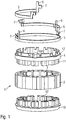
- Fig. 1 shows an exploded perspective view of a stator arrangement 1.
- the stator arrangement 1 is designed for an electrical machine, for example an electrical three-phase motor or an electrical three-phase generator.
- the stator arrangement 1 has a stator laminated core 2 which has a multiplicity of stator teeth 3.
- the stator laminated core 2 is formed from a large number of stamped laminations which are electrically and mechanically connected to one another. Other configurations of a stator, for example a one-piece design, are of course also possible.
- stator teeth 3 of the stator laminated core 2 serve to accommodate a stator winding.
- the stator windings are wound around the stator teeth 3.
- a contacting device 4 is shown above the stator laminated core 2.
- the contacting device 4 is formed, for example, from a plastic.
- the contacting device 4 has toothed insulation sections 12 which can be connected in a positive and non-positive manner to corresponding recesses in the stator laminated core 2.
- the contacting device 4 has a plurality of recesses 13, which are designed to receive the contact conductors 5.
- the contact conductors 5 are shown above the contacting device 4. In this embodiment, three contact conductors 5 are received by the receptacle 13 of the contacting device 4.
- the contact conductors 5 are formed, for example, from a metal alloy.
- the contact conductors 5 are formed from a bronze alloy.
- the contact conductors 5 have a semicircular shape.
- the contact conductors 5 each have connection lugs 6, which are designed to make contact with an external connection unit (not shown here).
- the connection lugs 6 extend in the axial direction of the stator arrangement 1.
- the contact conductors 5 have hooks 7, in which the winding wire ends 14 of the stator windings 9 can be inserted and / or clamped.
- the hooks 7 are preferably formed on the terminal lugs 6 of the contact conductors 5 and protrude from them.
- each contact conductor 5 has two hooks 7 on.
- the hooks 7 are arranged laterally on the contact conductors 5 and extend in the radial direction.
- an insulating washer 10 is shown below the stator laminated core 2, which forms the lower end of the stator arrangement 1.
- the insulating end plate 10 has tooth insulation sections 11, which cover and electrically insulate a lower part of the stator teeth, and around which the stator winding is wound.
- three contact conductors 5 are shown. It is of course possible for more than three or fewer than three contact conductors 5 to be used, depending on the field of application and embodiment of the electrical machine or the stator arrangement 1.
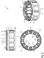
- Fig. 2 shows different views of the stator arrangement 1 with stator windings 9 Fig. 2 a side view of the stator arrangement 2 is shown. A top view of the stator arrangement 1 is shown at the bottom left. A perspective view of the stator arrangement 1 is shown at the bottom right.
- the stator teeth 3 of the stator core 2 are provided with stator windings 9.
- a one-piece wire is used for the stator windings 9 of the stator teeth 3.1 and 3.2.
- the winding end 14 of the stator winding 9 is clamped in the hook 7.1 of a contact conductor 5.
- the stator winding 9 of the stator teeth 3.3 and 3.4 is also formed from a one-piece wire. The end of these stator windings 9 is clamped in the hook 7.2 of the contact conductor 5.
- the stator windings 9 of the stator teeth 3.1, 3.2, 3.3 and 3.4 electrically coupled together.
- stator windings 9 This results in a very simple connection of the stator windings 9 without stator windings 9 which have been crossed over several times. In this way, the stator windings 9 can be wound very easily around the stator teeth 3. A complicated laying of the winding wire ends 14 is not necessary. This configuration is particularly suitable for needle windings.
- the contact conductors 5 can have more than two hooks 7.1, 7.2.
- a contact conductor 5 could be designed such that it electrically couples the stator windings 9 of the stator teeth 3.1, 3.3 and 3.5 to one another.
- the number of connecting lugs 6 can also be adapted to the respective field of application or the particular design of the electrical machine.
- Fig. 3 shows different views of the stator arrangement 1 without the stator winding 9
- Fig. 3 is a Side view of the stator assembly 1 shown.
- a top view of the stator arrangement 1 is shown at the bottom left.
- a perspective view of the stator arrangement 1 is shown at the bottom right.
- semicircular sections 11 are provided on the contacting device 4.
- the semicircular tooth insulating sections 11 form the upper section of a stator tooth 3 and electrically isolate it.
- - semicircular tooth insulation sections 12 are formed, which form the lower section of a stator tooth 3 and electrically insulate it. Due to the semicircular design of the tooth insulation sections 11 and 12, the winding can be done very easily.
- a series of grooves 15 can be provided on both sides, by means of which the stator winding 9 can be fixed during winding onto the stator teeth 3. This prevents the stator winding 9 from slipping from the stator tooth 3 during the winding of the stator winding 9.
- Fig. 4 represents a contact conductor 5.
- the contact conductor 5 is punched out of sheet metal, for example, and then in a further process step into the desired shape, which is shown in FIG Fig. 4 is shown, reshaped.
- the contact conductor 5 has a first middle section 5.1 and a second middle section 5.2, which adjoin one another at a bend 17.
- the two central sections 5.1, 5.2 are radially offset from one another by the bend 17.
- the kink 17 serves to create space for a further contact conductor 5.
- the contact conductors 5 in one plane in the recesses 13 of the Contacting device 4 added.
- the kink 17 makes it possible for the contact conductors 5 to be arranged in one plane.
- a connecting lug 6 is formed at one end 18 of the contact conductor 5.
- the connection lug 6 serves for the electrical contacting of an external connection unit, which supplies the stator with electrical energy or extracts electrical energy from the stator by the electric motor operated as a generator.
- a hook 7 is provided on the side of the connecting lug 6.
- the hook 7 is formed by folding the contact conductor material twice. The first fold serves to increase the thickness of the contact conductor material and the second fold serves to shape the hook 7. In this way, the thickness of the hook 7 is increased so that it is suitable for being connected to the winding end 14 of the stator winding 9 by welding ,
- a second hook 7 is provided at the opposite end 19 of the contact conductor 5. This hook 7 also serves to receive a corresponding winding wire end 14.
- the contact conductor 5 in Fig. 4 two hooks 7 and a bend 17 are provided.
- the contact conductor 5 it is possible for the contact conductor 5 to have only one hook 7 and no kink 17. Furthermore, it is also possible for the contact conductor 5 to have more than two hooks and more than one kink 17. Depending on the field of application and design of the electrical machine, the number of hooks 7 and the number of kinks 17 can be adapted.
Landscapes
- Engineering & Computer Science (AREA)
- Power Engineering (AREA)
- Insulation, Fastening Of Motor, Generator Windings (AREA)
- Manufacture Of Motors, Generators (AREA)
- Windings For Motors And Generators (AREA)
Claims (8)
- Système de stator (1) pour une machine électrique, comportant un empilage de tôles de stator (2),
comportant une pluralité d'enroulements de stator (9), comportant un dispositif de mise en contact (4), lequel comporte au moins un conducteur de contact (5) en tôle, lequel est réalisé pour relier électriquement l'un à l'autre au moins deux enroulements de stator (9), dans lequel un conducteur de contact (5) respectif comporte au moins une languette de raccordement (6) pour coupler électriquement une unité de raccordement au dispositif de mise en contact (4) ainsi qu'au moins un crochet (7) pour recevoir une extrémité de fil d'enroulement (14) d'un enroulement de stator (9) respectif relié électriquement au conducteur de contact (5), caractérisé en ce que le crochet (7) est réalisé par un premier pli de la tôle du conducteur de contact (5) afin de doubler l'épaisseur de la tôle du conducteur de contact (5), et par un deuxième pli de la tôle afin de réaliser le contour du crochet (7). - Système de stator selon la revendication 1, caractérisé en ce qu'une extrémité respective de fil d'enroulement (14) est bloquée par engagement de force et/ou par complémentarité de formes dans un crochet (7) ordonné à l'extrémité de fil d'enroulement (14).
- Système de stator selon l'une des revendications précédentes, caractérisé en ce que l'extrémité de fil d'enroulement (14) est sertie à chaud avec le crochet (7).
- Système de stator selon l'une des revendications précédentes, caractérisé en ce qu'un conducteur de contact respectif (5) comporte au moins deux crochets (7).
- Système de stator selon l'une des revendications précédentes, caractérisé en ce que le crochet (7) est réalisé sur la languette de raccordement (6).
- Système de stator selon l'une des revendications précédentes, caractérisé en ce que le dispositif de mise en contact (4) comporte une pièce de support pour recevoir le conducteur de contact, laquelle est réalisée en plastique.
- Système de stator selon l'une des revendications précédentes, caractérisé en ce que l'empilage de tôles de stator (2) forme une pluralité de dents de stator (3), sur lesquelles est prévue une pluralité d'enroulements de stator (9), dans lequel le dispositif de mise en contact (4) et un disque isolant (10) sont prévus, lesquels recouvrent et isolent les dents de stator au moyen de sections d'isolation de dents (11, 12) réalisée sur le dispositif de mise en contact (4) et sur le disque isolant (10), dans lequel la section d'isolation de dents (11) comporte des sillons (15) dans la direction d'enroulement du fil d'enroulement respectif, lesquels empêchent l'enroulement de stator (9) de glisser de la dent de stator respective (3).
- Machine électrique comportant :- un système de stator (1) selon l'une des revendications précédentes et- un rotor disposé en rotation et agencé à l'intérieur d'un évidement cylindrique du système de stator (1).
Applications Claiming Priority (2)
| Application Number | Priority Date | Filing Date | Title |
|---|---|---|---|
| DE102012202131A DE102012202131A1 (de) | 2012-02-13 | 2012-02-13 | Statoranordnung und elektrische Maschine |
| PCT/EP2013/000414 WO2013120603A2 (fr) | 2012-02-13 | 2013-02-13 | Dispositif stator et moteur électrique |
Publications (2)
| Publication Number | Publication Date |
|---|---|
| EP2815486A2 EP2815486A2 (fr) | 2014-12-24 |
| EP2815486B1 true EP2815486B1 (fr) | 2020-01-08 |
Family
ID=48771382
Family Applications (1)
| Application Number | Title | Priority Date | Filing Date |
|---|---|---|---|
| EP13734958.5A Active EP2815486B1 (fr) | 2012-02-13 | 2013-02-13 | Dispositif stator et moteur électrique |
Country Status (6)
| Country | Link |
|---|---|
| US (1) | US9608488B2 (fr) |
| EP (1) | EP2815486B1 (fr) |
| KR (1) | KR101722306B1 (fr) |
| CN (1) | CN104272563B (fr) |
| DE (1) | DE102012202131A1 (fr) |
| WO (1) | WO2013120603A2 (fr) |
Families Citing this family (11)
| Publication number | Priority date | Publication date | Assignee | Title |
|---|---|---|---|---|
| FR3015795B1 (fr) * | 2013-12-20 | 2017-08-25 | Valeo Equip Electr Moteur | Interconnecteur pour stator de machine electrique et stator de machine electrique comportant un tel interconnecteur |
| FR3018964B1 (fr) * | 2014-03-24 | 2016-03-04 | Valeo Equip Electr Moteur | Element d'interconnexion pour le branchement des bobines du stator |
| DE102014008327A1 (de) * | 2014-06-12 | 2015-12-17 | SIEVA d.o.o. - poslovna enota Idrija | Stator einer elektrischen Maschine |
| DE102015200093A1 (de) * | 2015-01-07 | 2016-07-07 | Robert Bosch Gmbh | Verschaltungsplatte eines Stators für eine elektrische Maschine und Verfahren zum Herstellen einer solchen |
| DE102015209041A1 (de) * | 2015-05-18 | 2016-11-24 | Robert Bosch Gmbh | Stator für eine elektrische Maschine, sowie Verfahren zur Herstellung eines solchen |
| GB2544523B (en) * | 2015-11-20 | 2022-02-09 | Valeo Air Man Uk Limited | A stator and busbar assembly for an electric supercharger |
| DE102016213710A1 (de) * | 2016-07-26 | 2018-02-01 | Robert Bosch Gmbh | Stator für eine elektrische Maschine, sowie Verfahren zur Herstellung eines solchen |
| CN109787392A (zh) * | 2017-11-14 | 2019-05-21 | 南京德朔实业有限公司 | 一种电动工具及电机,以及定子装置 |
| DE102019111825A1 (de) * | 2019-05-07 | 2020-11-12 | Schaeffler Technologies AG & Co. KG | Stator für eine elektrische Maschine |
| DE102021101504B4 (de) | 2021-01-25 | 2022-08-04 | Schaeffler Technologies AG & Co. KG | Verschaltungsring |
| DE102021118819A1 (de) | 2021-07-21 | 2023-01-26 | Bühler Motor GmbH | Stator einer elektrischen Antriebseinheit und Verfahren zu seiner Herstellung |
Citations (1)
| Publication number | Priority date | Publication date | Assignee | Title |
|---|---|---|---|---|
| DE10318816A1 (de) * | 2003-04-17 | 2004-11-25 | Minebea Co., Ltd. | Stator mit Verschaltungsstruktur für Statorwicklungen |
Family Cites Families (11)
| Publication number | Priority date | Publication date | Assignee | Title |
|---|---|---|---|---|
| JPH10304605A (ja) * | 1997-04-24 | 1998-11-13 | Toshiba Corp | 直流モータ |
| EP1526628B1 (fr) * | 2003-10-22 | 2011-03-02 | Brose Fahrzeugteile GmbH & Co. KG, Würzburg | Unité de connexion d'un stator de moteur électrique |
| JP4783012B2 (ja) * | 2004-12-28 | 2011-09-28 | 日立オートモティブシステムズ株式会社 | 電動パワーステアリング用モータ及びその製造方法 |
| JP4353950B2 (ja) * | 2006-03-06 | 2009-10-28 | 三菱電機株式会社 | 回転電機 |
| JP5028869B2 (ja) * | 2006-06-05 | 2012-09-19 | 日本電産株式会社 | ブラシレスモータ |
| DE202009000415U1 (de) * | 2008-02-12 | 2009-06-18 | Ebm-Papst St. Georgen Gmbh & Co. Kg | Elektronisch kommutierter Motor |
| DE102009001830A1 (de) * | 2009-03-25 | 2010-10-07 | Ferchau Engineering Gmbh | Stator für eine elektrische Maschine mit einer Verschaltungseinrichtung |
| IT1397784B1 (it) * | 2010-01-15 | 2013-01-24 | Gate Srl | Collettore per lo statore di un motore brushless in corrente continua a magneti permanenti |
| JP5740931B2 (ja) * | 2010-03-03 | 2015-07-01 | 日本電産株式会社 | 分割ステータ、及びモータ |
| JP5652004B2 (ja) * | 2010-06-02 | 2015-01-14 | 日産自動車株式会社 | 配電構造部品およびその製造方法 |
| DE102010033699B4 (de) * | 2010-07-30 | 2020-10-29 | Stöber Antriebstechnik GmbH & Co. KG | Schaltkopf für Elektromotoren und Verfahren zum Verbinden eines Schaltkopfes mit den Anschlusslitzen einer Elektromotorwicklung |
-
2012
- 2012-02-13 DE DE102012202131A patent/DE102012202131A1/de not_active Withdrawn
-
2013
- 2013-02-13 US US14/375,482 patent/US9608488B2/en active Active
- 2013-02-13 KR KR1020147025118A patent/KR101722306B1/ko active IP Right Grant
- 2013-02-13 WO PCT/EP2013/000414 patent/WO2013120603A2/fr active Application Filing
- 2013-02-13 CN CN201380009149.XA patent/CN104272563B/zh not_active Expired - Fee Related
- 2013-02-13 EP EP13734958.5A patent/EP2815486B1/fr active Active
Patent Citations (1)
| Publication number | Priority date | Publication date | Assignee | Title |
|---|---|---|---|---|
| DE10318816A1 (de) * | 2003-04-17 | 2004-11-25 | Minebea Co., Ltd. | Stator mit Verschaltungsstruktur für Statorwicklungen |
Also Published As
| Publication number | Publication date |
|---|---|
| EP2815486A2 (fr) | 2014-12-24 |
| KR20140133850A (ko) | 2014-11-20 |
| CN104272563B (zh) | 2017-05-17 |
| KR101722306B1 (ko) | 2017-03-31 |
| US20150015100A1 (en) | 2015-01-15 |
| US9608488B2 (en) | 2017-03-28 |
| WO2013120603A3 (fr) | 2014-09-04 |
| CN104272563A (zh) | 2015-01-07 |
| WO2013120603A2 (fr) | 2013-08-22 |
| DE102012202131A1 (de) | 2013-08-14 |
Similar Documents
| Publication | Publication Date | Title |
|---|---|---|
| EP2815486B1 (fr) | Dispositif stator et moteur électrique | |
| EP3320600B1 (fr) | Arrangement de stator, machine électrique à courant triphasé et procédé de fabrication d'un arrangement de stator | |
| EP1642376B1 (fr) | Element de connexion pour bobinage d'une machine electrique | |
| WO2016110427A1 (fr) | Stator pour machine électrique et procédé de fabrication d'un tel stator | |
| WO2016110425A1 (fr) | Pièce d'interconnexion d'un stator pour machine électrique et procédé de fabrication d'une telle pièce | |
| EP3895282B1 (fr) | Stator, composant de raccordement et machine électrique | |
| DE202015008207U1 (de) | Stator eines Elektromotors sowie Schalteinheit hierfür | |
| WO2006029992A1 (fr) | Moteur synchrone a excitation permanente, a enroulements a fils plats | |
| EP2606559B1 (fr) | Dispositif de mise en contact électrique dans un stator de moteur électrique | |
| DE112008002752T5 (de) | Stator und rotierende elektrische Maschine | |
| DE102018214111A1 (de) | Stator für eine elektrische Maschine, eine elektrische Maschine und Verfahren zum Herstellen einer solchen elektrischen Maschine | |
| DE202014010565U1 (de) | Stator eines Elektromotors mit einer Verschaltungseinheit | |
| EP3216113B1 (fr) | Rotor or stator avec tête de bobinage emboîté courte | |
| WO2016110423A1 (fr) | Plaque de câblage pour un stator d'une machine électrique et procédé de fabrication de ladite plaque de câblage | |
| WO2009013312A2 (fr) | Machine électrique | |
| DE102019202911A1 (de) | Verschaltungsanordnung und Stator für eine elektrische Maschine | |
| DE112015006399T5 (de) | Elektrische rotationsmaschine | |
| DE102019210308A1 (de) | Elektrische Maschine mit gekühlten Stromschienen | |
| DE102018126777A1 (de) | Pumpe aufweisend einen Elektromotor mit kompakter Sammelschieneneinheit | |
| EP2342799B1 (fr) | Machine électrique présentant un élément de contact pour la connexion électrique de composants électriques | |
| DE102018126776A1 (de) | Elektromotor mit kompakter Sammelschieneneinheit | |
| DE102015226416A1 (de) | Elektrische Maschine | |
| WO2022243018A1 (fr) | Ensemble bobine | |
| DE102019210126A1 (de) | Stator für eine elektrische Maschine | |
| DE102022212650A1 (de) | Fahrzeug, elektrische Maschine, Windungsanordnung und Verfahren zum Her-stellen einer Windungsanordnung für eine elektrische Maschine |
Legal Events
| Date | Code | Title | Description |
|---|---|---|---|
| PUAI | Public reference made under article 153(3) epc to a published international application that has entered the european phase |
Free format text: ORIGINAL CODE: 0009012 |
|
| 17P | Request for examination filed |
Effective date: 20140729 |
|
| AK | Designated contracting states |
Kind code of ref document: A2 Designated state(s): AL AT BE BG CH CY CZ DE DK EE ES FI FR GB GR HR HU IE IS IT LI LT LU LV MC MK MT NL NO PL PT RO RS SE SI SK SM TR |
|
| AX | Request for extension of the european patent |
Extension state: BA ME |
|
| RIN1 | Information on inventor provided before grant (corrected) |
Inventor name: BELZNER, VERONIQUE Inventor name: MARTIN, CHRISTIAN Inventor name: KOCH, KEVIN |
|
| R17P | Request for examination filed (corrected) |
Effective date: 20150304 |
|
| RBV | Designated contracting states (corrected) |
Designated state(s): AL AT BE BG CH CY CZ DE DK EE ES FI FR GB GR HR HU IE IS IT LI LT LU LV MC MK MT NL NO PL PT RO RS SE SI SK SM TR |
|
| DAX | Request for extension of the european patent (deleted) | ||
| GRAP | Despatch of communication of intention to grant a patent |
Free format text: ORIGINAL CODE: EPIDOSNIGR1 |
|
| STAA | Information on the status of an ep patent application or granted ep patent |
Free format text: STATUS: GRANT OF PATENT IS INTENDED |
|
| INTG | Intention to grant announced |
Effective date: 20190809 |
|
| GRAS | Grant fee paid |
Free format text: ORIGINAL CODE: EPIDOSNIGR3 |
|
| GRAA | (expected) grant |
Free format text: ORIGINAL CODE: 0009210 |
|
| STAA | Information on the status of an ep patent application or granted ep patent |
Free format text: STATUS: THE PATENT HAS BEEN GRANTED |
|
| AK | Designated contracting states |
Kind code of ref document: B1 Designated state(s): AL AT BE BG CH CY CZ DE DK EE ES FI FR GB GR HR HU IE IS IT LI LT LU LV MC MK MT NL NO PL PT RO RS SE SI SK SM TR |
|
| REG | Reference to a national code |
Ref country code: GB Ref legal event code: FG4D Free format text: NOT ENGLISH |
|
| REG | Reference to a national code |
Ref country code: CH Ref legal event code: EP |
|
| REG | Reference to a national code |
Ref country code: IE Ref legal event code: FG4D Free format text: LANGUAGE OF EP DOCUMENT: GERMAN |
|
| REG | Reference to a national code |
Ref country code: DE Ref legal event code: R096 Ref document number: 502013014174 Country of ref document: DE |
|
| REG | Reference to a national code |
Ref country code: AT Ref legal event code: REF Ref document number: 1223885 Country of ref document: AT Kind code of ref document: T Effective date: 20200215 |
|
| REG | Reference to a national code |
Ref country code: DE Ref legal event code: R081 Ref document number: 502013014174 Country of ref document: DE Owner name: BROSE FAHRZEUGTEILE SE & CO. KOMMANDITGESELLSC, DE Free format text: FORMER OWNER: BROSE FAHRZEUGTEILE GMBH & CO. KOMMANDITGESELLSCHAFT, WUERZBURG, 97076 WUERZBURG, DE |
|
| REG | Reference to a national code |
Ref country code: NL Ref legal event code: MP Effective date: 20200108 |
|
| REG | Reference to a national code |
Ref country code: LT Ref legal event code: MG4D |
|
| PG25 | Lapsed in a contracting state [announced via postgrant information from national office to epo] |
Ref country code: LT Free format text: LAPSE BECAUSE OF FAILURE TO SUBMIT A TRANSLATION OF THE DESCRIPTION OR TO PAY THE FEE WITHIN THE PRESCRIBED TIME-LIMIT Effective date: 20200108 Ref country code: FI Free format text: LAPSE BECAUSE OF FAILURE TO SUBMIT A TRANSLATION OF THE DESCRIPTION OR TO PAY THE FEE WITHIN THE PRESCRIBED TIME-LIMIT Effective date: 20200108 Ref country code: NO Free format text: LAPSE BECAUSE OF FAILURE TO SUBMIT A TRANSLATION OF THE DESCRIPTION OR TO PAY THE FEE WITHIN THE PRESCRIBED TIME-LIMIT Effective date: 20200408 Ref country code: PT Free format text: LAPSE BECAUSE OF FAILURE TO SUBMIT A TRANSLATION OF THE DESCRIPTION OR TO PAY THE FEE WITHIN THE PRESCRIBED TIME-LIMIT Effective date: 20200531 Ref country code: NL Free format text: LAPSE BECAUSE OF FAILURE TO SUBMIT A TRANSLATION OF THE DESCRIPTION OR TO PAY THE FEE WITHIN THE PRESCRIBED TIME-LIMIT Effective date: 20200108 Ref country code: RS Free format text: LAPSE BECAUSE OF FAILURE TO SUBMIT A TRANSLATION OF THE DESCRIPTION OR TO PAY THE FEE WITHIN THE PRESCRIBED TIME-LIMIT Effective date: 20200108 |
|
| PG25 | Lapsed in a contracting state [announced via postgrant information from national office to epo] |
Ref country code: GR Free format text: LAPSE BECAUSE OF FAILURE TO SUBMIT A TRANSLATION OF THE DESCRIPTION OR TO PAY THE FEE WITHIN THE PRESCRIBED TIME-LIMIT Effective date: 20200409 Ref country code: IS Free format text: LAPSE BECAUSE OF FAILURE TO SUBMIT A TRANSLATION OF THE DESCRIPTION OR TO PAY THE FEE WITHIN THE PRESCRIBED TIME-LIMIT Effective date: 20200508 Ref country code: BG Free format text: LAPSE BECAUSE OF FAILURE TO SUBMIT A TRANSLATION OF THE DESCRIPTION OR TO PAY THE FEE WITHIN THE PRESCRIBED TIME-LIMIT Effective date: 20200408 Ref country code: HR Free format text: LAPSE BECAUSE OF FAILURE TO SUBMIT A TRANSLATION OF THE DESCRIPTION OR TO PAY THE FEE WITHIN THE PRESCRIBED TIME-LIMIT Effective date: 20200108 Ref country code: SE Free format text: LAPSE BECAUSE OF FAILURE TO SUBMIT A TRANSLATION OF THE DESCRIPTION OR TO PAY THE FEE WITHIN THE PRESCRIBED TIME-LIMIT Effective date: 20200108 Ref country code: LV Free format text: LAPSE BECAUSE OF FAILURE TO SUBMIT A TRANSLATION OF THE DESCRIPTION OR TO PAY THE FEE WITHIN THE PRESCRIBED TIME-LIMIT Effective date: 20200108 |
|
| REG | Reference to a national code |
Ref country code: CH Ref legal event code: PL |
|
| REG | Reference to a national code |
Ref country code: DE Ref legal event code: R097 Ref document number: 502013014174 Country of ref document: DE |
|
| REG | Reference to a national code |
Ref country code: BE Ref legal event code: MM Effective date: 20200229 |
|
| PG25 | Lapsed in a contracting state [announced via postgrant information from national office to epo] |
Ref country code: SM Free format text: LAPSE BECAUSE OF FAILURE TO SUBMIT A TRANSLATION OF THE DESCRIPTION OR TO PAY THE FEE WITHIN THE PRESCRIBED TIME-LIMIT Effective date: 20200108 Ref country code: EE Free format text: LAPSE BECAUSE OF FAILURE TO SUBMIT A TRANSLATION OF THE DESCRIPTION OR TO PAY THE FEE WITHIN THE PRESCRIBED TIME-LIMIT Effective date: 20200108 Ref country code: ES Free format text: LAPSE BECAUSE OF FAILURE TO SUBMIT A TRANSLATION OF THE DESCRIPTION OR TO PAY THE FEE WITHIN THE PRESCRIBED TIME-LIMIT Effective date: 20200108 Ref country code: DK Free format text: LAPSE BECAUSE OF FAILURE TO SUBMIT A TRANSLATION OF THE DESCRIPTION OR TO PAY THE FEE WITHIN THE PRESCRIBED TIME-LIMIT Effective date: 20200108 Ref country code: LU Free format text: LAPSE BECAUSE OF NON-PAYMENT OF DUE FEES Effective date: 20200213 Ref country code: MC Free format text: LAPSE BECAUSE OF FAILURE TO SUBMIT A TRANSLATION OF THE DESCRIPTION OR TO PAY THE FEE WITHIN THE PRESCRIBED TIME-LIMIT Effective date: 20200108 Ref country code: CZ Free format text: LAPSE BECAUSE OF FAILURE TO SUBMIT A TRANSLATION OF THE DESCRIPTION OR TO PAY THE FEE WITHIN THE PRESCRIBED TIME-LIMIT Effective date: 20200108 Ref country code: RO Free format text: LAPSE BECAUSE OF FAILURE TO SUBMIT A TRANSLATION OF THE DESCRIPTION OR TO PAY THE FEE WITHIN THE PRESCRIBED TIME-LIMIT Effective date: 20200108 Ref country code: SK Free format text: LAPSE BECAUSE OF FAILURE TO SUBMIT A TRANSLATION OF THE DESCRIPTION OR TO PAY THE FEE WITHIN THE PRESCRIBED TIME-LIMIT Effective date: 20200108 |
|
| PLBE | No opposition filed within time limit |
Free format text: ORIGINAL CODE: 0009261 |
|
| STAA | Information on the status of an ep patent application or granted ep patent |
Free format text: STATUS: NO OPPOSITION FILED WITHIN TIME LIMIT |
|
| PG25 | Lapsed in a contracting state [announced via postgrant information from national office to epo] |
Ref country code: CH Free format text: LAPSE BECAUSE OF NON-PAYMENT OF DUE FEES Effective date: 20200229 Ref country code: LI Free format text: LAPSE BECAUSE OF NON-PAYMENT OF DUE FEES Effective date: 20200229 |
|
| 26N | No opposition filed |
Effective date: 20201009 |
|
| PG25 | Lapsed in a contracting state [announced via postgrant information from national office to epo] |
Ref country code: FR Free format text: LAPSE BECAUSE OF NON-PAYMENT OF DUE FEES Effective date: 20200308 Ref country code: IT Free format text: LAPSE BECAUSE OF FAILURE TO SUBMIT A TRANSLATION OF THE DESCRIPTION OR TO PAY THE FEE WITHIN THE PRESCRIBED TIME-LIMIT Effective date: 20200108 Ref country code: IE Free format text: LAPSE BECAUSE OF NON-PAYMENT OF DUE FEES Effective date: 20200213 |
|
| PG25 | Lapsed in a contracting state [announced via postgrant information from national office to epo] |
Ref country code: BE Free format text: LAPSE BECAUSE OF NON-PAYMENT OF DUE FEES Effective date: 20200229 Ref country code: PL Free format text: LAPSE BECAUSE OF FAILURE TO SUBMIT A TRANSLATION OF THE DESCRIPTION OR TO PAY THE FEE WITHIN THE PRESCRIBED TIME-LIMIT Effective date: 20200108 Ref country code: SI Free format text: LAPSE BECAUSE OF FAILURE TO SUBMIT A TRANSLATION OF THE DESCRIPTION OR TO PAY THE FEE WITHIN THE PRESCRIBED TIME-LIMIT Effective date: 20200108 |
|
| GBPC | Gb: european patent ceased through non-payment of renewal fee |
Effective date: 20200408 |
|
| REG | Reference to a national code |
Ref country code: AT Ref legal event code: MM01 Ref document number: 1223885 Country of ref document: AT Kind code of ref document: T Effective date: 20200213 |
|
| PG25 | Lapsed in a contracting state [announced via postgrant information from national office to epo] |
Ref country code: GB Free format text: LAPSE BECAUSE OF NON-PAYMENT OF DUE FEES Effective date: 20200408 |
|
| PG25 | Lapsed in a contracting state [announced via postgrant information from national office to epo] |
Ref country code: AT Free format text: LAPSE BECAUSE OF NON-PAYMENT OF DUE FEES Effective date: 20200213 |
|
| PG25 | Lapsed in a contracting state [announced via postgrant information from national office to epo] |
Ref country code: TR Free format text: LAPSE BECAUSE OF FAILURE TO SUBMIT A TRANSLATION OF THE DESCRIPTION OR TO PAY THE FEE WITHIN THE PRESCRIBED TIME-LIMIT Effective date: 20200108 Ref country code: MT Free format text: LAPSE BECAUSE OF FAILURE TO SUBMIT A TRANSLATION OF THE DESCRIPTION OR TO PAY THE FEE WITHIN THE PRESCRIBED TIME-LIMIT Effective date: 20200108 Ref country code: CY Free format text: LAPSE BECAUSE OF FAILURE TO SUBMIT A TRANSLATION OF THE DESCRIPTION OR TO PAY THE FEE WITHIN THE PRESCRIBED TIME-LIMIT Effective date: 20200108 |
|
| PG25 | Lapsed in a contracting state [announced via postgrant information from national office to epo] |
Ref country code: MK Free format text: LAPSE BECAUSE OF FAILURE TO SUBMIT A TRANSLATION OF THE DESCRIPTION OR TO PAY THE FEE WITHIN THE PRESCRIBED TIME-LIMIT Effective date: 20200108 Ref country code: AL Free format text: LAPSE BECAUSE OF FAILURE TO SUBMIT A TRANSLATION OF THE DESCRIPTION OR TO PAY THE FEE WITHIN THE PRESCRIBED TIME-LIMIT Effective date: 20200108 |
|
| PGFP | Annual fee paid to national office [announced via postgrant information from national office to epo] |
Ref country code: DE Payment date: 20240229 Year of fee payment: 12 |