EP2813751A1 - Neuartiges rückbeleuchtungsmodul für flüssigkristallanzeige - Google Patents
Neuartiges rückbeleuchtungsmodul für flüssigkristallanzeige Download PDFInfo
- Publication number
- EP2813751A1 EP2813751A1 EP12868306.7A EP12868306A EP2813751A1 EP 2813751 A1 EP2813751 A1 EP 2813751A1 EP 12868306 A EP12868306 A EP 12868306A EP 2813751 A1 EP2813751 A1 EP 2813751A1
- Authority
- EP
- European Patent Office
- Prior art keywords
- emergent surface
- emergent
- prism
- light
- parallelogram
- Prior art date
- Legal status (The legal status is an assumption and is not a legal conclusion. Google has not performed a legal analysis and makes no representation as to the accuracy of the status listed.)
- Withdrawn
Links
- 239000004973 liquid crystal related substance Substances 0.000 title claims abstract description 39
- 230000003287 optical effect Effects 0.000 claims description 17
- 239000000463 material Substances 0.000 claims description 14
- 230000001154 acute effect Effects 0.000 claims description 12
- 239000002184 metal Substances 0.000 claims description 2
- 238000004519 manufacturing process Methods 0.000 abstract description 10
- 238000010586 diagram Methods 0.000 description 9
- 230000005540 biological transmission Effects 0.000 description 3
- 230000007423 decrease Effects 0.000 description 3
- 238000011161 development Methods 0.000 description 3
- 238000009792 diffusion process Methods 0.000 description 2
- 230000000694 effects Effects 0.000 description 2
- 238000012986 modification Methods 0.000 description 2
- 230000004048 modification Effects 0.000 description 2
- 239000000306 component Substances 0.000 description 1
- 239000008358 core component Substances 0.000 description 1
- 230000003247 decreasing effect Effects 0.000 description 1
- 230000007547 defect Effects 0.000 description 1
- 238000005265 energy consumption Methods 0.000 description 1
- 238000002474 experimental method Methods 0.000 description 1
- 238000004020 luminiscence type Methods 0.000 description 1
- 238000012545 processing Methods 0.000 description 1
- 230000009467 reduction Effects 0.000 description 1
- 238000004088 simulation Methods 0.000 description 1
Images


Classifications
-
- G—PHYSICS
- G02—OPTICS
- G02F—OPTICAL DEVICES OR ARRANGEMENTS FOR THE CONTROL OF LIGHT BY MODIFICATION OF THE OPTICAL PROPERTIES OF THE MEDIA OF THE ELEMENTS INVOLVED THEREIN; NON-LINEAR OPTICS; FREQUENCY-CHANGING OF LIGHT; OPTICAL LOGIC ELEMENTS; OPTICAL ANALOGUE/DIGITAL CONVERTERS
- G02F1/00—Devices or arrangements for the control of the intensity, colour, phase, polarisation or direction of light arriving from an independent light source, e.g. switching, gating or modulating; Non-linear optics
- G02F1/01—Devices or arrangements for the control of the intensity, colour, phase, polarisation or direction of light arriving from an independent light source, e.g. switching, gating or modulating; Non-linear optics for the control of the intensity, phase, polarisation or colour
- G02F1/13—Devices or arrangements for the control of the intensity, colour, phase, polarisation or direction of light arriving from an independent light source, e.g. switching, gating or modulating; Non-linear optics for the control of the intensity, phase, polarisation or colour based on liquid crystals, e.g. single liquid crystal display cells
- G02F1/133—Constructional arrangements; Operation of liquid crystal cells; Circuit arrangements
- G02F1/1333—Constructional arrangements; Manufacturing methods
- G02F1/1335—Structural association of cells with optical devices, e.g. polarisers or reflectors
- G02F1/1336—Illuminating devices
- G02F1/133615—Edge-illuminating devices, i.e. illuminating from the side
-
- G—PHYSICS
- G02—OPTICS
- G02B—OPTICAL ELEMENTS, SYSTEMS OR APPARATUS
- G02B6/00—Light guides; Structural details of arrangements comprising light guides and other optical elements, e.g. couplings
- G02B6/0001—Light guides; Structural details of arrangements comprising light guides and other optical elements, e.g. couplings specially adapted for lighting devices or systems
- G02B6/0011—Light guides; Structural details of arrangements comprising light guides and other optical elements, e.g. couplings specially adapted for lighting devices or systems the light guides being planar or of plate-like form
- G02B6/0033—Means for improving the coupling-out of light from the light guide
- G02B6/0035—Means for improving the coupling-out of light from the light guide provided on the surface of the light guide or in the bulk of it
- G02B6/0045—Means for improving the coupling-out of light from the light guide provided on the surface of the light guide or in the bulk of it by shaping at least a portion of the light guide
- G02B6/0046—Tapered light guide, e.g. wedge-shaped light guide
-
- G—PHYSICS
- G02—OPTICS
- G02B—OPTICAL ELEMENTS, SYSTEMS OR APPARATUS
- G02B6/00—Light guides; Structural details of arrangements comprising light guides and other optical elements, e.g. couplings
- G02B6/0001—Light guides; Structural details of arrangements comprising light guides and other optical elements, e.g. couplings specially adapted for lighting devices or systems
- G02B6/0011—Light guides; Structural details of arrangements comprising light guides and other optical elements, e.g. couplings specially adapted for lighting devices or systems the light guides being planar or of plate-like form
- G02B6/0033—Means for improving the coupling-out of light from the light guide
- G02B6/005—Means for improving the coupling-out of light from the light guide provided by one optical element, or plurality thereof, placed on the light output side of the light guide
- G02B6/0053—Prismatic sheet or layer; Brightness enhancement element, sheet or layer
-
- G—PHYSICS
- G02—OPTICS
- G02B—OPTICAL ELEMENTS, SYSTEMS OR APPARATUS
- G02B5/00—Optical elements other than lenses
- G02B5/04—Prisms
- G02B5/045—Prism arrays
-
- G—PHYSICS
- G02—OPTICS
- G02B—OPTICAL ELEMENTS, SYSTEMS OR APPARATUS
- G02B5/00—Optical elements other than lenses
- G02B5/08—Mirrors
- G02B5/0808—Mirrors having a single reflecting layer
-
- G—PHYSICS
- G02—OPTICS
- G02B—OPTICAL ELEMENTS, SYSTEMS OR APPARATUS
- G02B6/00—Light guides; Structural details of arrangements comprising light guides and other optical elements, e.g. couplings
- G02B6/0001—Light guides; Structural details of arrangements comprising light guides and other optical elements, e.g. couplings specially adapted for lighting devices or systems
- G02B6/0011—Light guides; Structural details of arrangements comprising light guides and other optical elements, e.g. couplings specially adapted for lighting devices or systems the light guides being planar or of plate-like form
- G02B6/0033—Means for improving the coupling-out of light from the light guide
- G02B6/005—Means for improving the coupling-out of light from the light guide provided by one optical element, or plurality thereof, placed on the light output side of the light guide
- G02B6/0055—Reflecting element, sheet or layer
-
- G—PHYSICS
- G02—OPTICS
- G02B—OPTICAL ELEMENTS, SYSTEMS OR APPARATUS
- G02B6/00—Light guides; Structural details of arrangements comprising light guides and other optical elements, e.g. couplings
- G02B6/0001—Light guides; Structural details of arrangements comprising light guides and other optical elements, e.g. couplings specially adapted for lighting devices or systems
- G02B6/0011—Light guides; Structural details of arrangements comprising light guides and other optical elements, e.g. couplings specially adapted for lighting devices or systems the light guides being planar or of plate-like form
- G02B6/0033—Means for improving the coupling-out of light from the light guide
- G02B6/0063—Means for improving the coupling-out of light from the light guide for extracting light out both the major surfaces of the light guide
-
- G—PHYSICS
- G02—OPTICS
- G02F—OPTICAL DEVICES OR ARRANGEMENTS FOR THE CONTROL OF LIGHT BY MODIFICATION OF THE OPTICAL PROPERTIES OF THE MEDIA OF THE ELEMENTS INVOLVED THEREIN; NON-LINEAR OPTICS; FREQUENCY-CHANGING OF LIGHT; OPTICAL LOGIC ELEMENTS; OPTICAL ANALOGUE/DIGITAL CONVERTERS
- G02F1/00—Devices or arrangements for the control of the intensity, colour, phase, polarisation or direction of light arriving from an independent light source, e.g. switching, gating or modulating; Non-linear optics
- G02F1/01—Devices or arrangements for the control of the intensity, colour, phase, polarisation or direction of light arriving from an independent light source, e.g. switching, gating or modulating; Non-linear optics for the control of the intensity, phase, polarisation or colour
- G02F1/13—Devices or arrangements for the control of the intensity, colour, phase, polarisation or direction of light arriving from an independent light source, e.g. switching, gating or modulating; Non-linear optics for the control of the intensity, phase, polarisation or colour based on liquid crystals, e.g. single liquid crystal display cells
- G02F1/133—Constructional arrangements; Operation of liquid crystal cells; Circuit arrangements
- G02F1/1333—Constructional arrangements; Manufacturing methods
- G02F1/1335—Structural association of cells with optical devices, e.g. polarisers or reflectors
- G02F1/1336—Illuminating devices
- G02F1/133602—Direct backlight
- G02F1/133606—Direct backlight including a specially adapted diffusing, scattering or light controlling members
- G02F1/133607—Direct backlight including a specially adapted diffusing, scattering or light controlling members the light controlling member including light directing or refracting elements, e.g. prisms or lenses
-
- G—PHYSICS
- G02—OPTICS
- G02F—OPTICAL DEVICES OR ARRANGEMENTS FOR THE CONTROL OF LIGHT BY MODIFICATION OF THE OPTICAL PROPERTIES OF THE MEDIA OF THE ELEMENTS INVOLVED THEREIN; NON-LINEAR OPTICS; FREQUENCY-CHANGING OF LIGHT; OPTICAL LOGIC ELEMENTS; OPTICAL ANALOGUE/DIGITAL CONVERTERS
- G02F1/00—Devices or arrangements for the control of the intensity, colour, phase, polarisation or direction of light arriving from an independent light source, e.g. switching, gating or modulating; Non-linear optics
- G02F1/01—Devices or arrangements for the control of the intensity, colour, phase, polarisation or direction of light arriving from an independent light source, e.g. switching, gating or modulating; Non-linear optics for the control of the intensity, phase, polarisation or colour
- G02F1/13—Devices or arrangements for the control of the intensity, colour, phase, polarisation or direction of light arriving from an independent light source, e.g. switching, gating or modulating; Non-linear optics for the control of the intensity, phase, polarisation or colour based on liquid crystals, e.g. single liquid crystal display cells
- G02F1/133—Constructional arrangements; Operation of liquid crystal cells; Circuit arrangements
- G02F1/1333—Constructional arrangements; Manufacturing methods
- G02F1/1335—Structural association of cells with optical devices, e.g. polarisers or reflectors
- G02F1/1336—Illuminating devices
- G02F1/133616—Front illuminating devices
Definitions
- the invention relates to a backlight module for a liquid crystal display, and more particularly to a novel backlight module for a liquid crystal display for generating parallel beams.
- LCD Liquid crystal display
- Liquid crystal in a panel of the LCD itself does not have luminescence property but utilizes a backlight module to provide a light source, thereby reaching the display effect of the LCD.
- the backlight source generally employs a light emitting diode (LED) or a cold cathode fluorescent source (CCFL) as the light source, light emitted by which travels through a light guide plate (LGP) and is coupled into the display.
- LED light emitting diode
- CCFL cold cathode fluorescent source
- LGP light guide plate
- a divergence angle of the light source is relatively large, and the energy that actually enters the LGP and is utilized is 10% below, thereby decreasing the efficiency of the whole display.
- the development of the large-sized TVs especially the development of the high definition television (HDTV), has higher requirements on the picture quality.
- a normal line that is perpendicular to the LCD is used as an axis, and light rays from a paraxial of the backlight source are highly utilized by the liquid crystal.
- the divergence angle of the backlight source is large, the light utilization decreases; besides, off-axis light rays of a large angle results in problems of contrast reduction, light leakage, and color washout.
- the light emitted by the backlight module generally satisfies certain collimation demands.
- the backlight module 1 includes: a light guide plate 10, a prism sheet 12, and a diffusion sheet 14.
- Light enters the light guide plate 10 via an incident plane 100. A part of the light directly emerges from the emergent plane 102, another part of the light emerges from a bottom plane 104, and the majority of the light is reflected one or several times inside the light guide plate 10 and is eventually ejected out of the light guide plate 10 via the emergent plane 102.
- the light ejected from the emergent plane 102 of the light guide plate 10 enters the prism sheet 12 via a prism plane 122, and a transmission direction of a majority of the light is changed by a plurality of prism structures 126 disposed on the prism plane 122 and the light is then ejected in a direction of a normal line of a top plane 124, and travels to the diffusion sheet 14.
- the backlight module 1 is capable of providing collimated light, the divergence angle of the collimated light is too large and it is difficult to effectively decrease the angle.
- the size of the reflection structure 128 is relatively large, the divergence angle of the reflected light is relatively large, and therefore, in order to decrease the divergence angle of the emergent light and to improve the collimation of the emergent light, the reflection structure 128 must be precisely manufactured, thereby increasing the difficulty and the production cost of the manufacturing process.
- WO 2008/100443 A2 published in 2008 has disclosed a compact collimating reflection sheet (CCR) capable of producing a parallel beam, as shown in FIG. 2 .
- the CCR is disposed at bottommost backlight module, and the whole structure has a ship-like shape.
- the light source is disposed at two ends of the collimation reflection sheet.
- the CCR includes an incident plane, which is also a reflective plane and has a zigzag structure. Each zigzag element has different angle and gradient. The light of different angle sent out by the light source is reflected by the zigzag structures having different angles and different gradients, and the transmission of the light is changed to eject the light perpendicularly to a liquid crystal screen.
- the structure depicted in FIG. 2 is capable of producing a collimated beam
- the light emitted from the light source is continuous and has a large angle and the reflection sheet of the collimated beam is in a continuous zigzag structure.
- the collimation effect of the produced collimated beam is not ideal.
- the discontinuous zigzag structure is finely designed, and each zigzag has specific angle and gradient, so that the processing difficulty is very large and the production cost is relatively high.
- a backlight module for a liquid crystal display comprises a light source, a triangular wedge for generating parallel beams, a reflecting device, and a deflection-collimating device, all of which being disposed in front of a liquid crystal display in sequence.
- the triangular wedge comprises a first incident surface, a first emergent surface, and a second emergent surface. An included angle formed between the first emergent surface and the second emergent surface is less than or equal to 5°.
- the first incident surface is opposite to the light source.
- the reflecting device is disposed at one side of the first emergent surface to reflect the light rays from the first emergent surface back to the triangular wedge.
- the deflection-collimating device is disposed between the second emergent surface and the liquid crystal display to refract parallel beams from the second emergent surface to generate light rays vertical to a plane of the liquid crystal display.
- the deflection-collimating device comprises a deflection prism assembly and the collimating prism.
- the deflection prism assembly comprises a plurality of parallelogram prisms arraying in the shape of a parallelogram in one dimensional direction; an acute angle of the parallelogram is more than or equal to 45°.
- the parallelogram prisms comprise a second incident surface and a third emergent surface. The second incident surface is parallel to the second emergent surface.
- the acute angle of the parallelogram at the side of the second incident surface is directed to the first incident surface, and an obtuse angle of the parallelogram is directed to a crosspoint of the first emergent surface and the second emergent surface.
- the collimating prism comprises a third incident surface and a fourth emergent surface.
- the third incident surface is parallel to the third emergent surface.
- the fourth emergent surface comprises a plurality of sawteeth in series which are asymmetric in one dimensional direction. An included angle formed between an inclined plane of the sawteeth and the third incident surface is less than or equal to 10°.
- the deflection prism assembly and the collimating prism are integrated to generate a deflection-collimating prism.
- the third incident surface is coincident with the third emergent surface.
- the deflection-collimating device comprises a deflection prism assembly and the collimating prism.
- the deflection prism assembly comprises a plurality of parallelogram prisms arraying in the shape of a parallelogram in one dimensional direction; an acute angle of the parallelogram is more than or equal to 45°.
- the parallelogram prisms comprise a second incident surface and a third emergent surface. The second incident surface is parallel to the second emergent surface.
- the acute angle of the parallelogram at the side of the second incident surface is directed to the first incident surface, and an obtuse angle of the parallelogram is directed to a crosspoint of the first emergent surface and the second emergent surface.
- the collimating prism comprises a third incident surface and a fifth emergent surface.
- the third incident surface is parallel to the third emergent surface.
- the fifth emergent surface is parallel to a plane of the liquid crystal display.
- An included angle formed between the third incident surface and the fifth emergent surface is less than or equal to 10°.
- the deflection prism assembly and the collimating prism are integrated to generate a prism wedge.
- the third incident surface is coincident with the third emergent surface.
- the reflecting device is a reflecting sheet made of optical material; the reflecting sheet comprises a metal or medium-plated reflecting surface. The reflecting surface is parallel to the first emergent surface.
- the triangular wedge is a wedge sheet made of optical materials.
- the parallelogram prisms are parallelogram prism sheets made of optical material
- the collimating prisms are collimating prism sheets made of optical material.
- the deflection-collimating prism is a deflection-collimating prism sheet made of optical material.
- the prism wedge is a prism wedge sheet made of optical material.
- the components of the backlight module have simple structures, uncomplicated manufacturing process, and low production costs.
- the resulting parallel beams have good collimation, thereby improving the light utilization rate and solving the defects of conventional LCDs such as light leakage, color cast, and low contrast degree.
- the disclosure of the invention provides a backlight module for a liquid crystal display (LCD) comprising an LED light source 2, a light reflector 3, a wedge sheet 4 for generating parallel beam, a reflecting sheet 5, a deflection prism sheet assembly 6, and a collimating prism sheet 7, all of which being disposed in front of a liquid crystal display 1 in sequence.
- the wedge sheet 4, the reflecting sheet 5, the deflection prism sheet assembly 6, and the collimating prism sheet 7 are all made of optical materials.
- the wedge sheet 4 comprises a first incident surface 41, a first emergent surface 42, and a second emergent surface 43. An included angle formed between the first emergent surface 42 and the second emergent surface 43 is 5°.
- the first incident surface 41 is opposite to the light source 2.
- the reflecting sheet 5 is disposed at one side of the first emergent surface 42.
- the reflecting sheet 5 comprises a metal-plated reflecting surface 51.
- the reflecting surface 51 is parallel to the first emergent surface 42 and reflects the light rays from the first emergent surface 42 back to the wedge sheet 4.
- the deflection prism sheet assembly 6 and the collimating prism sheet 7 are disposed in sequence between the second emergent surface 43 and the liquid crystal display 1 and form a deflection-collimating device which refract the parallel beam from the second emergent surface 43 to generate light rays vertical to the surface of the liquid crystal display 1.
- the deflection prism sheet assembly 6 comprises a plurality of parallelogram prism sheets 61 arraying in the shape of a parallelogram in one dimensional direction.
- the acute angle ⁇ of the parallelogram is 65°.
- the parallelogram prism sheets 61 comprise a second incident surface 62 and a third emergent surface 63.
- the second incident surface 62 is parallel to the second emergent surface 43.
- the acute angle ⁇ of the parallelogram at the side of the second incident surface 62 is directed to the first incident surface 41, while the obtuse angle ⁇ of the parallelogram is directed to a crosspoint of the first emergent surface 42 and the second emergent surface 43.
- the collimating prism sheet 7 comprises a third incident surface 71 and a fourth emergent surface 72.
- the third incident surface 71 is parallel to the third emergent surface 63.
- the fourth emergent surface 72 comprises a plurality of sawteeth 73 in series which are asymmetric in one dimensional direction.
- the included angle ⁇ formed between the inclined plane of the sawteeth 73 and the third incident surface 71 is 10°.
- FIG. 4 shows the working principle of the wedge sheet 4 which is the core component of the invention.
- Light rays emitted from the light source enter the wedge sheet 4 with different incident angles and are transmitted in the wedge sheet 4 on the basis of total reflection.
- the incident angle in the medium is less than or equal to the critical angle of the total reflection
- the light rays emerge from the second emergent surface 43 of the wedge sheet 4.
- the wedge sheet 4 is configured to converge the divergent lights from the light source 2 with large divergence angles by repeated total reflection to generate parallel beams which finally emerge out of the wedge sheet 4 with the incident angles being almost equal to the critical angle of the total reflection.
- FIGS. 5A and 5B show the divergence angles of the light rays before and after the treatment of the wedge sheet 4.
- FIG. 5A shows the distribution of the divergence angles of the light rays emitted from the LED light source 2, and the divergence angles are almost ⁇ 60°.
- the light rays are converged by the wedge sheet 4 to generate parallel beams having divergence angles of almost ⁇ 5°, as shown in FIG. 5B .
- FIG. 6 shows an optical path of a light ray transmitted in the wedge sheet 4 and the parallelogram prism sheets 61.
- the light ray 00 emitted from the light source 2 is refracted via the first incident surface 41 of the wedge sheet 4 to generate the refracted ray 01.
- the refracted ray 01 is totally reflected by the second emergent surface 43 of the wedge sheet 4 to generate the reflection ray 02.
- the reflection ray 02 is totally reflected by the first emergent surface 42 of the wedge sheet 4 to generate the reflection ray 03.
- FIG. 7 shows the reflection curve from an optically denser medium to an optically thinner medium based on the Snell's law of refraction. For example, assuming the refractive index of the medium is 1.5, the critical angle of the total reflection is about 42°.
- the light ray 03 When the light ray 03 rays on the second emergent surface 43, and the included angle ⁇ 3 formed by the light ray 03 and the normal line is less than or equal to the critical angle of the total reflection, the light ray 03 is refracted by the second emergent surface 43 to generate the light ray 04.
- the light ray 04 emitted from the second emergent surface 43 of the wedge sheet 4 is generated in the form of approximating to the critical angle of the total reflection, and thus has a large incident angle with the liquid crystal display 1, which cannot meet the utilization requirement.
- a deflection-collimating device is employed to reflect the light rays to be vertical to the liquid crystal display 1.
- the reflection surface 64 of the parallelogram prism sheets 61 reflects the light ray 04 from the wedge sheet 4 to generate the light ray 05 which is approximately vertical to the third emergent surface 63 of the parallelogram prism sheets 61.
- FIG. 8 shows an optical path of a single light ray transmitted in the wedge sheet 4 and the parallelogram prism sheets 61.
- the parallel beams emitted from the wedge sheet 4 have small divergence angles.
- a light ray emitted from the second emergent surface 43 of the wedge sheet 4 rays on the second incident surface 62 of the parallelogram prism sheets 61.
- the light rays 06 and 07 are boundary rays of the light ray.
- the fictitious light ray 061 is parallel to the light ray 06, which shows that the light rays 06 and 07 are not parallel.
- all the light rays emitted from the wedge sheet 4 and raying on the parallelogram prism sheets 61 should satisfy the following two conditions: 1) all the light rays in the parallelogram prism sheets 61 should be reflected by the reflection surface 64 of the parallelogram prism sheets 61; and 2) all the light rays reflected by the reflection surface 64 of the parallelogram prism sheets 61 should not ray on the other reflection surface 65 of the parallelogram prism sheets 61.
- the collimating prism sheet 7 is employed to refract the emergent rays along the normal line direction, that is, to ensure the emergent rays to be vertical to the liquid crystal display 1.
- FIG. 9 shows the working diagram of the collimating prism sheet 7.
- the collimating prism sheet 7 is a transmission type prism.
- the role of the collimating prism sheet 7 is to refract the parallel beams from the parallelogram prism sheets 61 approximately vertical to the liquid crystal display 1 to be parallel beams vertical to the liquid crystal display 1.
- FIG. 11 is a software simulation diagram of emergent rays which is obtained by reflecting and refracting the divergent light of the light source 2 with large divergence angles using the backlight module of the invention. As seen from the simulation results, the divergent light emitted from the light source 2 with large divergence angles is converted into parallel beams vertical to the liquid crystal display 1 after reflection and refraction by the wedge sheet 4, the reflecting sheet 5, the deflection prism sheet assembly 6, and the collimating prism sheet 7.
- the backlight module in this example is the same as that in Example 1 except that the deflection prism sheet assembly 6 and the collimating prism sheet 7 are integrated to generate a deflection-collimating prism sheet 70.
- the third incident surface 71 is coincident with the third emergent surface 63.
- the light ray 042 is reflected by the reflection surface 701 of the deflection-collimating prism sheet 70 to generate the light ray 043, which is refracted by the fourth emergent surface 72 of the deflection-collimating prism sheet 70 to generate the light ray 044 vertical to the second incident surface 62 of the deflection-collimating prism sheet 70.
- the disclosure of the invention provides a backlight module for a liquid crystal display (LCD) comprising an LED light source 2, a light reflector 3, a wedge sheet 4 for generating parallel beam, a reflecting sheet 5, a deflection prism sheet assembly 6, and a collimating prism sheet 7, all of which are disposed in front of a liquid crystal display 1 in sequence.
- the wedge sheet 4, the reflecting sheet 5, the deflection prism sheet assembly 6, and the collimating prism sheet 7 are all made of optical materials.
- the wedge sheet 4 comprises a first incident surface 41, a first emergent surface 42, and a second emergent surface 43. An included angle formed between the first emergent surface 42 and the second emergent surface 43 is 3°.
- the first incident surface 41 is opposite to the light source 2.
- the reflecting sheet 5 is disposed at one side of the first emergent surface 42.
- the reflecting sheet 5 comprises a metal-plated reflecting surface 51.
- the reflecting surface 51 is parallel to the first emergent surface 42 and reflects the light rays from the first emergent surface 42 back to the wedge sheet 4.
- the deflection prism sheet assembly 6 comprises a plurality of parallelogram prism sheets 61 arraying in the shape of a parallelogram in one dimensional direction.
- the acute angle ⁇ of the parallelogram is 55°.
- the parallelogram prism sheets 61 comprise a second incident surface 62 and a third emergent surface 63.
- the second incident surface 62 is parallel to the second emergent surface 43.
- the acute angle ⁇ of the parallelogram at the side of the second incident surface 62 is directed to the first incident surface 41, while the obtuse angle ⁇ of the parallelogram is directed to a crosspoint of the first emergent surface 42 and the second emergent surface 43.
- the collimating prism sheet 8 comprises a third incident surface 81 and a fifth emergent surface 82.
- the third incident surface 81 is parallel to the third emergent surface 63.
- the fifth emergent surface 82 is parallel to the plane of the liquid crystal display 1.
- the included angle ⁇ formed between the third incident surface 81 and the fifth emergent surface 82 is 3°.
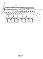
- the backlight module in this example is the same as that in Example 3 except that the deflection prism sheet assembly 6 and the collimating prism sheet 8 are integrated to generate a prism wedge 80.
- the third incident surface 81 is coincident with the third emergent surface 63.
- the collimating prism sheet 7 is employed to refract the emergent rays to be vertical to the liquid crystal display 1.
- the wedge sheet 4 can be rotated in a certain angle in advance, the second incident surface 62 is parallel to the second emergent surface 43 of the wedge sheet 4, so that the parallel beams from the fifth emergent surface 82 are vertical to the liquid crystal display 1.
- the backlight modules shown in FIGS. 12 and 13 have the same structures and functions. However, in FIG. 13 , the collimating prism sheet 8 is omitted, and thus the structure is much simple, thereby reducing the manufacturing difficulty and production costs.
Landscapes
- Physics & Mathematics (AREA)
- General Physics & Mathematics (AREA)
- Optics & Photonics (AREA)
- Nonlinear Science (AREA)
- Mathematical Physics (AREA)
- Chemical & Material Sciences (AREA)
- Crystallography & Structural Chemistry (AREA)
- Optical Elements Other Than Lenses (AREA)
- Planar Illumination Modules (AREA)
- Liquid Crystal (AREA)
Applications Claiming Priority (2)
| Application Number | Priority Date | Filing Date | Title |
|---|---|---|---|
| CN201210026819.6A CN102588835B (zh) | 2012-02-08 | 2012-02-08 | 一种用于液晶显示器的新型背光模组 |
| PCT/CN2012/001733 WO2013116970A1 (zh) | 2012-02-08 | 2012-12-26 | 一种用于液晶显示器的新型背光模组 |
Publications (2)
| Publication Number | Publication Date |
|---|---|
| EP2813751A1 true EP2813751A1 (de) | 2014-12-17 |
| EP2813751A4 EP2813751A4 (de) | 2015-10-14 |
Family
ID=46477871
Family Applications (1)
| Application Number | Title | Priority Date | Filing Date |
|---|---|---|---|
| EP12868306.7A Withdrawn EP2813751A4 (de) | 2012-02-08 | 2012-12-26 | Neuartiges rückbeleuchtungsmodul für flüssigkristallanzeige |
Country Status (6)
| Country | Link |
|---|---|
| US (1) | US9715141B2 (de) |
| EP (1) | EP2813751A4 (de) |
| JP (1) | JP6170072B2 (de) |
| KR (1) | KR20140138158A (de) |
| CN (1) | CN102588835B (de) |
| WO (1) | WO2013116970A1 (de) |
Families Citing this family (11)
| Publication number | Priority date | Publication date | Assignee | Title |
|---|---|---|---|---|
| CN102588835B (zh) * | 2012-02-08 | 2016-01-13 | 苏州晶智科技有限公司 | 一种用于液晶显示器的新型背光模组 |
| CN102681049B (zh) | 2012-03-12 | 2014-06-11 | 京东方科技集团股份有限公司 | 色偏平衡薄膜、侧入式背光模组及液晶显示装置 |
| CN103226261A (zh) * | 2013-03-26 | 2013-07-31 | 苏州晶智科技有限公司 | 一种用于液晶显示器的二维准直背光模组 |
| CN103235446B (zh) * | 2013-04-18 | 2016-04-27 | 中国科学院苏州纳米技术与纳米仿生研究所 | 一种用于液晶显示器的背光模组 |
| CN107515467B (zh) * | 2017-09-28 | 2021-01-15 | 厦门天马微电子有限公司 | 显示装置 |
| KR102525223B1 (ko) * | 2018-02-05 | 2023-04-25 | 삼성디스플레이 주식회사 | 백라이트 유닛 및 이를 포함하는 표시 장치 |
| CN109212660B (zh) * | 2018-10-26 | 2020-01-24 | 合肥京东方光电科技有限公司 | 导光组件、光准直组件、背光模组及显示装置 |
| TWI673517B (zh) * | 2018-12-20 | 2019-10-01 | 友達光電股份有限公司 | 光學調控元件以及顯示裝置 |
| CN111381398B (zh) * | 2018-12-29 | 2023-05-30 | 北京小米移动软件有限公司 | 显示模组及电子设备 |
| CN110208983B (zh) * | 2019-05-08 | 2022-02-18 | 马鞍山晶智科技有限公司 | 一种侧入式背光模组 |
| CN110032004B (zh) * | 2019-05-09 | 2021-09-07 | 马鞍山晶智科技有限公司 | 一种用于准直背光模组的楔形板及准直背光模组 |
Family Cites Families (25)
| Publication number | Priority date | Publication date | Assignee | Title |
|---|---|---|---|---|
| JPH065462B2 (ja) * | 1987-07-02 | 1994-01-19 | 信越ポリマ−株式会社 | バックライト装置 |
| JP3830982B2 (ja) * | 1994-03-31 | 2006-10-11 | 株式会社エンプラス | 楔形出射方向特性調整素子を用いた面光源装置 |
| US5521725A (en) * | 1993-11-05 | 1996-05-28 | Alliedsignal Inc. | Illumination system employing an array of microprisms |
| US5396350A (en) * | 1993-11-05 | 1995-03-07 | Alliedsignal Inc. | Backlighting apparatus employing an array of microprisms |
| US5838403A (en) * | 1996-02-14 | 1998-11-17 | Physical Optics Corporation | Liquid crystal display system with internally reflecting waveguide for backlighting and non-Lambertian diffusing |
| JPH09274184A (ja) * | 1996-04-04 | 1997-10-21 | Dainippon Printing Co Ltd | レンズフィルムおよびそれを用いた面光源装置 |
| JPH10246805A (ja) * | 1997-03-06 | 1998-09-14 | Dainippon Printing Co Ltd | 拡散光制御用光学シート、バックライト装置及び液晶表示装置 |
| JPH10253960A (ja) * | 1997-03-14 | 1998-09-25 | Enplas Corp | サイドライト型面光源装置及び光制御部材 |
| JP3852659B2 (ja) * | 1999-12-17 | 2006-12-06 | 株式会社エンプラス | 導光板、面光源装置及び液晶表示装置 |
| EP1329746B1 (de) * | 2000-10-19 | 2012-05-30 | Daicel Chemical Industries, Ltd. | Anisotropisch streuende folie und ihre verwendung |
| JP2003015133A (ja) * | 2001-04-27 | 2003-01-15 | Citizen Watch Co Ltd | 液晶表示装置 |
| TWI258023B (en) * | 2001-11-07 | 2006-07-11 | Ibm | A prism sheet, a back-light unit using said prism sheet, and a transmission type liquid crystal display device |
| US20060268418A1 (en) * | 2005-05-05 | 2006-11-30 | Kim Jong M | Optical films, method of making and method of using |
| KR100754400B1 (ko) * | 2006-04-21 | 2007-08-31 | 삼성전자주식회사 | 백라이트 유닛 및 이를 채용한 디스플레이 장치 |
| JP2007305543A (ja) * | 2006-05-15 | 2007-11-22 | Epson Imaging Devices Corp | 照明装置、電気光学装置、電子機器及び光学シート |
| JP2008034240A (ja) * | 2006-07-28 | 2008-02-14 | Citizen Electronics Co Ltd | バックライト |
| US8128257B2 (en) | 2007-02-09 | 2012-03-06 | Bright View Technologies Corporation | Curved compact collimating reflectors |
| TWM326642U (en) * | 2007-06-15 | 2008-02-01 | Jang Shiou Chin | Light guiding plate and liquid crystal display apparatus |
| CN101688991A (zh) * | 2007-06-22 | 2010-03-31 | 3M创新有限公司 | 控制背光源输出特性的系统和方法 |
| TW200900801A (en) * | 2007-06-29 | 2009-01-01 | Coretronic Corp | Backlight module and liquid crystal display having the same |
| CN101358711A (zh) * | 2007-08-01 | 2009-02-04 | 奇美电子股份有限公司 | 光源装置与平面显示器 |
| CN101609230B (zh) * | 2008-06-18 | 2011-12-14 | 鸿富锦精密工业(深圳)有限公司 | 背光模组 |
| JP5706332B2 (ja) * | 2008-11-19 | 2015-04-22 | スリーエム イノベイティブ プロパティズ カンパニー | 極方向及び方位方向の両方における出力制限を有する反射性フィルムの組み合わせ体並びに関連する構成 |
| CN102121621A (zh) * | 2010-01-08 | 2011-07-13 | 上海向隆电子科技有限公司 | 发光装置及使用该发光装置的电子书 |
| CN102588835B (zh) * | 2012-02-08 | 2016-01-13 | 苏州晶智科技有限公司 | 一种用于液晶显示器的新型背光模组 |
-
2012
- 2012-02-08 CN CN201210026819.6A patent/CN102588835B/zh active Active
- 2012-12-26 KR KR1020147025305A patent/KR20140138158A/ko not_active Ceased
- 2012-12-26 WO PCT/CN2012/001733 patent/WO2013116970A1/zh not_active Ceased
- 2012-12-26 JP JP2014555910A patent/JP6170072B2/ja active Active
- 2012-12-26 EP EP12868306.7A patent/EP2813751A4/de not_active Withdrawn
-
2014
- 2014-08-08 US US14/454,740 patent/US9715141B2/en active Active
Also Published As
| Publication number | Publication date |
|---|---|
| WO2013116970A1 (zh) | 2013-08-15 |
| US20140347602A1 (en) | 2014-11-27 |
| US9715141B2 (en) | 2017-07-25 |
| KR20140138158A (ko) | 2014-12-03 |
| CN102588835B (zh) | 2016-01-13 |
| CN102588835A (zh) | 2012-07-18 |
| JP2015513760A (ja) | 2015-05-14 |
| JP6170072B2 (ja) | 2017-07-26 |
| EP2813751A4 (de) | 2015-10-14 |
Similar Documents
| Publication | Publication Date | Title |
|---|---|---|
| EP2813751A1 (de) | Neuartiges rückbeleuchtungsmodul für flüssigkristallanzeige | |
| KR100903028B1 (ko) | 쐐기형 배면프리즘을 포함하는 액정표시장치 백라이트 유닛용 도광판 | |
| US8289639B2 (en) | Optical films | |
| JP4856261B2 (ja) | 光をコリメートする導光体、導光体のコリメーション改善方法、バックライト、及び表示装置 | |
| US9423553B2 (en) | Backlight device | |
| KR101528910B1 (ko) | 광학시트 및 이를 갖는 액정 표시장치 | |
| TW200408883A (en) | Polarized light source system and liquid crystal display using the same | |
| KR20030064258A (ko) | 도광판과 이를 구비한 광원 장치 및 표시 장치 | |
| CN106950641A (zh) | 一种导光板、光学模组及全反显示装置 | |
| CN101737725B (zh) | 背光模块及液晶显示器 | |
| US20110038177A1 (en) | Planar illumination device | |
| CN110389469A (zh) | 显示装置及其显示方法 | |
| CN103226261A (zh) | 一种用于液晶显示器的二维准直背光模组 | |
| US9140930B2 (en) | Slim frame backlight module | |
| US20130063976A1 (en) | Asymmetric serrated edge light guide film having circular base segments | |
| CN103235446B (zh) | 一种用于液晶显示器的背光模组 | |
| US7708445B2 (en) | Light guide device and backlight module using the same | |
| US20170003434A1 (en) | Backlight module and liquid crystal display | |
| CN219872040U (zh) | 一种准直背光模组 | |
| CN114755752B (zh) | 背光模组 | |
| CN104678650A (zh) | 背光模块 | |
| CN108873143A (zh) | 背光模组及其光源调整装置 | |
| US20250355158A1 (en) | Front light source module and display apparatus | |
| CN112764151B (zh) | 面光源装置和液晶显示装置 | |
| JP2006202559A (ja) | 面光源装置 |
Legal Events
| Date | Code | Title | Description |
|---|---|---|---|
| PUAI | Public reference made under article 153(3) epc to a published international application that has entered the european phase |
Free format text: ORIGINAL CODE: 0009012 |
|
| 17P | Request for examination filed |
Effective date: 20140905 |
|
| AK | Designated contracting states |
Kind code of ref document: A1 Designated state(s): AL AT BE BG CH CY CZ DE DK EE ES FI FR GB GR HR HU IE IS IT LI LT LU LV MC MK MT NL NO PL PT RO RS SE SI SK SM TR |
|
| AX | Request for extension of the european patent |
Extension state: BA ME |
|
| DAX | Request for extension of the european patent (deleted) | ||
| RA4 | Supplementary search report drawn up and despatched (corrected) |
Effective date: 20150914 |
|
| RIC1 | Information provided on ipc code assigned before grant |
Ipc: F21S 8/00 20060101AFI20150908BHEP Ipc: F21V 7/22 20060101ALI20150908BHEP Ipc: G02F 1/13357 20060101ALI20150908BHEP Ipc: F21V 5/02 20060101ALI20150908BHEP |
|
| STAA | Information on the status of an ep patent application or granted ep patent |
Free format text: STATUS: THE APPLICATION IS DEEMED TO BE WITHDRAWN |
|
| 18D | Application deemed to be withdrawn |
Effective date: 20160412 |