EP2813136B1 - Vorrichtung zur Dämpfung von Schwingungen in einer Schneidleiste mit Hin- und Herbewegung - Google Patents
Vorrichtung zur Dämpfung von Schwingungen in einer Schneidleiste mit Hin- und Herbewegung Download PDFInfo
- Publication number
- EP2813136B1 EP2813136B1 EP14170475.9A EP14170475A EP2813136B1 EP 2813136 B1 EP2813136 B1 EP 2813136B1 EP 14170475 A EP14170475 A EP 14170475A EP 2813136 B1 EP2813136 B1 EP 2813136B1
- Authority
- EP
- European Patent Office
- Prior art keywords
- movable blade
- motion
- crank
- kinematic
- blade
- Prior art date
- Legal status (The legal status is an assumption and is not a legal conclusion. Google has not performed a legal analysis and makes no representation as to the accuracy of the status listed.)
- Not-in-force
Links
- 230000033001 locomotion Effects 0.000 title claims description 52
- 238000005520 cutting process Methods 0.000 claims description 29
- 230000005540 biological transmission Effects 0.000 claims description 13
- 230000009466 transformation Effects 0.000 claims description 3
- 230000010355 oscillation Effects 0.000 claims 1
- 244000025254 Cannabis sativa Species 0.000 description 7
- 230000000694 effects Effects 0.000 description 6
- 230000007246 mechanism Effects 0.000 description 4
- 241000196324 Embryophyta Species 0.000 description 3
- 230000008878 coupling Effects 0.000 description 3
- 238000010168 coupling process Methods 0.000 description 3
- 238000005859 coupling reaction Methods 0.000 description 3
- 241001494496 Leersia Species 0.000 description 2
- 229910000831 Steel Inorganic materials 0.000 description 2
- 230000001133 acceleration Effects 0.000 description 2
- 230000009471 action Effects 0.000 description 2
- 230000008901 benefit Effects 0.000 description 2
- 239000003795 chemical substances by application Substances 0.000 description 2
- 238000005461 lubrication Methods 0.000 description 2
- 239000000203 mixture Substances 0.000 description 2
- 239000010959 steel Substances 0.000 description 2
- 235000019728 animal nutrition Nutrition 0.000 description 1
- 230000002547 anomalous effect Effects 0.000 description 1
- 238000005266 casting Methods 0.000 description 1
- 230000001427 coherent effect Effects 0.000 description 1
- 210000001520 comb Anatomy 0.000 description 1
- 230000006866 deterioration Effects 0.000 description 1
- 238000009792 diffusion process Methods 0.000 description 1
- 238000007599 discharging Methods 0.000 description 1
- 238000009826 distribution Methods 0.000 description 1
- 230000009977 dual effect Effects 0.000 description 1
- 238000000855 fermentation Methods 0.000 description 1
- 230000004151 fermentation Effects 0.000 description 1
- 238000009413 insulation Methods 0.000 description 1
- 239000000463 material Substances 0.000 description 1
- 238000000034 method Methods 0.000 description 1
- 230000003472 neutralizing effect Effects 0.000 description 1
- 239000000843 powder Substances 0.000 description 1
- 238000004321 preservation Methods 0.000 description 1
- 230000002035 prolonged effect Effects 0.000 description 1
- 210000002105 tongue Anatomy 0.000 description 1
Images





Classifications
-
- A—HUMAN NECESSITIES
- A01—AGRICULTURE; FORESTRY; ANIMAL HUSBANDRY; HUNTING; TRAPPING; FISHING
- A01D—HARVESTING; MOWING
- A01D34/00—Mowers; Mowing apparatus of harvesters
- A01D34/01—Mowers; Mowing apparatus of harvesters characterised by features relating to the type of cutting apparatus
- A01D34/02—Mowers; Mowing apparatus of harvesters characterised by features relating to the type of cutting apparatus having reciprocating cutters
- A01D34/30—Driving mechanisms for the cutters
- A01D34/305—Balancing
-
- A—HUMAN NECESSITIES
- A01—AGRICULTURE; FORESTRY; ANIMAL HUSBANDRY; HUNTING; TRAPPING; FISHING
- A01D—HARVESTING; MOWING
- A01D34/00—Mowers; Mowing apparatus of harvesters
- A01D34/01—Mowers; Mowing apparatus of harvesters characterised by features relating to the type of cutting apparatus
- A01D34/02—Mowers; Mowing apparatus of harvesters characterised by features relating to the type of cutting apparatus having reciprocating cutters
- A01D34/08—Mowers; Mowing apparatus of harvesters characterised by features relating to the type of cutting apparatus having reciprocating cutters hand-guided by a walking operator
Definitions
- the present invention relates to a device for abating the vibrations of a cutter bar with alternating motion.
- Cutting devices of this type are in fact assembled on most mowers adopted by the user on foot for cutting grass, fodder and plants in general in both the professional field and as a hobby.
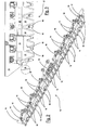
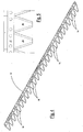
- Figures 1 to 5 show the state of the art for these devices and their application in a mower 11.
- current cutter bars 12 are composed of a structural supporting part 13, known in the field as “guide bar”, normally made of steel.
- This structural part 13 has a width equal to that to be cut and is made integral with the structure of the mower by means of a mechanical supporting and transmission group 20.
- a certain number of cutting elements or teeth 15, having a pointed triangular form, are rigidly fixed to this supporting part or guide bar 13, for example by means of bolts 14, and contribute to forming the so-called comb.
- the sharp edges can be equipped with prominent teeth 16 to accentuate the withholding of blades of grass during the cutting.
- a blade 17 rests on the above-mentioned plane thus defined, which is held in close contact with it by a series of rigid or elastic retainers called blade-holders 18.
- the blade 17 is normally made of steel and also has a certain number of cutting elements 19, or bladelets, having a triangular or trapezoidal shape with sharp cutting sides ( figure 4 ).
- a mechanical supporting and transmission group 20 ( figure 6 ), also normally moved by a motor 41 ( figure 1 ), generally endothermic, of the mower, contemporaneously carries the blade 17 and imparts an alternating movement with an appropriate frequency and amplitude to the same blade.
- Said mechanical supporting and transmission group 20 is rigidly connected to the guide bar 13 and connected to the blade 17 in the centre or at the sides with an articulated device 42 compatible with the transmission of the movement to be effected. In this way, the cutting bladelets 19 of the blade 17 pass alternatingly in correspondence with the spaces defined by the cutting elements 15 of the comb and effect the cutting with a procedure similar to that of scissors.
- This cutting device and relative supporting and transmission group work extremely well, but are not without problems.
- the blade 17 must be sufficiently robust as to be able to effect the cutting and resist any possible occasional and unexpected impact and stress. It must also be relatively insensitive to wear so as to ensure a sufficient duration and satisfactory preservation of the cutting edge with time.
- the cutter bar 12, and consequently the blade 17, must have a width which is coherent with the weight, power and preferential use of the mower 11 on which they must operate.
- Most professional or semi-professional mowers currently operate with bars having a weight ranging form 1 to 2 meters.
- the blade 17 is connected to the supporting and transmission group 20 of the motion which moves it by means of a robust and adequately structured mechanical connection.
- blades 17 having a significant mass, for example around 3 Kg per meter of width.
- a crucial parameter for obtaining this result is the relative velocity with which the cutting edge of the bladelets impacts the blades of grass forcing them against the cutting elements of the comb. Within certain limits, the greater this velocity, the better the cutting will be.
- the blade 17 must therefore move with an alternating motion with a high frequency, often in the order of 1,000 complete cycles per minute or even higher.
- the run For physical reasons linked to both the blade itself and to the vegetation to be cut, the run must be at least a few centimetres, typically reaching values ranging from 5 to 10 centimetres.
- Mowers which use these cutter bars are typically equipped with only two wheels 43 at the end of the same axis, having the cutter bar 12 at one end and the handlebars 44 at the opposite end.
- the alternating force of inertia produces a momentum that the very structure of the machine amplifies and transforms into vibrations having a high intensity.
- US 2 819 618 A is suitable only for lateral cutter bars. Moreover said device is largely open at the bottom and even completely open towards outside in its moving components, such as the mass of the counterweight, the components that determine the motion, the connecting and control rods of the cutter bar, etc.
- a general objective of the present invention is to solve the above-mentioned drawbacks of the known art in cutter bars, in an extremely simple, economical and particularly functional manner.
- a further objective of the present invention is to provide a device which is capable of eliminating or minimizing the inertial forces in a cutter bar of a mower during the operative movement of the cutting blade.
- Another objective of the present invention is to provide a device for abating the vibrations in a cutter bar with alternating motion which maintains an optimum cutting function.
- a mower 11 carries the cutter bar 12 by means of a supporting and transmission group of the motion 20.
- the blade 17 is ultimately connected to the transmission group 20 of the motion by means of a robust and adequately structured mechanical connection.
- the supporting and transmission group of the motion 20 of the blade 17 of the cutter bar 12 is constrained to the front part of the mower 11 by means of a support 45 positioned in correspondence with a power takeoff 46 produced by means of a rotating shaft.
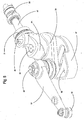
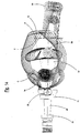
- the support 45 is in fact hollow, it is coupled with a carter 40 for the whole device, and a horizontal shaft 47 supported by bearings 21 and 22, passes through it.
- the shaft 47 carries a joint 23 at its free end towards the interior, whereby it is rotated by the power takeoff 46 of the mower 11.
- the shaft 47 comprises, on one of its flanged ends 48, an eccentric pin 24 which is engaged in a hole 53 of a cylindrical barrel cursor 25.
- the cylindrical barrel cursor 25 is free to slide vertically in a cylindrical seat 49 of an internal crank 26.
- the internal crank 26 is engaged, through a grooved coupling 27, with a lower end of a vertical shaft 28 supported by bearings 29 and 30 inside the carter 40, thus being able to oscillate around the shaft 28.
- Said vertical shaft 28 is engaged at the upper end, through a second grooved coupling 31, with a first end of an outer crank 32, which can therefore also oscillate around the shaft 28 like the internal crank 26.
- the outer crank 32 carries a hinged roll 33, whereby it is connected to the blade 17 and is engaged in an articulated device 42 constrained above the same blade ( figures 6-10 ).
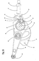
- a pass-through hole 36 whose upper end has an enlarged diameter in which there is an additional pin 34 which acts as a movable fulcrum.
- the additional pin 34 supports, by means of a pair of bearings 35, a balancing mass 37 which is free to oscillate.
- Said balancing mass 37 has an extension 38 at the rear, which is inserted in a cylindrical barrel cursor 39, which acts as a fixed fulcrum.
- the cylindrical barrel cursor 39 is free to slide vertically and rotate in a cylindrical seat 51 situated in the carter 40.
- This coupling allows both angular and axial movements between the parts and creates a further kinematic system for the alternating movement of the balancing mass 37 in a direction opposite to that of the movable blade 17, wherein this latter kinematic system is associated with and moved by the above-mentioned first kinematic system.
- the form of the balancing mass 37 is such that the barycentre is as close as possible to the blade 17 of the cutter bar 12, indicated for example in 52.
- the whole mechanism of the device is enclosed inside the casting of the supporting carter 40 which does not create any encumbrance.
- a possible encumbrance would in fact disturb the cutting and discharging of the grass, and the presence of this carter 40 maintains an indispensable lubrication and preserves the components from the action of contaminating agents.
- the position of the balancing mass 37 and the relative movement must satisfy some particular conditions.
- the mass 37 must be positioned as close as possible to the blade 17 so that the residual torque is minimum, due to the fact that the lines of action of the two forces of inertia are not perfecting coinciding.
- the movement of the balancing mass 37 must be as straight as possible, so as to generate a force of inertia as parallel as possible to the force of inertia due to the blade 17.
- the product of the mass for the run of the balancing mass must be as close as possible to the value of the same product between the mass and run of the blade.
- the movement of the barycentre is advantageously not circular as it derives from the composition of two opposed circular movements and this directs the trajectory towards a straight movement that would be optimum without there being any further complications in the mechanism.
- the motion of the barycentre 52 in figures 11 to 13 derives from the composition of two opposite arcs of circumference.
- Figure 14 shows the path of the trajectories as referred to above. Said figure 14 provides a clearer illustration of the fixed fulcrum 39 of the oscillating mass 37 and the movable fulcrum 34 which entrains the same oscillating mass 37.
- C indicates a trajectory with an arc of circumference of the same movable fulcrum 34.
- the barycentre 52 of the oscillating mass 37 would move around a line E (indicated by a dotted line) with a curved trajectory, if it were to simply oscillate around the fixed fulcrum 39.
- the trajectory of the barycentre 52 is indicated with the continuous line F created by the presence of the second kinematic system which is extremely close to an ideal straight trajectory indicated with G.
- the mass 37 oscillates around the fixed fulcrum 39 moved by the movable fulcrum 34 positioned on the internal crank 26.
- the distance between the two fulcra is much less than that between the fulcrum 39 and the barycentre 52 and creates a lever effect.
- the movement of the barycentre 52 is considerably amplified, as it can effect a significant increase in accelerations and consequently in the balancing inertial effect, even without using excessively high and encumbering masses 37.
- a second balancing mass 54 which can be positioned on the first internal crank 26 which contributes even more to eliminating the vibrations that can arise due to the motion inversions, increasing the benefits of the balancing mass 37 mentioned above positioned on the additional kinematic system.
- the present invention has identified a device which neutralizes the force which creates the vibratory motion, as it arises.
- the effect has therefore been obtained by using a mass having an appropriate value, which is moved in an alternating motion in counter-phase against the blade with an amplitude calculated so that most of the alternating forces of inertia are cancelled.
- the vibratory level is thus reduced on the handlebars, structures and driving controls with a marked increase in the ergonomics and ease of use. As the vibratory forces are cancelled at the source, the vibrations are reduced in the whole machine, protecting the mechanical components from stress which can jeopardize their reliability.
- the supporting functions of the bar, blade drive and movement of the balancing masses are advantageously integrated and contained in a single carter 40 having an adequate form with all the internal components in an oil bath.
- the resulting mechanism is suitable for professional use as it is airtight, insensitive to powder and contaminating agents typical of the environment of use.
- the constant lubrication improves the reliability of the mechanism and dissipation of the heat generated during functioning.
- the annulment at the source of the phenomenon makes the device suitable for all machine configurations which can have different mass distributions.
- the device itself must only be dimensioned in relation to the cutter bar that it must activate and can be designed for being adapted to a vast range of widths of the bar and consequently blade mass.
Landscapes
- Life Sciences & Earth Sciences (AREA)
- Environmental Sciences (AREA)
- Harvester Elements (AREA)
- Automatic Cycles, And Cycles In General (AREA)
Claims (3)
- Vorrichtung zum Dämpfen von Schwingungen in einem Schneidbalken (12) mit alternierender Bewegung, der mit einer Stütz- und Übertragungsgruppe (20) gekoppelt ist, die mit einem Zapfwellenantrieb (46) des Mähers (11) verbunden ist, wobei die Stütz- und Übertragungsgruppe (20) ein kinematisches Umwandlungssystem von einer Drehbewegung, die von dem Zapfwellenantrieb (46) kommt, in eine Bewegung der beweglichen Klinge (17), welche eben ist, mit einer alternierenden Bewegung in einer Querrichtung mit Bezug auf die Fortschrittsrichtung des Mähers und senkrecht zu einer Achse des Zapfwellenantriebs (46) umfasst, wobei die bewegliche Klinge in Eingriff an Schneidelementen (15) gehalten ist, die an der Stütz- und Übertragungsgruppe (20) festgespannt sind, wobei ein weiteres zweites kinematisches System dem ersten kinematischen Umwandlungssystem der Drehbewegung in eine ebene Bewegung mit einer alternierenden Bewegung der beweglichen Klinge (17) für die alternierende Hin- und Herbewegung einer Ausgleichsmasse (37) in einer entgegengesetzten Richtung zu der der beweglichen Klinge (17) zugeordnet ist, wobei das zweite weitere kinematische System durch das erste kinematische System bewegt wird, wobei sowohl das erste als auch das zweite kinematische System in einem einzigen Transporteur (40) in einem Ölbad enthalten sind, wobei der Zapfwellenantrieb (46) mittels eines Exzenterstifts (24) mit einem zylindrischen Sitz (49) einer Kurbel (26, 32) verbunden ist, von der ein freies Ende mit der beweglichen Klinge (17) drehbar verbunden ist (33, 42), wobei die oszillierende Masse (37) des zweiten kinematischen Systems (in 34) an einer Zwischenposition der Kurbel (26, 32) schwenkbar ist und an einem ihrer Enden um einen festen Drehpunkt (39) des Behältertransporteurs (40) herum eingespannt ist, dadurch gekennzeichnet, dass der feste Drehpunkt einen zylindrischen Trommelfinger (39) umfasst, der frei ist, um vertikal zu gleiten und in einem zylindrischen Sitz (51) zu rotieren, der in dem Transporteur (40) gelegen ist, und die Kurbel eine interne Kurbel (26) umfasst, die mit einer Welle (28) in Eingriff steht, die (in 29 und 30) im Inneren des Transporteurs (40) abgestützt ist, und eine äußere Kurbel (32), die auf einer Seite an der Welle (28) festgespannt ist und auf der anderen Seite mittels einer Rolle (33) mit einer angelenkten Einrichtung (42) verbunden ist, die oberhalb der beweglichen Klinge (17) festgespannt ist.
- Vorrichtung nach Anspruch 1, dadurch gekennzeichnet, dass die Ausgleichsmasse (37) eine Form aufweist, die derart ist, dass sie einen Schwerpunkt (52) so nahe wie möglich bei der beweglichen Klinge (17) des Schneidbalkens (12) aufweist.
- Vorrichtung nach Anspruch 2, dadurch gekennzeichnet, dass der Schwerpunkt (52) der Ausgleichsmasse (37) während ihrer Oszillation einer im Wesentlichen geraden Bahn folgt.
Applications Claiming Priority (1)
| Application Number | Priority Date | Filing Date | Title |
|---|---|---|---|
| IT000969A ITMI20130969A1 (it) | 2013-06-13 | 2013-06-13 | Dispositivo per l'abbattimento delle vibrazioni in una barra falciante a moto alternato |
Publications (2)
| Publication Number | Publication Date |
|---|---|
| EP2813136A1 EP2813136A1 (de) | 2014-12-17 |
| EP2813136B1 true EP2813136B1 (de) | 2018-03-21 |
Family
ID=49000537
Family Applications (1)
| Application Number | Title | Priority Date | Filing Date |
|---|---|---|---|
| EP14170475.9A Not-in-force EP2813136B1 (de) | 2013-06-13 | 2014-05-29 | Vorrichtung zur Dämpfung von Schwingungen in einer Schneidleiste mit Hin- und Herbewegung |
Country Status (3)
| Country | Link |
|---|---|
| EP (1) | EP2813136B1 (de) |
| CN (1) | CN104221576B (de) |
| IT (1) | ITMI20130969A1 (de) |
Families Citing this family (9)
| Publication number | Priority date | Publication date | Assignee | Title |
|---|---|---|---|---|
| CN104996063A (zh) * | 2015-07-17 | 2015-10-28 | 重庆嘉木机械有限公司 | 一种剪草-微耕两用机剪刀开合驱动结构 |
| CN105052354A (zh) * | 2015-07-17 | 2015-11-18 | 重庆嘉木机械有限公司 | 一种农用多功能机剪刀开合驱动机构 |
| CN106105544B (zh) * | 2016-08-26 | 2018-03-02 | 浙江乐客来机械有限公司 | 粗割机器 |
| CN106171256B (zh) * | 2016-08-26 | 2018-03-13 | 浙江乐客来机械有限公司 | 横行粗割机器 |
| CN106068893B (zh) * | 2016-08-26 | 2018-03-02 | 浙江乐客来机械有限公司 | 一种横行粗割机器 |
| CN106171251B (zh) * | 2016-08-26 | 2018-03-30 | 浙江乐客来机械有限公司 | 一种横行粗割机 |
| CN106385941A (zh) * | 2016-11-04 | 2017-02-15 | 成都森钰泓绿化工程有限公司 | 一种用于修剪绿化草坪手推排式修剪机 |
| CN106385940A (zh) * | 2016-11-04 | 2017-02-15 | 成都森钰泓绿化工程有限公司 | 一种手持排式割草机 |
| CN117337999A (zh) * | 2023-08-15 | 2024-01-05 | 潍坊市农业科学院(山东省农业科学院潍坊市分院) | 一种姜汁压榨设备及压榨方法 |
Citations (1)
| Publication number | Priority date | Publication date | Assignee | Title |
|---|---|---|---|---|
| EP0035805A2 (de) * | 1980-02-20 | 1981-09-16 | Officine Meccaniche Ferrari Fernando S.p.A. | Gelenk für Mähschwinge |
Family Cites Families (9)
| Publication number | Priority date | Publication date | Assignee | Title |
|---|---|---|---|---|
| US2819618A (en) * | 1953-05-04 | 1958-01-14 | Slusher Frank | Counterbalancing apparatus for reciprocating slide |
| US2769297A (en) * | 1953-08-13 | 1956-11-06 | Int Harvester Co | Balanced mower |
| US2808696A (en) * | 1954-10-26 | 1957-10-08 | Int Harvester Co | Counterbalanced drive mechanism for harvester sickles |
| GB1447441A (en) * | 1974-01-02 | 1976-08-25 | Heath H C | Counterbalanced twin knife mower |
| AT403336B (de) * | 1996-07-18 | 1998-01-26 | Bauer & Co Gmbh Reform Werke | Handgeführte, selbstfahrende arbeitsmaschine |
| US6314707B1 (en) * | 2000-01-06 | 2001-11-13 | Cyril A. Ryan | Balanced reciprocating, brush cutting, mower attachment |
| CN2676593Y (zh) * | 2003-10-24 | 2005-02-09 | 李晋全 | 半封闭脱谷滚筒联合收割机 |
| US7121074B1 (en) * | 2005-05-31 | 2006-10-17 | Acco Corporation | Balanced epicyclic sickle drive |
| US8011272B1 (en) * | 2010-04-28 | 2011-09-06 | Cnh America Llc | Dual flywheel axially compact epicyclical drive |
-
2013
- 2013-06-13 IT IT000969A patent/ITMI20130969A1/it unknown
-
2014
- 2014-05-29 EP EP14170475.9A patent/EP2813136B1/de not_active Not-in-force
- 2014-06-13 CN CN201410419053.7A patent/CN104221576B/zh not_active Expired - Fee Related
Patent Citations (1)
| Publication number | Priority date | Publication date | Assignee | Title |
|---|---|---|---|---|
| EP0035805A2 (de) * | 1980-02-20 | 1981-09-16 | Officine Meccaniche Ferrari Fernando S.p.A. | Gelenk für Mähschwinge |
Also Published As
| Publication number | Publication date |
|---|---|
| EP2813136A1 (de) | 2014-12-17 |
| CN104221576A (zh) | 2014-12-24 |
| CN104221576B (zh) | 2016-10-26 |
| ITMI20130969A1 (it) | 2014-12-14 |
Similar Documents
| Publication | Publication Date | Title |
|---|---|---|
| EP2813136B1 (de) | Vorrichtung zur Dämpfung von Schwingungen in einer Schneidleiste mit Hin- und Herbewegung | |
| JP7610453B2 (ja) | 園芸用トリマ | |
| EP3563656A1 (de) | Schneidmesser und rasenmäher | |
| JP6310646B2 (ja) | 刈払い機の草切断ブレード | |
| US6314707B1 (en) | Balanced reciprocating, brush cutting, mower attachment | |
| JP2023014527A (ja) | 刈込機 | |
| US20120198709A1 (en) | Oscillating blade improvement | |
| CN108055909B (zh) | 一种步行式割草机 | |
| CN114711013A (zh) | 剪断机构 | |
| KR101986103B1 (ko) | 풀 예취 장치 | |
| JP6918336B2 (ja) | 草刈り機 | |
| WO2025089067A1 (ja) | レシプロ式刈刃装置及び刈刃ユニット | |
| ITRM20060268A1 (it) | Dispositivo trinciatore in particolare per macchine agricole | |
| JP5371861B2 (ja) | 歩行型作業機 | |
| JP7045678B2 (ja) | 草刈剪定機 | |
| US12041873B2 (en) | Finger-bar-type mower with center drive | |
| US3436901A (en) | Cutting machine for stalk corps | |
| KR102612107B1 (ko) | 주행방향과 평행한 제초날 회전축을 가진 중경 제초기 | |
| KR20160092268A (ko) | 자주식 차량에 탈부착 가능하게 결합되는 제초 장치 | |
| US3017736A (en) | Double sickle mower construction | |
| KR101757868B1 (ko) | 예초기용 칼날 | |
| CN113939184B (zh) | 往复移动割刀式手持作业机 | |
| KR101734658B1 (ko) | 예초기 | |
| EP2529611A1 (de) | Schneidgerät | |
| JP3016184B2 (ja) | 二輪式両面裾刈機 |
Legal Events
| Date | Code | Title | Description |
|---|---|---|---|
| 17P | Request for examination filed |
Effective date: 20140529 |
|
| AK | Designated contracting states |
Kind code of ref document: A1 Designated state(s): AL AT BE BG CH CY CZ DE DK EE ES FI FR GB GR HR HU IE IS IT LI LT LU LV MC MK MT NL NO PL PT RO RS SE SI SK SM TR |
|
| AX | Request for extension of the european patent |
Extension state: BA ME |
|
| PUAI | Public reference made under article 153(3) epc to a published international application that has entered the european phase |
Free format text: ORIGINAL CODE: 0009012 |
|
| R17P | Request for examination filed (corrected) |
Effective date: 20150529 |
|
| RBV | Designated contracting states (corrected) |
Designated state(s): AL AT BE BG CH CY CZ DE DK EE ES FI FR GB GR HR HU IE IS IT LI LT LU LV MC MK MT NL NO PL PT RO RS SE SI SK SM TR |
|
| 17Q | First examination report despatched |
Effective date: 20170714 |
|
| GRAP | Despatch of communication of intention to grant a patent |
Free format text: ORIGINAL CODE: EPIDOSNIGR1 |
|
| INTG | Intention to grant announced |
Effective date: 20171110 |
|
| GRAS | Grant fee paid |
Free format text: ORIGINAL CODE: EPIDOSNIGR3 |
|
| GRAA | (expected) grant |
Free format text: ORIGINAL CODE: 0009210 |
|
| AK | Designated contracting states |
Kind code of ref document: B1 Designated state(s): AL AT BE BG CH CY CZ DE DK EE ES FI FR GB GR HR HU IE IS IT LI LT LU LV MC MK MT NL NO PL PT RO RS SE SI SK SM TR |
|
| REG | Reference to a national code |
Ref country code: GB Ref legal event code: FG4D |
|
| REG | Reference to a national code |
Ref country code: CH Ref legal event code: EP |
|
| REG | Reference to a national code |
Ref country code: AT Ref legal event code: REF Ref document number: 980074 Country of ref document: AT Kind code of ref document: T Effective date: 20180415 |
|
| REG | Reference to a national code |
Ref country code: IE Ref legal event code: FG4D |
|
| REG | Reference to a national code |
Ref country code: DE Ref legal event code: R096 Ref document number: 602014022506 Country of ref document: DE |
|
| REG | Reference to a national code |
Ref country code: NL Ref legal event code: MP Effective date: 20180321 |
|
| PG25 | Lapsed in a contracting state [announced via postgrant information from national office to epo] |
Ref country code: NO Free format text: LAPSE BECAUSE OF FAILURE TO SUBMIT A TRANSLATION OF THE DESCRIPTION OR TO PAY THE FEE WITHIN THE PRESCRIBED TIME-LIMIT Effective date: 20180621 Ref country code: FI Free format text: LAPSE BECAUSE OF FAILURE TO SUBMIT A TRANSLATION OF THE DESCRIPTION OR TO PAY THE FEE WITHIN THE PRESCRIBED TIME-LIMIT Effective date: 20180321 Ref country code: CY Free format text: LAPSE BECAUSE OF FAILURE TO SUBMIT A TRANSLATION OF THE DESCRIPTION OR TO PAY THE FEE WITHIN THE PRESCRIBED TIME-LIMIT Effective date: 20180321 Ref country code: HR Free format text: LAPSE BECAUSE OF FAILURE TO SUBMIT A TRANSLATION OF THE DESCRIPTION OR TO PAY THE FEE WITHIN THE PRESCRIBED TIME-LIMIT Effective date: 20180321 Ref country code: LT Free format text: LAPSE BECAUSE OF FAILURE TO SUBMIT A TRANSLATION OF THE DESCRIPTION OR TO PAY THE FEE WITHIN THE PRESCRIBED TIME-LIMIT Effective date: 20180321 |
|
| REG | Reference to a national code |
Ref country code: LT Ref legal event code: MG4D |
|
| REG | Reference to a national code |
Ref country code: AT Ref legal event code: MK05 Ref document number: 980074 Country of ref document: AT Kind code of ref document: T Effective date: 20180321 |
|
| PG25 | Lapsed in a contracting state [announced via postgrant information from national office to epo] |
Ref country code: RS Free format text: LAPSE BECAUSE OF FAILURE TO SUBMIT A TRANSLATION OF THE DESCRIPTION OR TO PAY THE FEE WITHIN THE PRESCRIBED TIME-LIMIT Effective date: 20180321 Ref country code: BG Free format text: LAPSE BECAUSE OF FAILURE TO SUBMIT A TRANSLATION OF THE DESCRIPTION OR TO PAY THE FEE WITHIN THE PRESCRIBED TIME-LIMIT Effective date: 20180621 Ref country code: LV Free format text: LAPSE BECAUSE OF FAILURE TO SUBMIT A TRANSLATION OF THE DESCRIPTION OR TO PAY THE FEE WITHIN THE PRESCRIBED TIME-LIMIT Effective date: 20180321 Ref country code: SE Free format text: LAPSE BECAUSE OF FAILURE TO SUBMIT A TRANSLATION OF THE DESCRIPTION OR TO PAY THE FEE WITHIN THE PRESCRIBED TIME-LIMIT Effective date: 20180321 Ref country code: GR Free format text: LAPSE BECAUSE OF FAILURE TO SUBMIT A TRANSLATION OF THE DESCRIPTION OR TO PAY THE FEE WITHIN THE PRESCRIBED TIME-LIMIT Effective date: 20180622 |
|
| PG25 | Lapsed in a contracting state [announced via postgrant information from national office to epo] |
Ref country code: EE Free format text: LAPSE BECAUSE OF FAILURE TO SUBMIT A TRANSLATION OF THE DESCRIPTION OR TO PAY THE FEE WITHIN THE PRESCRIBED TIME-LIMIT Effective date: 20180321 Ref country code: PL Free format text: LAPSE BECAUSE OF FAILURE TO SUBMIT A TRANSLATION OF THE DESCRIPTION OR TO PAY THE FEE WITHIN THE PRESCRIBED TIME-LIMIT Effective date: 20180321 Ref country code: ES Free format text: LAPSE BECAUSE OF FAILURE TO SUBMIT A TRANSLATION OF THE DESCRIPTION OR TO PAY THE FEE WITHIN THE PRESCRIBED TIME-LIMIT Effective date: 20180321 Ref country code: NL Free format text: LAPSE BECAUSE OF FAILURE TO SUBMIT A TRANSLATION OF THE DESCRIPTION OR TO PAY THE FEE WITHIN THE PRESCRIBED TIME-LIMIT Effective date: 20180321 Ref country code: RO Free format text: LAPSE BECAUSE OF FAILURE TO SUBMIT A TRANSLATION OF THE DESCRIPTION OR TO PAY THE FEE WITHIN THE PRESCRIBED TIME-LIMIT Effective date: 20180321 Ref country code: IT Free format text: LAPSE BECAUSE OF FAILURE TO SUBMIT A TRANSLATION OF THE DESCRIPTION OR TO PAY THE FEE WITHIN THE PRESCRIBED TIME-LIMIT Effective date: 20180321 Ref country code: AL Free format text: LAPSE BECAUSE OF FAILURE TO SUBMIT A TRANSLATION OF THE DESCRIPTION OR TO PAY THE FEE WITHIN THE PRESCRIBED TIME-LIMIT Effective date: 20180321 |
|
| PG25 | Lapsed in a contracting state [announced via postgrant information from national office to epo] |
Ref country code: CZ Free format text: LAPSE BECAUSE OF FAILURE TO SUBMIT A TRANSLATION OF THE DESCRIPTION OR TO PAY THE FEE WITHIN THE PRESCRIBED TIME-LIMIT Effective date: 20180321 Ref country code: SK Free format text: LAPSE BECAUSE OF FAILURE TO SUBMIT A TRANSLATION OF THE DESCRIPTION OR TO PAY THE FEE WITHIN THE PRESCRIBED TIME-LIMIT Effective date: 20180321 Ref country code: SM Free format text: LAPSE BECAUSE OF FAILURE TO SUBMIT A TRANSLATION OF THE DESCRIPTION OR TO PAY THE FEE WITHIN THE PRESCRIBED TIME-LIMIT Effective date: 20180321 Ref country code: AT Free format text: LAPSE BECAUSE OF FAILURE TO SUBMIT A TRANSLATION OF THE DESCRIPTION OR TO PAY THE FEE WITHIN THE PRESCRIBED TIME-LIMIT Effective date: 20180321 |
|
| REG | Reference to a national code |
Ref country code: DE Ref legal event code: R119 Ref document number: 602014022506 Country of ref document: DE |
|
| REG | Reference to a national code |
Ref country code: CH Ref legal event code: PL |
|
| PG25 | Lapsed in a contracting state [announced via postgrant information from national office to epo] |
Ref country code: PT Free format text: LAPSE BECAUSE OF FAILURE TO SUBMIT A TRANSLATION OF THE DESCRIPTION OR TO PAY THE FEE WITHIN THE PRESCRIBED TIME-LIMIT Effective date: 20180723 |
|
| PLBE | No opposition filed within time limit |
Free format text: ORIGINAL CODE: 0009261 |
|
| STAA | Information on the status of an ep patent application or granted ep patent |
Free format text: STATUS: NO OPPOSITION FILED WITHIN TIME LIMIT |
|
| REG | Reference to a national code |
Ref country code: BE Ref legal event code: MM Effective date: 20180531 |
|
| PG25 | Lapsed in a contracting state [announced via postgrant information from national office to epo] |
Ref country code: MC Free format text: LAPSE BECAUSE OF FAILURE TO SUBMIT A TRANSLATION OF THE DESCRIPTION OR TO PAY THE FEE WITHIN THE PRESCRIBED TIME-LIMIT Effective date: 20180321 Ref country code: DK Free format text: LAPSE BECAUSE OF FAILURE TO SUBMIT A TRANSLATION OF THE DESCRIPTION OR TO PAY THE FEE WITHIN THE PRESCRIBED TIME-LIMIT Effective date: 20180321 |
|
| REG | Reference to a national code |
Ref country code: IE Ref legal event code: MM4A |
|
| 26N | No opposition filed |
Effective date: 20190102 |
|
| GBPC | Gb: european patent ceased through non-payment of renewal fee |
Effective date: 20180621 |
|
| PG25 | Lapsed in a contracting state [announced via postgrant information from national office to epo] |
Ref country code: CH Free format text: LAPSE BECAUSE OF NON-PAYMENT OF DUE FEES Effective date: 20180531 Ref country code: LI Free format text: LAPSE BECAUSE OF NON-PAYMENT OF DUE FEES Effective date: 20180531 |
|
| PG25 | Lapsed in a contracting state [announced via postgrant information from national office to epo] |
Ref country code: LU Free format text: LAPSE BECAUSE OF NON-PAYMENT OF DUE FEES Effective date: 20180529 |
|
| PG25 | Lapsed in a contracting state [announced via postgrant information from national office to epo] |
Ref country code: GB Free format text: LAPSE BECAUSE OF NON-PAYMENT OF DUE FEES Effective date: 20180621 Ref country code: FR Free format text: LAPSE BECAUSE OF NON-PAYMENT OF DUE FEES Effective date: 20180531 Ref country code: DE Free format text: LAPSE BECAUSE OF NON-PAYMENT OF DUE FEES Effective date: 20181201 Ref country code: IE Free format text: LAPSE BECAUSE OF NON-PAYMENT OF DUE FEES Effective date: 20180529 |
|
| PG25 | Lapsed in a contracting state [announced via postgrant information from national office to epo] |
Ref country code: BE Free format text: LAPSE BECAUSE OF NON-PAYMENT OF DUE FEES Effective date: 20180531 Ref country code: SI Free format text: LAPSE BECAUSE OF FAILURE TO SUBMIT A TRANSLATION OF THE DESCRIPTION OR TO PAY THE FEE WITHIN THE PRESCRIBED TIME-LIMIT Effective date: 20180321 |
|
| PG25 | Lapsed in a contracting state [announced via postgrant information from national office to epo] |
Ref country code: MT Free format text: LAPSE BECAUSE OF NON-PAYMENT OF DUE FEES Effective date: 20180529 |
|
| PG25 | Lapsed in a contracting state [announced via postgrant information from national office to epo] |
Ref country code: TR Free format text: LAPSE BECAUSE OF FAILURE TO SUBMIT A TRANSLATION OF THE DESCRIPTION OR TO PAY THE FEE WITHIN THE PRESCRIBED TIME-LIMIT Effective date: 20180321 |
|
| PG25 | Lapsed in a contracting state [announced via postgrant information from national office to epo] |
Ref country code: HU Free format text: LAPSE BECAUSE OF FAILURE TO SUBMIT A TRANSLATION OF THE DESCRIPTION OR TO PAY THE FEE WITHIN THE PRESCRIBED TIME-LIMIT; INVALID AB INITIO Effective date: 20140529 |
|
| PG25 | Lapsed in a contracting state [announced via postgrant information from national office to epo] |
Ref country code: MK Free format text: LAPSE BECAUSE OF NON-PAYMENT OF DUE FEES Effective date: 20180321 |
|
| PG25 | Lapsed in a contracting state [announced via postgrant information from national office to epo] |
Ref country code: IS Free format text: LAPSE BECAUSE OF FAILURE TO SUBMIT A TRANSLATION OF THE DESCRIPTION OR TO PAY THE FEE WITHIN THE PRESCRIBED TIME-LIMIT Effective date: 20180721 |