EP2812723B2 - Anordnung an einem bauteil eines kraftfahrzeuges - Google Patents
Anordnung an einem bauteil eines kraftfahrzeuges Download PDFInfo
- Publication number
- EP2812723B2 EP2812723B2 EP13701107.8A EP13701107A EP2812723B2 EP 2812723 B2 EP2812723 B2 EP 2812723B2 EP 13701107 A EP13701107 A EP 13701107A EP 2812723 B2 EP2812723 B2 EP 2812723B2
- Authority
- EP
- European Patent Office
- Prior art keywords
- component
- sensor
- sealing ring
- ring
- ring element
- Prior art date
- Legal status (The legal status is an assumption and is not a legal conclusion. Google has not performed a legal analysis and makes no representation as to the accuracy of the status listed.)
- Active
Links
Images


Classifications
-
- G—PHYSICS
- G01—MEASURING; TESTING
- G01S—RADIO DIRECTION-FINDING; RADIO NAVIGATION; DETERMINING DISTANCE OR VELOCITY BY USE OF RADIO WAVES; LOCATING OR PRESENCE-DETECTING BY USE OF THE REFLECTION OR RERADIATION OF RADIO WAVES; ANALOGOUS ARRANGEMENTS USING OTHER WAVES
- G01S7/00—Details of systems according to groups G01S13/00, G01S15/00, G01S17/00
- G01S7/52—Details of systems according to groups G01S13/00, G01S15/00, G01S17/00 of systems according to group G01S15/00
-
- B—PERFORMING OPERATIONS; TRANSPORTING
- B60—VEHICLES IN GENERAL
- B60R—VEHICLES, VEHICLE FITTINGS, OR VEHICLE PARTS, NOT OTHERWISE PROVIDED FOR
- B60R19/00—Wheel guards; Radiator guards, e.g. grilles; Obstruction removers; Fittings damping bouncing force in collisions
- B60R19/02—Bumpers, i.e. impact receiving or absorbing members for protecting vehicles or fending off blows from other vehicles or objects
- B60R19/48—Bumpers, i.e. impact receiving or absorbing members for protecting vehicles or fending off blows from other vehicles or objects combined with, or convertible into, other devices or objects, e.g. bumpers combined with road brushes, bumpers convertible into beds
- B60R19/483—Bumpers, i.e. impact receiving or absorbing members for protecting vehicles or fending off blows from other vehicles or objects combined with, or convertible into, other devices or objects, e.g. bumpers combined with road brushes, bumpers convertible into beds with obstacle sensors of electric or electronic type
-
- G—PHYSICS
- G01—MEASURING; TESTING
- G01S—RADIO DIRECTION-FINDING; RADIO NAVIGATION; DETERMINING DISTANCE OR VELOCITY BY USE OF RADIO WAVES; LOCATING OR PRESENCE-DETECTING BY USE OF THE REFLECTION OR RERADIATION OF RADIO WAVES; ANALOGOUS ARRANGEMENTS USING OTHER WAVES
- G01S15/00—Systems using the reflection or reradiation of acoustic waves, e.g. sonar systems
- G01S15/88—Sonar systems specially adapted for specific applications
- G01S15/93—Sonar systems specially adapted for specific applications for anti-collision purposes
- G01S15/931—Sonar systems specially adapted for specific applications for anti-collision purposes of land vehicles
-
- G—PHYSICS
- G01—MEASURING; TESTING
- G01S—RADIO DIRECTION-FINDING; RADIO NAVIGATION; DETERMINING DISTANCE OR VELOCITY BY USE OF RADIO WAVES; LOCATING OR PRESENCE-DETECTING BY USE OF THE REFLECTION OR RERADIATION OF RADIO WAVES; ANALOGOUS ARRANGEMENTS USING OTHER WAVES
- G01S7/00—Details of systems according to groups G01S13/00, G01S15/00, G01S17/00
- G01S7/52—Details of systems according to groups G01S13/00, G01S15/00, G01S17/00 of systems according to group G01S15/00
- G01S7/521—Constructional features
-
- G—PHYSICS
- G10—MUSICAL INSTRUMENTS; ACOUSTICS
- G10K—SOUND-PRODUCING DEVICES; METHODS OR DEVICES FOR PROTECTING AGAINST, OR FOR DAMPING, NOISE OR OTHER ACOUSTIC WAVES IN GENERAL; ACOUSTICS NOT OTHERWISE PROVIDED FOR
- G10K11/00—Methods or devices for transmitting, conducting or directing sound in general; Methods or devices for protecting against, or for damping, noise or other acoustic waves in general
-
- G—PHYSICS
- G01—MEASURING; TESTING
- G01S—RADIO DIRECTION-FINDING; RADIO NAVIGATION; DETERMINING DISTANCE OR VELOCITY BY USE OF RADIO WAVES; LOCATING OR PRESENCE-DETECTING BY USE OF THE REFLECTION OR RERADIATION OF RADIO WAVES; ANALOGOUS ARRANGEMENTS USING OTHER WAVES
- G01S15/00—Systems using the reflection or reradiation of acoustic waves, e.g. sonar systems
- G01S15/88—Sonar systems specially adapted for specific applications
- G01S15/93—Sonar systems specially adapted for specific applications for anti-collision purposes
- G01S15/931—Sonar systems specially adapted for specific applications for anti-collision purposes of land vehicles
- G01S2015/937—Sonar systems specially adapted for specific applications for anti-collision purposes of land vehicles sensor installation details
- G01S2015/938—Sonar systems specially adapted for specific applications for anti-collision purposes of land vehicles sensor installation details in the bumper area
Definitions
- the invention relates to an arrangement on a component of a motor vehicle, consisting of a sensor with a substantially flat front surface, a sealing ring surrounding the sensor and a carrier element for keeping the sensor at a distance in the axial direction relative to the component, the sensor being connected to the sealing ring in such a way that a recess of the component extends such that the end face of the sensor essentially forms a plane with an outside of the component.
- sensors in the outer skin of vehicles. With such sensors, the environment is detected and objects or obstacles are recognized.
- sensors can be ultrasonic sensors that are used for parking assistance systems.
- Such sensors are acoustically decoupled from the component or the structure in which they are installed by a decoupling part, so that vibrations that occur are not transmitted from the sensor to the component and from the component to the sensor.
- a seal should be provided between the sensor and the component to prevent the ingress of liquid, usually water, into the recess of the component.
- these sensors have a circular cross-section and the decoupling or sealing parts have an annular cross-section.
- Known solutions use a so-called decoupling ring to achieve both goals.
- Ultrasonic sensors emit ultrasonic signals that are reflected by an object or obstacle in the transmission range and are received by the same or by other ultrasonic transducers. For this reason, it is important that the membrane on the face of the sensor can vibrate freely. Therefore, a ring-shaped decoupling part is used to acoustically isolate the membrane from the installation environment, the component. In the case of an undesired acoustic coupling between the sensor and the component, the sensor no longer fulfills its function correctly and the coupled-in sound can stimulate the membrane again or be radiated backwards into the component. Such a situation can occur when ingressed water freezes and forms an acoustic bridge. This can lead to received vibrations being incorrectly recognized.
- decoupling rings which have a circumferential bead. As described above, with these decoupling rings it can happen that water entering under pressure does not drain off quickly enough and can freeze at low temperatures, thus reducing the effectiveness of the decoupling ring, since the solid ice creates an acoustic connection between the sensor and the sensor Component can come, whereby unwanted vibrations between the sensor are transmitted to the component.
- the sealing ring with circumferential bead If the sealing ring with circumferential bead is subjected to pressurized water, the water that hits it can penetrate between the component and the sealing ring. Remaining water can freeze quickly and lead to the emitted sound being coupled into the installation environment, for example the vehicle bumper. This disrupts the sensor and can lead to the detection of apparent obstacles.
- a component of a motor vehicle consisting of a sensor with a substantially flat end face, a sealing ring enclosing the sensor and a carrier element for keeping the sensor at a distance in the axial direction relative to the component, the sensor with the sealing ring being in such a way in a Recess of the component extends that the end face of the sensor and an outer side of the component essentially form a plane.
- the sensor is preferably an ultrasonic sensor.
- the surface of the sealing ring has a strip-shaped indentation at at least one point, so that the surface of the sealing ring is set back in relation to the surface of the sensor in this area.
- An arrangement according to the invention comprises a component, for example a bumper of a motor vehicle, and a sensor which is arranged in a cutout of the component, the end face of the sensor essentially forming a plane with the component.
- the sensor arranged on the component is in particular an ultrasonic sensor and part of a driver assistance system of a motor vehicle.
- the senor comprises a sealing ring which also extends into the recess of the component.
- the sealing ring serves in particular to seal the sensor from the component.
- An additional task of the sealing ring is the mechanical and acoustic decoupling of the sensor from the component.
- the sealing ring surrounding the sensor has an additional ring element which is located further outside in the radial direction and has at least two recesses distributed over the circumference.
- the ring element is designed in such a way that water penetrating can run off via the recesses.
- the ring element lying on the outside consists of a plurality of sections arranged in the shape of a ring.
- the end face of the outer ring element is in contact with the inside or face of the component.
- the outer ring element is connected to the sealing ring via webs on its inner side.
- the sealing ring and the outer ring element are designed in one piece.
- the sealing ring preferably forms a hollow-cylindrical partial area with the outer ring element, with lamellae and/or knobs being arranged in the circumferential direction on the outer ring element in addition to the webs.
- the lamellae can be designed in the form of rectangular ribs, the longitudinal side of which runs in the radial direction of the hollow cylinder.
- a circumferential, internal ring of knobs or columns with a circular cross section can also be formed.
- the webs and/or lamellae and/or nubs according to the invention are used to hold the outer ring element in a fixed position and thus to ensure the seal between the sensor and the component.
- the sealing ring is designed at the same time as a decoupling ring.
- the sealing ring and/or the ring element preferably consists of a polymer, preferably a silicone.
- the ring element of the sealing ring or decoupling ring according to the invention serves to seal against water penetrating from the outside and to ensure correct self-positioning of the sensor in the recess of the component.
- the recesses according to the invention in the outer ring element allow water that has entered to drain off.
- the ring element is designed to be elastic in order to compensate for tolerances in the axial direction between the sensor, the component and the carrier element.
- the tolerances can be caused, for example, by irregularities in the connections between the carrier element and the component or by tolerances in the carrier element itself.
- a further advantage of the embodiment of the sealing ring according to the invention is that the material consumption and the weight can be kept low.
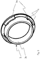
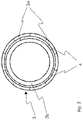
- the sealing ring 3 which also serves as a decoupling ring, is in 1 and 2 shown. It consists of a hollow-cylindrical body 3b with an outer and spaced ring element 3a. This outer ring element 3a has a plurality of recesses distributed over its circumference. The outer ring element also has stabilizing lamellae, nubs and/or webs on its inside, which can optionally also be connected to the hollow-cylindrical body 3b of the sealing ring. In the embodiment of 1 the outer ring element 3a consists of four partial sections distributed over the circumference, each of which has two webs 4 for stabilization. The embodiment in 2 shows a ring element 3b with five arranged sections, each with a web per section.
- the component 2 of 3 and 4 runs parallel to a plane which is perpendicular to the axial direction A.
- the axial direction A coincides with the axis of rotation of a sensor 1 which is of essentially rotationally symmetrical design.
- the sensor 1 includes, in particular, a membrane pot which connects the end face 6 .
- the sensor 1 extends in regions in the cutout of the component 2 such that its end face 6 essentially forms a plane with the outside 7 of the component 2 .
- the sensor 1 is opposite intruding Seal water and decouple from the component 2 with respect to possible vibration transmission. For this purpose, it is surrounded by the sealing ring 3, which is also designed to be rotationally symmetrical about the direction A. As already to 1 described, the sealing ring 3 has a spaced outer ring element 3a with recesses. The end face of the outer ring element 3a of the sealing ring 3 comes to lie opposite the inner side 8 of the component 2 .
- the sealing ring 3 is made of silicone in one piece with an outer ring element 3a and is at least partially elastic.
- the ring element 3a lying on the outside can have a substantially rectangular or triangular cross section.
- the axial position of the sensor 1 is determined by the carrier element 5 .
- the outer ring element 3a can be composed of lamellae (not shown).
- the lamellae are arranged circumferentially around the hollow-cylindrical ring 3 b of the sealing ring 3 . All lamellae together form the (composite) outer ring element 3a.
- the outer ring element 3a is represented by a partial section which is arranged on an outer circumference and which is connected to the sealing ring by webs or ribs. In the event that water penetrates between the hollow cylindrical part 3b and the outer ring element 3a, it can quickly escape through the recesses in the outer ring element 3a, as shown in FIG 4 shown to flow out.
Landscapes
- Engineering & Computer Science (AREA)
- Radar, Positioning & Navigation (AREA)
- Remote Sensing (AREA)
- Physics & Mathematics (AREA)
- Computer Networks & Wireless Communication (AREA)
- General Physics & Mathematics (AREA)
- Acoustics & Sound (AREA)
- Mechanical Engineering (AREA)
- Multimedia (AREA)
- Transmission And Conversion Of Sensor Element Output (AREA)
- Measurement Of Velocity Or Position Using Acoustic Or Ultrasonic Waves (AREA)
- Transducers For Ultrasonic Waves (AREA)
- Gasket Seals (AREA)
Description
- Die Erfindung betrifft eine Anordnung an einem Bauteil eines Kraftfahrzeuges, bestehend aus einem Sensor mit einer im wesentlichen ebenen Stirnfläche, einem den Sensor umschließenden Dichtungsring und einem Trägerelement zur Abstandshaltung des Sensors in axialer Richtung relativ zum Bauteil, wobei der Sensor sich mit dem Dichtungsring derart in eine Aussparung des Bauteils erstreckt, dass die Stirnfläche des Sensors mit einer Außenseite des Bauteils im Wesentlichen eine Ebene bildet.
- Es ist bekannt, in der Außenhaut von Fahrzeugen Sensoren anzuordnen. Mit solchen Sensoren wird die Umgebung detektiert und Objekte oder Hindernisse erkannt. Beispielsweise können solche Sensoren Ultraschallsensoren sein, die für Einparkassistenzsysteme verwendet werden.
- Solche Sensoren werden von dem Bauteil oder der Struktur, in der sie eingebaut sind akustisch durch ein Entkopplungsteil entkoppelt, damit auftretende Schwingungen von dem Sensor nicht auf das Bauteil und vom Bauteil nicht auf den Sensor übertragen werden. Zusätzlich sollte zwischen dem Sensor und dem Bauteil eine Dichtung vorgesehen sein, um das Eintreten von Flüssigkeit, normalerweise Wasser, in die Aussparung des Bauteils zu verhindern. In den meisten Fällen haben diese Sensoren einen kreisförmigen Querschnitt und die Entkopplungs- bzw. Dichtungsteile einen ringförmigen Querschnitt. Bekannte Lösungen verwenden zur Erreichung beider Ziele einen sogenannten Entkopplungsring.
- Ultraschallsensoren senden dabei Ultraschallsignale aus, die von einem im Sendebereich befindlichen Objekt oder Hindernis reflektiert werden und von dem gleichen oder von weiteren Ultraschallwandlern empfangen werden, Aus diesem Grund ist es wichtig, dass die Membran auf der Stirnfläche des Sensors frei schwingen kann. Daher wird ein ringförmiges Entkopplungsteil eingesetzt, um die Membran akustisch von der Einbauumgebung, dem Bauteil, zu isolieren. Im Fall einer unerwünschten akustischen Kopplung zwischen Sensor und Bauteil erfüllt der Sensor seine Funktion nicht mehr korrekt und der eingekoppelte Schall kann die Membran wieder anregen oder nach hinten in das Bauteil abgestrahlt werden. Eine solche Situation kann C:\Users\AV01JWY\Desktop\K 18733 WO-EP\K 18733 WOEP 2015-01-07 K 18733 EP geänderte Anmeldeunterlagen für Erwide 13169182.DOC auftreten wenn eingedrungenes Wasser gefriert und eine akustische Brücke bildet. Das kann dazu führen, dass empfangene Schwingungen fälschlicherweise erkannt werden.
- Aus der der
DE 100 39 060 A1 ist eine Anordnung mit einem Entkopplungsring und einem Dichtungsring mit einem konischen axialen Querschnitt bekannt. Dabei ist es nachteilig, dass Toleranzen zwischen dem Durchmesser der Aussparung in dem Bauteil und dem Dichtungsring auftreten können. Eine Folge von diesen Querschnittsunterschieden zwischen der Aussparung im Bauteil und dem Dichtungsring ist, dass Wasser zwischen dem Dichtungsring und der Aussparung eindringen kann. Dies kann insbesondere in Fahrzeugwaschanlagen auftreten. - Es sind zudem Entkopplungsringe bekannt, die eine umlaufende Wulst aufweisen. Bei diesen Entkopplungsringen kann es, wie oben beschrieben, dazu kommen, dass unter Druck eintretendes Wasser nicht schnell genug ablaufen und bei tiefen Temperaturen gefrieren kann und damit die Wirkung des Entkopplungsrings verringern kann, da es durch das feste Eis zu einer akustischen Verbindung zwischen Sensor und Bauteil kommen kann, wodurch unerwünschte Schwingungen zwischen dem Sensor dem Bauteil übertragen werden.
- Wenn der Dichtungsring mit umlaufender Wulst mit Druckwasser beaufschlagt wird, kann das auftreffende Wasser zwischen Bauteil und Dichtungsring eindringen. Verbleibendes Wasser kann schnell einfrieren und dazu zu einer Einkopplung des ausgesendeten Schalls in die Einbauumgebung, zum Beispiel dem Stoßfänger des Fahrzeugs führen. Dadurch wird der Sensor gestört und es kann zu der Erkennung von Scheinhindernissen kommen.
- Aus der
WO 2009/144545 A1 ist eine Anordnung an einem Bauteil eines Kraftfahrzeugs bekannt, bestehend aus einem Sensor mit einer im Wesentlichen ebenen Stirnfläche, einem den Sensor umschließenden Dichtungsring und einem Trägerelement zur Abstandshaltung des Sensors in axialer Richtung relativ zum Bauteil, wobei der Sensor mit dem Dichtungsring sich derart in eine Aussparung des Bauteils erstreckt, dass die Stirnfläche des Sensors und eine Außenseite des Bauteils im Wesentlichen eine Ebene bilden. Dabei ist der Sensor vorzugsweise ein Ultraschallsensor. Zur Beeinflussung des Abstrahlwinkels des Ultraschallsensors weist die Oberfläche des Dichtungsringes an mindestens einer Stelle eine streifenförmige Einbuchtung auf, sodass in diesem Bereich die Oberfläche des Dichtungsringes im Verhältnis zur Oberfläche des Sensors zurückgesetzt ist. - Es ist eine Aufgabe der Erfindung, eine Anordnung zu schaffen, die eine stabile akustische Entkopplung von Bauteil und Sensor gewährleistet und ein Abfließen von eingedrungenem Wasser ermöglicht.
- Die Aufgabe wird durch eine Anordnung gemäß Patentanspruch 1 gelöst. Vorteilhafte Aus- und Weiterbildungen sind in den Unteransprüchen dargestellt.
- Eine erfindungsgemäße Anordnung umfasst ein Bauteil, beispielweise einen Stoßfänger eines Kraftfahrzeuges, und einen Sensor, welcher in einer Aussparung des Bauteils angeordnet ist, wobei die Stirnfläche des Sensors mit dem Bauteil im Wesentlichen eine Ebene bildet. Der an dem Bauteil angeordnete Sensor ist insbesondere ein Ultraschallsensor und Teil eines Fahrerassistenzsystems eines Kraftfahrzeuges.
- In der erfindungsgemässen Anordnung umfasst der Sensor einen Dichtungsring, welcher sich ebenfalls in die Aussparung des Bauteils erstreckt. Der Dichtungsring dient insbesondere zur Abdichtung des Sensors gegenüber dem Bauteil. Eine zusätzliche Aufgabe des Dichtungsrings ist die mechanische bzw. akustische Entkopplung des Sensors vom Bauteil.
- Gemäß der Erfindung weist der den Sensor umgebende Dichtring ein in radialer Richtung weiter außenliegendes zusätzliches Ringelement auf, welches mindestens zwei über den Umfang verteilte Aussparungen aufweist. Dabei ist das Ringelement derart ausgebildet, dass über die Aussparungen eindringendes Wasser ablaufen kann. Mehrere Aussparungen sind denkbar. Mit anderen Worten besteht das außenliegende Ringelement aus mehreren ringförmig angeordneten Teilstücken. Die Stirnfläche des außenliegenden Ringelementes liegt an der Innenseite bzw. -fläche des Bauteils an. Weiter ist das aussenliegende Ringelement über Stege an seiner Innenseite mit dem Dichtungsring verbunden. Gemäß einer vorteilhaften Ausbildung der Erfindung ist der Dichtring und das außenliegende Ringelement einstückig ausgebildet.
- Vorzugsweise bildet der Dichtungsring mit dem außenliegenden Ringelement einen hohlzylinderförmigen Teilbereich, wobei in Umlaufrichtung am außenliegenden Ringelement zusätzlich zu den Stegen, Lamellen und/oder Noppen angeordnet sind. Weiterhin können beispielweise die Lamellen in Form rechteckiger Rippen ausgebildet sein, deren Längsseite in radialer Richtung des Hohlzylinders verläuft. Es kann auch ein umlaufender, innenliegender Kranz von Noppen bzw. im Querschnitt kreisrunder Säulen ausgebildet sein.
- Die erfindungsgemäßen Stege und/oder Lamellen und/oder Noppen dienen dazu, das außenliegende Ringelement in einer festen Position zu halten und damit die Abdichtung zwischen Sensor und Bauteil zu gewährleisten.
- In einer bevorzugten Ausbildung der Erfindung ist der Dichtungsring gleichzeitig als Entkopplungsring ausgebildet.
- Der Dichtungsring und/oder das Ringelement besteht vorzugsweise aus einem Polymer, bevorzugt einem Silikon.
- Das erfindungsgemäße Ringelement von Dichtungs- bzw. Entkopplungsring dient zur Abdichtung gegenüber von außen eindringendem Wasser und zu einer richtigen Selbstpositionierung des Sensors in der Aussparung des Bauteils. Die erfindungsgemäßen Aussparungen im außenliegenden Ringelement erlauben, eingetretenes Wasser ablaufen zu lassen.
- Das Ringelement ist elastisch ausgeführt, um Toleranzen in axialer Richtung zwischen dem Sensor, dem Bauteil, und dem Trägerelement auszugleichen. Die Toleranzen können zum Beispiel durch Ungleichmäßigkeiten in den Verbindungen zwischen dem Trägerelement und dem Bauteil oder durch Toleranzen im Trägerelement selbst verursacht werden.
- Ein weiterer Vorteil von der erfindungsgemäßen Ausführung des Dichtrings ist, dass der Materialverbrauch und das Gewicht gering gehalten werden können.
- Weitere Merkmale ergeben sich aus den Ansprüchen, den Figuren und der Figurenbeschreibung.
- Anhand von Ausführungsbeispielen wird die Erfindung näher erläutert. Es zeigen:
- Fig. 1:
- eine perspektivische Ansicht einer möglichen Ausführung des Dichtungsrings,
- Fig. 2:
- eine Ansicht in axialer Richtung einer möglichen Ausführung des erfindungsgemäßen Dichtungsrings.
- Fig. 3:
- eine schematische Schnittdarstellung durch die erfindungsgemäße Anordnung, in einer Aussparung des Bauteiles mit einem Trägerelement, einem Sensor und dem erfindungsgemäßen Dichtungsring wobei das außenliegende Ringelement mit den am Ringelement angeordneten Stegen zu sehen ist,
- Fig. 4:
- eine weitere schematische Schnittdarstellung durch die erfindungsgemäße Anordnung, wobei der Schnitt durch die Aussparungen des außenliegenden Ringelements verläuft.
- Der Dichtungsring 3, der zusätzlich auch als Entkopplungsring dient, ist in
Fig. 1 undFig. 2 gezeigt. Er besteht aus einem hohlzylinderförmigen Körper 3b mit einem außenliegenden und beabstandeten Ringelement 3a. Dieses außenliegende Ringelement 3a aufweist mehrere auf seinem Umfang verteilte Aussparungen auf. Das außenliegende Ringelement weist außerdem an seiner Innenseite stabilisierende Lamellen, Noppen und/oder Stege auf, die gegebenenfalls auch mit dem hohlzylindrischen Körper 3b des Dichtungsrings verbunden sein können. Im Ausführungsbeispiel derFig. 1 besteht das außenliegende Ringelement 3a aus vier auf dem Umfang verteilten Teilabschnitten, die jeweils zwei Stege 4 zur Stabilisierung aufweisen. Das Ausführungsbeispiel inFig. 2 zeigt ein Ringelement 3b mit fünf angeordneten Teilabschnitten mit je einem Steg je Teilabschnitt. - Das Bauteil 2 der
Fig. 3 und4 verläuft parallel zu einer Ebene, welche senkrecht auf der axialen Richtung A steht. Die axiale Richtung A stimmt mit der Rotationsachse eines im Wesentlichen rotationssymmetrisch ausgebildeten Sensors 1 überein. Der Sensor 1 umfasst insbesondere einen Membrantopf der die Stirnfläche 6 anschließt. Der Sensor 1 erstreckt sich bereichsweise so in der Aussparung des Bauteils 2, dass seine Stirnfläche 6 im Wesentlichen mit der Außenseite 7 des Bauteils 2 eine Ebene bildet. - Der Sensor 1 ist gegenüber eindringendem Wasser abzudichten und gegenüber dem Bauteil 2 hinsichtlich möglicher Schwingungsübertragung zu entkoppeln. Hierfür ist er von dem ebenfalls rotationssymmetrisch um die Richtung A ausgebildeten Dichtungsring 3 umgeben. Wie bereits zu
Fig. 1 beschrieben, weist der Dichtungsring 3 ein beabstandetes außenliegendes Ringelement 3a mit Aussparungen auf. Die Stirnseite des außenliegenden Ringelements 3a des Dichtungsrings 3 kommt gegenüber der Innenseite 8 des Bauteils 2 zu liegen. - Der Dichtungsring 3 ist aus Silikon einstückig mit einem außenliegenden Ringelement 3a ausgebildet und ist zumindest teilweise elastisch.
- Das außenliegende Ringelement 3a kann im Querschnitt im Wesentlichen rechteckförmig oder dreieckförmig ausgebildet sein.
- Die axiale Position des Sensor 1 wird durch das Trägerelement 5 bestimmt. Das außenliegende Ringelement 3a kann sich aus Lamellen zusammensetzen (nicht gezeigt). Die Lamellen sind umlaufend um den hohlzylinderförmigen Ring 3b des Dichtungsrings 3 angeordnet. Alle Lamellen bilden gemeinsam das (zusammengesetzte) außenliegende Ringelement 3a.
- Im Ausführungsbeispiel ist das außenliegende Ringelement 3a durch auf einem außenliegenden Umfang angeordneten Teilabschnitt abgebildet, die durch Stege bzw. Rippen mit dem Dichtungsring verbunden sind. In dem Fall, dass Wasser zwischen den hohlzylindrischen Teil 3b und das außenliegende Ringelement 3a eindringt, kann es schnell durch die Aussparungen in dem außenliegenden Ringelement 3a, wie in
Fig. 4 gezeigt, ausfließen. -
- 1-
- Sensor
- 2-
- Bauteil
- 3-
- Dichtungsring
- 3a-
- Außenliegendes Ringelement
- 3b-
- Hohlzylindrischer Ring
- 4-
- Stege
- 5-
- Trägerelement
- 6-
- Stirnfläche des Sensors
- 7-
- Außenseite des Bauteils
- 8-
- Innenseite des Bauteils
Claims (5)
- Anordnung an einem Bauteil (2) eines Kraftfahrzeuges, bestehend aus einem Sensor (1) mit einer im Wesentlichen ebenen Stirnfläche (6), einem den Sensor (1) um schließenden Dichtungsring (3) und einem Trägerelement (5) zur Abstandshaltung des Sensors (1) in axialer Richtung relativ zum Bauteil (2), wobei der Sensor (1) mit dem Dichtungsring (3) sich derart in eine Aussparung des Bauteils (2) erstreckt, dass die Stirnfläche (6) des Sensors (1) und eine Außenseite (7) des Bauteils (2) im Wesentlichen eine Ebene bildet,
dadurch gekennzeichnet,
dass der Dichtungsring (3) zusätzlich ein in radialer Richtung außenliegendes Ringelement (3a) mit mindestens zwei über dem Umfang verteilten Aussparungen aufweist, wobei das Ringelement (3a) derart ausgebildet ist, dass über die Aussparungen eindringendes Wasser ablaufen kann, wobei die Stirnseite des außenliegenden Ringelementes (3a) an der Innenseite (8) des Bauteils (2) anliegt, wobei das außenliegende Ringelement (3a) über Stege (4) an seiner Innenseite mit dem Dichtungsring (3) verbunden ist. - Anordnung nach Anspruch 1
dadurch gekennzeichnet,
dass der Sensor (1) ein Ultraschallsensor ist. - Anordnung nach Anspruch 1 oder 2
dadurch gekennzeichnet,
dass der Dichtungsring (3) zusätzlich als Entkopplungsring zur Verhinderung der Übertragung von Schwingungen ausgebildet ist. - Anordnung nach einem der Ansprüche 1 bis 3
dadurch gekennzeichnet,
dass der Dichtungsring (3) und/oder das Ringelement (3a) aus einem flexiblen Material, vorzugsweise einem Polymer, bevorzugt einem Silikon ausgebildet ist. - Anordnung nach einem der Ansprüche 1 bis 4
dadurch gekennzeichnet,
dass das Bauteil (2) ein außenliegendes Bauteil des Fahrzeuges, insbesondere ein Stoßfänger des Fahrzeuges ist.
Applications Claiming Priority (2)
| Application Number | Priority Date | Filing Date | Title |
|---|---|---|---|
| DE102012002760A DE102012002760A1 (de) | 2012-02-11 | 2012-02-11 | Anordnung an einem Bauteil eines Kraftfahrzeuges |
| PCT/EP2013/051414 WO2013117442A1 (de) | 2012-02-11 | 2013-01-25 | Anordnung an einem bauteil eines kraftfahrzeuges |
Publications (3)
| Publication Number | Publication Date |
|---|---|
| EP2812723A1 EP2812723A1 (de) | 2014-12-17 |
| EP2812723B1 EP2812723B1 (de) | 2019-08-21 |
| EP2812723B2 true EP2812723B2 (de) | 2022-08-24 |
Family
ID=47603767
Family Applications (1)
| Application Number | Title | Priority Date | Filing Date |
|---|---|---|---|
| EP13701107.8A Active EP2812723B2 (de) | 2012-02-11 | 2013-01-25 | Anordnung an einem bauteil eines kraftfahrzeuges |
Country Status (6)
| Country | Link |
|---|---|
| US (1) | US9086473B2 (de) |
| EP (1) | EP2812723B2 (de) |
| KR (1) | KR101626230B1 (de) |
| CN (1) | CN104105983B (de) |
| DE (1) | DE102012002760A1 (de) |
| WO (1) | WO2013117442A1 (de) |
Families Citing this family (19)
| Publication number | Priority date | Publication date | Assignee | Title |
|---|---|---|---|---|
| DE102012002760A1 (de) * | 2012-02-11 | 2013-08-14 | Volkswagen Aktiengesellschaft | Anordnung an einem Bauteil eines Kraftfahrzeuges |
| DE102012106696A1 (de) | 2012-07-24 | 2014-01-30 | Volkswagen Ag | Ultraschallsensorvorrichtung mit einem verbesserten Entkopplungsring und Kraftfahrzeug |
| DE102014200056B4 (de) | 2014-01-07 | 2022-10-27 | Robert Bosch Gmbh | Entkopplungselement für einen Ultraschallsensor und Anordnung mit einem Entkopplungselement |
| JP6443322B2 (ja) * | 2015-12-25 | 2018-12-26 | 株式会社デンソー | 超音波センサ |
| JP6581531B2 (ja) * | 2016-03-17 | 2019-09-25 | 株式会社デンソー | 超音波センサ |
| JP6624018B2 (ja) * | 2016-11-14 | 2019-12-25 | 株式会社デンソー | 音波装置 |
| JP6665820B2 (ja) * | 2017-03-28 | 2020-03-13 | 株式会社デンソー | 超音波出力装置 |
| DE102017114080B4 (de) | 2017-06-26 | 2021-06-24 | Valeo Schalter Und Sensoren Gmbh | Ultraschallsensorvorrichtung zur verdeckten Anordnung hinter einem Verkleidungsteil eines Kraftfahrzeugs umfassend eine Dichtungseinrichtung mit Lamellenbereichen, Verkleidungsanordnung, Fahrerassistenzsystem sowie Kraftfahrzeug |
| WO2019102755A1 (ja) * | 2017-11-27 | 2019-05-31 | 株式会社デンソー | 超音波センサおよびリテーナ |
| JP7091935B2 (ja) | 2017-11-27 | 2022-06-28 | 株式会社デンソー | 超音波センサおよびリテーナ |
| JP7024662B2 (ja) * | 2018-08-24 | 2022-02-24 | 株式会社デンソー | リテーナ部材 |
| FR3088048B1 (fr) * | 2018-11-06 | 2021-06-11 | Plastic Omnium Cie | Support de capteur pour piece de carrosserie |
| WO2020245064A2 (de) * | 2019-06-04 | 2020-12-10 | Tdk Electronics Ag | Ultraschall-wandler und verfahren zur herstellung eines ultraschall-wandlers |
| DE102019124645B4 (de) * | 2019-09-13 | 2021-09-09 | Dr. Ing. H.C. F. Porsche Aktiengesellschaft | Kraftfahrzeugsensorvorrichtung |
| DE102021118641A1 (de) | 2021-07-20 | 2023-01-26 | Valeo Schalter Und Sensoren Gmbh | Entkopplungselement für einen ultraschallsensor |
| DE102022202859A1 (de) | 2021-11-04 | 2023-05-04 | Continental Autonomous Mobility Germany GmbH | Ultraschallsensorvorrichtung für ein Kraftfahrzeug sowie Ultraschallsensoranordnung |
| WO2023078515A1 (de) * | 2021-11-04 | 2023-05-11 | Continental Autonomous Mobility Germany GmbH | Ultraschallsensorvorrichtung für ein kraftfahrzeug sowie ultraschallsensoranordnung |
| JP7651643B1 (ja) | 2023-09-28 | 2025-03-26 | 本田技研工業株式会社 | 超音波センサの取付構造 |
| TWI901042B (zh) * | 2024-03-14 | 2025-10-11 | 同致電子企業股份有限公司 | 車用雷達裝置結構 |
Citations (5)
| Publication number | Priority date | Publication date | Assignee | Title |
|---|---|---|---|---|
| JP2005130040A (ja) † | 2003-10-21 | 2005-05-19 | Nippon Soken Inc | 超音波センサの実装構造 |
| KR20090113980A (ko) † | 2008-04-29 | 2009-11-03 | 대성전기공업 주식회사 | 차량용 후방감지센서 조립체 |
| US20120000302A1 (en) † | 2009-06-15 | 2012-01-05 | Satoru Inoue | Ultrasonic sensor module attaching device and attaching method |
| WO2012034864A1 (de) † | 2010-09-18 | 2012-03-22 | Valeo Schalter Und Sensoren Gmbh | ANORDNUNG MIT EINEM STOßFÄNGER UND EINEM ULTRASCHALLSENSOR UND FAHRZEUG MIT EINER DERARTIGEN ANORDNUNG |
| WO2013117442A1 (de) † | 2012-02-11 | 2013-08-15 | Volkswagen Aktiengesellschaft | Anordnung an einem bauteil eines kraftfahrzeuges |
Family Cites Families (12)
| Publication number | Priority date | Publication date | Assignee | Title |
|---|---|---|---|---|
| DE19601987A1 (de) * | 1996-01-20 | 1997-07-24 | Teves Gmbh Alfred | Überlackierbarer Stoßfänger mit Ultraschallwandler |
| DE19719519A1 (de) * | 1997-05-09 | 1998-11-12 | Bosch Gmbh Robert | Anordnung mit einem Modul zum Einbau in einen Stoßfänger eines Kraftfahrzeugs |
| DE10039060A1 (de) | 2000-08-10 | 2002-03-07 | Rehau Ag & Co | Ultraschallwandler/Sensor zum Einbau in einen Stoßfänger eines Kraftfahrzeuges |
| CA2550288C (en) * | 2003-09-04 | 2013-02-05 | William D. Blake | Fascia for motor vehicle with integral component mounting and a method of making the same |
| DE102004037257A1 (de) * | 2004-07-31 | 2006-02-16 | Robert Bosch Gmbh | Einbauvorrichtung für einen Sensor |
| DE102005005331A1 (de) * | 2005-01-28 | 2006-08-03 | Valeo Schalter Und Sensoren Gmbh | Halter für einen Sensor |
| DE102005017008A1 (de) | 2005-04-07 | 2006-10-12 | Valeo Schalter Und Sensoren Gmbh | Vorrichtung mit einem Sender, einem Empfänger und einem den Sender und den Empfänger aufnehmenden Gehäuse |
| US7491567B2 (en) | 2005-11-22 | 2009-02-17 | Honeywell International Inc. | MEMS device packaging methods |
| DE102007034412B4 (de) * | 2007-07-20 | 2019-11-07 | Volkswagen Ag | Vorrichtung zur Überwachung eines Abstands und Ultraschall-Schweißverfahren zur Fixierung der Vorrichtung |
| ITMI20080139U1 (it) * | 2008-04-16 | 2009-10-17 | Cobra Automotive Technologies Spa | Dispositivo modulare per l'accoppiamento di un trasduttore ad un paraurti |
| DE112010001962B4 (de) | 2010-02-19 | 2013-08-08 | Mitsubishi Electric Corporation | Befestigung zum Anbringen eines Ultraschallsensormoduls und Befestigungsverfahren |
| IT1401125B1 (it) | 2010-07-15 | 2013-07-12 | Cobra Automotive Technologies S P A | Dispositivo trasduttore installabile su paraurti o su elementi di modanatura di veicoli, paraurti di veicoli utilizzante tale dispositivo trasduttore e procedimento di montaggio del dispositivo trasduttore su un paraurti di un veicolo. |
-
2012
- 2012-02-11 DE DE102012002760A patent/DE102012002760A1/de not_active Withdrawn
-
2013
- 2013-01-25 WO PCT/EP2013/051414 patent/WO2013117442A1/de not_active Ceased
- 2013-01-25 KR KR1020147015480A patent/KR101626230B1/ko active Active
- 2013-01-25 CN CN201380008893.8A patent/CN104105983B/zh active Active
- 2013-01-25 EP EP13701107.8A patent/EP2812723B2/de active Active
-
2014
- 2014-08-11 US US14/456,727 patent/US9086473B2/en active Active
Patent Citations (5)
| Publication number | Priority date | Publication date | Assignee | Title |
|---|---|---|---|---|
| JP2005130040A (ja) † | 2003-10-21 | 2005-05-19 | Nippon Soken Inc | 超音波センサの実装構造 |
| KR20090113980A (ko) † | 2008-04-29 | 2009-11-03 | 대성전기공업 주식회사 | 차량용 후방감지센서 조립체 |
| US20120000302A1 (en) † | 2009-06-15 | 2012-01-05 | Satoru Inoue | Ultrasonic sensor module attaching device and attaching method |
| WO2012034864A1 (de) † | 2010-09-18 | 2012-03-22 | Valeo Schalter Und Sensoren Gmbh | ANORDNUNG MIT EINEM STOßFÄNGER UND EINEM ULTRASCHALLSENSOR UND FAHRZEUG MIT EINER DERARTIGEN ANORDNUNG |
| WO2013117442A1 (de) † | 2012-02-11 | 2013-08-15 | Volkswagen Aktiengesellschaft | Anordnung an einem bauteil eines kraftfahrzeuges |
Also Published As
| Publication number | Publication date |
|---|---|
| CN104105983B (zh) | 2016-10-26 |
| US9086473B2 (en) | 2015-07-21 |
| DE102012002760A1 (de) | 2013-08-14 |
| WO2013117442A1 (de) | 2013-08-15 |
| US20140347962A1 (en) | 2014-11-27 |
| EP2812723A1 (de) | 2014-12-17 |
| KR101626230B1 (ko) | 2016-05-31 |
| CN104105983A (zh) | 2014-10-15 |
| EP2812723B1 (de) | 2019-08-21 |
| KR20140101761A (ko) | 2014-08-20 |
Similar Documents
| Publication | Publication Date | Title |
|---|---|---|
| EP2812723B2 (de) | Anordnung an einem bauteil eines kraftfahrzeuges | |
| EP2616836B1 (de) | ANORDNUNG MIT EINEM STOßFÄNGER UND EINEM ULTRASCHALLSENSOR UND FAHRZEUG MIT EINER DERARTIGEN ANORDNUNG | |
| DE112018006035B4 (de) | Ultraschallsensor und halterung | |
| EP2028072B1 (de) | Kraftfahrzeug mit einem Spurwechsel- oder einem Spurhalteassistenzsystem sowie einem Einparkhilfesystem | |
| WO2009092416A1 (de) | Fahrerassistenzsystem und verfahren zur unterstützung des fahrers eines fahrzeugs beim halten einer durch fahrspurmarkierungen begrenzten fahrspur | |
| EP2341368A1 (de) | Überflutungserkennungssystem für ein Fahrzeug, Fahrzeug mit einem derartigen Überflutungserkennungssystem, Verwendung eines Parkassistenzsystems als Überflutungserkennungssystem und Verfahren zum Erkennen einer Überflutung eines Fahrzeugs | |
| EP2781421A2 (de) | Störungsunterdrückung bei Tote-Winkel-Überwachung | |
| WO2014016081A2 (de) | Ultraschallsensorvorrichtung | |
| DE102014213364A1 (de) | Radträger eines Fahrzeuges mit einer Klemmsitz-Verbindung | |
| DE102016117712A1 (de) | Verfahren zum zumindest semi-autonomen Manövrieren eines Kraftfahrzeugs unter Berücksichtigung eines Erfassungsbereichs eines Sensors, Fahrerassistenzsystem sowie Kraftfahrzeug | |
| DE102011105047B4 (de) | Anordnung mit einer Ultraschallsensorvorrichtung für ein Fahrzeug und einem Verkleidungsteil | |
| DE102012109838A1 (de) | Ultraschallsensorvorrichtung mit einer Versteifungseinheit, Anordnung, Kraftfahrzeug und Verfahren zum Herstellen einer Anordnung | |
| DE102015216152A1 (de) | Spurhalteassistenzvorrichtung, Kraftfahrzeug mit einer solchen Spurhalteassistenzvorrichtung sowie ein Verfahren zur Spurhalteüberwachung | |
| DE102017123403B4 (de) | Ultraschallsensor für ein Fahrzeug | |
| DE112019004227T5 (de) | Halterungselement | |
| DE102016123114A1 (de) | Fahrzeugkomponente | |
| DE102017114080B4 (de) | Ultraschallsensorvorrichtung zur verdeckten Anordnung hinter einem Verkleidungsteil eines Kraftfahrzeugs umfassend eine Dichtungseinrichtung mit Lamellenbereichen, Verkleidungsanordnung, Fahrerassistenzsystem sowie Kraftfahrzeug | |
| DE102018218606A1 (de) | Doppler-Radar-Sensorvorrichtung, Fahrzeugelement mit einer derartigen Doppler-Radar-Sensorvorrichtung sowie Fahrzeug mit einem derartigen Fahrzeugelement | |
| DE102016107865B4 (de) | Ultraschallsensor für ein Kraftfahrzeug, Fahrerassistenzsystem, Kraftfahrzeug sowie Verfahren zum Herstellen eines Ultraschallsensors | |
| DE102012014199A1 (de) | Vorrichtung zum Detektieren einer Überflutung eines Kraftfahrzeugs, Kraftfahrzeug und entsprechendes Verfahren | |
| DE102018102439B3 (de) | Erzeugung von Verwirbelungen in einem Bereich oberhalb einer Ultraschallmembran eines Ultraschallsensors | |
| DE102017123401B4 (de) | Ultraschallsensor für ein Fahrzeug | |
| EP3260322A1 (de) | Abgasanlage mit einer aufhängungsvorrichtung zur befestigung an einer karosserie eines automobils | |
| DE102014104782B4 (de) | Energieabsorptionselement für einen Stoßfänger eines Kraftfahrzeugs und Stoßfänger für ein Kraftfahrzeug | |
| EP1371952B1 (de) | Sensorhalter |
Legal Events
| Date | Code | Title | Description |
|---|---|---|---|
| PUAI | Public reference made under article 153(3) epc to a published international application that has entered the european phase |
Free format text: ORIGINAL CODE: 0009012 |
|
| 17P | Request for examination filed |
Effective date: 20140911 |
|
| AK | Designated contracting states |
Kind code of ref document: A1 Designated state(s): AL AT BE BG CH CY CZ DE DK EE ES FI FR GB GR HR HU IE IS IT LI LT LU LV MC MK MT NL NO PL PT RO RS SE SI SK SM TR |
|
| AX | Request for extension of the european patent |
Extension state: BA ME |
|
| RIN1 | Information on inventor provided before grant (corrected) |
Inventor name: SCHMUELLING, RALF Inventor name: BAUMANN, PETER Inventor name: LAMBERT, GEORG Inventor name: DRAEGER, THILO |
|
| DAX | Request for extension of the european patent (deleted) | ||
| STAA | Information on the status of an ep patent application or granted ep patent |
Free format text: STATUS: EXAMINATION IS IN PROGRESS |
|
| 17Q | First examination report despatched |
Effective date: 20180712 |
|
| GRAP | Despatch of communication of intention to grant a patent |
Free format text: ORIGINAL CODE: EPIDOSNIGR1 |
|
| STAA | Information on the status of an ep patent application or granted ep patent |
Free format text: STATUS: GRANT OF PATENT IS INTENDED |
|
| INTG | Intention to grant announced |
Effective date: 20190403 |
|
| GRAS | Grant fee paid |
Free format text: ORIGINAL CODE: EPIDOSNIGR3 |
|
| GRAA | (expected) grant |
Free format text: ORIGINAL CODE: 0009210 |
|
| STAA | Information on the status of an ep patent application or granted ep patent |
Free format text: STATUS: THE PATENT HAS BEEN GRANTED |
|
| AK | Designated contracting states |
Kind code of ref document: B1 Designated state(s): AL AT BE BG CH CY CZ DE DK EE ES FI FR GB GR HR HU IE IS IT LI LT LU LV MC MK MT NL NO PL PT RO RS SE SI SK SM TR |
|
| REG | Reference to a national code |
Ref country code: GB Ref legal event code: FG4D Free format text: NOT ENGLISH |
|
| REG | Reference to a national code |
Ref country code: CH Ref legal event code: EP |
|
| REG | Reference to a national code |
Ref country code: DE Ref legal event code: R096 Ref document number: 502013013405 Country of ref document: DE |
|
| REG | Reference to a national code |
Ref country code: AT Ref legal event code: REF Ref document number: 1170371 Country of ref document: AT Kind code of ref document: T Effective date: 20190915 |
|
| REG | Reference to a national code |
Ref country code: IE Ref legal event code: FG4D Free format text: LANGUAGE OF EP DOCUMENT: GERMAN |
|
| REG | Reference to a national code |
Ref country code: LT Ref legal event code: MG4D |
|
| REG | Reference to a national code |
Ref country code: NL Ref legal event code: MP Effective date: 20190821 |
|
| PG25 | Lapsed in a contracting state [announced via postgrant information from national office to epo] |
Ref country code: BG Free format text: LAPSE BECAUSE OF FAILURE TO SUBMIT A TRANSLATION OF THE DESCRIPTION OR TO PAY THE FEE WITHIN THE PRESCRIBED TIME-LIMIT Effective date: 20191121 Ref country code: NL Free format text: LAPSE BECAUSE OF FAILURE TO SUBMIT A TRANSLATION OF THE DESCRIPTION OR TO PAY THE FEE WITHIN THE PRESCRIBED TIME-LIMIT Effective date: 20190821 Ref country code: HR Free format text: LAPSE BECAUSE OF FAILURE TO SUBMIT A TRANSLATION OF THE DESCRIPTION OR TO PAY THE FEE WITHIN THE PRESCRIBED TIME-LIMIT Effective date: 20190821 Ref country code: LT Free format text: LAPSE BECAUSE OF FAILURE TO SUBMIT A TRANSLATION OF THE DESCRIPTION OR TO PAY THE FEE WITHIN THE PRESCRIBED TIME-LIMIT Effective date: 20190821 Ref country code: NO Free format text: LAPSE BECAUSE OF FAILURE TO SUBMIT A TRANSLATION OF THE DESCRIPTION OR TO PAY THE FEE WITHIN THE PRESCRIBED TIME-LIMIT Effective date: 20191121 Ref country code: PT Free format text: LAPSE BECAUSE OF FAILURE TO SUBMIT A TRANSLATION OF THE DESCRIPTION OR TO PAY THE FEE WITHIN THE PRESCRIBED TIME-LIMIT Effective date: 20191223 Ref country code: FI Free format text: LAPSE BECAUSE OF FAILURE TO SUBMIT A TRANSLATION OF THE DESCRIPTION OR TO PAY THE FEE WITHIN THE PRESCRIBED TIME-LIMIT Effective date: 20190821 Ref country code: SE Free format text: LAPSE BECAUSE OF FAILURE TO SUBMIT A TRANSLATION OF THE DESCRIPTION OR TO PAY THE FEE WITHIN THE PRESCRIBED TIME-LIMIT Effective date: 20190821 |
|
| PG25 | Lapsed in a contracting state [announced via postgrant information from national office to epo] |
Ref country code: LV Free format text: LAPSE BECAUSE OF FAILURE TO SUBMIT A TRANSLATION OF THE DESCRIPTION OR TO PAY THE FEE WITHIN THE PRESCRIBED TIME-LIMIT Effective date: 20190821 Ref country code: GR Free format text: LAPSE BECAUSE OF FAILURE TO SUBMIT A TRANSLATION OF THE DESCRIPTION OR TO PAY THE FEE WITHIN THE PRESCRIBED TIME-LIMIT Effective date: 20191122 Ref country code: ES Free format text: LAPSE BECAUSE OF FAILURE TO SUBMIT A TRANSLATION OF THE DESCRIPTION OR TO PAY THE FEE WITHIN THE PRESCRIBED TIME-LIMIT Effective date: 20190821 Ref country code: AL Free format text: LAPSE BECAUSE OF FAILURE TO SUBMIT A TRANSLATION OF THE DESCRIPTION OR TO PAY THE FEE WITHIN THE PRESCRIBED TIME-LIMIT Effective date: 20190821 Ref country code: RS Free format text: LAPSE BECAUSE OF FAILURE TO SUBMIT A TRANSLATION OF THE DESCRIPTION OR TO PAY THE FEE WITHIN THE PRESCRIBED TIME-LIMIT Effective date: 20190821 Ref country code: IS Free format text: LAPSE BECAUSE OF FAILURE TO SUBMIT A TRANSLATION OF THE DESCRIPTION OR TO PAY THE FEE WITHIN THE PRESCRIBED TIME-LIMIT Effective date: 20191221 |
|
| PG25 | Lapsed in a contracting state [announced via postgrant information from national office to epo] |
Ref country code: TR Free format text: LAPSE BECAUSE OF FAILURE TO SUBMIT A TRANSLATION OF THE DESCRIPTION OR TO PAY THE FEE WITHIN THE PRESCRIBED TIME-LIMIT Effective date: 20190821 |
|
| PG25 | Lapsed in a contracting state [announced via postgrant information from national office to epo] |
Ref country code: IT Free format text: LAPSE BECAUSE OF FAILURE TO SUBMIT A TRANSLATION OF THE DESCRIPTION OR TO PAY THE FEE WITHIN THE PRESCRIBED TIME-LIMIT Effective date: 20190821 Ref country code: DK Free format text: LAPSE BECAUSE OF FAILURE TO SUBMIT A TRANSLATION OF THE DESCRIPTION OR TO PAY THE FEE WITHIN THE PRESCRIBED TIME-LIMIT Effective date: 20190821 Ref country code: RO Free format text: LAPSE BECAUSE OF FAILURE TO SUBMIT A TRANSLATION OF THE DESCRIPTION OR TO PAY THE FEE WITHIN THE PRESCRIBED TIME-LIMIT Effective date: 20190821 Ref country code: EE Free format text: LAPSE BECAUSE OF FAILURE TO SUBMIT A TRANSLATION OF THE DESCRIPTION OR TO PAY THE FEE WITHIN THE PRESCRIBED TIME-LIMIT Effective date: 20190821 Ref country code: PL Free format text: LAPSE BECAUSE OF FAILURE TO SUBMIT A TRANSLATION OF THE DESCRIPTION OR TO PAY THE FEE WITHIN THE PRESCRIBED TIME-LIMIT Effective date: 20190821 |
|
| REG | Reference to a national code |
Ref country code: DE Ref legal event code: R026 Ref document number: 502013013405 Country of ref document: DE |
|
| PLBI | Opposition filed |
Free format text: ORIGINAL CODE: 0009260 |
|
| PG25 | Lapsed in a contracting state [announced via postgrant information from national office to epo] |
Ref country code: IS Free format text: LAPSE BECAUSE OF FAILURE TO SUBMIT A TRANSLATION OF THE DESCRIPTION OR TO PAY THE FEE WITHIN THE PRESCRIBED TIME-LIMIT Effective date: 20200224 Ref country code: SK Free format text: LAPSE BECAUSE OF FAILURE TO SUBMIT A TRANSLATION OF THE DESCRIPTION OR TO PAY THE FEE WITHIN THE PRESCRIBED TIME-LIMIT Effective date: 20190821 Ref country code: CZ Free format text: LAPSE BECAUSE OF FAILURE TO SUBMIT A TRANSLATION OF THE DESCRIPTION OR TO PAY THE FEE WITHIN THE PRESCRIBED TIME-LIMIT Effective date: 20190821 Ref country code: SM Free format text: LAPSE BECAUSE OF FAILURE TO SUBMIT A TRANSLATION OF THE DESCRIPTION OR TO PAY THE FEE WITHIN THE PRESCRIBED TIME-LIMIT Effective date: 20190821 |
|
| PLAX | Notice of opposition and request to file observation + time limit sent |
Free format text: ORIGINAL CODE: EPIDOSNOBS2 |
|
| 26 | Opposition filed |
Opponent name: ROBERT BOSCH GMBH Effective date: 20200518 |
|
| PG2D | Information on lapse in contracting state deleted |
Ref country code: IS |
|
| PG25 | Lapsed in a contracting state [announced via postgrant information from national office to epo] |
Ref country code: SI Free format text: LAPSE BECAUSE OF FAILURE TO SUBMIT A TRANSLATION OF THE DESCRIPTION OR TO PAY THE FEE WITHIN THE PRESCRIBED TIME-LIMIT Effective date: 20190821 Ref country code: MC Free format text: LAPSE BECAUSE OF FAILURE TO SUBMIT A TRANSLATION OF THE DESCRIPTION OR TO PAY THE FEE WITHIN THE PRESCRIBED TIME-LIMIT Effective date: 20190821 |
|
| REG | Reference to a national code |
Ref country code: CH Ref legal event code: PL |
|
| REG | Reference to a national code |
Ref country code: BE Ref legal event code: MM Effective date: 20200131 |
|
| PLBB | Reply of patent proprietor to notice(s) of opposition received |
Free format text: ORIGINAL CODE: EPIDOSNOBS3 |
|
| PG25 | Lapsed in a contracting state [announced via postgrant information from national office to epo] |
Ref country code: LU Free format text: LAPSE BECAUSE OF NON-PAYMENT OF DUE FEES Effective date: 20200125 |
|
| PG25 | Lapsed in a contracting state [announced via postgrant information from national office to epo] |
Ref country code: CH Free format text: LAPSE BECAUSE OF NON-PAYMENT OF DUE FEES Effective date: 20200131 Ref country code: BE Free format text: LAPSE BECAUSE OF NON-PAYMENT OF DUE FEES Effective date: 20200131 Ref country code: LI Free format text: LAPSE BECAUSE OF NON-PAYMENT OF DUE FEES Effective date: 20200131 |
|
| PG25 | Lapsed in a contracting state [announced via postgrant information from national office to epo] |
Ref country code: IE Free format text: LAPSE BECAUSE OF NON-PAYMENT OF DUE FEES Effective date: 20200125 |
|
| REG | Reference to a national code |
Ref country code: AT Ref legal event code: MM01 Ref document number: 1170371 Country of ref document: AT Kind code of ref document: T Effective date: 20200125 |
|
| PG25 | Lapsed in a contracting state [announced via postgrant information from national office to epo] |
Ref country code: AT Free format text: LAPSE BECAUSE OF NON-PAYMENT OF DUE FEES Effective date: 20200125 |
|
| PLBP | Opposition withdrawn |
Free format text: ORIGINAL CODE: 0009264 |
|
| RIC2 | Information provided on ipc code assigned after grant |
Ipc: G01S 7/521 20060101ALI20211115BHEP Ipc: B60R 19/48 20060101ALI20211115BHEP Ipc: G01S 15/931 20200101AFI20211115BHEP |
|
| PG25 | Lapsed in a contracting state [announced via postgrant information from national office to epo] |
Ref country code: MT Free format text: LAPSE BECAUSE OF FAILURE TO SUBMIT A TRANSLATION OF THE DESCRIPTION OR TO PAY THE FEE WITHIN THE PRESCRIBED TIME-LIMIT Effective date: 20190821 Ref country code: CY Free format text: LAPSE BECAUSE OF FAILURE TO SUBMIT A TRANSLATION OF THE DESCRIPTION OR TO PAY THE FEE WITHIN THE PRESCRIBED TIME-LIMIT Effective date: 20190821 |
|
| PG25 | Lapsed in a contracting state [announced via postgrant information from national office to epo] |
Ref country code: MK Free format text: LAPSE BECAUSE OF FAILURE TO SUBMIT A TRANSLATION OF THE DESCRIPTION OR TO PAY THE FEE WITHIN THE PRESCRIBED TIME-LIMIT Effective date: 20190821 |
|
| PUAH | Patent maintained in amended form |
Free format text: ORIGINAL CODE: 0009272 |
|
| STAA | Information on the status of an ep patent application or granted ep patent |
Free format text: STATUS: PATENT MAINTAINED AS AMENDED |
|
| 27A | Patent maintained in amended form |
Effective date: 20220824 |
|
| AK | Designated contracting states |
Kind code of ref document: B2 Designated state(s): AL AT BE BG CH CY CZ DE DK EE ES FI FR GB GR HR HU IE IS IT LI LT LU LV MC MK MT NL NO PL PT RO RS SE SI SK SM TR |
|
| REG | Reference to a national code |
Ref country code: DE Ref legal event code: R102 Ref document number: 502013013405 Country of ref document: DE |
|
| P01 | Opt-out of the competence of the unified patent court (upc) registered |
Effective date: 20230523 |
|
| PGFP | Annual fee paid to national office [announced via postgrant information from national office to epo] |
Ref country code: DE Payment date: 20250131 Year of fee payment: 13 |
|
| PGFP | Annual fee paid to national office [announced via postgrant information from national office to epo] |
Ref country code: FR Payment date: 20250127 Year of fee payment: 13 |
|
| PGFP | Annual fee paid to national office [announced via postgrant information from national office to epo] |
Ref country code: GB Payment date: 20250121 Year of fee payment: 13 |
|
| PG25 | Lapsed in a contracting state [announced via postgrant information from national office to epo] |
Ref country code: IS Free format text: LAPSE BECAUSE OF NON-PAYMENT OF DUE FEES Effective date: 20200224 |