EP2811500B1 - Ein Schalter, insbesondere einem Batterietrennschalter für Fahrzeuge - Google Patents
Ein Schalter, insbesondere einem Batterietrennschalter für Fahrzeuge Download PDFInfo
- Publication number
- EP2811500B1 EP2811500B1 EP14160649.1A EP14160649A EP2811500B1 EP 2811500 B1 EP2811500 B1 EP 2811500B1 EP 14160649 A EP14160649 A EP 14160649A EP 2811500 B1 EP2811500 B1 EP 2811500B1
- Authority
- EP
- European Patent Office
- Prior art keywords
- contact
- holder body
- handle
- contacts
- open
- Prior art date
- Legal status (The legal status is an assumption and is not a legal conclusion. Google has not performed a legal analysis and makes no representation as to the accuracy of the status listed.)
- Active
Links
Images


Classifications
-
- H—ELECTRICITY
- H01—ELECTRIC ELEMENTS
- H01H—ELECTRIC SWITCHES; RELAYS; SELECTORS; EMERGENCY PROTECTIVE DEVICES
- H01H19/00—Switches operated by an operating part which is rotatable about a longitudinal axis thereof and which is acted upon directly by a solid body external to the switch, e.g. by a hand
- H01H19/54—Switches operated by an operating part which is rotatable about a longitudinal axis thereof and which is acted upon directly by a solid body external to the switch, e.g. by a hand the operating part having at least five or an unspecified number of operative positions
- H01H19/60—Angularly-movable actuating part carrying no contacts
- H01H19/62—Contacts actuated by radial cams
- H01H19/626—Contacts actuated by radial cams actuating bridging contacts
-
- H—ELECTRICITY
- H01—ELECTRIC ELEMENTS
- H01H—ELECTRIC SWITCHES; RELAYS; SELECTORS; EMERGENCY PROTECTIVE DEVICES
- H01H1/00—Contacts
- H01H1/12—Contacts characterised by the manner in which co-operating contacts engage
- H01H1/14—Contacts characterised by the manner in which co-operating contacts engage by abutting
- H01H1/20—Bridging contacts
- H01H1/2025—Bridging contacts comprising two-parallel bridges
-
- H—ELECTRICITY
- H01—ELECTRIC ELEMENTS
- H01H—ELECTRIC SWITCHES; RELAYS; SELECTORS; EMERGENCY PROTECTIVE DEVICES
- H01H1/00—Contacts
- H01H1/50—Means for increasing contact pressure, preventing vibration of contacts, holding contacts together after engagement, or biasing contacts to the open position
-
- H—ELECTRICITY
- H01—ELECTRIC ELEMENTS
- H01H—ELECTRIC SWITCHES; RELAYS; SELECTORS; EMERGENCY PROTECTIVE DEVICES
- H01H19/00—Switches operated by an operating part which is rotatable about a longitudinal axis thereof and which is acted upon directly by a solid body external to the switch, e.g. by a hand
- H01H19/02—Details
- H01H19/10—Movable parts; Contacts mounted thereon
- H01H19/14—Operating parts, e.g. turn knob
-
- H—ELECTRICITY
- H01—ELECTRIC ELEMENTS
- H01H—ELECTRIC SWITCHES; RELAYS; SELECTORS; EMERGENCY PROTECTIVE DEVICES
- H01H25/00—Switches with compound movement of handle or other operating part
- H01H25/06—Operating part movable both angularly and rectilinearly, the rectilinear movement being along the axis of angular movement
-
- H—ELECTRICITY
- H01—ELECTRIC ELEMENTS
- H01H—ELECTRIC SWITCHES; RELAYS; SELECTORS; EMERGENCY PROTECTIVE DEVICES
- H01H3/00—Mechanisms for operating contacts
- H01H3/02—Operating parts, i.e. for operating driving mechanism by a mechanical force external to the switch
- H01H3/022—Emergency operating parts, e.g. for stop-switch in dangerous conditions
-
- H—ELECTRICITY
- H01—ELECTRIC ELEMENTS
- H01H—ELECTRIC SWITCHES; RELAYS; SELECTORS; EMERGENCY PROTECTIVE DEVICES
- H01H3/00—Mechanisms for operating contacts
- H01H3/02—Operating parts, i.e. for operating driving mechanism by a mechanical force external to the switch
- H01H3/20—Operating parts, i.e. for operating driving mechanism by a mechanical force external to the switch wherein an auxiliary movement thereof, or of an attachment thereto, is necessary before the main movement is possible or effective, e.g. for unlatching, for coupling
-
- H—ELECTRICITY
- H01—ELECTRIC ELEMENTS
- H01H—ELECTRIC SWITCHES; RELAYS; SELECTORS; EMERGENCY PROTECTIVE DEVICES
- H01H3/00—Mechanisms for operating contacts
- H01H3/32—Driving mechanisms, i.e. for transmitting driving force to the contacts
- H01H3/42—Driving mechanisms, i.e. for transmitting driving force to the contacts using cam or eccentric
-
- H—ELECTRICITY
- H01—ELECTRIC ELEMENTS
- H01H—ELECTRIC SWITCHES; RELAYS; SELECTORS; EMERGENCY PROTECTIVE DEVICES
- H01H9/00—Details of switching devices, not covered by groups H01H1/00 - H01H7/00
- H01H9/20—Interlocking, locking, or latching mechanisms
- H01H9/28—Interlocking, locking, or latching mechanisms for locking switch parts by a key or equivalent removable member
- H01H9/281—Interlocking, locking, or latching mechanisms for locking switch parts by a key or equivalent removable member making use of a padlock
- H01H9/282—Interlocking, locking, or latching mechanisms for locking switch parts by a key or equivalent removable member making use of a padlock and a separate part mounted or mountable on the switch assembly and movable between an unlocking position and a locking position where it can be secured by the padlock
- H01H9/283—Interlocking, locking, or latching mechanisms for locking switch parts by a key or equivalent removable member making use of a padlock and a separate part mounted or mountable on the switch assembly and movable between an unlocking position and a locking position where it can be secured by the padlock the part being removable
Definitions
- the present invention relates to a switch, in particular of the type intended for use as a battery cutout switch in electrical systems on board vehicles, boats, etc.
- Switches of this type generally have a housing carrying two or more fixed electrical contacts and a contact-holder body carrying at least one movable electrical contact cooperating with the fixed contacts, and movable between an open contacts position and a closed contacts position.
- a handle is rotatable between an open position and a closed position, and cooperates with the contact-holder body to move it from the open contacts position toward the closed contacts position
- the document EP-A-1296343 of the same Applicant describes a switch comprising a supporting body carrying at least one pair of fixed electrical contacts, a movable element carrying at least one electrical contact and movable in a straight direction between an open contacts position and a closed contacts position, and vice versa, a rotatable control member configured to control the movement of the movable element towards the closed contacts position, elastic means which tend to push the movable element towards the open contacts position, mutually cooperating contact surfaces are provided on the control member and on the movable element for transforming the rotary movement of the rotatable control member into a linear movement of the movable element.
- the force that moves the contact-holder body from the closed position towards the open position is provided with compressed elastic means arranged between the housing and the contact-holder body.
- the elastic force of the springs may be insufficient to move the contact-holder body towards the open contacts position in the case where the movable contact remains adherent to the fixed contacts, for example due to incrustations or microwelding produced, for example, by discharges of current through the fixed contacts and the movable contact. In this case, even rotating the handle towards the open position would not obtain detachment of the movable contact from the fixed contacts.
- the present invention aims to provide a switch that can overcome the aforesaid drawback.
- this object is achieved by a switch having the characteristics forming the subject of Claim 1.
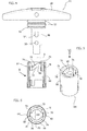
- numeral 10 indicates a switch according to the present invention, intended to be used, in particular, as a battery cutout switch for vehicles, boats, etc.
- the switch 10 comprises a housing 12 of plastic material, including a base 14 and a cover 16.
- the cover 16 is attached to the base 14, for example by means of screws 18. Between the cover 16 and the base 14, a gasket 20 may be placed.
- the switch 10 comprises two pairs of fixed electrical contacts 22.
- Each fixed contact 22 has the shape of a pin with an enlarged head and a threaded shank.
- the shanks of the fixed contacts 22 extend through respective holes of the base 14 and are attached to the base 14 by means of respective nuts 24.
- respective O-rings 26 can be provided on the shanks of the fixed contacts 22.
- a contact-holder body 28 is mounted within the housing 12.
- the contact-holder body 28 is movable relative to the housing 12 along a longitudinal axis A.
- a rectilinear guide is provided, for guiding the contact-holder body 28 along the rectilinear direction of the axis A.
- the guide can be formed by ribs projecting from the inner walls of the base 14 and between which the side edges of the contact-holder body 28 are engaged, in a drawer-like manner.
- the contact-holder body 28 carries at least one movable electrical contact.
- the contact-holder body 28 has two through-openings 30 in which two movable electrical contacts 32 are housed, each of which cooperates with a pair of fixed contacts 22.
- Each movable electrical contact 32 has the shape of an elongated metal plate, with a central portion and two side portions that protrude from opposite sides of the contact-holder body 28.
- the movable contacts 32 are retained by the contact-holder body 28 by means of respective springs 34, 36.
- the springs 34 are arranged coaxially within the springs 36 to increase the stiffness of the elastic connection between the movable contacts 32 and the contact-holder body 28.
- the springs 34, 36 act between the central portion of the respective movable contact 32 and an upper wall of the opening 30, and elastically press the movable electrical contacts 32 against the lower wall of the respective opening 30.
- the side portions of the movable electrical contacts 32 that protrude from opposite sides of the contact-holder body 28 are facing the heads of a respective pair of fixed contacts 22.
- the contact-holder body 28 is movable along the longitudinal direction A between a closed contacts position, in which the two movable contacts 32 are pressed against the heads of the fixed electrical contacts 22, and an open contacts position, in which the movable contacts 32 are detached from the fixed contacts 22.
- Elastic means are provided to push the contact-holder body 28 towards the open contacts position.
- these elastic means are formed by a pair of compression coil springs 38 acting between the bottom wall of the base 14 and a pair of side protrusions 40 of the contact-holder body 28.
- the cover 16 of the housing 12 has an integral tubular neck 42, coaxial to the longitudinal axis A.
- a control handle 44 is inserted within the tubular neck 42, and is rotatable about the longitudinal axis A between an open position and a closed position.
- the handle 44 has a shaft 46 inserted within the tubular neck 42, and a handgrip 48 projecting from the upper edge of the tubular neck 42.
- the handle 44 has a collar 50 provided on the shaft 46 at the base of the handgrip 48. On the collar 50, a pair of O-rings 52 is provided, which form a seal on the inner surface of the tubular neck 42.
- the shaft 46 of the handle 44 has at least one first control member 54 and at least one second control member 56.
- the control members 54, 56 are formed by pin-shaped elements projecting in a radial direction from the side wall of the shaft 46. In the illustrated example, two first control members 54 and two second control members 56 are provided. Each control member 54, 56 is offset by 180° with respect to the counterpart control member. The second control members 56 are spaced apart in the direction of the longitudinal axis A with respect to the first control members 54.
- the tubular neck 42 of the cover 16 has a shoulder 58 projecting radially inwards from the side wall of the neck 42.
- the collar 50 of the handle 44 rests on the upper surface of the shoulder 58.
- the shoulder 58 has a hole 60 through which the shaft 46 extends with clearance.
- the hole 60 has two openings 62 through which the engagement members 54, 56 can pass, during the insertion of the handle 44 into the neck 42 in the direction of the longitudinal axis A.
- the handle 44 is inserted in an angular position in which the engagement members 54, 56 are aligned with the openings 62 of the shoulder 58.
- the insertion position of the handle 44 is angularly offset with respect to the work positions.
- the handle 44 is free to rotate about the longitudinal axis A with respect to the housing 12, but is constrained within the housing 12 in the direction of the longitudinal axis A.
- the switch 10 comprises a cam 64 fixed with respect to the contact-holder body 28.
- the cam 64 is a separate component that is snap-fixed to an appendage 65 of the contact-holder body 28.
- the cam 64 can be integrally formed within the contact-holder body 28.
- the cam 64 comprises an outer tubular wall 66, within which the shaft portion 46 of the handle 44 carrying the control members 54, 56, extends.
- the cam 64 has at least one inclined ramp 68 projecting radially inwards from the side wall 66.
- the cam 64 has two inclined ramps 68. Each ramp 68 has two active surfaces 70, 72 opposite to each other.
- the first stop member 54 is located above the first active surface 70, and the second stop member 56 is located below the second active surface 72.
- each inclined ramp 68 has two notches 74, 76 on its first active surface 70, in which the first control member 54 engages, in the open position and the closed position of the handle 44, respectively.
- the cam 64 is provided with two stops 78 formed by ribs projecting radially inwards from the outer tubular wall 66.
- the stops 78 are arranged in positions that are angularly offset from each other by 180°.
- Each stop 78 is placed at the upper end of the corresponding inclined ramp 68.
- the control members 54, 56 come into abutment against the stops 78 in the insertion/extraction position of the handle 44 and in the closed position of the handle 44.
- two free spaces 80 are formed, through which the second control members 56 can pass during insertion and extraction of the handle 44.
- control members 54, 56 are respectively arranged above the first active surface 70, and below the second active surface 72 of the respective inclined ramp 68.
- the first control members 54 engage the respective notches 74 located at the lower ends of the respective inclined ramps 68.
- the first control members 54 slide on the first active surfaces 70 and push down the contact-holder body 28, compressing the springs 38, which tend to push the contact-holder body 28 upwards.
- the first control members 54 engage the notches 76 located at the upper ends of the active surfaces 70.
- the notches 76 stably hold the handle 44 in the closed position.
- the movable electrical contacts 32 are pressed in contact with the fixed electrical contacts 22.
- the force of the springs 38 may not be able to push the contact-holder body 28 towards the open contacts position.
- the rotation of the handle 44 from the closed position towards the open position drags the cam 64 and the contact-holder body 28 upwards, thanks to the contact between the second control members 56 with the second active surfaces 72 of the inclined ramps 68.
- the handle 44 exerts a positive action on the cam 64, both in the closing of the contacts step and during the opening of the contacts step.
- the upward dragging of the cam 64 of the contact-holder body 28 by the second control members 56 constitutes a safety feature as it ensures the opening of the contacts even in the event of abnormalities, such as the adhesion of the movable contacts 32 to the fixed contacts 22, or the failure of the springs 38.
Landscapes
- Switch Cases, Indication, And Locking (AREA)
- Keying Circuit Devices (AREA)
- Battery Mounting, Suspending (AREA)
- Charge And Discharge Circuits For Batteries Or The Like (AREA)
- Rotary Switch, Piano Key Switch, And Lever Switch (AREA)
Claims (4)
- Schalter, insbesondere ein Batterietrennschalter für Fahrzeuge, umfassend:- ein Gehäuse(12), das mindestens ein Paar feste elektrische Kontakte (22) trägt,- einen Kontakthalterkörper (28), der mindestens einen verschiebbaren elektrischen Kontakt (32) trägt, wobei der Kontakthalterkörper (28) entlang einer Längsachse (A) zwischen einer offenen Kontaktposition und einer geschlossenen Kontaktposition verschiebbar ist,- elastische Mittel (38), die zwischen dem Gehäuse (12) und dem Kontakthalterkörper (28) angeordnet sind und dazu neigen, den Kontakthalterkörper (28) in Richtung der offenen Kontaktposition zu schieben,- einen Griff (44), der um die Längsachse (A) zwischen einer offenen Position und einer geschlossenen Position drehbar ist,- einen Nocken (64), der in Bezug auf den Kontakthalterkörper (28) befestigt ist,wobei der Griff (44) mit dem Nocken (64) kooperiert, um bei Drehung des Griffs von der offenen Position in die geschlossene Position den Kontakthalterkörper (28) von der offenen Kontaktposition in die geschlossene Kontaktposition zu verschieben,
dadurch gekennzeichnet, dass der Nocken (64) mindestens eine erste und mindestens eine zweite aktive Fläche (70, 72) aufweist und der Griff (44) mindestens ein erstes Steuerglied (54) aufweist, das mit der ersten aktiven Fläche (70) kooperiert, und mindestens ein zweites Steuerglied (56) aufweist, das mit der zweiten aktiven Fläche (72) kooperiert, wobei die erste und zweite aktive Fläche (70, 72) und das erste und zweite Steuerglied (54, 56) so angeordnet sind, dass bei Drehung des Griffs (44) von der offenen Position in die geschlossene Position das erste Steuerglied (54) mit der ersten aktiven Fläche(70) kooperiert, um den Kontakthalterkörper (28) von der offenen Kontaktposition in die geschlossene Kontaktposition zu verschieben, und bei Drehung des Griffs (44) von der geschlossenen Position in die offene Position das zweite Steuerglied (56) mit der zweiten aktiven Fläche (72) kooperiert, um den Kontakthalterkörper (28) von der geschlossenen Kontaktposition in die offene Kontaktposition zu verschieben. - Schalter nach Anspruch 1, dadurch gekennzeichnet, dass der Nocken (64) eine röhrenförmige Außenwand (66) mit mindestens einer geneigten Rampe (68) umfasst, die von deren Innenfläche radial nach innen ragt, wobei die aktiven Flächen (70, 72) auf den gegenüberliegenden Seiten der geneigten Rampe (68) ausgebildet sind.
- Schalter nach Anspruch 1 oder Anspruch 2, dadurch gekennzeichnet, dass die Steuerglieder (54, 56) durch Stifte gebildet sind, die radial nach außen ragen und in Richtung der Längsachse (A) voneinander beabstandet sind.
- Schalter nach Anspruch 1 oder Anspruch 2, dadurch gekennzeichnet, dass die erste aktive Fläche (70) mit zwei Kerben (74, 76) versehen ist, in die das erste Steuerglied (54) in der offenen und geschlossenen Position des Griffs (44) eingreift.
Applications Claiming Priority (1)
| Application Number | Priority Date | Filing Date | Title |
|---|---|---|---|
| IT000457A ITTO20130457A1 (it) | 2013-06-04 | 2013-06-04 | Interruttore, in particolare interruttore staccabatterie per veicoli e simili |
Publications (2)
| Publication Number | Publication Date |
|---|---|
| EP2811500A1 EP2811500A1 (de) | 2014-12-10 |
| EP2811500B1 true EP2811500B1 (de) | 2016-02-24 |
Family
ID=48748464
Family Applications (1)
| Application Number | Title | Priority Date | Filing Date |
|---|---|---|---|
| EP14160649.1A Active EP2811500B1 (de) | 2013-06-04 | 2014-03-19 | Ein Schalter, insbesondere einem Batterietrennschalter für Fahrzeuge |
Country Status (3)
| Country | Link |
|---|---|
| EP (1) | EP2811500B1 (de) |
| ES (1) | ES2566611T3 (de) |
| IT (1) | ITTO20130457A1 (de) |
Families Citing this family (4)
| Publication number | Priority date | Publication date | Assignee | Title |
|---|---|---|---|---|
| DE102014226618A1 (de) * | 2014-12-19 | 2016-06-23 | Siemens Aktiengesellschaft | Drehbetätiger |
| GB2589107A (en) * | 2019-09-05 | 2021-05-26 | Eaton Intelligent Power Ltd | Semi-independent switch-disconnector |
| CN114326918B (zh) * | 2021-12-24 | 2023-06-27 | 广东电网有限责任公司 | 一种远程操控装置 |
| CN118039381A (zh) * | 2022-11-04 | 2024-05-14 | 施耐德电气工业公司 | 动触头驱动装置和开关设备 |
Family Cites Families (2)
| Publication number | Priority date | Publication date | Assignee | Title |
|---|---|---|---|---|
| ATE56306T1 (de) * | 1985-10-24 | 1990-09-15 | Square D Deutschland | Schaltgeraet. |
| PT1296343E (pt) * | 2001-09-21 | 2004-04-30 | Menber S Spa | Interruptor em particular interruptor para desligar a bateria para veiculos e similares |
-
2013
- 2013-06-04 IT IT000457A patent/ITTO20130457A1/it unknown
-
2014
- 2014-03-19 ES ES14160649.1T patent/ES2566611T3/es active Active
- 2014-03-19 EP EP14160649.1A patent/EP2811500B1/de active Active
Also Published As
| Publication number | Publication date |
|---|---|
| EP2811500A1 (de) | 2014-12-10 |
| ITTO20130457A1 (it) | 2014-12-05 |
| ES2566611T3 (es) | 2016-04-14 |
Similar Documents
| Publication | Publication Date | Title |
|---|---|---|
| US9653235B2 (en) | Switch device | |
| EP2811500B1 (de) | Ein Schalter, insbesondere einem Batterietrennschalter für Fahrzeuge | |
| US6821126B2 (en) | Electromechanical connecting device | |
| JP5644657B2 (ja) | 車載用電気機器のシールカバー | |
| EP2767997B1 (de) | Hebeldichtungsstruktur und elektrisches Werkzeug damit | |
| EP3107110B1 (de) | Kontaktmechanismus, auslöseschalter umfassend den kontaktmechanismus und elektrisches werkzeug | |
| US9478911B2 (en) | Locking mechanism for plug-in connectors | |
| US8952278B2 (en) | Interlocking mechanism for switching devices | |
| EP3273462A1 (de) | Kippschalterbetätigungsmechanismus | |
| US20170352505A1 (en) | Switch of battery | |
| KR200479581Y1 (ko) | 커넥터 어셈블리 | |
| EP2811498B1 (de) | Ein Schalter, insbesondere ein Batterietrennschalter für Fahrzeuge | |
| KR101508501B1 (ko) | 커넥터 어셈블리 | |
| US20170018380A1 (en) | Switch device | |
| EP2811499B1 (de) | Ein Schalter, insbesondere ein Batterietrennschalter für Fahrzeuge | |
| KR102329759B1 (ko) | 토글 스위치 장치 | |
| KR101585861B1 (ko) | 커넥터 어셈블리 | |
| EP2811501B1 (de) | Ein Schalter, insbesondere ein Batterietrennschalter für Fahrzeuge | |
| JP6132205B2 (ja) | コネクタ | |
| JP6244227B2 (ja) | 電源回路遮断装置 | |
| KR20160070020A (ko) | 전기 푸시버튼 스냅 스위치 | |
| CN105321753B (zh) | 用于制造紧凑式按键部件的方法 | |
| US10049844B2 (en) | Electrical disconnect device for a battery | |
| KR101752338B1 (ko) | 푸시-록 스위치 | |
| EP3078047B1 (de) | Mastertrennschalter mit kontaktverschweissungsschutzschalter |
Legal Events
| Date | Code | Title | Description |
|---|---|---|---|
| PUAI | Public reference made under article 153(3) epc to a published international application that has entered the european phase |
Free format text: ORIGINAL CODE: 0009012 |
|
| 17P | Request for examination filed |
Effective date: 20140319 |
|
| AK | Designated contracting states |
Kind code of ref document: A1 Designated state(s): AL AT BE BG CH CY CZ DE DK EE ES FI FR GB GR HR HU IE IS IT LI LT LU LV MC MK MT NL NO PL PT RO RS SE SI SK SM TR |
|
| AX | Request for extension of the european patent |
Extension state: BA ME |
|
| R17P | Request for examination filed (corrected) |
Effective date: 20150511 |
|
| RBV | Designated contracting states (corrected) |
Designated state(s): AL AT BE BG CH CY CZ DE DK EE ES FI FR GB GR HR HU IE IS IT LI LT LU LV MC MK MT NL NO PL PT RO RS SE SI SK SM TR |
|
| RIC1 | Information provided on ipc code assigned before grant |
Ipc: H01H 3/42 20060101ALN20150703BHEP Ipc: H01H 1/50 20060101ALN20150703BHEP Ipc: H01H 1/20 20060101ALN20150703BHEP Ipc: H01H 19/62 20060101ALI20150703BHEP Ipc: H01H 3/02 20060101AFI20150703BHEP Ipc: H01H 19/14 20060101ALN20150703BHEP Ipc: H01H 25/06 20060101ALN20150703BHEP Ipc: H01H 3/20 20060101ALN20150703BHEP Ipc: H01H 9/28 20060101ALN20150703BHEP |
|
| GRAP | Despatch of communication of intention to grant a patent |
Free format text: ORIGINAL CODE: EPIDOSNIGR1 |
|
| INTG | Intention to grant announced |
Effective date: 20150819 |
|
| GRAS | Grant fee paid |
Free format text: ORIGINAL CODE: EPIDOSNIGR3 |
|
| GRAA | (expected) grant |
Free format text: ORIGINAL CODE: 0009210 |
|
| AK | Designated contracting states |
Kind code of ref document: B1 Designated state(s): AL AT BE BG CH CY CZ DE DK EE ES FI FR GB GR HR HU IE IS IT LI LT LU LV MC MK MT NL NO PL PT RO RS SE SI SK SM TR |
|
| REG | Reference to a national code |
Ref country code: GB Ref legal event code: FG4D Ref country code: FR Ref legal event code: PLFP Year of fee payment: 3 |
|
| REG | Reference to a national code |
Ref country code: CH Ref legal event code: EP |
|
| REG | Reference to a national code |
Ref country code: AT Ref legal event code: REF Ref document number: 777106 Country of ref document: AT Kind code of ref document: T Effective date: 20160315 |
|
| REG | Reference to a national code |
Ref country code: IE Ref legal event code: FG4D |
|
| REG | Reference to a national code |
Ref country code: DE Ref legal event code: R096 Ref document number: 602014000938 Country of ref document: DE |
|
| REG | Reference to a national code |
Ref country code: ES Ref legal event code: FG2A Ref document number: 2566611 Country of ref document: ES Kind code of ref document: T3 Effective date: 20160414 |
|
| REG | Reference to a national code |
Ref country code: LT Ref legal event code: MG4D |
|
| REG | Reference to a national code |
Ref country code: NL Ref legal event code: MP Effective date: 20160224 |
|
| REG | Reference to a national code |
Ref country code: AT Ref legal event code: MK05 Ref document number: 777106 Country of ref document: AT Kind code of ref document: T Effective date: 20160224 |
|
| PG25 | Lapsed in a contracting state [announced via postgrant information from national office to epo] |
Ref country code: HR Free format text: LAPSE BECAUSE OF FAILURE TO SUBMIT A TRANSLATION OF THE DESCRIPTION OR TO PAY THE FEE WITHIN THE PRESCRIBED TIME-LIMIT Effective date: 20160224 Ref country code: FI Free format text: LAPSE BECAUSE OF FAILURE TO SUBMIT A TRANSLATION OF THE DESCRIPTION OR TO PAY THE FEE WITHIN THE PRESCRIBED TIME-LIMIT Effective date: 20160224 Ref country code: GR Free format text: LAPSE BECAUSE OF FAILURE TO SUBMIT A TRANSLATION OF THE DESCRIPTION OR TO PAY THE FEE WITHIN THE PRESCRIBED TIME-LIMIT Effective date: 20160525 Ref country code: NO Free format text: LAPSE BECAUSE OF FAILURE TO SUBMIT A TRANSLATION OF THE DESCRIPTION OR TO PAY THE FEE WITHIN THE PRESCRIBED TIME-LIMIT Effective date: 20160524 Ref country code: IT Free format text: LAPSE BECAUSE OF FAILURE TO SUBMIT A TRANSLATION OF THE DESCRIPTION OR TO PAY THE FEE WITHIN THE PRESCRIBED TIME-LIMIT Effective date: 20160224 |
|
| PG25 | Lapsed in a contracting state [announced via postgrant information from national office to epo] |
Ref country code: AT Free format text: LAPSE BECAUSE OF FAILURE TO SUBMIT A TRANSLATION OF THE DESCRIPTION OR TO PAY THE FEE WITHIN THE PRESCRIBED TIME-LIMIT Effective date: 20160224 Ref country code: PT Free format text: LAPSE BECAUSE OF FAILURE TO SUBMIT A TRANSLATION OF THE DESCRIPTION OR TO PAY THE FEE WITHIN THE PRESCRIBED TIME-LIMIT Effective date: 20160624 Ref country code: BE Free format text: LAPSE BECAUSE OF NON-PAYMENT OF DUE FEES Effective date: 20160331 Ref country code: NL Free format text: LAPSE BECAUSE OF FAILURE TO SUBMIT A TRANSLATION OF THE DESCRIPTION OR TO PAY THE FEE WITHIN THE PRESCRIBED TIME-LIMIT Effective date: 20160224 Ref country code: PL Free format text: LAPSE BECAUSE OF FAILURE TO SUBMIT A TRANSLATION OF THE DESCRIPTION OR TO PAY THE FEE WITHIN THE PRESCRIBED TIME-LIMIT Effective date: 20160224 Ref country code: LV Free format text: LAPSE BECAUSE OF FAILURE TO SUBMIT A TRANSLATION OF THE DESCRIPTION OR TO PAY THE FEE WITHIN THE PRESCRIBED TIME-LIMIT Effective date: 20160224 Ref country code: LT Free format text: LAPSE BECAUSE OF FAILURE TO SUBMIT A TRANSLATION OF THE DESCRIPTION OR TO PAY THE FEE WITHIN THE PRESCRIBED TIME-LIMIT Effective date: 20160224 Ref country code: SE Free format text: LAPSE BECAUSE OF FAILURE TO SUBMIT A TRANSLATION OF THE DESCRIPTION OR TO PAY THE FEE WITHIN THE PRESCRIBED TIME-LIMIT Effective date: 20160224 Ref country code: RS Free format text: LAPSE BECAUSE OF FAILURE TO SUBMIT A TRANSLATION OF THE DESCRIPTION OR TO PAY THE FEE WITHIN THE PRESCRIBED TIME-LIMIT Effective date: 20160224 |
|
| PG25 | Lapsed in a contracting state [announced via postgrant information from national office to epo] |
Ref country code: DK Free format text: LAPSE BECAUSE OF FAILURE TO SUBMIT A TRANSLATION OF THE DESCRIPTION OR TO PAY THE FEE WITHIN THE PRESCRIBED TIME-LIMIT Effective date: 20160224 Ref country code: EE Free format text: LAPSE BECAUSE OF FAILURE TO SUBMIT A TRANSLATION OF THE DESCRIPTION OR TO PAY THE FEE WITHIN THE PRESCRIBED TIME-LIMIT Effective date: 20160224 |
|
| REG | Reference to a national code |
Ref country code: DE Ref legal event code: R097 Ref document number: 602014000938 Country of ref document: DE |
|
| PG25 | Lapsed in a contracting state [announced via postgrant information from national office to epo] |
Ref country code: CZ Free format text: LAPSE BECAUSE OF FAILURE TO SUBMIT A TRANSLATION OF THE DESCRIPTION OR TO PAY THE FEE WITHIN THE PRESCRIBED TIME-LIMIT Effective date: 20160224 Ref country code: RO Free format text: LAPSE BECAUSE OF FAILURE TO SUBMIT A TRANSLATION OF THE DESCRIPTION OR TO PAY THE FEE WITHIN THE PRESCRIBED TIME-LIMIT Effective date: 20160224 Ref country code: SM Free format text: LAPSE BECAUSE OF FAILURE TO SUBMIT A TRANSLATION OF THE DESCRIPTION OR TO PAY THE FEE WITHIN THE PRESCRIBED TIME-LIMIT Effective date: 20160224 Ref country code: SK Free format text: LAPSE BECAUSE OF FAILURE TO SUBMIT A TRANSLATION OF THE DESCRIPTION OR TO PAY THE FEE WITHIN THE PRESCRIBED TIME-LIMIT Effective date: 20160224 |
|
| REG | Reference to a national code |
Ref country code: IE Ref legal event code: MM4A |
|
| PG25 | Lapsed in a contracting state [announced via postgrant information from national office to epo] |
Ref country code: BE Free format text: LAPSE BECAUSE OF FAILURE TO SUBMIT A TRANSLATION OF THE DESCRIPTION OR TO PAY THE FEE WITHIN THE PRESCRIBED TIME-LIMIT Effective date: 20160224 |
|
| PLBE | No opposition filed within time limit |
Free format text: ORIGINAL CODE: 0009261 |
|
| STAA | Information on the status of an ep patent application or granted ep patent |
Free format text: STATUS: NO OPPOSITION FILED WITHIN TIME LIMIT |
|
| PG25 | Lapsed in a contracting state [announced via postgrant information from national office to epo] |
Ref country code: IE Free format text: LAPSE BECAUSE OF NON-PAYMENT OF DUE FEES Effective date: 20160319 |
|
| 26N | No opposition filed |
Effective date: 20161125 |
|
| PG25 | Lapsed in a contracting state [announced via postgrant information from national office to epo] |
Ref country code: SI Free format text: LAPSE BECAUSE OF FAILURE TO SUBMIT A TRANSLATION OF THE DESCRIPTION OR TO PAY THE FEE WITHIN THE PRESCRIBED TIME-LIMIT Effective date: 20160224 Ref country code: BG Free format text: LAPSE BECAUSE OF FAILURE TO SUBMIT A TRANSLATION OF THE DESCRIPTION OR TO PAY THE FEE WITHIN THE PRESCRIBED TIME-LIMIT Effective date: 20160524 |
|
| REG | Reference to a national code |
Ref country code: FR Ref legal event code: PLFP Year of fee payment: 4 |
|
| PG25 | Lapsed in a contracting state [announced via postgrant information from national office to epo] |
Ref country code: MT Free format text: LAPSE BECAUSE OF FAILURE TO SUBMIT A TRANSLATION OF THE DESCRIPTION OR TO PAY THE FEE WITHIN THE PRESCRIBED TIME-LIMIT Effective date: 20160224 |
|
| REG | Reference to a national code |
Ref country code: CH Ref legal event code: PL |
|
| PG25 | Lapsed in a contracting state [announced via postgrant information from national office to epo] |
Ref country code: LI Free format text: LAPSE BECAUSE OF NON-PAYMENT OF DUE FEES Effective date: 20170331 Ref country code: CH Free format text: LAPSE BECAUSE OF NON-PAYMENT OF DUE FEES Effective date: 20170331 |
|
| REG | Reference to a national code |
Ref country code: FR Ref legal event code: PLFP Year of fee payment: 5 |
|
| REG | Reference to a national code |
Ref country code: ES Ref legal event code: PC2A Owner name: LITTLEFUSE COMMERCIAL VEHICLE PRODUCTS, ITALY S.R. Effective date: 20180416 |
|
| REG | Reference to a national code |
Ref country code: DE Ref legal event code: R082 Ref document number: 602014000938 Country of ref document: DE Representative=s name: GULDE & PARTNER PATENT- UND RECHTSANWALTSKANZL, DE Ref country code: DE Ref legal event code: R081 Ref document number: 602014000938 Country of ref document: DE Owner name: LITTELFUSE COMMERCIAL VEHICLE PRODUCTS, ITALY , IT Free format text: FORMER OWNER: MENBER'S S.P.A., LEGNAGO, VERONA, IT |
|
| PG25 | Lapsed in a contracting state [announced via postgrant information from national office to epo] |
Ref country code: HU Free format text: LAPSE BECAUSE OF FAILURE TO SUBMIT A TRANSLATION OF THE DESCRIPTION OR TO PAY THE FEE WITHIN THE PRESCRIBED TIME-LIMIT; INVALID AB INITIO Effective date: 20140319 |
|
| PG25 | Lapsed in a contracting state [announced via postgrant information from national office to epo] |
Ref country code: LU Free format text: LAPSE BECAUSE OF NON-PAYMENT OF DUE FEES Effective date: 20160319 Ref country code: IS Free format text: LAPSE BECAUSE OF FAILURE TO SUBMIT A TRANSLATION OF THE DESCRIPTION OR TO PAY THE FEE WITHIN THE PRESCRIBED TIME-LIMIT Effective date: 20160224 Ref country code: MC Free format text: LAPSE BECAUSE OF FAILURE TO SUBMIT A TRANSLATION OF THE DESCRIPTION OR TO PAY THE FEE WITHIN THE PRESCRIBED TIME-LIMIT Effective date: 20160224 Ref country code: MT Free format text: LAPSE BECAUSE OF FAILURE TO SUBMIT A TRANSLATION OF THE DESCRIPTION OR TO PAY THE FEE WITHIN THE PRESCRIBED TIME-LIMIT Effective date: 20160331 Ref country code: MK Free format text: LAPSE BECAUSE OF FAILURE TO SUBMIT A TRANSLATION OF THE DESCRIPTION OR TO PAY THE FEE WITHIN THE PRESCRIBED TIME-LIMIT Effective date: 20160224 Ref country code: CY Free format text: LAPSE BECAUSE OF FAILURE TO SUBMIT A TRANSLATION OF THE DESCRIPTION OR TO PAY THE FEE WITHIN THE PRESCRIBED TIME-LIMIT Effective date: 20160224 |
|
| REG | Reference to a national code |
Ref country code: FR Ref legal event code: CA Effective date: 20180724 Ref country code: FR Ref legal event code: CD Owner name: LITTELFUSE COMMERCIAL VEHICLE PRODUCTS, ITALY , IT Effective date: 20180724 Ref country code: FR Ref legal event code: CJ Effective date: 20180724 Ref country code: FR Ref legal event code: TP Owner name: LITTELFUSE COMMERCIAL VEHICLE PRODUCTS, ITALY , IT Effective date: 20180724 |
|
| PG25 | Lapsed in a contracting state [announced via postgrant information from national office to epo] |
Ref country code: AL Free format text: LAPSE BECAUSE OF FAILURE TO SUBMIT A TRANSLATION OF THE DESCRIPTION OR TO PAY THE FEE WITHIN THE PRESCRIBED TIME-LIMIT Effective date: 20160224 Ref country code: TR Free format text: LAPSE BECAUSE OF FAILURE TO SUBMIT A TRANSLATION OF THE DESCRIPTION OR TO PAY THE FEE WITHIN THE PRESCRIBED TIME-LIMIT Effective date: 20160224 |
|
| GBPC | Gb: european patent ceased through non-payment of renewal fee |
Effective date: 20180319 |
|
| PG25 | Lapsed in a contracting state [announced via postgrant information from national office to epo] |
Ref country code: GB Free format text: LAPSE BECAUSE OF NON-PAYMENT OF DUE FEES Effective date: 20180319 |
|
| P01 | Opt-out of the competence of the unified patent court (upc) registered |
Effective date: 20230607 |
|
| PGFP | Annual fee paid to national office [announced via postgrant information from national office to epo] |
Ref country code: ES Payment date: 20250408 Year of fee payment: 12 |
|
| PGFP | Annual fee paid to national office [announced via postgrant information from national office to epo] |
Ref country code: FR Payment date: 20251231 Year of fee payment: 13 |
|
| PGFP | Annual fee paid to national office [announced via postgrant information from national office to epo] |
Ref country code: DE Payment date: 20260102 Year of fee payment: 13 |