EP3078047B1 - Mastertrennschalter mit kontaktverschweissungsschutzschalter - Google Patents
Mastertrennschalter mit kontaktverschweissungsschutzschalter Download PDFInfo
- Publication number
- EP3078047B1 EP3078047B1 EP14868454.1A EP14868454A EP3078047B1 EP 3078047 B1 EP3078047 B1 EP 3078047B1 EP 14868454 A EP14868454 A EP 14868454A EP 3078047 B1 EP3078047 B1 EP 3078047B1
- Authority
- EP
- European Patent Office
- Prior art keywords
- shaft
- contact
- central axis
- switch
- contact plate
- Prior art date
- Legal status (The legal status is an assumption and is not a legal conclusion. Google has not performed a legal analysis and makes no representation as to the accuracy of the status listed.)
- Active
Links
- -1 for example Substances 0.000 description 5
- 238000010586 diagram Methods 0.000 description 4
- 239000000919 ceramic Substances 0.000 description 3
- 239000012811 non-conductive material Substances 0.000 description 3
- 238000005192 partition Methods 0.000 description 3
- RYGMFSIKBFXOCR-UHFFFAOYSA-N Copper Chemical compound [Cu] RYGMFSIKBFXOCR-UHFFFAOYSA-N 0.000 description 2
- 239000004593 Epoxy Substances 0.000 description 2
- XEEYBQQBJWHFJM-UHFFFAOYSA-N Iron Chemical compound [Fe] XEEYBQQBJWHFJM-UHFFFAOYSA-N 0.000 description 2
- 239000004020 conductor Substances 0.000 description 2
- 239000010949 copper Substances 0.000 description 2
- 229910052802 copper Inorganic materials 0.000 description 2
- 239000000463 material Substances 0.000 description 2
- 229910001369 Brass Inorganic materials 0.000 description 1
- 230000004075 alteration Effects 0.000 description 1
- 239000010951 brass Substances 0.000 description 1
- 230000001419 dependent effect Effects 0.000 description 1
- 238000010438 heat treatment Methods 0.000 description 1
- 229910052742 iron Inorganic materials 0.000 description 1
- 238000012423 maintenance Methods 0.000 description 1
- 238000012986 modification Methods 0.000 description 1
- 230000004048 modification Effects 0.000 description 1
- 229910001220 stainless steel Inorganic materials 0.000 description 1
- 239000010935 stainless steel Substances 0.000 description 1
Images


Classifications
-
- H—ELECTRICITY
- H01—ELECTRIC ELEMENTS
- H01H—ELECTRIC SWITCHES; RELAYS; SELECTORS; EMERGENCY PROTECTIVE DEVICES
- H01H3/00—Mechanisms for operating contacts
- H01H3/001—Means for preventing or breaking contact-welding
-
- H—ELECTRICITY
- H01—ELECTRIC ELEMENTS
- H01H—ELECTRIC SWITCHES; RELAYS; SELECTORS; EMERGENCY PROTECTIVE DEVICES
- H01H19/00—Switches operated by an operating part which is rotatable about a longitudinal axis thereof and which is acted upon directly by a solid body external to the switch, e.g. by a hand
- H01H19/54—Switches operated by an operating part which is rotatable about a longitudinal axis thereof and which is acted upon directly by a solid body external to the switch, e.g. by a hand the operating part having at least five or an unspecified number of operative positions
- H01H19/60—Angularly-movable actuating part carrying no contacts
- H01H19/635—Contacts actuated by rectilinearly-movable member linked to operating part, e.g. by pin and slot
- H01H19/6355—Contacts actuated by rectilinearly-movable member linked to operating part, e.g. by pin and slot using axial cam devices for transforming the angular movement into linear movement along the axis of rotation
Definitions
- Embodiments of the present disclosure relate generally to switches and more particularly to master disconnect switches that may be used in vehicles.
- Switches may be used to disconnect a power supply from a load. Examples of electrical switches are disclosed in US 3 739 109 A and EP 1 553 609 A1 . Furthermore, US 4 538 036 A discloses an electrical switch which is similar to the switch as described in the introductory portion of claim 1.
- vehicles may include a switch (sometimes referred to as a master disconnect switch) that electrically disconnects the battery from the circuits in the vehicle. This may be used to ensure that power is not supplied to the vehicle prior to performing maintenance.
- the switch may be placed in the ON position to electrically connect the power source (e.g., battery) to the load (e.g., vehicle circuits). When the switch is placed in the ON position, the contacts in the switch are closed. Accordingly, current may flow from the power source to the load through the contacts.
- the user may place the switch in the OFF position, which opens the contacts and breaks the circuit.
- the contacts may be heated up due to the amount of current flowing from the power source. Heating of the contacts may cause them to fuse together. This is often referred to as a contact weld. Accordingly, when the switch is activated to open the contacts, they may not open due to the contact weld. As such, the battery will still be electrically connected to the vehicle. Some conventional switches do not provide a way for the contact weld to be broken, thus preventing the contacts from opening. Furthermore, some conventional switches do not provide feedback to let an operator know whether the contacts are actually open or closed. As such, an operator may believe that the battery is electrically disconnected when in actuality it is not.
- Exemplary embodiments of the present disclosure are directed to a switch, usable as a master disconnect switch in a vehicle, which facilitates breaking contact welds to open the switch and also provides positive feedback as to whether the contacts are open or closed.
- the switch may have first and second terminals to connect a source of power to a load, a shaft rotatable about a central axis and moveable longitudinally along the central axis, the shaft having a wing extending out orthogonally from the central axis, a contact plate to physically and electrically connect the first and second terminals when the shaft is moved longitudinally along the central axis, and a disengagement ramp to contact the wing when the shaft is rotated about the central axis, the disengagement ramp to force the shaft to move longitudinally along the central axis as the shaft is rotated to move the contact plate away from the first and second terminals.
- the switch including a first stud for connecting to a source of power, a second stud for connecting to a load, a shaft rotatable about a central axis and moveable along the length of the central axis, the shaft having a first wing and a second wing, the first and second wing extending out orthogonally from the central axis, a contact plate disposed on the shaft, the contact plate to electrically connect the first and second studs when the shaft is moved longitudinally along the central axis to electrically connect a source of power to a load, and a first disengagement ramp and a second disengagement ramp to contact the first and second wings when the shaft is rotated about the central axis to force the shaft to move longitudinally and move the contact plate away from the first and second studs to electrically disconnect the first and second studs.
- FIGS. 1A-1G illustrate block diagrams of a master disconnect switch 1000.
- FIGS. 1A-1D describe the various component parts of the switch 1000 while FIGS. 1E-1G describe the operation of the switch 1000.
- the master disconnect switch 1000 includes a terminal housing 100 and a contact housing 200, which are configured to be mated together to form the switch 1000.
- the examples herein show the terminal housing 100 fitting into a cavity in the contact housing 200, this is not intended to be limiting.
- the contact housing may fit into a cavity in the terminal housing.
- the size and shape of the examples depicted herein is done to facilitate understanding and is not intended to be limiting.
- the switch 1000 also includes a shaft disposed in the contact housing.
- the shaft has wings extending out orthogonally from a central axis and is rotatable about the central axis and moveable longitudinally along the central axis.
- the shaft may be rotated (e.g., about the central axis) to place the switch in the ON position.
- the wings contact engagement ramps. Further rotation causes the wings to slide up the engagement ramps, which causes the contacts in the switch to close and electrically connect the switch terminals.
- the shaft may be rotated (e.g., about the central axis) to place the switch in the OFF position. When the shaft is rotated, the wings travel down the engagement ramps, the contacts open and electrically disconnect the switch terminals.
- the shaft will return to a position designated or known as the OFF position to provide an indicator to an operator that the switch is indeed off.
- the wings will contact disengagement ramps. Further rotation of the shaft will cause the wings to slide down the disengagement ramps and force the contacts away from the terminals, thus breaking the contact weld and allowing the terminals to be electrically disconnected.
- the shaft will not rotate further due to the disengagement ramps, thus providing feedback to an operator that the switch is not OFF.
- FIG. 1A a top view of the terminal housing 100 is shown.
- the terminal housing may be made from any nonconductive material, such as, for example, ceramic, plastic, or the like.
- the terminal housing 100 may include a first through-hole 102 and a second through-hole 103.
- a partition 101 is disposed between the first and second through-holes 102, 103.
- the terminal housing 100 is shown having a generally circular shape, various embodiments may have other shapes (e.g., square, rectangular, or the like).
- FIG. 1C shows a cut-away side view of the terminal housing 100. As can be seen, the terminal housing 100 includes a cavity 104.
- First and second studs 110 and 120 are disposed in the first and second through-holes 102 and 103.
- the studs 110, 120 may be made from a conductive material, such as, for example, iron, copper, brass, stainless steel, or the like.
- Portions of the first and second studs 110, 120 extend out from the terminal housing 100 forming terminal portions 111 and 121.
- the terminal portions may be threaded, for example, to provide for receiving a ring terminal connection and a nut.
- the terminal portions 111, 121 of the studs 110, 120 are separated by the partition 101.
- portions of the first and second studs 110, 120 extend out from the terminal housing into the cavity 104 forming contact portions 112 and 122.
- First and second disengagement ramps 130 and 140 are disposed in the cavity 104 of the terminal housing 100.
- the disengagement ramps 130 and 140 may be positioned that when the terminal housing 100 is mated with the contact housing 200, the disengagement ramps 130, 140 may assist in breaking a contact weld between a contact plate (refer to FIG. 1D ) and the contact portions 112, 122 of the studs 110, 120 when the shaft 210 (refer to FIG. 1D ) is rotated to turn the switch OFF (refer to FIG. 1G ).
- the contact housing 200 may be made from a nonconductive material, such as, for example, ceramic, plastic, or the like. As another example, the contact housing 200 may be made from any material, provided that the contact housing 200 does not physically or electrically connect the to the contact plate 250.
- the contact housing 200 may include a third through-hole 201. Although the contact housing 200 is shown having a generally circular shape, various embodiments may have other shapes (e.g., square, rectangular, or the like).
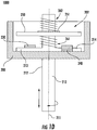
- FIG. 1D shows a cut-away side view of the contact housing 200. As can be seen, the contact housing 200 includes a cavity 202. A shaft 210 is disposed in the third through-hole 201.
- the shaft 210 may be made from a nonconductive material, such as, for example, ceramic, plastic, or the like. As another example, the shaft 210 may be made from any material, provided that shaft 210 does not physically or electrically connect the to the contact plate 250.
- the shaft 210 is rotatable about a central axis 211. Furthermore, that shaft is moveable about the length of the central axis 211.
- the shaft has an actuating portion 212 extending out from the contact housing 200.
- the actuating portion 212 may include a handle (not shown) or other means to facilitate rotating the shaft 210 about the central axis 211.
- the shaft 210 also includes wings 213 and 214 extending out orthogonally from the central axis 211.
- a contact plate 250 is disposed on the shaft 210.
- the contact plate may be made from a conductive material, such as, for example, copper, or the like.
- the contact plate 250 is fixed in place longitudinally along the central axis 211 of the shaft 210.
- the contact plate may rotate about the central axis 211. Said differently, when the shaft 210 moves along the length of the central axis 211, the contact plate will move a corresponding amount. However, when the shaft 210 rotates about the central axis 211, the contact plate may not rotate or may rotate a different amount.
- the contact plate 250 may be longitudinally fixed in place on the shaft 210 by lock ring 251. In other examples, the contact plate 250 may be longitudinally fixed in place using nuts, or other fixing means.
- the switch may include a contact spring 261 and a return spring 262.
- the contact spring 261 may be disposed between the wings 213, 214 and the contact plate 250 while the return spring 262 may be disposed between the lock ring 251 and the terminal housing 100 (e.g., refer to FIGS. 1F-1G ).
- the return spring 262 may be biased to apply pressure on the lock ring 251, and thus, the shaft 210.
- First and second engagement ramps 230 and 240 are disposed in the cavity 202 of the contact housing 200. The engagement ramps 230, 240 are positioned to contact the wings 213, 214 when the shaft 210 is rotated.
- FIG. IE the cut-away view of the contact housing 200 from FIG. 1D is shown.
- the shaft 210 is shown having been moved along the length of the central axis 211.
- the shaft 210 has moved longitudinally along the central axis 211 from the position shown in FIG. 1D .
- the shaft 210 may be moved longitudinally along the central axis 211 by rotating the shaft 210 about the central axis 211 such that the wings 213, 214 contact the engagement ramps 230, 240 and slide up the engagement ramps 230, 240, thereby moving the shaft 210.
- the wings 213, 214 have moved away from the inner surface of the contact housing 200 and are positioned near the top of the engagement ramps 230, 240.
- the switch 1000 is shown with the terminal housing 100 and the contact housing 200 mated together.
- the contact housing 200 fits inside the cavity 104 of the terminal housing 100.
- the terminal housing 100 is depicted as fitting inside the cavity 202 of the contact housing 200, this is not intended to be limiting.
- the contact housing 200 may fit inside the cavity 104 of the terminal housing 100.
- the terminal housing 100 and the contact housing 200 may be mated together by other means (e.g., epoxy, bolts, interlocking portions, or the like).
- FIG. 1F shows the switch 1000 in the ON position. More specifically, the terminals 111, 121 are shown electrically connected by the contact plate 250. That is, the contact portions 112, 122 of the studs 110, 120 are shown in physical and electrical contact with the contact plate 250, thereby electrically connecting the terminal portions 111, 121.
- power source e.g., battery, generator, or the like
- current may flow from the power source to the load.
- the switch 1000 may be turned to the ON position by rotating the shaft 210 about the central axis 211 (e.g., rotating the shaft 210 clockwise, or the like). As the shaft 210 is rotated, the wings 213, 214 contact the engagement ramps 230, 240 and slide up the engagement ramps, thus moving the contact plate 250 towards the contact portions 112, 122 of the studs 110, 120. It is important to note, that the disengagement ramps 130, 140 are not shown in FIG. 1F for clarity. Additionally, the return spring 262 may be compressed between the lock ring 251 and the terminal housing 100. More particularly, the return spring 262 may be compressed between the terminal housing 100 and the lock ring 251, which is fixed to the shaft 210.
- the return spring 262 may be compressed between the lock ring 251 and the terminal housing 100. More particularly, the return spring 262 may be compressed between the terminal housing 100 and the lock ring 251, which is fixed to the shaft 210.
- the shaft 210 As the shaft 210 continues to rotate, it moves father up the engagement ramps 230, 240 and the contact plate 250 physically contacts the contact portions 112, 122 of the studs 110, 120. Once the contact plate 250 physically contacts the studs 110, 120, the contact spring 261 compresses. When the shaft 210 is rotated so that the wings 213, 214 have moved to the top of the engagement ramps 230, 240, the wings may fall into a recess (refer to FIGS. 2A-2E ) located at the top of the ramp.
- the contact spring 261 may be biased to exert pressure on the contact plate 250 and the wings 213, 214 to assist in keeping the switch 1000 in the ON position.
- the contact spring 261 may be in a generally compressed state between the wings 213, 214 and the contact plate 250 when the wings 213, 214 are in the recesses.
- the shaft 210 may continued to rotate (e.g., to the top of the engagement ramps, or the like). As a result, the shaft 210 may continue to move longitudinally along the central axis 211, thus creating a gap (not shown) between the lock ring 251 and the contact plate 250. Additionally, the contact spring 261 may be further compressed between the contact plate 250 and the wings 213, 214, which may further assist in retaining the wings in the recesses 231, 232.
- the switch 1000 may be turned to the OFF position by rotating the shaft 210 about the central axis 211 (e.g., rotating the shaft 210 counter-clockwise, or the like).
- the wings 213, 214 will move out of the recesses at the top of the engagement ramps 230, 240 (refer to FIGS. 2A-2E ) and slide down the engagement ramps.
- the return spring 262 may assist in moving the contact plate 250 away from the contact portions 112, 122 of the studs 110, 120 by exerting pressure on the shaft 210.
- the return spring 262 will exert force on the shaft 210.
- the return spring 262 will exert force on the shaft 210 (e.g., through the lock ring 251) and assist in moving the shaft 210 longitudinally such that the switch is turned OFF.
- the return spring 262 will push the contact plate 250 away from the contact portions 112, 122 of the studs 110, 120 to electrically disconnect the terminals 111, 121 from each other.
- the shaft 210 will stop turning. Additionally, the shaft will have rotated a distance axially and/or moved a distance laterally to indicate that the switch is in the OFF position.
- the switch may be turned off even where the contact plate 250 is "stuck" to the contact portions 112, 122 of the studs 110, 120.
- the contact plate 250 may not move away from the studs due to the force of the return spring 262 alone. That is, the force on the shaft 210 from the return spring 262 may not be enough to break the contact weld between the contact plate 250 and the contact portions 112, 122 of the studs 110, 120.
- the wings 213, 214 will not slide down the engagement ramps 230, 240 (not shown for clarity) but instead will rotate around to contact the disengagement ramps 130, 140. As the wings 213, 214 contact the disengagement ramps 130, 140 they will slide down the disengagement ramps 130, 140 and force the contact plate 250 away from the studs 110, 120. As the contact plate 250 is longitudinally fixed in place on the shaft 210, the motion of the shaft 210 away from the studs 110, 120 combined with the force of the return spring 262 may be enough to break a contact weld between the contact plate 250 and the contact portions 112, 122 of the studs 110, 120.
- the shaft 210 may continue to rotate and the return spring 262 will exert force on the shaft 210 as described above to assist in moving the shaft 210 longitudinally such that the switch 1000 is turned off. Said differently, the return spring 262 will push the lock ring 251 and thus the shaft 210 and the contact plate 250 away from the contact portions 112, 122 of the studs 110, 120 to electrically disconnect the terminals 111, 121 from each other.
- the shaft 210 will stop turning. Additionally, the shaft will have rotated a distance and/or moved a distance to indicate that the switch is in the OFF position.
- the shaft 210 will not rotate about the central axis 211 past the disengagement ramps. As such, feedback may be provided to an operator that the switch is not in the OFF position. Said differently, the lack of axial rotation and/or longitudinal movement of the shaft 210 may indicate that the switch is not OFF.
- FIGS. 2A-2E illustrate isometric views of the master disconnect switch 1000.
- FIGS. 2A-2B show isometric views of the various component parts of the switch 1000 while FIGS. 2C-2E show isometric views of the switch 1000 during operation.
- FIG. 2A an isometric view of the terminal housing 100 including the cavity 104 is depicted.
- the first and second studs 110, 120 are shown disposed in the first and second through-holes 102, 103 (not shown).
- the contact portions 112, 122 and the terminal portion 111 are also shown. It is to be appreciated, that the terminal portion 121 is obscured by the angle of viewing. However, the partition 101, which separates the terminal portion 111 from the terminal portion 121 is shown.
- the first and second disengagement ramps 130, 140 are also shown. As can be seen, the disengagement ramps 130, 140 are positioned on a shelf 150 so that the disengagement ramps will contact the wings during operation (see FIGS. 2C-2E ).
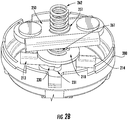
- FIG. 2B an isometric view of the contact housing 200 is shown.
- the shaft 210 disposed in the third through-hole 201 is shown. Additionally, the wings 213, 214, which extend out orthogonally from the shaft 210 are shown.
- the contact plate 250 is disposed on the shaft 210. The contact plate is fixed in place by the lock ring 251 as described above. Additionally, the contact spring 261 and the return spring 262 are shown. Engagement ramp 230, including recess 231 is also shown. It is to be appreciated, that the engagement ramp 240 and corresponding recess 241 are obscured by the viewing angle.
- the switch 1000 is shown.
- the shaft 210 is shown being rotated from the OFF position to the ON position.
- the switch 1000 may be turned to the ON position by rotating the shaft 210 about the central axis.
- the wings 213, 214 contact the engagement ramps 230, 240 and slide up the engagement ramps, moving the contact plate 250 towards the contact portions 112, 122 of the studs 110, 120.
- a gap 270 is shown indicating that the contact plate has not yet physically and electrically connected the studs 110, 120 together.
- the return spring 262 is shown being compressed between the contact plate 250 and the terminal housing 100.
- the shaft 210 continues to rotate, it will move father up the engagement ramps 230, 240 and the contact plate 250 will physically contact the contact portions 112, 122 of the studs 110, 120.
- the contact spring 261 compresses.
- the shaft 210 is rotated so that the wings 213, 214 have moved to the top of the engagement ramps 230, 240, the wings may fall into the recesses 231, 241 and the contact spring 261 may assist in keeping the switch in the ON position.
- the contact spring 261 may exert force on the wings 213, 214 to keep them lodged in the recesses 231, 241, which may assist in keeping the switch in the ON position.
- the switch may be turned off even where the contact plate 250 is stuck (e.g., contact welded, or the like) to the contact portions 112, 122 of the studs 110, 120.
- the wings 213, 214 will contact the disengagement ramps 130, 140.
- the wings 213, 214 contact the disengagement ramps 130, 140 they will slide down the disengagement ramps 130, 140 and force the contact plate 250 away from the studs 110, 120.
- the motion of the shaft 210 away from the studs 110, 120 combined with the force of the return spring 262 may be enough to break a contact weld between the contact plate 250 and the studs 110, 120.
- the shaft 210 may continue to rotate and the return spring 262 will exert force on the shaft 210 as described above to assist in moving the shaft 210 longitudinally such that the switch 1000 is turned OFF.
- the shaft 210 will not rotate about the central axis 211, which may provide feedback to an operator that the switch is not in the OFF position.
- FIG. 3 illustrates an isometric view of an embodiment of the contact housing 200 described above.
- FIG. 3 shows an embodiment where the disengagement ramps are separate from the terminal housing.
- the contact housing 200 including the engagement ramps 230, 240 is shown.
- the shaft 210 with wings 213, 214 is also shown. Note, that the engagement ramp 240 and the wing 214 are obscured by the viewing angle.
- a disengagement ramp platform 300 is also shown. As depicted, the disengagement ramp platform 300 is fixed to the contact housing 200 through bolts 310. With some examples, the disengagement ramp platform 300 may be fixed to the contact housing 200 by other means (e.g., screws, rivets, epoxy, or the like).
- the disengagement ramp platform includes the disengagement ramps 130, 140 described above. It is noted, that the disengagement ramp 140 is obscured by the viewing angle. Accordingly, an embodiment of the switch 1000 described above may be provided where the disengagement ramps 130, 140 are separate from the terminal housing 100. For example, the disengagement ramps 130, 140 may be provided with the disengagement ramp platform 300, which may be affixed to the contact housing 200 as shown in FIG. 3 . Operation of such a switch may be similar to that described above.
Landscapes
- Switch Cases, Indication, And Locking (AREA)
- Switches With Compound Operations (AREA)
Claims (4)
- Ein Schalter (1000), der Folgendes beinhaltet:einen ersten und einen zweiten Anschluss (111, 121), um eine Leistungsquelle mit einer Last zu verbinden;einen Schaft (210), der um eine Mittelachse (211) drehbar ist und längs entlang der Mittelachse (211) bewegbar ist, wobei der Schaft (210) einen Flügel (213) aufweist, der sich rechtwinklig von der Mittelachse (211) heraus erstreckt;eine Kontaktplatte (250), um den ersten und den zweiten Anschluss (111, 121) physisch und elektrisch miteinander zu verbinden, wenn der Schaft (210) längs entlang der Mittelachse (211) bewegt wird;eine Entkopplungsrampe (130), um den Flügel (213) zu kontaktieren, wenn der Schaft (210) um die Mittelachse (211) gedreht wird, wobei die Entkopplungsrampe (130) den Schaft (210) zwingt, sich längs entlang der Mittelachse (211) zu bewegen, während der Schaft (210) gedreht wird, um die Kontaktplatte (250) weg von dem ersten und dem zweiten Anschluss (111, 121) zu bewegen.dadurch gekennzeichnet, dass der Schalter (1000) ferner Folgendes beinhaltet:eine Kopplungsrampe (230), um den Flügel (213) zu kontaktieren, wenn der Schaft (210) um die Mittelachse (211) gedreht wird, wobei die Kopplungsrampe (230) den Schaft (210) zwingt, sich längs entlang der Mittelachse (211) zu bewegen, während der Schaft (210) gedreht wird, um die Kontaktplatte (250) zu dem ersten und den zweiten Anschluss (111, 121) hin zu bewegen;wobei die Kopplungsrampe (230) einen ausgesparten Abschnitt (231) umfasst, um den Flügel (213) zurückzuhalten und zu verhindern, dass sich der Schaft (210) und die Kontaktplatte (250) längs entlang der Mittelachse (211) weg von dem ersten und dem zweiten Anschluss (111, 121) bewegen; undeine Kontaktfeder (261), die zwischen dem Flügel (213) und der Kontaktplatte (250) angeordnet ist, wobei die Kontaktfeder (261) vorgespannt ist, um die Kontaktplatte (250) in Eingriff mit dem ersten und dem zweiten Anschluss (111, 121) zu zwingen, wenn sich der Flügel (213) in dem ausgesparten Abschnitt (231) der Kopplungsrampe (230) befindet.
- Schalter (1000) gemäß Anspruch 1, der ferner Folgendes beinhaltet:ein Kontaktgehäuse (200), wobei der Schaft (210) in dem Durchgangsloch (201) angeordnet ist; undein Anschlussgehäuse (100), wobei der erste und der zweite Anschluss (111, 121) in dem Anschlussgehäuse (100) angeordnet sind,wobei das Anschlussgehäuse (100) und das Kontaktgehäuse (200) zusammenpassen,um die Kontaktplatte (250) und die Entkopplungsrampe (130) zu umschließen.
- Schalter (1000) gemäß Anspruch 1, wobei der Flügel (213) ein erster Flügel ist, die Entkopplungsrampe (130) eine erste Entkopplungsrampe (130) ist und die Kopplungsrampe (230) eine erste Kopplungsrampe (230) ist, wobei der Schalter (1000) ferner Folgendes beinhaltet:einen zweiten Flügel (214), der sich von dem Schaft (210) rechtwinklig zu der Mittelachse heraus erstreckt;eine zweite Kopplungsrampe (240), um den zweiten Flügel (214) zu kontaktieren, wenn der Schaft (210) um die Mittelachse (211) gedreht wird, wobei die zweite Kopplungsrampe (240) den Schaft (210) zwingt, sich längs entlang der Mittelachse (211) zu bewegen, während der Schaft (210) gedreht wird, um die Kontaktplatte (250) zu dem ersten und dem zweiten Anschluss (111, 121) hin zu bewegen; undeine zweite Entkopplungsrampe (140), um den zweiten Flügel (214) zu kontaktieren, wenn der Schaft (210) um die Mittelachse (211) gedreht wird, wobei die zweite Entkopplungsrampe (140) den Schaft (210) zwingt, sich längs entlang der Mittelachse (211) zu bewegen, während der Schaft (210) gedreht wird, um die Kontaktplatte (250) von dem ersten und dem zweiten Anschluss (111, 121) weg zu bewegen.
- Schalter (1000) gemäß Anspruch 1, der ferner eine Rückstellfeder (262) beinhaltet, wobei die Rückstellfeder (262) vorgespannt ist, um Druck anzuwenden, um die Kontaktplatte (250) weg von dem ersten und dem zweiten Anschluss (111, 121) zu bewegen.
Applications Claiming Priority (2)
| Application Number | Priority Date | Filing Date | Title |
|---|---|---|---|
| US14/096,391 US9373453B2 (en) | 2013-12-04 | 2013-12-04 | Master disconnect switch with contact weld breaker |
| PCT/US2014/065660 WO2015084566A1 (en) | 2013-12-04 | 2014-11-14 | Master disconnect switch with contact weld breaker |
Publications (3)
| Publication Number | Publication Date |
|---|---|
| EP3078047A1 EP3078047A1 (de) | 2016-10-12 |
| EP3078047A4 EP3078047A4 (de) | 2017-08-02 |
| EP3078047B1 true EP3078047B1 (de) | 2019-02-13 |
Family
ID=53265900
Family Applications (1)
| Application Number | Title | Priority Date | Filing Date |
|---|---|---|---|
| EP14868454.1A Active EP3078047B1 (de) | 2013-12-04 | 2014-11-14 | Mastertrennschalter mit kontaktverschweissungsschutzschalter |
Country Status (3)
| Country | Link |
|---|---|
| US (1) | US9373453B2 (de) |
| EP (1) | EP3078047B1 (de) |
| WO (1) | WO2015084566A1 (de) |
Families Citing this family (1)
| Publication number | Priority date | Publication date | Assignee | Title |
|---|---|---|---|---|
| FR3037436A1 (fr) * | 2015-06-10 | 2016-12-16 | Viatemis | Coupe-circuit electrique a commande manuelle |
Family Cites Families (7)
| Publication number | Priority date | Publication date | Assignee | Title |
|---|---|---|---|---|
| US3329790A (en) | 1964-07-02 | 1967-07-04 | Indak Mfg Corp | Contact construction for switches or the like |
| US3739109A (en) * | 1972-05-19 | 1973-06-12 | Underwriters Safety Device Co | Safety disconnect switch |
| US4390761A (en) | 1981-01-19 | 1983-06-28 | Cole Hersee Company | High current switching |
| US4538036A (en) * | 1982-05-18 | 1985-08-27 | Caterpillar Tractor Co. | Electrical switching apparatus |
| FR2593322B1 (fr) | 1986-01-22 | 1991-04-19 | Telemecanique Electrique | Dispositif de prise de courant sectionnable sur une colonne de distribution a barres omnibus |
| US5756947A (en) | 1996-10-09 | 1998-05-26 | Delta Systems, Inc. | Ignition switch |
| JP3908134B2 (ja) * | 2002-09-09 | 2007-04-25 | Idec株式会社 | スイッチ装置 |
-
2013
- 2013-12-04 US US14/096,391 patent/US9373453B2/en active Active
-
2014
- 2014-11-14 EP EP14868454.1A patent/EP3078047B1/de active Active
- 2014-11-14 WO PCT/US2014/065660 patent/WO2015084566A1/en active Application Filing
Non-Patent Citations (1)
| Title |
|---|
| None * |
Also Published As
| Publication number | Publication date |
|---|---|
| EP3078047A4 (de) | 2017-08-02 |
| US9373453B2 (en) | 2016-06-21 |
| WO2015084566A1 (en) | 2015-06-11 |
| US20150155117A1 (en) | 2015-06-04 |
| EP3078047A1 (de) | 2016-10-12 |
Similar Documents
| Publication | Publication Date | Title |
|---|---|---|
| US7404720B1 (en) | Electro mechanical connector for use in electrical applications | |
| US8653913B2 (en) | Fully rated contact system having normally open contact and normally closed contacts | |
| EP2180487B1 (de) | Mikroschalter | |
| CN104576166A (zh) | 一种用于真空断路器的变压器室的门互锁装置 | |
| CN108987140B (zh) | 电触头系统 | |
| US10424447B2 (en) | Switching system | |
| US20170316900A1 (en) | Rotating contact apparatus for a switch | |
| EP3078047B1 (de) | Mastertrennschalter mit kontaktverschweissungsschutzschalter | |
| US10079129B2 (en) | Electric switching device for an energy accumulator in an electric vehicle | |
| CN114270461A (zh) | 开关装置 | |
| KR101760332B1 (ko) | 전기 회전스위치 장치 | |
| EP3857587B1 (de) | Schalter mit pyrotechnischem aktuator | |
| CA2865622C (en) | Floating stationary contact to create stable, low resistance contact joints | |
| JP4912313B2 (ja) | 安全スイッチ | |
| EP3384511B1 (de) | Trennschaltervorrichtung und anordnung zur trennung eines schützes | |
| US1914924A (en) | Switch | |
| CN110754008B (zh) | 用于封装和中断电池的电力供应的设备 | |
| US20130068728A1 (en) | High voltage relay non mercury | |
| US9536691B1 (en) | Axial relay | |
| EP3942584A1 (de) | Elektrische anordnung mit kontakten mit modifizierten kontaktflächen | |
| JPH08153445A (ja) | 接地開閉器 | |
| JP2019512853A (ja) | 電気的なスイッチの状態を測定するための装置、電気的なスイッチ、および電気的なスイッチの状態を測定するための方法 |
Legal Events
| Date | Code | Title | Description |
|---|---|---|---|
| PUAI | Public reference made under article 153(3) epc to a published international application that has entered the european phase |
Free format text: ORIGINAL CODE: 0009012 |
|
| 17P | Request for examination filed |
Effective date: 20160524 |
|
| AK | Designated contracting states |
Kind code of ref document: A1 Designated state(s): AL AT BE BG CH CY CZ DE DK EE ES FI FR GB GR HR HU IE IS IT LI LT LU LV MC MK MT NL NO PL PT RO RS SE SI SK SM TR |
|
| AX | Request for extension of the european patent |
Extension state: BA ME |
|
| DAX | Request for extension of the european patent (deleted) | ||
| RIN1 | Information on inventor provided before grant (corrected) |
Inventor name: SCRIBNER, DANA |
|
| A4 | Supplementary search report drawn up and despatched |
Effective date: 20170630 |
|
| RIC1 | Information provided on ipc code assigned before grant |
Ipc: H01H 25/06 20060101AFI20170626BHEP Ipc: H01H 19/635 20060101ALI20170626BHEP Ipc: H01H 3/00 20060101ALI20170626BHEP |
|
| GRAP | Despatch of communication of intention to grant a patent |
Free format text: ORIGINAL CODE: EPIDOSNIGR1 |
|
| STAA | Information on the status of an ep patent application or granted ep patent |
Free format text: STATUS: GRANT OF PATENT IS INTENDED |
|
| INTG | Intention to grant announced |
Effective date: 20180906 |
|
| GRAS | Grant fee paid |
Free format text: ORIGINAL CODE: EPIDOSNIGR3 |
|
| GRAA | (expected) grant |
Free format text: ORIGINAL CODE: 0009210 |
|
| STAA | Information on the status of an ep patent application or granted ep patent |
Free format text: STATUS: THE PATENT HAS BEEN GRANTED |
|
| AK | Designated contracting states |
Kind code of ref document: B1 Designated state(s): AL AT BE BG CH CY CZ DE DK EE ES FI FR GB GR HR HU IE IS IT LI LT LU LV MC MK MT NL NO PL PT RO RS SE SI SK SM TR |
|
| REG | Reference to a national code |
Ref country code: GB Ref legal event code: FG4D |
|
| REG | Reference to a national code |
Ref country code: CH Ref legal event code: EP Ref country code: AT Ref legal event code: REF Ref document number: 1096678 Country of ref document: AT Kind code of ref document: T Effective date: 20190215 |
|
| REG | Reference to a national code |
Ref country code: IE Ref legal event code: FG4D |
|
| REG | Reference to a national code |
Ref country code: DE Ref legal event code: R096 Ref document number: 602014041096 Country of ref document: DE |
|
| REG | Reference to a national code |
Ref country code: LT Ref legal event code: MG4D |
|
| REG | Reference to a national code |
Ref country code: NL Ref legal event code: MP Effective date: 20190213 |
|
| PG25 | Lapsed in a contracting state [announced via postgrant information from national office to epo] |
Ref country code: NO Free format text: LAPSE BECAUSE OF FAILURE TO SUBMIT A TRANSLATION OF THE DESCRIPTION OR TO PAY THE FEE WITHIN THE PRESCRIBED TIME-LIMIT Effective date: 20190513 Ref country code: FI Free format text: LAPSE BECAUSE OF FAILURE TO SUBMIT A TRANSLATION OF THE DESCRIPTION OR TO PAY THE FEE WITHIN THE PRESCRIBED TIME-LIMIT Effective date: 20190213 Ref country code: LT Free format text: LAPSE BECAUSE OF FAILURE TO SUBMIT A TRANSLATION OF THE DESCRIPTION OR TO PAY THE FEE WITHIN THE PRESCRIBED TIME-LIMIT Effective date: 20190213 Ref country code: SE Free format text: LAPSE BECAUSE OF FAILURE TO SUBMIT A TRANSLATION OF THE DESCRIPTION OR TO PAY THE FEE WITHIN THE PRESCRIBED TIME-LIMIT Effective date: 20190213 Ref country code: PT Free format text: LAPSE BECAUSE OF FAILURE TO SUBMIT A TRANSLATION OF THE DESCRIPTION OR TO PAY THE FEE WITHIN THE PRESCRIBED TIME-LIMIT Effective date: 20190613 Ref country code: NL Free format text: LAPSE BECAUSE OF FAILURE TO SUBMIT A TRANSLATION OF THE DESCRIPTION OR TO PAY THE FEE WITHIN THE PRESCRIBED TIME-LIMIT Effective date: 20190213 |
|
| PG25 | Lapsed in a contracting state [announced via postgrant information from national office to epo] |
Ref country code: RS Free format text: LAPSE BECAUSE OF FAILURE TO SUBMIT A TRANSLATION OF THE DESCRIPTION OR TO PAY THE FEE WITHIN THE PRESCRIBED TIME-LIMIT Effective date: 20190213 Ref country code: BG Free format text: LAPSE BECAUSE OF FAILURE TO SUBMIT A TRANSLATION OF THE DESCRIPTION OR TO PAY THE FEE WITHIN THE PRESCRIBED TIME-LIMIT Effective date: 20190513 Ref country code: GR Free format text: LAPSE BECAUSE OF FAILURE TO SUBMIT A TRANSLATION OF THE DESCRIPTION OR TO PAY THE FEE WITHIN THE PRESCRIBED TIME-LIMIT Effective date: 20190514 Ref country code: HR Free format text: LAPSE BECAUSE OF FAILURE TO SUBMIT A TRANSLATION OF THE DESCRIPTION OR TO PAY THE FEE WITHIN THE PRESCRIBED TIME-LIMIT Effective date: 20190213 Ref country code: IS Free format text: LAPSE BECAUSE OF FAILURE TO SUBMIT A TRANSLATION OF THE DESCRIPTION OR TO PAY THE FEE WITHIN THE PRESCRIBED TIME-LIMIT Effective date: 20190613 Ref country code: LV Free format text: LAPSE BECAUSE OF FAILURE TO SUBMIT A TRANSLATION OF THE DESCRIPTION OR TO PAY THE FEE WITHIN THE PRESCRIBED TIME-LIMIT Effective date: 20190213 |
|
| REG | Reference to a national code |
Ref country code: AT Ref legal event code: MK05 Ref document number: 1096678 Country of ref document: AT Kind code of ref document: T Effective date: 20190213 |
|
| PG25 | Lapsed in a contracting state [announced via postgrant information from national office to epo] |
Ref country code: AL Free format text: LAPSE BECAUSE OF FAILURE TO SUBMIT A TRANSLATION OF THE DESCRIPTION OR TO PAY THE FEE WITHIN THE PRESCRIBED TIME-LIMIT Effective date: 20190213 Ref country code: EE Free format text: LAPSE BECAUSE OF FAILURE TO SUBMIT A TRANSLATION OF THE DESCRIPTION OR TO PAY THE FEE WITHIN THE PRESCRIBED TIME-LIMIT Effective date: 20190213 Ref country code: DK Free format text: LAPSE BECAUSE OF FAILURE TO SUBMIT A TRANSLATION OF THE DESCRIPTION OR TO PAY THE FEE WITHIN THE PRESCRIBED TIME-LIMIT Effective date: 20190213 Ref country code: RO Free format text: LAPSE BECAUSE OF FAILURE TO SUBMIT A TRANSLATION OF THE DESCRIPTION OR TO PAY THE FEE WITHIN THE PRESCRIBED TIME-LIMIT Effective date: 20190213 Ref country code: CZ Free format text: LAPSE BECAUSE OF FAILURE TO SUBMIT A TRANSLATION OF THE DESCRIPTION OR TO PAY THE FEE WITHIN THE PRESCRIBED TIME-LIMIT Effective date: 20190213 Ref country code: SK Free format text: LAPSE BECAUSE OF FAILURE TO SUBMIT A TRANSLATION OF THE DESCRIPTION OR TO PAY THE FEE WITHIN THE PRESCRIBED TIME-LIMIT Effective date: 20190213 Ref country code: ES Free format text: LAPSE BECAUSE OF FAILURE TO SUBMIT A TRANSLATION OF THE DESCRIPTION OR TO PAY THE FEE WITHIN THE PRESCRIBED TIME-LIMIT Effective date: 20190213 |
|
| REG | Reference to a national code |
Ref country code: DE Ref legal event code: R097 Ref document number: 602014041096 Country of ref document: DE |
|
| PG25 | Lapsed in a contracting state [announced via postgrant information from national office to epo] |
Ref country code: SM Free format text: LAPSE BECAUSE OF FAILURE TO SUBMIT A TRANSLATION OF THE DESCRIPTION OR TO PAY THE FEE WITHIN THE PRESCRIBED TIME-LIMIT Effective date: 20190213 Ref country code: PL Free format text: LAPSE BECAUSE OF FAILURE TO SUBMIT A TRANSLATION OF THE DESCRIPTION OR TO PAY THE FEE WITHIN THE PRESCRIBED TIME-LIMIT Effective date: 20190213 |
|
| PLBE | No opposition filed within time limit |
Free format text: ORIGINAL CODE: 0009261 |
|
| STAA | Information on the status of an ep patent application or granted ep patent |
Free format text: STATUS: NO OPPOSITION FILED WITHIN TIME LIMIT |
|
| PG25 | Lapsed in a contracting state [announced via postgrant information from national office to epo] |
Ref country code: AT Free format text: LAPSE BECAUSE OF FAILURE TO SUBMIT A TRANSLATION OF THE DESCRIPTION OR TO PAY THE FEE WITHIN THE PRESCRIBED TIME-LIMIT Effective date: 20190213 |
|
| 26N | No opposition filed |
Effective date: 20191114 |
|
| PG25 | Lapsed in a contracting state [announced via postgrant information from national office to epo] |
Ref country code: SI Free format text: LAPSE BECAUSE OF FAILURE TO SUBMIT A TRANSLATION OF THE DESCRIPTION OR TO PAY THE FEE WITHIN THE PRESCRIBED TIME-LIMIT Effective date: 20190213 |
|
| PG25 | Lapsed in a contracting state [announced via postgrant information from national office to epo] |
Ref country code: TR Free format text: LAPSE BECAUSE OF FAILURE TO SUBMIT A TRANSLATION OF THE DESCRIPTION OR TO PAY THE FEE WITHIN THE PRESCRIBED TIME-LIMIT Effective date: 20190213 |
|
| REG | Reference to a national code |
Ref country code: CH Ref legal event code: PL |
|
| PG25 | Lapsed in a contracting state [announced via postgrant information from national office to epo] |
Ref country code: LI Free format text: LAPSE BECAUSE OF NON-PAYMENT OF DUE FEES Effective date: 20191130 Ref country code: CH Free format text: LAPSE BECAUSE OF NON-PAYMENT OF DUE FEES Effective date: 20191130 Ref country code: LU Free format text: LAPSE BECAUSE OF NON-PAYMENT OF DUE FEES Effective date: 20191114 Ref country code: MC Free format text: LAPSE BECAUSE OF FAILURE TO SUBMIT A TRANSLATION OF THE DESCRIPTION OR TO PAY THE FEE WITHIN THE PRESCRIBED TIME-LIMIT Effective date: 20190213 |
|
| REG | Reference to a national code |
Ref country code: BE Ref legal event code: MM Effective date: 20191130 |
|
| PG25 | Lapsed in a contracting state [announced via postgrant information from national office to epo] |
Ref country code: IE Free format text: LAPSE BECAUSE OF NON-PAYMENT OF DUE FEES Effective date: 20191114 |
|
| PG25 | Lapsed in a contracting state [announced via postgrant information from national office to epo] |
Ref country code: BE Free format text: LAPSE BECAUSE OF NON-PAYMENT OF DUE FEES Effective date: 20191130 |
|
| PG25 | Lapsed in a contracting state [announced via postgrant information from national office to epo] |
Ref country code: CY Free format text: LAPSE BECAUSE OF FAILURE TO SUBMIT A TRANSLATION OF THE DESCRIPTION OR TO PAY THE FEE WITHIN THE PRESCRIBED TIME-LIMIT Effective date: 20190213 |
|
| PG25 | Lapsed in a contracting state [announced via postgrant information from national office to epo] |
Ref country code: HU Free format text: LAPSE BECAUSE OF FAILURE TO SUBMIT A TRANSLATION OF THE DESCRIPTION OR TO PAY THE FEE WITHIN THE PRESCRIBED TIME-LIMIT; INVALID AB INITIO Effective date: 20141114 Ref country code: MT Free format text: LAPSE BECAUSE OF FAILURE TO SUBMIT A TRANSLATION OF THE DESCRIPTION OR TO PAY THE FEE WITHIN THE PRESCRIBED TIME-LIMIT Effective date: 20190213 |
|
| PG25 | Lapsed in a contracting state [announced via postgrant information from national office to epo] |
Ref country code: MK Free format text: LAPSE BECAUSE OF FAILURE TO SUBMIT A TRANSLATION OF THE DESCRIPTION OR TO PAY THE FEE WITHIN THE PRESCRIBED TIME-LIMIT Effective date: 20190213 |
|
| P01 | Opt-out of the competence of the unified patent court (upc) registered |
Effective date: 20230607 |
|
| PGFP | Annual fee paid to national office [announced via postgrant information from national office to epo] |
Ref country code: GB Payment date: 20230921 Year of fee payment: 10 |
|
| PGFP | Annual fee paid to national office [announced via postgrant information from national office to epo] |
Ref country code: FR Payment date: 20230911 Year of fee payment: 10 |
|
| PGFP | Annual fee paid to national office [announced via postgrant information from national office to epo] |
Ref country code: IT Payment date: 20231010 Year of fee payment: 10 Ref country code: DE Payment date: 20230919 Year of fee payment: 10 |