EP2811474B1 - Verfahren und system zur bestimmung des verhaltens oder zustandes des fahrers eines fahrzeugs, verwendungsverfahren und computerprogramm zur durchführung des verfahrens - Google Patents
Verfahren und system zur bestimmung des verhaltens oder zustandes des fahrers eines fahrzeugs, verwendungsverfahren und computerprogramm zur durchführung des verfahrens Download PDFInfo
- Publication number
- EP2811474B1 EP2811474B1 EP12715409.4A EP12715409A EP2811474B1 EP 2811474 B1 EP2811474 B1 EP 2811474B1 EP 12715409 A EP12715409 A EP 12715409A EP 2811474 B1 EP2811474 B1 EP 2811474B1
- Authority
- EP
- European Patent Office
- Prior art keywords
- vehicle
- driver
- computation device
- behavior
- sensors
- Prior art date
- Legal status (The legal status is an assumption and is not a legal conclusion. Google has not performed a legal analysis and makes no representation as to the accuracy of the status listed.)
- Not-in-force
Links
- 238000000034 method Methods 0.000 title claims description 65
- 238000004590 computer program Methods 0.000 title claims description 7
- 230000006399 behavior Effects 0.000 claims description 37
- 230000006870 function Effects 0.000 claims description 24
- 238000012545 processing Methods 0.000 claims description 18
- 230000033001 locomotion Effects 0.000 claims description 15
- 230000035790 physiological processes and functions Effects 0.000 claims description 15
- 230000002159 abnormal effect Effects 0.000 claims description 14
- 230000001133 acceleration Effects 0.000 claims description 11
- 206010041349 Somnolence Diseases 0.000 claims description 9
- 238000004891 communication Methods 0.000 claims description 9
- 238000012512 characterization method Methods 0.000 claims description 7
- 238000011156 evaluation Methods 0.000 claims description 6
- 230000003993 interaction Effects 0.000 claims description 6
- 230000008569 process Effects 0.000 claims description 4
- 230000003542 behavioural effect Effects 0.000 claims description 3
- 239000011295 pitch Substances 0.000 claims description 3
- 230000029058 respiratory gaseous exchange Effects 0.000 claims description 3
- 239000003814 drug Substances 0.000 claims description 2
- 229940079593 drug Drugs 0.000 claims description 2
- 238000001514 detection method Methods 0.000 description 3
- 238000004422 calculation algorithm Methods 0.000 description 2
- 238000004364 calculation method Methods 0.000 description 2
- 238000010586 diagram Methods 0.000 description 2
- 230000000694 effects Effects 0.000 description 2
- 230000007613 environmental effect Effects 0.000 description 2
- 230000004927 fusion Effects 0.000 description 2
- 230000005484 gravity Effects 0.000 description 2
- 230000010354 integration Effects 0.000 description 2
- 238000005259 measurement Methods 0.000 description 2
- 238000012544 monitoring process Methods 0.000 description 2
- 238000005457 optimization Methods 0.000 description 2
- 206010000117 Abnormal behaviour Diseases 0.000 description 1
- 238000004458 analytical method Methods 0.000 description 1
- 230000004397 blinking Effects 0.000 description 1
- 230000015556 catabolic process Effects 0.000 description 1
- 230000008859 change Effects 0.000 description 1
- 238000012937 correction Methods 0.000 description 1
- 238000006731 degradation reaction Methods 0.000 description 1
- 238000011161 development Methods 0.000 description 1
- 230000009977 dual effect Effects 0.000 description 1
- 230000001939 inductive effect Effects 0.000 description 1
- 239000011159 matrix material Substances 0.000 description 1
- 238000012986 modification Methods 0.000 description 1
- 230000004048 modification Effects 0.000 description 1
- 210000001747 pupil Anatomy 0.000 description 1
- 230000035945 sensitivity Effects 0.000 description 1
- 230000003068 static effect Effects 0.000 description 1
- 238000012360 testing method Methods 0.000 description 1
- 238000012549 training Methods 0.000 description 1
Images

Classifications
-
- B—PERFORMING OPERATIONS; TRANSPORTING
- B60—VEHICLES IN GENERAL
- B60R—VEHICLES, VEHICLE FITTINGS, OR VEHICLE PARTS, NOT OTHERWISE PROVIDED FOR
- B60R16/00—Electric or fluid circuits specially adapted for vehicles and not otherwise provided for; Arrangement of elements of electric or fluid circuits specially adapted for vehicles and not otherwise provided for
- B60R16/02—Electric or fluid circuits specially adapted for vehicles and not otherwise provided for; Arrangement of elements of electric or fluid circuits specially adapted for vehicles and not otherwise provided for electric constitutive elements
- B60R16/023—Electric or fluid circuits specially adapted for vehicles and not otherwise provided for; Arrangement of elements of electric or fluid circuits specially adapted for vehicles and not otherwise provided for electric constitutive elements for transmission of signals between vehicle parts or subsystems
- B60R16/0231—Circuits relating to the driving or the functioning of the vehicle
- B60R16/0232—Circuits relating to the driving or the functioning of the vehicle for measuring vehicle parameters and indicating critical, abnormal or dangerous conditions
-
- G—PHYSICS
- G08—SIGNALLING
- G08B—SIGNALLING OR CALLING SYSTEMS; ORDER TELEGRAPHS; ALARM SYSTEMS
- G08B21/00—Alarms responsive to a single specified undesired or abnormal condition and not otherwise provided for
- G08B21/02—Alarms for ensuring the safety of persons
-
- G—PHYSICS
- G08—SIGNALLING
- G08B—SIGNALLING OR CALLING SYSTEMS; ORDER TELEGRAPHS; ALARM SYSTEMS
- G08B21/00—Alarms responsive to a single specified undesired or abnormal condition and not otherwise provided for
- G08B21/02—Alarms for ensuring the safety of persons
- G08B21/06—Alarms for ensuring the safety of persons indicating a condition of sleep, e.g. anti-dozing alarms
-
- G—PHYSICS
- G08—SIGNALLING
- G08B—SIGNALLING OR CALLING SYSTEMS; ORDER TELEGRAPHS; ALARM SYSTEMS
- G08B21/00—Alarms responsive to a single specified undesired or abnormal condition and not otherwise provided for
- G08B21/18—Status alarms
Definitions
- the present invention generally relates, in a first aspect, to a method for inferring the behavior or state of the driver of a vehicle with the aid of an autonomous computation device integrating sensors, and more particularly to a method comprising evaluating a series of descriptive functions of the conditions of interaction of the driver with the vehicle based at least on information from inertial sensors of the autonomous computation device.
- a second aspect of the invention relates to using a method according to the first aspect for detecting behavioral changes of a driver.
- a third aspect of the invention relates to a system suitable for implementing the method of the first aspect.
- a fourth aspect of the invention relates to a computer program suitable for performing the steps of the method of the first aspect.
- the document US 2011 029184 A1 discloses a method for inferring the behaviour of a driver with the aid of a computation device located in a vehicle, the device integrating inertial sensors that can report on the motion and operating state of the vehicle.
- the prior art method involves processing the information from said inertial sensors to evaluate a plurality of characteristics of the conditions of interaction or behaviour of the driver with the vehicle over time, in each phase of a trajectory and for a specific road. By the comparison of said characteristics with respect to a reference normal behaviour, obtained through an initial training for said road or similar specific roads in given periods, the prior art method establishes the existence of an abnormal behaviour of the driver.
- ES2254526T3 proposes a method and apparatus which, for some embodiments, is formed by a mobile telephone with access to any type of sensors (light, temperature, movement, speed, date, time and location sensors) which can be integrated in the same mobile telephone and/or can be external sensors wirelessly communicated with the mobile telephone.
- sensors light, temperature, movement, speed, date, time and location sensors
- the operating state of the vehicle, the state or state of the operator, such as fatigue and the level of distraction, (by analyzing the blinking speed detected by means of video sensors, corrections in the direction of the vehicle, etc.), the level of activity of the operator and of the environment are detected by means of the proposal of ES2254526T3 .
- the objective is to show prioritized information to the operator depending on the detections made, this information including alarm signals.
- EP2299355 describes a method and system for communication and interaction between a driver and a plurality of applications, depending on a series of parameters detected by means of corresponding sensors, including sensors for detecting the state of the driver, the state of the vehicle, environmental sensors, position sensors, sensors for detecting drowsiness, etc.
- the applications are integrated in modules of the vehicle itself, added to the vehicle or included in mobile telephones.
- sensors for detecting the state of the vehicle include accelerometers, speed sensors, pedal position sensors, steering wheel sensors, gyroscopes, tire pressure sensors, etc.
- EP2299355 does not indicate the use of sensors included in mobile telephones.
- US7301465B2 proposes a drowsiness alarm system which includes two modules: a monitoring module worn by the driver and an indicator module, which are wirelessly communicated to one another.
- the indication module can be a mobile telephone, such as an iPOD, and incorporates drowsiness detection software.
- the monitoring module has a camera used for example to examine the driver's pupil, as well as other sensors, including a compass to detect, for example, if the driver is not looking at the road.
- US7138922B2 proposes a drowsiness alarm system combining physiological sensors with others, such as a lane departure sensor, as well as a communication device, such as a mobile telephone, which is controlled depending on the detections made.
- a communication device such as a mobile telephone
- the mobile telephone is used only as a communication device, not as a sensor information processor.
- WO2007112169 describes a drowsiness detection system using a mobile telephone with a camera to monitor the face of the driver. It also uses information about the state of the vehicle received through the vehicle data bus, as well as information about the area (traffic, weather) received over the Internet for example.
- US7649445B2 proposes a system combining physiological data with vehicle driving data to evaluate driving skills. It mentions neither drowsiness nor using a mobile telephone or the like as part of the system.
- US7187292B2 proposes a physiological sensor worn by the driver and communicated (for example wirelessly) with a receiving unit informing the driver of his/her state (in addition to performing other functions), one of which can be fatigue.
- the present invention relates to a method for inferring the behaviour of the driver of a vehicle in accordance to claim 1.
- the present invention also contemplates specific uses of the method of claim 1 according to claim 10, a system containing processing means adapted to implement said method according to claim 11, and a computer program performing the steps of the method as claimed in claim 13.
- the method of the invention infers the behaviour of the driver by comparing the evaluation of a plurality of descriptive functions of the conditions of interaction or behaviour of the driver with the vehicle over time.
- the plurality of decriptive functions comprise at least one of those included in the following non exhaustive list: standard deviation of the lateral position of the car, entropy of the lateral deviation, number of zigzags, frequency of zigzags, maximum lateral speed, mean lateral speed, maximum acceleration in the direction of motion, mean speed, maximum speed variation, number of peaks in angular acceleration and number and intensity of pitches and rolls, or a combination thereof.
- the method comprises determining that the behavior of the driver of the vehicle is abnormal if the result of said comparison of step b) offers at least one discrepancy greater than a specific discrepancy value and generating a warning alarm signal if a discrepancy log shows an abnormal driving interval frequency greater than a specific frequency.
- the method comprises sending the warning alarm signal to the driver and/or to a remote control center where it is collected in a selectively accessible database together with at least trajectory and date data.
- the autonomous computation device can additionally send the alarm to another communication device of the vehicle to send it to the control center.
- said device is a device with telecommunication capacity, selected from a mobile telephone, a personal digital assistant or an equivalent device.
- the method comprises the autonomous computation device receiving information from at least one of the following additional sensors: receiver/locator based on a global navigation satellite system, temperature sensor, sensor associated with speed, compass, sensor associated with detecting radii of curvature, sensor associated with detecting lane width, sensor associated with detecting the quality and/or type of road, altitude sensor, video camera integrated in the autonomous computation device for detecting the biological constants of the user, sensor associated with a system for detecting obstacles or lane departure or a combination thereof.
- additional sensors receiver/locator based on a global navigation satellite system, temperature sensor, sensor associated with speed, compass, sensor associated with detecting radii of curvature, sensor associated with detecting lane width, sensor associated with detecting the quality and/or type of road, altitude sensor, video camera integrated in the autonomous computation device for detecting the biological constants of the user, sensor associated with a system for detecting obstacles or lane departure or a combination thereof.
- the autonomous computation device comprises said additional sensors.
- said additional sensors are external to the autonomous computation device, and the method comprises the autonomous computation device receiving said information from the mentioned additional sensors through a telematic means using said telecommunication capacity, or establishing a connection with a communications network of the vehicle.
- said determination of the behavior or state of the driver is inferred by additionally taking into account the processing of physiological information of the driver.
- the method comprises obtaining said physiological information of the driver through at least one physiological sensing device, said physiological sensing device being in contact with or close to the driver and selected from: a contact sensor comprising an inductive band, piezoelectric band or resistive band, electrodes, temperature sensor, or a contactless sensor comprising a resistive device integrated in the vehicle seat belt, a bioimpedance sensor or array of bioimpedance sensors, a camera aiming the user to detect his/her biological constants or a radar device.
- a contact sensor comprising an inductive band, piezoelectric band or resistive band, electrodes, temperature sensor, or a contactless sensor comprising a resistive device integrated in the vehicle seat belt, a bioimpedance sensor or array of bioimpedance sensors, a camera aiming the user to detect his/her biological constants or a radar device.
- the autonomous computation device and the physiological sensor or sensors, or an electronic system connected thereto have wireless communication capacity, the method comprising wirelessly acquiring by means of the autonomous computation device said physiological information of the driver from said physiological sensor or sensors or from said electronic system connected thereto, and where said physiological sensor incorporates a driver movement and/or vibration compensation module.
- the method comprises:
- a warning signal is generated as a result of a joint evaluation of the information from the inertial sensors of the autonomous device, and/or from the physiological (contact or contactless) sensors or from the additional sensors.
- the method comprises generating said reference values relating to operating states of the vehicle and/or said reference values relating to a physiological state of the driver by means of an initial characterization process comprising a user providing an indication of data about his/her state at a specific time and habits through an input of the autonomous computation device, or by means of the inclusion thereof by default in a computer program installed in the autonomous device, or through a database or a sensor associated with the user, comprising several previously established states, and performing said generation of values for each of a plurality of drivers and/or driving profiles and/or operating environments comprising data about the road being traveled on.
- the coherence of the data entered by a user is checked against the behavior of said user inferred through the dynamics and/or operating state of the vehicle or his/her biological data during a check period having a predetermined duration.
- a further embodiment of the method of the first aspect of the invention comprises the autonomous computation device determining the operating environment of the vehicle from at least the information received by said and/or other sensors and/or by means of a user providing an indication through an input device of the autonomous computation device, or by information relating to the road being traveled on stored in said autonomous computation device or received from an external storage device.
- Examples of possible operating environments can include the following: “static environment” if is detected that the autonomous computation device does not move and only receives biological data, “dynamic environment 1” if the autonomous computation device is traveling on a straight road, “dynamic environment 2” if it is traveling on an inclined road, “dynamic environment 3” if it is traveling on a road with bends, etc.
- the method comprises using additional information about the environment that can affect the behavior of the driver, chosen from at least one of the following types of information: time of day, weather conditions and light information. Said additional information about the environment is accessed by the autonomous computation device through internal sensors, external sensors and/or said information is from a remote point accessible through communication means of the autonomous computation device.
- the method comprises performing a prior step of calibrating at least the internal sensors of the autonomous computation device which is described in detail in a later section for several embodiments.
- the autonomous computation device if during the normal operating mode the autonomous computation device identifies that one or more of the sensors provides values outside those expected, the descriptive functions depending on that sensor are temporarily assigned a lower weight in relation to the dynamics and/or operating state of the vehicle that the respective sensor is reporting about.
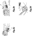
- the autonomous computation device is fixed to a structure of the interior of the vehicle cabin chosen from the dashboard of the vehicle or a pillar thereof which reduces vibrations, such that it is very rigidly fixed to the structure of the vehicle so that it can pick up the movements of the dynamics of the vehicle as exactly as possible and the effects of the vibrations are minimal. It must be mentioned that in some vehicles internal accelerometers are not precise enough to allow performing this function.
- a second aspect of the invention relates to using a method according to the first aspect for detecting behavioral changes of a driver, including: drowsiness, distraction, stressed states, states of inebriation or under the influence of drugs, using different physiological variables chosen from heart rate, breathing, perspiration and the dynamics and/or operating state of the vehicle.
- the system comprises at least one physiological sensor associated with the driver of the vehicle, intended for detecting a physiological state of the driver and supplying information relating to said physiological state to said autonomous computation device, and where said autonomous computation device and said physiological sensor, or an electronic system connected thereto, have wireless communication capacity, said physiological sensor or said electronic system connected thereto being intended for supplying said information relating to said physiological state to said autonomous computation device wirelessly.
- Figure 1 shows the system proposed by the third aspect of the invention for one embodiment for which the autonomous computation device D receives information from contact biological sensors Sbs, such as the plethysmographic band shown, from contactless biological sensors Sbc, such as the one included in the steering wheel of the vehicle shown which is communicated wirelessly with the module or electronic system included in the driver's seat, and from internal sensors inside the device D (not shown), such as those forming a three-axis gyroscope, an accelerometer, a proximity sensor and an environmental light sensor, which supply information that is used, as described above for a number of embodiments, for inferring the behavior or state of the driver of a vehicle according to the method of the first aspect of the invention.
- contact biological sensors Sbs such as the plethysmographic band shown
- contactless biological sensors Sbc such as the one included in the steering wheel of the vehicle shown which is communicated wirelessly with the module or electronic system included in the driver's seat
- internal sensors inside the device D not shown
- the device D
- the number and type of sensors is not limited to that shown, both in relation to biological sensors and to the internal sensors of the device D, being able to use, for example, in relation to the biological sensors, any type of known sensor for detecting breathing, heart rate, or any other physiological parameter of interest, such that a state of the driver that may affect driving, such as drowsiness, can be detected.
- the autonomous computation device D processes the information received from the different sensors and determines as a result (by implementing the method of the first aspect) if the behavior of the driver of the vehicle is abnormal, in which case a warning alarm signal is generated and sent to the driver (for example through his/her own autonomous computation device D) and/or to a server S accessed by a remote control center C and/or different computer terminals U1, U2 of the user or users.
- the wireless terminal could send the alarm signal to another telecommunications unit for transmitting the data to the remote control center.
- the device D sends to the server S part or all of the processed information and the result of said processing, such that both in the control center C and in the terminals U1, U2 said information can be analyzed and actions be taken accordingly.
- the display of the autonomous computation device D of Figure 1 graphically shows, for the embodiment shown, the attention state of the driver as a result of said processing of the information from the sensors, in the form of a series of bars that light up or change color in a higher or lower number depending on such attention state.
- Figures 2a to 2d show different assembly alternatives of the autonomous computation device D by means of fixing it to a structure of the interior of the vehicle cabin, Figure 2a showing the case when the device D is assembled by means of a support to the front of the vehicle, Figure 2b showing it assembled on the front windshield, Figure 2d showing it assembled by means of a support to a cup holder.
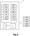
- Figure 3 schematically shows the inside of the autonomous computation device D, where a series of internal sensors of the device D have been depicted with references Si1 to Si14 connected to the processing means E, which in turn are connected to a memory M where the aforementioned reference information is stored.
- FIG 3 also shows a series of external sensors Sel to Se5 which are communicated wirelessly with the processing means E of the autonomous computation device D.
- Said external sensors Sel to Se5 include: a sensor associated with detecting the quality/type of road, a sensor associated with detecting biological information of the subject, a sensor associated with detecting the lines of the lane and a sensor associated with a system for detecting obstacles.
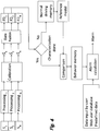
- Figure 4 schematically shows the different steps of the method of the first aspect of the invention for one embodiment, then explaining the different steps shown therein for the information from processing (Processing 1 to Processing n) signals S 1 , S 2 , S N provided by respective sensors, including at least one accelerometer and a gyroscope.
- the autonomous computation device D it is necessary for the working of the system and method of the present invention for the autonomous computation device D to be fixed to the structure of the vehicle and this fixing must have sufficient quality so that the vibrations caused by the motor or the different elements acting between the autonomous computation device D and the chassis of the vehicle do not distort the measurements taken by the sensors corresponding to the dynamics being followed by the vehicle.
- a possible solution consists of measuring the power of the total vibration and if said measurement exceeds a pre-established threshold, generating a message to the user indicating that the terminal is not correctly fixed.
- the autonomous computation device D has a display, the user will arrange it such that it allows him/her to view it correctly, so the orientation of the axes of the device and that of the forward movement of the vehicle may not coincide.
- the program implementing the method of the invention will initially estimate the rotation needed to align the axes of the device D with the axes of the vehicle and will apply said rotation to subsequent readings of the accelerometers and gyroscopes.
- Any inertial system requires aligning its axes with those of the forward movement direction of the vehicle. For this purpose it has information relating to the z axis or the axis perpendicular to the vehicle indicated by gravity and the direction which maximizes the traveled trajectory corresponding to the direction of motion or axis x. Once these two axes are identified, the axis y is obtained immediately. This identification is complicated by factors such as vibrations, the possibility that the vehicle is traveling on ramps and the presence of accelerations caused by not using a reference inertial system.
- a preferred method to follow for converting the axes would be the one proposed in the article Civilian Vehicle Navigation: Required Alignment of the Inertial Sensors for Acceptable Navigation Accuracies (Zainab F. Syed, Priyanka Aggarwal, Xiaoji Niu, and Naser The-Sheimy), which proposes a leveling method using the gyroscopes by balancing the specific forces of the accelerometers with those of the gyroscopes.
- the integration of the signals of the accelerometers allows estimating the speeds and the dual integration allows estimating the distance traveled.
- the angles of rotation are estimated by an optimization method which maximizes the distance traveled in an axis called the x axis and minimizes the distances in the perpendicular axes.
- a second optimization is based on assuming that gravity is basically perpendicular to the car.
- the speeds obtained with it can be compared with those obtained with the inertial system for performing a finer adjustment of the rotation matrix by means of using Kalman filters.
- Characteristics of interest that are subsequently fused into the block indicated as "Data Fusion" for evaluating a series of descriptive functions of the behavior or state of the driver are obtained from these signals ⁇ 1 , ⁇ 2 , ⁇ N , indicated in Figure 4 as FD 1 , FD 2 and FD N .
- non-observable signals moving elements of the steering wheel, of pedals, etc.
- observable signals S 1 , S 2 , S N i.e., those from the inertial sensors.
- S 1 , S 2 , S N i.e., those from the inertial sensors.
- One embodiment consists of predicting the signal of acceleration in the direction of the car, but also using the "pitch" gyroscope and the speed of the car obtained by GPS. Time series of these signals in a test phase are used to find this model and multivariate predictive regression models are built.
- the system characterizes the statistics of the descriptive functions FD 1 , FD 2 and FD N during initial driving periods, when certain conditions relating to speed of the vehicle, type of road, radii of curvature, presence or absence of overtaking maneuvers and lane changes, are met.
- Reference levels are extracted from the statistics obtained in the normal driving zones during said characterization.
- Normal driving memory and “Reference model” are representative of said characterization, reference levels extracted from the statistics obtained in normal driving zones being recorded in said memory, a reference model being created with said reference levels.
- the descriptive functions are evaluated from the treating of the linear and angular acceleration signals once rotated with respect to the reference framework corresponding to the vehicle. It is possible to estimate the trajectory of the vehicle based on the inertial sensors and by means of using Kalman filters. Descriptive functions characterizing driving can be extracted based on this estimation in segments having a limited duration (of the order of a minute). Examples of these descriptive functions are: standard deviation of the lateral position of the car, entropy of the lateral deviation, number of zigzags, frequency of zigzags, maximum lateral speed, mean lateral speed, maximum acceleration in the direction of motion, mean speed, maximum speed variation, number of peaks in angular acceleration, etc.
- the system fuses a plurality of descriptive functions FD 1 , FD 2 and FD N and compares the combined value or values obtained upon evaluating them based on the fused data of signals ⁇ 1 , ⁇ 2 , ⁇ N , comparing them with reference values obtained in the phase of characterization to detect degradations in the behavior of the driver.
- the discrepancy values generated are stored in a memory (indicated in Figure 4 as behavior memory), the evolution and magnitude over time being analyzed for generating a warning alarm signal, a function which is performed in the block indicated as "Alarm calculation”.
- the system takes additional variables into account, such as the time of day and driving time, to adjust the sensitivity of the abnormal driving detector, as well as taking into account a series of additional data supplied to the block "Alarm calculation", from the block shown on the left, including data input by the user from a web user database and/or predefined data.
- a warning alarm is sent to the driver and/or to a remote control center where it is collected in a selectively accessible database together with at least trajectory and date data.
- this information of the abnormal driver behavior alarm associated with the trajectory is combined with the journey time information, stop times, time of the day, km traveled and that it is graphically displayed on a map.
- Another strategy for warning the driver consists of making an automatic call to a number stored in the memory of the autonomous processing device.
Landscapes
- Business, Economics & Management (AREA)
- Emergency Management (AREA)
- Physics & Mathematics (AREA)
- General Physics & Mathematics (AREA)
- Engineering & Computer Science (AREA)
- Automation & Control Theory (AREA)
- Mechanical Engineering (AREA)
- Traffic Control Systems (AREA)
- Navigation (AREA)
Claims (13)
- Verfahren zur Bestimmung des Verhaltens des Fahrers eines Fahrzeugs mit Hilfe von einer Berechnungsvorrichtung, welche sich im Fahrzeug befindet und Sensoren integriert, welche von der Bewegung und dem Betriebszustand des Fahrzeugs berichten können, wobei die genannten Sensoren Trägheitssensoren sind, welche Beschleunigungsmesser und/oder Gyroskope umfassen, und wobei das Verfahren Folgendes umfasst:a) Verarbeiten mindestens eines Teils der Information aus einem oder mehreren der genannten Trägheitssensoren der genannten Berechnungsvorrichtung, eins nach dem anderen oder in Kombination, um eine Vielzahl von beschreibenden Funktionen der Wechselwirkungsbedingungen oder des Verhaltens des Fahrers mit dem Fahrzeug im Laufe der Zeit, in jeder Phase einer Bewegungsbahn und für eine spezifische Straße, zu bewerten; undb) Bestimmen des genannten Verhaltens unter Vergleichung der Bewertung der genannten beschreibenden Funktionen, oder mindestens eines Wertes derselben, mit Referenzinformation, welche mit einem Verhalten des Fahrers assoziiert ist, welches als ein normales Verhalten für die genannte spezifische Straße betrachtet wird, wobei die genannte Referenzinformation in mindestens einem Speicher der genannten Berechnungsvorrichtung, oder in einer Fernvorrichtung oder einem Datenbank gespeichert wird, wobei die genannte Referenzinformation Referenzwerte umfasst, welche mittels der Bewertung der genannten mindestens einen beschreibenden Funktion, in Charakterisierungsperioden und in Zonen, in welchen spezifische Bedingungen bezüglich der Geschwindigkeit des Fahrzeugs und/oder des Krümmungsradius erfüllt werden, erhalten werden; undc) Feststellen dass das Verhalten anormal ist, in Abhängigkeit einer Bewertung der Ergebnisse aus Schritt b),dadurch gekennzeichnet, dass das Verfahren Folgendes umfasst:- Verwenden als die genannte Berechnungsvorrichtung einer selbstständigen Berechnungsvorrichtung mit Telekommunikationsfähigkeit, welche die genannten Trägheitssensoren integriert, welche von der Bewegung und dem Betriebszustand des Fahrzeugs berichten können; und- vor den genannten Schritten a) bis c), Befestigen der genannten selbstständigen Berechnungsvorrichtung an einer Struktur des Inneren der Fahrzeugkabine, ausgewählt aus dem Armaturenbrett des Fahrzeugs oder einem Pfeiler desselben, welcher die Vibrationen verringert, und das Kalibrieren mindestens der inneren Sensoren der selbstständigen Berechnungsvorrichtung, und ferner Folgendes umfasst:- Empfangen, durch die genannte selbstständige Berechnungsvorrichtung, von Information aus mindestens einem der folgenden zusätzlichen Sensoren, welche extern zur selbstständigen Vorrichtung sind: Empfänger/Ortungsgerät basierend auf einem globalen Navigationssatellitensystem, Temperatursensor, mit der Geschwindigkeit assoziiertem Sensor, Kompass, mit der Erfassung von Krümmungsradien assoziiertem Sensor, mit der Erfassung der Fahrbahnbreite assoziiertem Sensor, mit der Erfassung der Qualität und/oder des Straßentyps assoziiertem Sensor, Höhensensor, mit einem System zur Erfassung von Hindernissen oder der Verlassung der Fahrbahn assoziiertem Sensor oder eine Kombination derselben.
- Verfahren nach Anspruch 1, wobei es die Bestimmung umfasst, dass das Verhalten des Fahrers des Fahrzeugs anormal ist, wenn das Ergebnis des genannten Vergleichens aus Schritt b) mindestens eine Abweichung bietet, welche größer als ein spezifischer Abweichungswert ist, und das Erzeugen eines Warnalarmsignals, wenn ein Abweichungsprotokoll eine anormale Fahrabstandsfrequenz zeigt, welche größer als eine spezifische Frequenz ist.
- Verfahren nach einem der vorhergehenden Ansprüche, wobei die genannte Bestimmung des Verhaltens oder Zustandes des Fahrers unter zusätzlicher Betrachtung der Verarbeitung der physiologischen Information des Fahrers und unter Durchführung einer gemeinsamen Bewertung bestimmt wird.
- Verfahren nach Anspruch 3, wobei es Folgendes umfasst:- Vergleichen der genannten Information über den physiologischen Zustand des Fahrers mit Referenzwerten bezüglich eines physiologischen Zustandes des Fahrers, welcher mit einem Verhalten des Fahrers assoziiert ist, welches als normal betrachtet wird, wobei die genannten Referenzwerte in einem Speicher der physiologischen Sensorvorrichtung, in einem Speicher der selbstständigen Berechnungsvorrichtung oder in einer Fernvorrichtung gespeichert werden, und- Feststellen dass das Verhalten des Fahrers des Fahrzeugs anormal ist, wenn das Ergebnis des genannten Vergleichens der Information über den physiologischen Zustand des Fahrers mindestens eine Abweichung bietet, welche größer als ein spezifischer Abweichungswert ist, und das Erzeugen eines Warnalarmsignals mindestens für den Fahrer, wenn es bestimmt wird, dass ein Abweichungsprotokoll eine anormale Sequenz zeigt.
- Verfahren nach Anspruch 4, wobei es das Erzeugen der genannten Referenzwerte bezüglich eines physiologischen Zustandes des Fahrers umfasst, mittels eines anfänglichen Charakterisierungsprozesses, umfassend dass ein Benutzer eine Datenanweisung über seinen/ihren Zustand zu einem spezifischen Zeitpunkt und Gewohnheiten über eine Eingabe der selbstständigen Berechnungsvorrichtung bereitstellt, oder mittels der standardmäßigen Einbeziehung derselben in einem Computerprogramm, welches in der selbstständigen Vorrichtung installiert ist, oder über einen Datenbank oder einen mit dem Benutzer assoziierten Sensor, umfassend mehrere zuvor festgestellte Zustände, und das Durchführen der genannten Erzeugung von Werten für jeden einer Vielzahl von Fahrern und/oder Fahrprofilen und/oder Betriebsumgebungen umfassend Daten über die gefahrene Straße.
- Verfahren nach Anspruch 5, wobei die Kohärenz der von einem Benutzer eingegebenen Daten gegen das Verhalten des genannten Benutzers geprüft wird, welches über die Dynamik und/oder den Betriebszustand des Fahrzeugs oder über seine/ihre biologischen Daten für eine Prüfperiode bestimmt wird, welche eine vorbestimmte Dauer hat.
- Verfahren nach Anspruch 1, wobei es das Durchführen eines vorherigen Schrittes des Kalibrierens mindestens der inneren Sensoren der selbstständigen Berechnungsvorrichtung umfasst, und wobei, wenn während des normalen Betriebsmodus, die selbstständige Berechnungsvorrichtung identifiziert, dass einer oder mehr der Sensoren Werte bereitstellen, welche außerhalb der Erwarteten liegen, diesen vorläufig ein niedrigeres Gewicht in Bezug auf die Dynamik und/oder den Betriebszustand des Fahrzeugs zugeordnet wird, von welchem der jeweilige Sensor berichtet.
- Verfahren nach Anspruch 1, wobei die genannte beschreibende Funktion mindestens eine der folgenden beschreibenden Funktionen ist: Standardabweichung der seitlichen Stellung des Autos, Entropie der seitlichen Abweichung, Anzahl der Zickzacks, Frequenz der Zickzacks, maximale seitliche Geschwindigkeit, mittlere seitliche Geschwindigkeit, maximale Beschleunigung in Richtung der Bewegung, mittlere Geschwindigkeit, maximale Geschwindigkeitsvariation, Anzahl von Scheiteln in der Winkelbeschleunigung und Anzahl und Intensität der Längs- und Querneigungen, oder eine Kombination derselben.
- Verfahren nach Anspruch 1, wobei die genannte selbstständige Berechnungsvorrichtung aus einem Mobiltelefon oder einem PDA ausgewählt wird.
- Verwendung eines Verfahrens nach einem der vorhergehenden Ansprüche, zum Detektieren von Verhaltensänderungen eines Fahrers umfassend: Schläfrigkeit, Ablenkung, gestresste Zustände, Zustände des Rausches oder unter dem Einfluss von Drogen, unter Verwendung von unterschiedlichen physiologischen Variablen, ausgewählt aus Herzfrequenz, Atmung, Transpiration und der Dynamik und/oder dem Betriebszustand des Fahrzeugs.
- System zur Bestimmung des Verhaltens des Fahrers eines Fahrzeugs, umfassend:- Verarbeitungsmittel (E); und- innere Sensoren (Si1-Si14), welche mit den genannten Verarbeitungsmitteln (E) verbunden sind und derart angeordnet sind, um den Zustand des Fahrzeugs zu detektieren und Information bezüglich des genannten Zustandes des Fahrzeugs den genannten Verarbeitungsmitteln (E) zuzuführen;wobei das System dadurch gekennzeichnet ist, dass:- die genannten Verarbeitungsmittel und die inneren Sensoren innerhalb einer selbstständigen Berechnungsvorrichtung (D) mit Telekommunikationsfähigkeit sind, welche an einer Struktur des Inneren der Fahrzeugkabine befestigt ist, ausgewählt aus dem Armaturenbrett des Fahrzeugs oder einem Pfeiler desselben, welcher die Vibrationen verringert, wobei die selbstständige Berechnungsvorrichtung einen Speicher (M) umfasst, in welchem mindestens Referenzinformation bezüglich der Zustände des Fahrzeugs, welche mit einem Verhalten des Fahrers assoziiert werden, welches als normal betrachtet wird, aufgenommen wird; und- dass die genannten Verarbeitungsmittel (E) mit dem Speicher (M) kommuniziert werden, um Zugriff zur genannten Referenzinformation zu haben, und sie sind dazu angepasst, das Verfahren nach einem der Ansprüche 1 bis 9 zu verwirklichen.
- System nach Anspruch 11, wobei es ferner mindestens einen mit dem Fahrer des Fahrzeugs assoziierten physiologischen Sensor (Sbs, Sbc) umfasst, welcher dazu bestimmt ist, einen physiologischen Zustand des Fahrers zu detektieren und dazu angepasst, Information bezüglich des genannten physiologischen Zustands der genannten selbstständigen Berechnungsvorrichtung (D) zuzuführen, und wobei die genannte selbstständige Berechnungsvorrichtung (D) und der genannte mindestens eine physiologische Sensor (Sbs, Sbc), oder ein damit verbundenes elektronisches System, drahtlose Kommunikationsfähigkeit haben, wobei der genannte mindestens eine physiologische Sensor (Sbs, Sbc), oder das damit verbundene elektronische System, dafür bestimmt ist, die genannte Information bezüglich des genannten physiologischen Zustands der genannten selbstständigen Berechnungsvorrichtung (D) drahtlos zuzuführen.
- Computerprogramm umfassend Computerprogrammcodiermittel, geeignet für die Durchführung der Schritte des Verfahrens nach einem der Ansprüche 1 bis 9, umfassend die genannte Bewertung der beschreibenden Funktionen der Wechselwirkung des Fahrers mit dem Fahrzeug, in jeder Phase einer Bewegungsbahn, und die Behandlung der Information über den physiologischen Zustand des Fahrers und die genannte Bestimmung des Verhaltens oder Zustandes des Fahrers des Fahrzeugs, wenn das zuvor erwähnte Programm in einem Computer, einem digitalen Signalprozessor, einem anwendungsspezifischen integrierten Schaltkreis, einem Mikroprozessor, einem Mikrocontroller oder jeder anderen Form von programmierbarem Hardware ausgeführt wird.
Applications Claiming Priority (1)
| Application Number | Priority Date | Filing Date | Title |
|---|---|---|---|
| PCT/ES2012/000024 WO2013113947A1 (es) | 2012-02-01 | 2012-02-01 | Método y sistema para inferir el comportamiento o estado del conductor de un vehículo, uso del método y programa informático para llevar a cabo el método |
Publications (2)
| Publication Number | Publication Date |
|---|---|
| EP2811474A1 EP2811474A1 (de) | 2014-12-10 |
| EP2811474B1 true EP2811474B1 (de) | 2018-08-08 |
Family
ID=45976958
Family Applications (1)
| Application Number | Title | Priority Date | Filing Date |
|---|---|---|---|
| EP12715409.4A Not-in-force EP2811474B1 (de) | 2012-02-01 | 2012-02-01 | Verfahren und system zur bestimmung des verhaltens oder zustandes des fahrers eines fahrzeugs, verwendungsverfahren und computerprogramm zur durchführung des verfahrens |
Country Status (3)
| Country | Link |
|---|---|
| US (1) | US9663047B2 (de) |
| EP (1) | EP2811474B1 (de) |
| WO (1) | WO2013113947A1 (de) |
Families Citing this family (33)
| Publication number | Priority date | Publication date | Assignee | Title |
|---|---|---|---|---|
| US10706647B2 (en) * | 2010-12-02 | 2020-07-07 | Zonar Systems, Inc. | Method and apparatus for implementing a vehicle inspection waiver program |
| US10431020B2 (en) | 2010-12-02 | 2019-10-01 | Zonar Systems, Inc. | Method and apparatus for implementing a vehicle inspection waiver program |
| US9292471B2 (en) | 2011-02-18 | 2016-03-22 | Honda Motor Co., Ltd. | Coordinated vehicle response system and method for driver behavior |
| US8698639B2 (en) | 2011-02-18 | 2014-04-15 | Honda Motor Co., Ltd. | System and method for responding to driver behavior |
| EP2811474B1 (de) | 2012-02-01 | 2018-08-08 | Fico Mirrors, SA | Verfahren und system zur bestimmung des verhaltens oder zustandes des fahrers eines fahrzeugs, verwendungsverfahren und computerprogramm zur durchführung des verfahrens |
| US9352751B2 (en) | 2014-06-23 | 2016-05-31 | Honda Motor Co., Ltd. | System and method for determining the information transfer rate between a driver and vehicle |
| US9751534B2 (en) | 2013-03-15 | 2017-09-05 | Honda Motor Co., Ltd. | System and method for responding to driver state |
| US10499856B2 (en) | 2013-04-06 | 2019-12-10 | Honda Motor Co., Ltd. | System and method for biological signal processing with highly auto-correlated carrier sequences |
| US10077055B2 (en) | 2014-06-23 | 2018-09-18 | Honda Motor Co., Ltd. | System and method for determining the information transfer rate between a driver and vehicle |
| US9386401B2 (en) * | 2014-08-25 | 2016-07-05 | Steven K. Gold | Proximity-based sensing, communicating, and processing of user physiologic information |
| US20180227735A1 (en) | 2014-08-25 | 2018-08-09 | Phyziio, Inc. | Proximity-Based Attribution of Rewards |
| US10325167B1 (en) * | 2015-01-13 | 2019-06-18 | State Farm Mutual Automobile Insurance Company | Apparatuses, systems and methods for generating data representative of vehicle driver ratings |
| US10909462B2 (en) * | 2015-05-21 | 2021-02-02 | Tata Consultancy Services Limited | Multi-dimensional sensor data based human behaviour determination system and method |
| DE102015209588B3 (de) * | 2015-05-26 | 2016-10-06 | Lisa Dräxlmaier GmbH | Vorrichtung und Verfahren zum Erkennen von Störungen in einem Bordnetz |
| DE102016222693A1 (de) * | 2015-11-24 | 2017-05-24 | Hyundai Dymos Incorporated | Messsystem für ein biologisches Signal basierend auf einer Fahrumgebung für einen Fahrzeugsitz |
| KR101834349B1 (ko) * | 2016-01-08 | 2018-03-05 | 엘지전자 주식회사 | 조향 장치 및 차량 |
| CN105835797A (zh) * | 2016-02-22 | 2016-08-10 | 乐卡汽车智能科技(北京)有限公司 | 车辆状态监控方法及装置 |
| US10293830B2 (en) | 2016-11-07 | 2019-05-21 | Honeywell International Inc. | Systems and methods for recognizing and analyzing emotional states of a vehicle operator |
| CN109996713B (zh) * | 2016-11-28 | 2022-04-15 | 本田技研工业株式会社 | 驾驶辅助装置、驾驶辅助系统和驾驶辅助装置的控制方法 |
| JP6895634B2 (ja) * | 2016-12-16 | 2021-06-30 | パナソニックIpマネジメント株式会社 | 情報処理システム、情報処理方法、およびプログラム |
| US10528830B2 (en) * | 2017-06-11 | 2020-01-07 | Jungo Connectivity Ltd. | System and method for remote monitoring of a human |
| US11300649B1 (en) * | 2017-06-24 | 2022-04-12 | Robotic Research Opco, Llc | Vehicle localization augmentation for dismounts |
| US10514696B2 (en) | 2017-07-21 | 2019-12-24 | Here Global B.V. | Navigation driving metric |
| RU2686556C1 (ru) * | 2017-12-20 | 2019-04-29 | Федеральное государственное унитарное предприятие "Центральный ордена Трудового Красного Знамени научно-исследовательский автомобильный и автомоторный институт "НАМИ" (ФГУП "НАМИ") | Способ контроля состояния бодрствования водителя автомобиля |
| RU2671891C1 (ru) * | 2017-12-20 | 2018-11-07 | Федеральное государственное унитарное предприятие "Центральный ордена Трудового Красного Знамени научно-исследовательский автомобильный и автомоторный институт "НАМИ" (ФГУП "НАМИ") | Система контроля состояния бодрствования водителя автомобиля |
| JP6977589B2 (ja) * | 2018-01-31 | 2021-12-08 | 株式会社デンソー | 車両用警報装置 |
| US10909866B2 (en) | 2018-07-20 | 2021-02-02 | Cybernet Systems Corp. | Autonomous transportation system and methods |
| US11180158B1 (en) * | 2018-07-31 | 2021-11-23 | United Services Automobile Association (Usaa) | Routing or driving systems and methods based on sleep pattern information |
| CN109032116A (zh) * | 2018-08-30 | 2018-12-18 | 百度在线网络技术(北京)有限公司 | 车辆故障处理方法、装置、设备及存储介质 |
| US11577734B2 (en) | 2018-12-20 | 2023-02-14 | Nauto, Inc. | System and method for analysis of driver behavior |
| US11267482B2 (en) | 2019-10-11 | 2022-03-08 | International Business Machines Corporation | Mitigating risk behaviors |
| CN110874355B (zh) * | 2019-11-28 | 2022-08-23 | 以萨技术股份有限公司 | 车辆徘徊绕圈异常行为的检测方法、系统、终端及介质 |
| CN112959960A (zh) * | 2021-02-26 | 2021-06-15 | 北京车和家信息技术有限公司 | 异常用车检测方法和装置、介质、设备、车辆、服务器 |
Citations (6)
| Publication number | Priority date | Publication date | Assignee | Title |
|---|---|---|---|---|
| US5832400A (en) * | 1994-09-05 | 1998-11-03 | Nissan Motor Co.., Ltd. | Controlling vehicular driving force in anticipation of road situation on which vehicle is to run utilizing vehicular navigation system |
| WO2005050522A1 (en) * | 2003-11-20 | 2005-06-02 | Volvo Technology Corporation | Method and system for communication and/or interaction between a vehicle driver and a plurality of applications |
| US20060214807A1 (en) * | 2005-03-24 | 2006-09-28 | Tengshe Vishwas V | Drowsy driving alarm system |
| US20070290867A1 (en) * | 2006-06-15 | 2007-12-20 | The Yokohama Rubber Co., Ltd. | Apparatus and method for evaluating driving skill and apparatus and method for informing efficiency of driver's physical load to driving operation |
| EP2204784A1 (de) * | 2008-12-31 | 2010-07-07 | MAGNETI MARELLI SISTEMI ELETTRONICI S.p.A. | System und Verfahren zur Überwachung des Wachsamkeitszustands des Fahrers eines Fahrzeugs |
| US20110029184A1 (en) * | 2009-07-31 | 2011-02-03 | Systems and Advances Technologies Engineering S.r.I. (S.A.T.E.) | Road Vehicle Drive Behaviour Analysis Method |
Family Cites Families (8)
| Publication number | Priority date | Publication date | Assignee | Title |
|---|---|---|---|---|
| US9290146B2 (en) * | 1992-05-05 | 2016-03-22 | Intelligent Technologies International, Inc. | Optical monitoring of vehicle interiors |
| SE0002804D0 (sv) * | 2000-08-01 | 2000-08-01 | Promind Ab | Teknik för att fortlöpande kartlägga fordons/förares uppträdande/beteende för att fastställa fordons reaktionskoefficient resp. förares kompetenskoefficient, samt anordning för grafisk presentation av dessa koefficienter |
| US6909947B2 (en) * | 2000-10-14 | 2005-06-21 | Motorola, Inc. | System and method for driver performance improvement |
| US7138922B2 (en) | 2003-03-18 | 2006-11-21 | Ford Global Technologies, Llc | Drowsy driver monitoring and prevention system |
| JP2005034520A (ja) | 2003-07-18 | 2005-02-10 | Tokai Rika Co Ltd | 体調監視システム |
| US7482937B2 (en) | 2006-03-24 | 2009-01-27 | Motorola, Inc. | Vision based alert system using portable device with camera |
| US8630768B2 (en) * | 2006-05-22 | 2014-01-14 | Inthinc Technology Solutions, Inc. | System and method for monitoring vehicle parameters and driver behavior |
| EP2811474B1 (de) | 2012-02-01 | 2018-08-08 | Fico Mirrors, SA | Verfahren und system zur bestimmung des verhaltens oder zustandes des fahrers eines fahrzeugs, verwendungsverfahren und computerprogramm zur durchführung des verfahrens |
-
2012
- 2012-02-01 EP EP12715409.4A patent/EP2811474B1/de not_active Not-in-force
- 2012-02-01 US US14/376,020 patent/US9663047B2/en active Active
- 2012-02-01 WO PCT/ES2012/000024 patent/WO2013113947A1/es active Application Filing
Patent Citations (6)
| Publication number | Priority date | Publication date | Assignee | Title |
|---|---|---|---|---|
| US5832400A (en) * | 1994-09-05 | 1998-11-03 | Nissan Motor Co.., Ltd. | Controlling vehicular driving force in anticipation of road situation on which vehicle is to run utilizing vehicular navigation system |
| WO2005050522A1 (en) * | 2003-11-20 | 2005-06-02 | Volvo Technology Corporation | Method and system for communication and/or interaction between a vehicle driver and a plurality of applications |
| US20060214807A1 (en) * | 2005-03-24 | 2006-09-28 | Tengshe Vishwas V | Drowsy driving alarm system |
| US20070290867A1 (en) * | 2006-06-15 | 2007-12-20 | The Yokohama Rubber Co., Ltd. | Apparatus and method for evaluating driving skill and apparatus and method for informing efficiency of driver's physical load to driving operation |
| EP2204784A1 (de) * | 2008-12-31 | 2010-07-07 | MAGNETI MARELLI SISTEMI ELETTRONICI S.p.A. | System und Verfahren zur Überwachung des Wachsamkeitszustands des Fahrers eines Fahrzeugs |
| US20110029184A1 (en) * | 2009-07-31 | 2011-02-03 | Systems and Advances Technologies Engineering S.r.I. (S.A.T.E.) | Road Vehicle Drive Behaviour Analysis Method |
Also Published As
| Publication number | Publication date |
|---|---|
| WO2013113947A8 (es) | 2014-10-02 |
| US20150029014A1 (en) | 2015-01-29 |
| US9663047B2 (en) | 2017-05-30 |
| WO2013113947A1 (es) | 2013-08-08 |
| EP2811474A1 (de) | 2014-12-10 |
Similar Documents
| Publication | Publication Date | Title |
|---|---|---|
| EP2811474B1 (de) | Verfahren und system zur bestimmung des verhaltens oder zustandes des fahrers eines fahrzeugs, verwendungsverfahren und computerprogramm zur durchführung des verfahrens | |
| US9676395B2 (en) | Incapacitated driving detection and prevention | |
| CN104656503B (zh) | 自主车辆中的可穿戴计算机 | |
| EP3239011A1 (de) | Vorrichtung zur schätzung des fahrbewusstseinszustands | |
| CN110505837A (zh) | 信息处理设备、信息处理方法和程序 | |
| CN115768671A (zh) | 用于自主交通工具的晕动症检测系统 | |
| US10528833B1 (en) | Health monitoring system operable in a vehicle environment | |
| CN106043299A (zh) | 车辆控制装置 | |
| US20130316310A1 (en) | Methods for determining orientation of a moving vehicle | |
| JP2015513131A (ja) | 運転行動の危険指標の算出装置、システムおよび方法 | |
| CN102168977A (zh) | 使用全球定位系统的车轮定位诊断 | |
| US10845802B2 (en) | Method for operating a motor vehicle | |
| CN113009540B (zh) | 一种基于组合导航的驾驶行为监测系统及方法 | |
| CN109890662A (zh) | 车辆控制系统、车辆控制方法及车辆控制程序 | |
| JP6375873B2 (ja) | ドライバ状態診断装置 | |
| CN106228751A (zh) | 基于安卓平台mems/磁传感器/gps的跌倒智能报警系统与方法 | |
| CN111971218A (zh) | 驾驶员轮廓分析和识别 | |
| US20230051377A1 (en) | Mobility movemennt information acquiring method and mobility movement information acquiring apparatus | |
| JP7114953B2 (ja) | 車載機、運転評価装置、これらを備えた運転評価システム、データ送信方法、及びデータ送信プログラム | |
| WO2015189434A1 (en) | System or method for evaluation of the guide and comfort | |
| KR20110066883A (ko) | 지능형 차량 사고 경고 장치 | |
| JPWO2020085223A1 (ja) | 情報処理方法、情報処理装置、情報処理プログラム及び情報処理システム | |
| JP2021027909A (ja) | 車両用情報提供システム、車両用情報提供方法、情報提供装置、およびプログラム | |
| US20240054826A1 (en) | Mount security detection method | |
| KR101456561B1 (ko) | 차량 상태 정보 처리 시스템 및 방법 |
Legal Events
| Date | Code | Title | Description |
|---|---|---|---|
| PUAI | Public reference made under article 153(3) epc to a published international application that has entered the european phase |
Free format text: ORIGINAL CODE: 0009012 |
|
| 17P | Request for examination filed |
Effective date: 20140814 |
|
| AK | Designated contracting states |
Kind code of ref document: A1 Designated state(s): AL AT BE BG CH CY CZ DE DK EE ES FI FR GB GR HR HU IE IS IT LI LT LU LV MC MK MT NL NO PL PT RO RS SE SI SK SM TR |
|
| AX | Request for extension of the european patent |
Extension state: BA ME |
|
| DAX | Request for extension of the european patent (deleted) | ||
| 17Q | First examination report despatched |
Effective date: 20151028 |
|
| GRAP | Despatch of communication of intention to grant a patent |
Free format text: ORIGINAL CODE: EPIDOSNIGR1 |
|
| STAA | Information on the status of an ep patent application or granted ep patent |
Free format text: STATUS: GRANT OF PATENT IS INTENDED |
|
| INTG | Intention to grant announced |
Effective date: 20180228 |
|
| GRAS | Grant fee paid |
Free format text: ORIGINAL CODE: EPIDOSNIGR3 |
|
| GRAA | (expected) grant |
Free format text: ORIGINAL CODE: 0009210 |
|
| STAA | Information on the status of an ep patent application or granted ep patent |
Free format text: STATUS: THE PATENT HAS BEEN GRANTED |
|
| AK | Designated contracting states |
Kind code of ref document: B1 Designated state(s): AL AT BE BG CH CY CZ DE DK EE ES FI FR GB GR HR HU IE IS IT LI LT LU LV MC MK MT NL NO PL PT RO RS SE SI SK SM TR |
|
| REG | Reference to a national code |
Ref country code: GB Ref legal event code: FG4D |
|
| REG | Reference to a national code |
Ref country code: CH Ref legal event code: EP Ref country code: AT Ref legal event code: REF Ref document number: 1027907 Country of ref document: AT Kind code of ref document: T Effective date: 20180815 |
|
| REG | Reference to a national code |
Ref country code: IE Ref legal event code: FG4D |
|
| REG | Reference to a national code |
Ref country code: DE Ref legal event code: R096 Ref document number: 602012049427 Country of ref document: DE |
|
| REG | Reference to a national code |
Ref country code: NL Ref legal event code: MP Effective date: 20180808 |
|
| REG | Reference to a national code |
Ref country code: LT Ref legal event code: MG4D |
|
| REG | Reference to a national code |
Ref country code: AT Ref legal event code: MK05 Ref document number: 1027907 Country of ref document: AT Kind code of ref document: T Effective date: 20180808 |
|
| PG25 | Lapsed in a contracting state [announced via postgrant information from national office to epo] |
Ref country code: PL Free format text: LAPSE BECAUSE OF FAILURE TO SUBMIT A TRANSLATION OF THE DESCRIPTION OR TO PAY THE FEE WITHIN THE PRESCRIBED TIME-LIMIT Effective date: 20180808 Ref country code: RS Free format text: LAPSE BECAUSE OF FAILURE TO SUBMIT A TRANSLATION OF THE DESCRIPTION OR TO PAY THE FEE WITHIN THE PRESCRIBED TIME-LIMIT Effective date: 20180808 Ref country code: FI Free format text: LAPSE BECAUSE OF FAILURE TO SUBMIT A TRANSLATION OF THE DESCRIPTION OR TO PAY THE FEE WITHIN THE PRESCRIBED TIME-LIMIT Effective date: 20180808 Ref country code: LT Free format text: LAPSE BECAUSE OF FAILURE TO SUBMIT A TRANSLATION OF THE DESCRIPTION OR TO PAY THE FEE WITHIN THE PRESCRIBED TIME-LIMIT Effective date: 20180808 Ref country code: BG Free format text: LAPSE BECAUSE OF FAILURE TO SUBMIT A TRANSLATION OF THE DESCRIPTION OR TO PAY THE FEE WITHIN THE PRESCRIBED TIME-LIMIT Effective date: 20181108 Ref country code: AT Free format text: LAPSE BECAUSE OF FAILURE TO SUBMIT A TRANSLATION OF THE DESCRIPTION OR TO PAY THE FEE WITHIN THE PRESCRIBED TIME-LIMIT Effective date: 20180808 Ref country code: NO Free format text: LAPSE BECAUSE OF FAILURE TO SUBMIT A TRANSLATION OF THE DESCRIPTION OR TO PAY THE FEE WITHIN THE PRESCRIBED TIME-LIMIT Effective date: 20181108 Ref country code: NL Free format text: LAPSE BECAUSE OF FAILURE TO SUBMIT A TRANSLATION OF THE DESCRIPTION OR TO PAY THE FEE WITHIN THE PRESCRIBED TIME-LIMIT Effective date: 20180808 Ref country code: IS Free format text: LAPSE BECAUSE OF FAILURE TO SUBMIT A TRANSLATION OF THE DESCRIPTION OR TO PAY THE FEE WITHIN THE PRESCRIBED TIME-LIMIT Effective date: 20181208 Ref country code: GR Free format text: LAPSE BECAUSE OF FAILURE TO SUBMIT A TRANSLATION OF THE DESCRIPTION OR TO PAY THE FEE WITHIN THE PRESCRIBED TIME-LIMIT Effective date: 20181109 Ref country code: SE Free format text: LAPSE BECAUSE OF FAILURE TO SUBMIT A TRANSLATION OF THE DESCRIPTION OR TO PAY THE FEE WITHIN THE PRESCRIBED TIME-LIMIT Effective date: 20180808 |
|
| PG25 | Lapsed in a contracting state [announced via postgrant information from national office to epo] |
Ref country code: HR Free format text: LAPSE BECAUSE OF FAILURE TO SUBMIT A TRANSLATION OF THE DESCRIPTION OR TO PAY THE FEE WITHIN THE PRESCRIBED TIME-LIMIT Effective date: 20180808 Ref country code: LV Free format text: LAPSE BECAUSE OF FAILURE TO SUBMIT A TRANSLATION OF THE DESCRIPTION OR TO PAY THE FEE WITHIN THE PRESCRIBED TIME-LIMIT Effective date: 20180808 Ref country code: AL Free format text: LAPSE BECAUSE OF FAILURE TO SUBMIT A TRANSLATION OF THE DESCRIPTION OR TO PAY THE FEE WITHIN THE PRESCRIBED TIME-LIMIT Effective date: 20180808 |
|
| PG25 | Lapsed in a contracting state [announced via postgrant information from national office to epo] |
Ref country code: CZ Free format text: LAPSE BECAUSE OF FAILURE TO SUBMIT A TRANSLATION OF THE DESCRIPTION OR TO PAY THE FEE WITHIN THE PRESCRIBED TIME-LIMIT Effective date: 20180808 Ref country code: IT Free format text: LAPSE BECAUSE OF FAILURE TO SUBMIT A TRANSLATION OF THE DESCRIPTION OR TO PAY THE FEE WITHIN THE PRESCRIBED TIME-LIMIT Effective date: 20180808 Ref country code: EE Free format text: LAPSE BECAUSE OF FAILURE TO SUBMIT A TRANSLATION OF THE DESCRIPTION OR TO PAY THE FEE WITHIN THE PRESCRIBED TIME-LIMIT Effective date: 20180808 Ref country code: ES Free format text: LAPSE BECAUSE OF FAILURE TO SUBMIT A TRANSLATION OF THE DESCRIPTION OR TO PAY THE FEE WITHIN THE PRESCRIBED TIME-LIMIT Effective date: 20180808 Ref country code: RO Free format text: LAPSE BECAUSE OF FAILURE TO SUBMIT A TRANSLATION OF THE DESCRIPTION OR TO PAY THE FEE WITHIN THE PRESCRIBED TIME-LIMIT Effective date: 20180808 |
|
| REG | Reference to a national code |
Ref country code: DE Ref legal event code: R097 Ref document number: 602012049427 Country of ref document: DE |
|
| PG25 | Lapsed in a contracting state [announced via postgrant information from national office to epo] |
Ref country code: DK Free format text: LAPSE BECAUSE OF FAILURE TO SUBMIT A TRANSLATION OF THE DESCRIPTION OR TO PAY THE FEE WITHIN THE PRESCRIBED TIME-LIMIT Effective date: 20180808 Ref country code: SM Free format text: LAPSE BECAUSE OF FAILURE TO SUBMIT A TRANSLATION OF THE DESCRIPTION OR TO PAY THE FEE WITHIN THE PRESCRIBED TIME-LIMIT Effective date: 20180808 Ref country code: SK Free format text: LAPSE BECAUSE OF FAILURE TO SUBMIT A TRANSLATION OF THE DESCRIPTION OR TO PAY THE FEE WITHIN THE PRESCRIBED TIME-LIMIT Effective date: 20180808 |
|
| PLBE | No opposition filed within time limit |
Free format text: ORIGINAL CODE: 0009261 |
|
| STAA | Information on the status of an ep patent application or granted ep patent |
Free format text: STATUS: NO OPPOSITION FILED WITHIN TIME LIMIT |
|
| 26N | No opposition filed |
Effective date: 20190509 |
|
| PG25 | Lapsed in a contracting state [announced via postgrant information from national office to epo] |
Ref country code: SI Free format text: LAPSE BECAUSE OF FAILURE TO SUBMIT A TRANSLATION OF THE DESCRIPTION OR TO PAY THE FEE WITHIN THE PRESCRIBED TIME-LIMIT Effective date: 20180808 |
|
| REG | Reference to a national code |
Ref country code: CH Ref legal event code: PL |
|
| GBPC | Gb: european patent ceased through non-payment of renewal fee |
Effective date: 20190201 |
|
| PG25 | Lapsed in a contracting state [announced via postgrant information from national office to epo] |
Ref country code: MC Free format text: LAPSE BECAUSE OF FAILURE TO SUBMIT A TRANSLATION OF THE DESCRIPTION OR TO PAY THE FEE WITHIN THE PRESCRIBED TIME-LIMIT Effective date: 20180808 Ref country code: LU Free format text: LAPSE BECAUSE OF NON-PAYMENT OF DUE FEES Effective date: 20190201 |
|
| REG | Reference to a national code |
Ref country code: BE Ref legal event code: MM Effective date: 20190228 |
|
| REG | Reference to a national code |
Ref country code: IE Ref legal event code: MM4A |
|
| PG25 | Lapsed in a contracting state [announced via postgrant information from national office to epo] |
Ref country code: LI Free format text: LAPSE BECAUSE OF NON-PAYMENT OF DUE FEES Effective date: 20190228 Ref country code: CH Free format text: LAPSE BECAUSE OF NON-PAYMENT OF DUE FEES Effective date: 20190228 |
|
| PG25 | Lapsed in a contracting state [announced via postgrant information from national office to epo] |
Ref country code: IE Free format text: LAPSE BECAUSE OF NON-PAYMENT OF DUE FEES Effective date: 20190201 Ref country code: GB Free format text: LAPSE BECAUSE OF NON-PAYMENT OF DUE FEES Effective date: 20190201 |
|
| PG25 | Lapsed in a contracting state [announced via postgrant information from national office to epo] |
Ref country code: FR Free format text: LAPSE BECAUSE OF NON-PAYMENT OF DUE FEES Effective date: 20190228 Ref country code: BE Free format text: LAPSE BECAUSE OF NON-PAYMENT OF DUE FEES Effective date: 20190228 |
|
| PG25 | Lapsed in a contracting state [announced via postgrant information from national office to epo] |
Ref country code: TR Free format text: LAPSE BECAUSE OF FAILURE TO SUBMIT A TRANSLATION OF THE DESCRIPTION OR TO PAY THE FEE WITHIN THE PRESCRIBED TIME-LIMIT Effective date: 20180808 |
|
| PG25 | Lapsed in a contracting state [announced via postgrant information from national office to epo] |
Ref country code: PT Free format text: LAPSE BECAUSE OF FAILURE TO SUBMIT A TRANSLATION OF THE DESCRIPTION OR TO PAY THE FEE WITHIN THE PRESCRIBED TIME-LIMIT Effective date: 20181208 Ref country code: MT Free format text: LAPSE BECAUSE OF NON-PAYMENT OF DUE FEES Effective date: 20190201 |
|
| PG25 | Lapsed in a contracting state [announced via postgrant information from national office to epo] |
Ref country code: CY Free format text: LAPSE BECAUSE OF FAILURE TO SUBMIT A TRANSLATION OF THE DESCRIPTION OR TO PAY THE FEE WITHIN THE PRESCRIBED TIME-LIMIT Effective date: 20180808 |
|
| PG25 | Lapsed in a contracting state [announced via postgrant information from national office to epo] |
Ref country code: HU Free format text: LAPSE BECAUSE OF FAILURE TO SUBMIT A TRANSLATION OF THE DESCRIPTION OR TO PAY THE FEE WITHIN THE PRESCRIBED TIME-LIMIT; INVALID AB INITIO Effective date: 20120201 |
|
| PG25 | Lapsed in a contracting state [announced via postgrant information from national office to epo] |
Ref country code: MK Free format text: LAPSE BECAUSE OF FAILURE TO SUBMIT A TRANSLATION OF THE DESCRIPTION OR TO PAY THE FEE WITHIN THE PRESCRIBED TIME-LIMIT Effective date: 20180808 |
|
| PGFP | Annual fee paid to national office [announced via postgrant information from national office to epo] |
Ref country code: DE Payment date: 20220630 Year of fee payment: 11 |
|
| REG | Reference to a national code |
Ref country code: DE Ref legal event code: R119 Ref document number: 602012049427 Country of ref document: DE |
|
| PG25 | Lapsed in a contracting state [announced via postgrant information from national office to epo] |
Ref country code: DE Free format text: LAPSE BECAUSE OF NON-PAYMENT OF DUE FEES Effective date: 20230901 |