EP2811403A1 - Steuerungsprogramm für eine virtuelle maschine, virtuelles maschinensteuerverfahren und informationsverarbeitungsvorrichtung - Google Patents
Steuerungsprogramm für eine virtuelle maschine, virtuelles maschinensteuerverfahren und informationsverarbeitungsvorrichtung Download PDFInfo
- Publication number
- EP2811403A1 EP2811403A1 EP12867375.3A EP12867375A EP2811403A1 EP 2811403 A1 EP2811403 A1 EP 2811403A1 EP 12867375 A EP12867375 A EP 12867375A EP 2811403 A1 EP2811403 A1 EP 2811403A1
- Authority
- EP
- European Patent Office
- Prior art keywords
- virtual machine
- guest
- virtual
- computer program
- destination
- Prior art date
- Legal status (The legal status is an assumption and is not a legal conclusion. Google has not performed a legal analysis and makes no representation as to the accuracy of the status listed.)
- Withdrawn
Links
Images


Classifications
-
- G—PHYSICS
- G06—COMPUTING OR CALCULATING; COUNTING
- G06F—ELECTRIC DIGITAL DATA PROCESSING
- G06F9/00—Arrangements for program control, e.g. control units
- G06F9/06—Arrangements for program control, e.g. control units using stored programs, i.e. using an internal store of processing equipment to receive or retain programs
- G06F9/44—Arrangements for executing specific programs
- G06F9/455—Emulation; Interpretation; Software simulation, e.g. virtualisation or emulation of application or operating system execution engines
- G06F9/45533—Hypervisors; Virtual machine monitors
- G06F9/45558—Hypervisor-specific management and integration aspects
-
- G—PHYSICS
- G06—COMPUTING OR CALCULATING; COUNTING
- G06F—ELECTRIC DIGITAL DATA PROCESSING
- G06F9/00—Arrangements for program control, e.g. control units
- G06F9/06—Arrangements for program control, e.g. control units using stored programs, i.e. using an internal store of processing equipment to receive or retain programs
- G06F9/46—Multiprogramming arrangements
- G06F9/54—Interprogram communication
- G06F9/541—Interprogram communication via adapters, e.g. between incompatible applications
-
- G—PHYSICS
- G06—COMPUTING OR CALCULATING; COUNTING
- G06F—ELECTRIC DIGITAL DATA PROCESSING
- G06F9/00—Arrangements for program control, e.g. control units
- G06F9/06—Arrangements for program control, e.g. control units using stored programs, i.e. using an internal store of processing equipment to receive or retain programs
- G06F9/46—Multiprogramming arrangements
- G06F9/54—Interprogram communication
- G06F9/544—Buffers; Shared memory; Pipes
-
- G—PHYSICS
- G06—COMPUTING OR CALCULATING; COUNTING
- G06F—ELECTRIC DIGITAL DATA PROCESSING
- G06F9/00—Arrangements for program control, e.g. control units
- G06F9/06—Arrangements for program control, e.g. control units using stored programs, i.e. using an internal store of processing equipment to receive or retain programs
- G06F9/44—Arrangements for executing specific programs
- G06F9/455—Emulation; Interpretation; Software simulation, e.g. virtualisation or emulation of application or operating system execution engines
- G06F9/45533—Hypervisors; Virtual machine monitors
- G06F9/45558—Hypervisor-specific management and integration aspects
- G06F2009/45595—Network integration; Enabling network access in virtual machine instances
Definitions
- the present invention relates to a computer program for virtual machine control, a method for virtual machine control, and an information processing apparatus.
- VM virtual machine
- VMM virtual machine monitor
- OS operating system
- VMM Known examples of the VMM include hypervisors.
- the hypervisors are classified into monolithic hypervisors and microkernel hypervisors.
- the monolithic hypervisor has a configuration in which a device driver is implemented on a hypervisor layer.
- the monolithic hypervisor executes the device driver, executes processing equivalent to a layer 2 switch, and so on.
- the monolithic hypervisor can, therefore, process communication between the guest OSs at high speed in some cases but may cause the communication to be unstable.
- the microkernel hypervisor has a configuration in which a management OS having special authority different from that of the guest OS is implemented in addition to the hypervisor layer.
- the management OS is one guest OS operating on the VM and manages the device driver.
- the microkernel hypervisor therefore, processes input/output (I/O) generated on a guest OS through the device driver that is managed by the management OS.
- the conventional technique however, has a problem that communication between the guest OSs is not made at high speed.
- bridge processing with the management OS is performed in order to execute communication between the guest OSs. This leads to waiting for switching of a context of the management OS and generates overhead, resulting in increased time taken for the communication between the guest OSs.
- a computer-readable recording medium stores therein a virtual machine control program that causes an information processing apparatus to execute a process.
- the process includes operating a plurality of virtual machines on the information processing apparatus, the plurality of virtual machines including a first virtual machine having a function of achieving communication between virtual machines; holding a first management table in which information for identifying virtual machines and information for identifying virtual network interfaces of the virtual machines correspond to each other, and a second management table including information for identifying the first virtual machine, information for identifying virtual network interfaces of two virtual machines relayed by the first virtual machine, and information relating to a virtual bridge that is used by the first virtual machine; extracting information for identifying virtual machines as a transmission source and a transmission destination from a packet corresponding to a communication request when the communication request from a virtual machine is acquired, and first determining whether the extracted virtual machines as the transmission source and the transmission destination use the same virtual bridge based on the first management table and the second management table; when it is determined that the same virtual bridge is used, executing
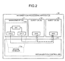
- FIG. 1 is a diagram illustrating an example of the overall configuration of an information processing apparatus according to a first embodiment.
- an information processing apparatus 10 operates a virtualization controller 14, and operates a management operating system (OS) 11, a guest OS (A) 12, and a guest OS (B) 13 as virtual machines (VMs).
- OS management operating system
- A guest OS
- B guest OS
- the number of guest OSs as illustrated in FIG. 1 is an example, and the information processing apparatus 10 can operate any desired number of guest OSs.
- the embodiment is described using an example where the VM is operated with a microkernel hypervisor.
- the management OS 11 is one of the guest OSs for which the virtualization controller 14 executes various controls, and is the VM that has authority different from those of the other guest OSs.
- the management OS 11 provides a virtual bridge device that relays communication between the guest OS (A) 12 and the guest OS (B) 13.
- the management OS 11 has "vif1.0” and "vif2.0” as virtual network interfaces called net-back or the like and has "br0" as a bridge interface connecting "vif1.0" and "vif2.0".
- the guest OS (A) 12 is one of the guest OSs for which the virtualization controller 14 executes various controls, and is the VM having "eth0" as the virtual network interface called net-front or the like. "eth0" is connected to "vif1.0"of the management OS 11.
- the guest OS (B) 13 is one of the guest OSs for which the virtualization controller 14 executes various controls, and is the VM having "eth0" as the virtual network interface called net-front or the like. "eth0" is connected to "vif2.0" of the management OS 11.
- the virtualization controller 14 executes software such as a hypervisor to provide a virtual space in which the VM is operated, and executes various controls, such as generation and deletion of the VM.
- the virtualization controller 14 includes a storage unit 14a, a specifying unit 14b, and a relay unit 14c.
- the storage unit 14a stores therein a storage destination of a computer program for executing relay processing of relaying communication between a guest OS and another guest OS.
- the storage unit 14a stores therein a storage destination of a computer program for operating a virtual bridge device configured by "vif1.0”, “vif2.0", and "br0". Examples of the storage destination include address information.
- the specifying unit 14b specifies the storage destination of the computer program for executing the relay processing from the storage unit 14a when any of the guest OSs operating on the information processing apparatus 10 transmits a packet.
- the relay unit 14c reads out the computer program from the storage destination specified by the specifying unit 14b and executes it, and relays the packet transmitted from the guest OS to a virtual machine as a destination.
- FIG. 2 is a diagram illustrating an example where the virtualization controller 14 operates the virtual bridge device.
- the configurations of the VM and the like that are operated by an information processing apparatus as illustrated in FIG. 2 are the same as those in FIG. 1 .
- An example in which the guest OS (A) 12 transmits a packet to the guest OS (B) 13 is described.
- the guest OS (A) 12 transmits a packet of which destination is set to the IP address of the guest OS (B) 13.
- the net-front "eth0" of the guest OS (A) 12 notifies the net-back "vif1.0" of the management OS 11 of arrival of the packet.
- the management OS 11 reads the packet having arrived at the net-back "vif1.0” and writes the packet into the net-back "vif2.0” through “br0".
- the net-back "vif2.0" notifies the net-front "eth0" of the guest OS (B) 13 of arrival of the packet.
- the guest OS (B) 13 receives the packet transmitted from the guest OS (A) 12 through the virtual bridge of the management OS 11.
- the guest OS (A) 12 transmits a packet of which destination is set to the IP address of the guest OS (B) 13.
- the net-front "eth0" of the guest OS (A) 12 notifies the virtualization controller 14 of arrival of the packet at the net-back "vif1.0" of the management OS 11.
- the virtualization controller 14 specifies a storage destination of a bridge handler 11a from the storage unit 14a.
- the bridge connection between the net-backs "vif1.0" and “vif2.0" through “br0" configures the bridge handler 11a.
- the virtualization controller 14 operates the bridge handler 11a read from the specified storage destination, instead of the management OS 11.
- the virtualization controller 14 notifies the net-front "eth0" of the guest OS (B) 13 that is mapped to the net-back of arrival of the packet. In this manner, the guest OS (B) 13 receives the packet transmitted from the guest OS (A) 12 without the management OS 11 interposed therebetween.
- the virtualization controller 14 of the information processing apparatus 10 operates the bridge handler 11a providing the virtual bridge device, instead of the management OS 11. That is to say, the virtualization controller 14 can read and operate the bridge handler 11a that has operated in the kernel of the management OS 11, using the context of the hypervisor such as the virtualization controller 14. As a result, the information processing apparatus 10 can eliminate communication between the guests OS and the management OS, thereby speeding up the communication between the guests OS.
- FIG. 3 is a functional block diagram illustrating the configuration of the information processing apparatus in the second embodiment.
- an information processing apparatus 20 includes a virtualization region 21 and a controller 30.
- the functional units as illustrated in FIG. 3 are merely examples, and the information processing apparatus 20 may include a storage unit such as a memory, an input/output interface, and a communication interface, for example, as units other than the functional units as illustrated in FIG. 3 .
- the virtualization region 21 is a region that is managed by a hypervisor 31 of the controller 30, and any desired number of VMs can be operated in the virtualization region 21.
- a management OS (A) 22, a management OS (B) 23, a guest OS (A) 24, a guest OS (B) 25, a guest OS (C) 26, and a guest OS (D) 27 are operated as the VMs.
- MAC media access control
- the management OS (A) 22 has a net-back "vif1.0” and a net-back "vif2.0” as virtual network interfaces and "br0" as a bridge interface connecting "vif1.0” and "vif2.0".
- the management OS (B) 23 has a net-back "vif3.0” and a net-back "vif4.0” as the virtual network interfaces and "br1" as a bridge interface connecting "vif3.0" and "vif4.0".
- the guest OS (A) 24 is the VM having a net-front "eth0" as the virtual network interface. "eth0" of the guest OS (A) 24 is connected to "vif1.0" of the management OS (A) 22.
- the guest OS (B) 25 is the VM having a net-front "eth0” as the virtual network interface. "eth0" of the guest OS (B) 25 is connected to "vif2.0" of the management OS (A) 22.
- the guest OS (C) 26 is the VM having a net-front "eth0” as the virtual network interface. "eth0" of the guest OS (C) 26 is connected to "vif3.0" of the management OS (B) 23.
- the guest OS (D) 27 is the VM having a net-front "eth0” as the virtual network interface. "eth0" of the guest OS (D) 27 is connected to "vif4.0" of the management OS (B) 23.
- the management OS (A) 22 provides a virtual bridge device that relays communication between the guest OS (A) 24 and the guest OS (B) 25.
- the management OS (B) 23 provides a virtual bridge device that relays communication between the guest OS (C) 26 and the guest OS (D) 27.
- the hypervisor 31 assigns a virtual processor and a virtual memory to each of the guest OSs and the management OSs operating in the virtualization region 21.
- Each of the guest OSs and the management OSs operates as the VM with the virtual processor and the virtual memory and executes various kinds of processing.
- the virtual memory is achieved by assigning a particular region in a memory of the information processing apparatus 20 as a memory that is used by the guest OSs or the management OSs.
- the virtual processor is achieved by assigning a particular processing capability of a processor of the information processing apparatus 20 as a processor that is used by the guest OSs or the management OSs.
- the controller 30 is a processing unit that includes a processing controller 30a and the hypervisor 31 and controls communication between the guest OSs using these components.
- the controller 30 is an electronic circuit such as a central processing unit (CPU).
- the controller 30 may include an internal memory and the like.
- the processing controller 30a is a processing unit that executes pieces of processing other than those relating to the guest OSs and the management OSs. For example, the processing controller 30a stops activation of an OS that is implemented on the information processing apparatus 20 and stops activation of the hypervisor 31.
- the hypervisor 31 is a processing unit that executes pieces of processing relating to the VMs, such as generation and deletion of the VMs, and controls communication between the guest OS.
- the hypervisor 31 includes an MAC management table 32, a guest ID management table 33, a handler management table 34, an information storage unit 35, a guest specifying unit 36, a handler specifying unit 37, and an operation controller 38.
- the tables are provided in a storage device such as a memory and are updated by a manager or the information storage unit 35 described later.
- the MAC management table 32 stores therein pieces of information for specifying net-backs mapped to the net-fronts of the guest OSs so as to correspond to the MAC addresses of the respective guest OSs.
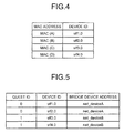
- FIG. 4 is a view illustrating an example of the pieces of information that are stored in the MAC management table 32.
- the MAC management table 32 stores therein "MAC address" and "device ID” in a correspondence manner.
- "MAC address” stored therein indicates the MAC addresses set to the respective guests OS.
- "Device ID” indicates information for specifying the net-backs of the management OSs. For example, the names or identifiers of the net-backs or the device IDs or the like that are used by the net-backs are stored as "device ID”.
- FIG. 4 illustrates an example where the identifiers of the net-backs are stored as "device ID”.
- FIG. 4 indicates the following. That is, the guest OS (A) 24 having the MAC (A) is connected to the net-back "vif1.0" of the management OS (A) 22.
- the guest OS (B) having the MAC (B) is connected to the net-back "vif2.0" of the management OS (A) 22.
- the guest OS (C) 26 having the MAC (C) is connected to the net-back "vif3.0" of the management OS (B) 23.
- the guest OS (D) 27 having the MAC (D) is connected to the net-back "vif4.0" of the management OS (B) 23.
- the guest ID management table 33 stores therein pieces of information relating to the virtual bridge devices that are used by the respective management OSs.
- FIG. 5 is a view illustrating an example of the pieces of information that are stored in the guest ID management table 33. As illustrated in FIG. 5 , the guest ID management table 33 stores therein "guest ID”, "device ID”, and "bridge device address”.
- "Guest ID” stored therein indicates identifiers for identifying the management OSs.
- "Device ID” indicates identifiers for identifying the virtual network interfaces that are used by the management OSs.
- "Bridge device address” indicates pieces of address information indicating the virtual bridge devices themselves that are used by the management OSs, and initial addresses of structures are stored as “Bridge device address”, for example.
- the guest ID management table 33 may store therein a correspondence table of the MAC addresses of the net-fronts and the names of the net-backs. Furthermore, the identifiers of the net-fronts or the like may be used as the device ID.
- FIG. 5 indicates the following. That is, the virtual bridge device having the net-backs "vif1.0” and “vif2.0" of the management OS (A) 22 having the guest ID of "0" is stored at a position of which initial address of the structure is "net_deviceA”. In the same manner, the virtual bridge device having the net-backs "vif3.0” and “vif4.0" of the management OS (B) 23 having the guest ID of "1" is stored at a position of which initial address of the structure is "net_deviceB".
- the handler management table 34 stores therein storage destinations of the bridge handlers that are executed by the respective management OSs. That is to say, the handler management table 34 stores therein entry points of the virtual bridge devices.
- FIG. 6 is a view illustrating an example of pieces of information that are stored in the handler management table 34. As illustrated in FIG. 6 , the handler management table 34 stores therein "guest ID”, "interrupt vector”, "bridge handler”, “structure identifier”, and "guest page table” in a correspondence manner.
- "Guest ID” stored therein indicates identifiers for identifying the management OSs.
- "Interrupt vector” indicates identifiers for identifying interrupt factors.
- “Bridge handler” indicates the initial addresses of storage destinations in which the bridge handlers are stored in a format of a physical address that is used by the management OSs, in other words, in an address format of a virtual address space that is provided by the hypervisor 31.
- "Structure identifier” indicates pieces of information for specifying the types of the structures.
- "Guest page table” indicates page tables that are used for conversion into the virtual space of the management OSs, and indicates the initial addresses of the physical address space that is held by the management OSs, that is, the initial address of the virtual address space that is provided by the hypervisor 31.
- FIG. 6 indicates the following. That is, the bridge handler that is operated by the management OS (A) 22 is stored in a br_netdev_ops0 structure. When an interrupt having the interrupt vector of "0" is generated on the management OS (A) 22 having the guest ID of "0", the physical address "br_netdev_ops0" of the management OS (A) 22 is converted using PT0 into the virtual address. Furthermore, the bridge handler that is operated by the management OS (B) 23 is stored in a br_netdev_ops1 structure. When an interrupt having the interrupt vector of "0" is generated on the management OS (B) 23 having the guest ID of "1”, the physical address "br_netdev_ops1" of the management OS (B) 23 is converted using PT1 into the virtual address.
- the hypervisor 31 can specify the storage destinations of the entire bridge handlers.
- the structure identifiers simple flags or offsets to members of the structures may be stored.
- packet communication between the guest OSs corresponds to the interrupt having the interrupt vector of "0", as an example.
- the information storage unit 35 is a processing unit that stores various kinds of information in the MAC management table 32, the guest ID management table 33, and the handler management table 34.
- the information storage unit 35 may automatically acquire and store setting information and/or address information of the management OS from the memory, the management OS, or the like, and may store information received from the manager or the like.
- the information storage unit 35 stores the MAC address of the guest OS and the net-back of the management OS to which the guest OS is connected in the MAC management table 32 in a correspondence manner. Furthermore, when a management OS is created or the management OS is operated, the information storage unit 35 stores the guest ID, the device ID, and the bridge device address in the guest ID management table 33 in a correspondence manner. In addition, when a management OS is created or the management OS is operated, the information storage unit 35 stores the guest ID, the interrupt vector, the bridge handler, the structure identifier, and the guest page table in the handler management table 34 in a correspondence manner.
- the guest specifying unit 36 is a processing unit that when the guest OS transmits a packet, specifies the address of a bridge device relaying the packet and the management OS operating the bridge device. An example is described below where the guest OS (A) 24 transmits a packet to the guest OS (B) 25.
- the guest specifying unit 36 specifies the MAC address "MAC (A)" of the guest OS (A) 24 as the transmission source and the MAC address "MAC (B)" of the guest OS (B) 25 as the destination from a header and the like of the transmitted packet.
- the guest specifying unit 36 specifies the device ID "vif1.0” corresponding to the specified "MAC (A)” from the MAC management table 32.
- the guest specifying unit 36 specifies the device ID "vif2.0" corresponding to the specified "MAC (B)" from the MAC management table 32.
- the guest specifying unit 36 specifies the guest ID "0" and the bridge address "net_deviceA” corresponding to "vif1.0” from the guest ID management table 33. In the same manner, the guest specifying unit 36 specifies the device ID "0" and the bridge address "net_deviceA” corresponding to "vif2.0" from the guest ID management table 33. In this case, the guest specifying unit 36 determines whether the specified bridge addresses "net_deviceA" are identical. That is to say, the guest specifying unit 36 determines whether the bridge device to which the guest OS as the transmission source is connected and the bridge device to which the guest OS as the destination is connected are identical.
- the guest specifying unit 36 notifies the handler specifying unit 37 of the guest ID and the bridge address specified from the MAC address as the destination and the determination result.
- the guest specifying unit 36 notifies the handler specifying unit 37 of "0" as the interrupt vector indicating that the guest OS (A) 24 has transmitted the packet to the guest OS (B) 25.
- the handler specifying unit 37 is a processing unit that specifies a bridge handler calling a virtual bridge device relaying a transmitted packet. To be specific, the handler specifying unit 37 specifies address information of the storage destination of the bridge handler that executes the packet relay processing in order to deliver the transmitted packet to the destination.
- the handler specifying unit 37 acquires the interrupt vector "0", the guest ID "0", the bridge address "net_deviceA”, and the determination result from the guest specifying unit 36.
- the handler specifying unit 37 refers to the handler management table 34 using the interrupt vector "0", the guest ID "0”, and the bridge address "net_deviceA” as keys to specify the bridge handler "br_netdev_ops0", the structure identifier "BRIDGE", and the guest page table "PTO". Subsequently, the handler specifying unit 37 notifies the operation controller 38 of the pieces of specified information and the bridge address.
- the handler specifying unit 37 may execute the above-mentioned pieces of processing when the determination result from the guest specifying unit 36 is "identical"'.
- the handler specifying unit 37 can notify the management OS of the transmission of the packet from the guest OS, without executing the above-mentioned pieces of processing.
- the operation controller 38 is a processing unit that operates the bridge handler. To be specific, the operation controller 38 reads out the bridge handler that has operated in the kernel of the management OS using the context of the hypervisor 31 and operates it.
- the operation controller 38 acquires the bridge handler "br_netdev_ops0", the structure identifier "BRIDGE", the guest page table "PT0", and the bridge address "net_deviceA” from the handler specifying unit 37.
- the operation controller 38 converts "br_netdev_ops0" from the physical address of the physical address space that is managed by the management OS (A) 22 into a logical address of a logical address space that is managed by the management OS (A) 22, using the guest page table "PT0".
- the operation controller 38 reads out the bridge handler from the converted virtual address using the bridge address "net_deviceA" as an argument, and operates it. In this manner, the operation controller 38 notifies the guest OS (B) 25 as the destination of arrival of the packet at the net-back "eth0" in the operated bridge handler.
- the following describes the procedure of pieces of processing executed by the information processing apparatus 20.
- the initialization processing and the packet relay processing are described.
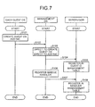
- FIG. 7 is a sequence diagram illustrating the procedure of the initialization processing executed by the information processing apparatus 20 in the second embodiment.
- the management OS executes S103 and S104. That is to say, the management OS outputs a creation direction of the guest OS or an addition direction of the NIC to the hypervisor 31.
- the information storage unit 35 of the hypervisor 31 registers a record storing information corresponding to the created guest OS or the added NIC device in the guest ID management table 33 (S105). In this process, the information storage unit 35 also registers the record storing the information corresponding to the created guest OS or the added NIC device in the MAC management table 32.
- the management OS outputs a registration direction of the bridge handler to the hypervisor 31 (S106 and S107). That is to say, the management OS detects connection between the net-front of the generated guest OS and the net-back of the management OS and establishes a virtual bridge device. The management OS notifies the hypervisor 31 of the storage destination of a computer program for operating the established virtual bridge device.
- the information storage unit 35 of the hypervisor 31 registers the notified storage destination of the computer program from the management OS in the handler management table 34 (S108).
- the information storage unit 35 acquires the guest ID of the management OS, the interrupt vector, the guest page table, and the like from the management OS and the like, and registers them in the handler management table 34 together with the storage destination of the computer program.
- FIG. 8 is a sequence diagram illustrating the procedure of the relay processing executed by the information processing apparatus 20 in the second embodiment.
- the guest OS (A) 24 when a communication request to the guest OS (B) 25 is generated (S201), the guest OS (A) 24 notifies the hypervisor 31 of the generation of the communication request (S202). That is to say, "eth0" as the virtual interface of the guest OS (A) 24 notifies the hypervisor 31 of arrival of a packet at the net-back "vif1.0" of the management OS (A) 22 that is connected with "eth0".
- the guest specifying unit 36 of the hypervisor 31 executes S203 based on the packet having arrived at the net-back "vif1.0". That is to say, the guest specifying unit 36 extracts the MAC address of the guest OS (A) 24 as the transmission source and the MAC address of the guest OS (B) 25 as the destination from the packet. The guest specifying unit 36 specifies the device ID of the net-back that is connected to the guest OS (A) 24 as the transmission source and the device ID of the net-back that is connected to the guest OS (B) 25 as the destination with reference to the MAC management table 32 using the respective MAC addresses as keys.
- the guest specifying unit 36 acquires the guest ID and the bridge device address corresponding to the device ID of the transmission source from the guest ID management table 33 using the device ID of the transmission source as a key (S204). In the same manner, the guest specifying unit 36 acquires the guest ID and the bridge device address corresponding to the device ID of the destination from the guest ID management table 33 using the device ID of the destination as a key (S205).
- the guest specifying unit 36 determines whether the bridge device address specified at S204 and the bridge device address specified at S205 are identical (S206). It is herein assumed that they are identical.
- the handler specifying unit 37 acquires the bridge handler, the structure identifier, and the guest page table from the handler management table 34 using the device ID of the net-back that is connected to the guest OS (B) 25 as the destination as a key (S207).
- the operation controller 38 reads out the bridge handler from the specified bridge handler address using the specified bridge device address as an argument, and operates it (S208 and S209).
- the operation controller 38 notifies the guest OS (B) 25 of arrival of the packet (S210 and S211), the guest OS (B) 25 having the net-front "eth0" mapped to the net-back "vif2.0" that is bridge-connected to the net-back "vif1.0” through “br0".
- the guest OS (B) 25 checks the arrival of the packet, that is, reception of the packet (S212), and notifies the hypervisor 31 of the normal reception (S213).
- the operation controller 38 of the hypervisor 31 notifies the guest OS (A) 24 as the transmission source of a response indicating that the packet has been received by the destination normally (S214 and S215).
- the hypervisor 31 can receive network information set on the management OS, store structure information of the virtual bridge device and the handler thereof to be called, and call the registered handler. This can call the processing of the management OS directly without waiting for operation of the management OS, thereby achieving communication between the guests at high speed.
- the hypervisor can execute the packet relay processing by storing a packet in a queuing buffer of the net-back that is connected to the guest OS as the destination.
- the hypervisor executes a queuing handler storing the packet in the queuing buffer instead of the management OS.
- FIG. 9 is a diagram illustrating an example of the overall configuration of an information processing apparatus 20 in the third embodiment.
- the information processing apparatus 20 in the third embodiment has the same configuration as that of the information processing apparatus in the second embodiment.
- a part of the information processing apparatus 20 in the second embodiment as illustrated in FIG. 3 is extracted and illustrated.
- the information processing apparatus 10 in the third embodiment holds tables that are the same as those in the second embodiment.
- the third embodiment is different from the first embodiment and the second embodiment in that the initial addresses of buffer queues are stored in the guest ID management table 33.
- FIG. 10 is a view illustrating an example of pieces of information that are stored in the guest ID management table 33 in the third embodiment.
- the guest ID management table 33 in the third embodiment stores therein "guest ID”, “device ID”, “bridge device address”, and “buffer queue” in a correspondence manner.
- the "guest ID”, “device ID”, and “bridge device address” stored therein are the same as those in FIG. 5 , and detailed description thereof is omitted.
- "Buffer queue” indicates the initial addresses of buffers storing packets and forming queues.
- the guest ID management table 33 does not always store "bridge device address”.
- FIG. 10 An example described with reference to FIG. 10 indicates the following. That is, the virtual bridge device having the net-backs "vif1.0” and “vif2.0" of the management OS (A) 22 having the guest ID of "0" is stored at a position of which initial address of the structure is "net_deviceA". In addition, the address of the buffer storing a packet that has arrived at the net-back "vif1.0” is "queue1". In the same manner, the virtual bridge device having the net-backs "vif3.0" and “vif4.0" of the management OS (B) 23 having the guest ID of "1" is stored at a position of which initial address of the structure is "net_deviceB". In addition, the address of the buffer storing the packet that has arrived at the net-back "vif3.0" is "queue3".
- the guest OS (A) 24 transmits a packet to the guest OS (B) 25 in this configuration.
- the guest OS (A) 24 transmits a packet of which destination is set to the IP address of the guest OS (B) 25.
- the net-front "eth0" of the guest OS (A) 24 notifies the hypervisor 31 of arrival of the packet at the net-back "vif1.0" of the management OS 22.
- the hypervisor 31 specifies the storage position of a queuing handler 31a of the net-back "vif2.0" that is bridge-connected to the net-back "vif1.0" at which the packet has arrived. That is to say, the hypervisor 31 operates the queuing handler 31a stored in the handler management table 34 using the buffer queue stored in the guest ID management table 33 as an argument, and reads out a queuing buffer. The hypervisor 31 writes the transmitted packet into the read-out queuing buffer of the net-back "vif2.0". The hypervisor 31 notifies the net-front "eth0" of the guest OS (B) 25 mapped to the net-back of arrival of the packet. In this manner, the guest OS (B) 25 receives the packet transmitted from the guest OS (A) 24 by reading the packet from the queuing buffer corresponding to the net-back "vif2.0", without the management OS (A) 22 interposed therebetween.
- the following describes the procedure of pieces of processing executed by the information processing apparatus 20 in the third embodiment.
- the initialization processing and the packet relay processing are described.
- FIG. 11 is a sequence diagram illustrating the procedure of the initialization processing executed by the information processing apparatus 20 in the third embodiment. As illustrated in FIG. 11 , pieces of processing from S301 to S308 are the same as the pieces of processing at S101 to S108 as described above with reference to FIG. 7 , and detailed description thereof is omitted.
- the management OS After executing S301 to S308, the management OS outputs a registration direction of a queuing handler to the hypervisor 31 (S309 and S310). That is to say, the management OS maps the net-back to the net-front of the generated guest OS, and notifies the hypervisor 31 of the address of a computer program calling the buffer corresponding to the net-back.
- the information storage unit 35 of the hypervisor 31 registers the notified storage destination of the computer program calling the queuing handler from the management OS in the handler management table 34 (S311).
- the processing of registering the bridge handler and the processing of registering the queuing handler are not always executed in the order as illustrated in FIG. 11 . For example, they may be executed in parallel, or the processing of registering the queuing handler may be executed before the processing of registering the bridge handler.
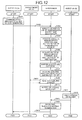
- FIG. 12 is a sequence diagram illustrating the procedure of the relay processing executed by the information processing apparatus 20 in the third embodiment.
- the guest OS (A) 24 when a communication request to the guest OS (B) 25 is generated (S401), the guest OS (A) 24 notifies the hypervisor 31 of the generation of the communication request (S402). That is to say, "eth0" as the virtual interface of the guest OS (A) 24 notifies the hypervisor 31 of arrival of the packet at the net-back "vif1.0" of the management OS (A) 22 that is connected with “eth0".
- the guest specifying unit 36 of the hypervisor 31 executes S403 based on the packet having arrived at the net-back "vif1.0". That is to say, the guest specifying unit 36 extracts the MAC address of the guest OS (A) 24 as the transmission source and the MAC address of the guest OS (B) 25 as the destination from the packet. The guest specifying unit 36 specifies the device ID of the net-back that is connected to the guest OS (A) 24 as the transmission source and the device ID of the net-back that is connected to the guest OS (B) 25 as the destination with reference to the MAC management table 32 using the respective MAC addresses as keys.
- the guest specifying unit 36 acquires the guest ID, the bridge device address, and the buffer queue corresponding to the device ID of the transmission source from the guest ID management table 33 using the device ID of the transmission source as a key (S404). In the same manner, the guest specifying unit 36 acquires the guest ID, the bridge device address, and the buffer queue corresponding to the device ID of the destination from the guest ID management table 33 using the device ID of the destination as a key (S405).
- the guest specifying unit 36 determines whether the buffer queue specified at S304 and the buffer queue specified at S305 are identical (S406). It is herein assumed that they are identical.
- the handler specifying unit 37 acquires the queuing handler, the structure identifier, and the guest page table from the handler management table 34 using the device ID of the net-back that is connected to the guest OS (B) 25 as the destination as a key (S407).
- the operation controller 38 reads out the queuing handler from the specified bridge handler address using the specified buffer queue as an argument, and operates it (S408 and S409). In this manner, the operation controller 38 adds the packet to the buffer specified by operating the queuing handler.
- the operation controller 38 notifies the guest OS (B) 25 of arrival of the packet (S410 and S411), the guest OS (B) 25 having the net-front "eth0" mapped to the net-back "vif2.0" that is bridge-connected to the net-back "vif1.0” through “br0".
- the guest OS (B) 25 checks the arrival of the packet, that is, reception of the packet (S412), and notifies the hypervisor 31 of the normal reception (S413).
- the operation controller 38 of the hypervisor 31 notifies the guest OS (A) 24 as the transmission source of a response indicating that the packet has been received by the destination normally (S414 and S415).
- This configuration enables the hypervisor 31 to register a routine of adding the packet to the queue in the net-back in the handler management table 34 as the queuing handler.
- the hypervisor 31 can execute the processing of storing the packet in the buffer in which the packet to be received by the guest OS as the destination forms the queue, instead of the management OS.
- the hypervisor 31 can reduce an address region or the like to read out instead of the management OS in comparison with operating the entire virtual bridge device instead of the management OS, thereby speeding up the communication between the guest OSs.
- an information processing apparatus to be disclosed can combine the case where the hypervisor operates the bridge handler instead of the management OS and the case where the hypervisor requests the management OS to operate the bridge handler.
- the hypervisor 31 of the disclosed information processing apparatus may request the management OS to relay the packet as in the conventional technique, when the bridge device addresses are not identical at S206 in FIG. 8 . That is to say, the hypervisor 31 of the disclosed information processing apparatus requests the management OS to relay the packet when the net-back that is connected to the guest OS as the transmission source and the net-back that is connected to the guest OS as the destination are not bridge-connected.
- the hypervisor 31 when the transmission source and the destination are not connected to the same bridge, the hypervisor 31 requests the management OS to relay the packet.
- the conventional technique can be used when information that is managed by the hypervisor 31 is increased because the management OS and virtual bridge device are involved.
- the memory capacity and the like that are used by the hypervisor 31 can be reduced, so that communication between the guest OSs is sped up.
- the communication between the guest OSs can be expected to be sped up without incorporating setting information or the like of the bridge devices over the management OSs into the hypervisor 31, and the cost of developing the hypervisor 31 can be reduced.
- the above-mentioned processing can also be applied to S406 in FIG. 12 . In this case, it can also be determined whether the buffer queues are identical, instead of the above-mentioned bridge device addresses.
- An information processing apparatus to be disclosed can also call a registered handler from an interrupt handler when communication with a different processor is made.
- the information processing apparatus 20 holds an interrupt target register that stores therein the guest IDs for identifying a guest OS as an interrupt destination, the MAC addresses of the guest OSs, and identifiers for identifying a processor that operates the guest OS in a correspondence manner.
- the information processing apparatus 20 stores the initial addresses of the interrupt handlers so as to correspond to the guest IDs and the like in the handler management table 34.
- the hypervisor 31 of the information processing apparatus 20 determines whether the guest OS as an interrupt request source and the guest OS as an interrupt request destination operate with the same processor with reference to the interrupt target register when interrupt such as communication between the guest OSs is generated. When it is determined that they operate with the same processor, the hypervisor 31 generates interrupt processing as in the conventional technique. When it is determined that they operate with different processors, the hypervisor 31 reads out a corresponding interrupt handler from the handler management table 34 and operates the interrupt handler instead of an interrupt controller or the like. This can reduce communication between the processors when communication with the different processor is generated, thereby executing the interrupt processing over the processors at high speed.
- All or a part of the pieces of processing that have been described to be executed automatically among the pieces of processing described in the embodiments can be performed manually. All or a part of the pieces of processing that have been described to be executed manually can be performed automatically with a well-known method.
- each device as illustrated in the drawings are functionally conceptual and are not always physically configured as illustrated in the drawings. That is to say, specific modes of separation and integration of the devices are not limited to those in the drawings. In other words, all or a part of them can be separated or integrated functionally or physically based on any desired unit in accordance with various loads, usage conditions, and the like. In addition, all or any part of the processing functions that are executed in the devices may be implemented with a CPU and a computer program to be analyzed and executed on the CPU, or may be achieved as hardware with a wired logic.
- the various pieces of processing as described in the above-mentioned embodiments can be implemented by executing a prepared computer program by a computer system such as a personal computer and a work station.
- a computer system such as a personal computer and a work station.
- the following describes an example of the computer system that executes the computer program having the functions same as those in the above-mentioned embodiments.
- FIG. 13 is a diagram illustrating an example of the hardware configuration of a computer that executes a computer program for virtual machine control.
- a computer 100 includes a central processing unit (CPU) 102, an input device 103, an output device 104, a communication interface 105, a medium reading device 106, a hard disk drive (HDD) 107, and a random access memory (RAM) 108.
- the components as illustrated in FIG. 13 are connected to one another through a bus 101.
- the input device 103 is a mouse or a keyboard
- the output device 104 is a display or the like
- the communication interface 105 is an interface such as an NIC.
- the HDD 107 stores therein a virtual machine control program 107a and pieces of information of the tables as illustrated in FIG. 4 to FIG. 6 .
- various computer programs may be stored in another kind of computer-readable recording medium such as a read only memory (ROM), a random access memory (RAM), and a compact disc read only memory (CD-ROM) to be read by the computer.
- the storage medium may be arranged at a remote location, and the computer may acquire and use the computer programs by accessing the storage medium. In this case, the computer may store the acquired computer programs in its own recording medium for use.
- the CPU 102 reads the virtual machine control program 107a and loads it on the RAM 108 to operate a virtual machine control process 108a for executing the functions as described with reference to FIG. 3 , for example. That is to say, the virtual machine control process 108a executes the same functions as the storage controller 35, the guest specifying unit 36, the handler specifying unit 37, and the operation controller 38 as illustrated in FIG. 3 . Thus, the computer 100 reads out and executes the computer program, thereby operating as the information processing apparatus that executes the method for virtual machine control.
- the computer 100 can also achieve the same functions as those in the above-mentioned embodiments by reading the virtual machine control program 107a from the recording medium by the medium reading device 106 and executing the read virtual machine control program 107a.
- the computer program referred in other embodiments is not limited to be executed by the computer 100.
- the invention can be applied in the same manner to the case where another computer or a server executes the computer program and the case where the computer and the server execute the computer program in corporation.
Landscapes
- Engineering & Computer Science (AREA)
- Software Systems (AREA)
- Theoretical Computer Science (AREA)
- Physics & Mathematics (AREA)
- General Engineering & Computer Science (AREA)
- General Physics & Mathematics (AREA)
- Computer And Data Communications (AREA)
Applications Claiming Priority (1)
| Application Number | Priority Date | Filing Date | Title |
|---|---|---|---|
| PCT/JP2012/052529 WO2013114620A1 (ja) | 2012-02-03 | 2012-02-03 | 仮想マシン制御プログラム、仮想マシン制御方法および情報処理装置 |
Publications (2)
| Publication Number | Publication Date |
|---|---|
| EP2811403A1 true EP2811403A1 (de) | 2014-12-10 |
| EP2811403A4 EP2811403A4 (de) | 2015-10-07 |
Family
ID=48904696
Family Applications (1)
| Application Number | Title | Priority Date | Filing Date |
|---|---|---|---|
| EP12867375.3A Withdrawn EP2811403A4 (de) | 2012-02-03 | 2012-02-03 | Steuerungsprogramm für eine virtuelle maschine, virtuelles maschinensteuerverfahren und informationsverarbeitungsvorrichtung |
Country Status (4)
| Country | Link |
|---|---|
| US (1) | US9268593B2 (de) |
| EP (1) | EP2811403A4 (de) |
| JP (1) | JP5907179B2 (de) |
| WO (1) | WO2013114620A1 (de) |
Families Citing this family (7)
| Publication number | Priority date | Publication date | Assignee | Title |
|---|---|---|---|---|
| US10503442B2 (en) | 2015-01-28 | 2019-12-10 | Avago Technologies International Sales Pte. Limited | Method and apparatus for registering and storing virtual machine unique information capabilities |
| US10437770B2 (en) * | 2015-01-28 | 2019-10-08 | Avago Technologies International Sales Pte. Limited | Method and apparatus for providing virtual machine information to a network interface |
| JP6682897B2 (ja) * | 2016-02-16 | 2020-04-15 | 富士通株式会社 | 通信設定方法、通信設定プログラム、情報処理装置および情報処理システム |
| WO2018179413A1 (ja) | 2017-03-31 | 2018-10-04 | 三菱電機株式会社 | 情報処理装置および情報処理方法 |
| US10445009B2 (en) * | 2017-06-30 | 2019-10-15 | Intel Corporation | Systems and methods of controlling memory footprint |
| US11194606B2 (en) * | 2018-11-28 | 2021-12-07 | Red Hat, Inc. | Managing related devices for virtual machines utilizing shared device data |
| JP7401484B2 (ja) * | 2021-05-28 | 2023-12-19 | Necプラットフォームズ株式会社 | 情報処理装置、情報処理装置の制御方法、及び、情報処理装置の制御プログラム |
Family Cites Families (14)
| Publication number | Priority date | Publication date | Assignee | Title |
|---|---|---|---|---|
| JP2944531B2 (ja) * | 1996-09-12 | 1999-09-06 | 日本電気通信システム株式会社 | Lan間接続装置 |
| US7200666B1 (en) * | 2000-07-07 | 2007-04-03 | International Business Machines Corporation | Live connection enhancement for data source interface |
| US7937701B2 (en) * | 2005-06-30 | 2011-05-03 | Intel Corporation | ACPI communication between virtual machine monitor and policy virtual machine via mailbox |
| JP4799118B2 (ja) | 2005-10-14 | 2011-10-26 | 株式会社ソニー・コンピュータエンタテインメント | 情報処理装置、情報処理システム、通信中継装置および通信制御方法 |
| JP5037016B2 (ja) | 2006-01-17 | 2012-09-26 | 株式会社リコー | ネットワークコンピューティングシステム、通信方法、画像投影装置、画像入出力装置 |
| JP4358224B2 (ja) * | 2006-12-27 | 2009-11-04 | 株式会社東芝 | ゲストosスケジューリング方法及び仮想計算機モニタ |
| US7984449B2 (en) * | 2007-08-15 | 2011-07-19 | International Business Machines Corporation | In-band communication with virtual machines via a hypervisor message bus |
| JP2010066931A (ja) | 2008-09-09 | 2010-03-25 | Fujitsu Ltd | 負荷分散機能を有した情報処理装置 |
| JP5435399B2 (ja) * | 2009-10-07 | 2014-03-05 | 日本電気株式会社 | 省電力化システム、省電力化方法、及び省電力化用プログラム |
| EP2509000A4 (de) * | 2009-12-04 | 2017-09-20 | Nec Corporation | Server und flusssteuerungsprogramm |
| US8739177B2 (en) | 2010-06-21 | 2014-05-27 | Intel Corporation | Method for network interface sharing among multiple virtual machines |
| JP5553221B2 (ja) * | 2010-06-29 | 2014-07-16 | 学校法人近畿大学 | ネットワーク構築演習装置及びその制御方法並びにプログラム及び記録媒体 |
| JP5737050B2 (ja) | 2011-08-15 | 2015-06-17 | 富士通株式会社 | 情報処理装置、割込み制御方法および割込み制御プログラム |
| US9092274B2 (en) * | 2011-12-07 | 2015-07-28 | International Business Machines Corporation | Acceleration for virtual bridged hosts |
-
2012
- 2012-02-03 EP EP12867375.3A patent/EP2811403A4/de not_active Withdrawn
- 2012-02-03 JP JP2013556171A patent/JP5907179B2/ja not_active Expired - Fee Related
- 2012-02-03 WO PCT/JP2012/052529 patent/WO2013114620A1/ja not_active Ceased
-
2014
- 2014-07-30 US US14/446,927 patent/US9268593B2/en not_active Expired - Fee Related
Also Published As
| Publication number | Publication date |
|---|---|
| JP5907179B2 (ja) | 2016-04-26 |
| JPWO2013114620A1 (ja) | 2015-05-11 |
| US20140344811A1 (en) | 2014-11-20 |
| WO2013114620A1 (ja) | 2013-08-08 |
| US9268593B2 (en) | 2016-02-23 |
| EP2811403A4 (de) | 2015-10-07 |
Similar Documents
| Publication | Publication Date | Title |
|---|---|---|
| US9268593B2 (en) | Computer-readable recording medium, virtual machine control method and information processing apparatus | |
| JP5737050B2 (ja) | 情報処理装置、割込み制御方法および割込み制御プログラム | |
| CN104094231B (zh) | 用于支持无限带网络中的虚拟机的动态迁移的系统和方法 | |
| CN107783913B (zh) | 一种应用于计算机的资源访问方法和计算机 | |
| US7533207B2 (en) | Optimized interrupt delivery in a virtualized environment | |
| US7689747B2 (en) | Systems and methods for an augmented interrupt controller and synthetic interrupt sources | |
| US20190146827A1 (en) | Virtualized network function resource management method and device | |
| CN102609298B (zh) | 基于硬件队列扩展的网卡虚拟化系统及其方法 | |
| US20130007743A1 (en) | Method of checking a possibility of executing a virtual machine | |
| WO2017024783A1 (zh) | 一种虚拟化方法、装置和系统 | |
| US11036645B2 (en) | Secure userspace networking for guests | |
| US11544097B2 (en) | Dynamic reconfiguration of virtual devices for migration across device generations | |
| US9612877B1 (en) | High performance computing in a virtualized environment | |
| CN101488113B (zh) | 一种设备驱动域的实现方法、系统及装置 | |
| JP2015002438A (ja) | 通信システム、管理装置、管理方法および管理プログラム | |
| JP2001236237A (ja) | マルチos構成方法 | |
| EP3255544B1 (de) | Unterbrechungssteuergerät | |
| CN114978589B (zh) | 一种轻量级云操作系统及其构建方法 | |
| JP5617761B2 (ja) | 計算機システム、計算機、及び計算機システムの割込み処理方法 | |
| CN114168194A (zh) | 用于控制计算设备的方法、计算设备和计算机存储介质 | |
| JPH0273430A (ja) | 仮想計算機システムにおける入出力動作に伴う事象の通知方法 |
Legal Events
| Date | Code | Title | Description |
|---|---|---|---|
| PUAI | Public reference made under article 153(3) epc to a published international application that has entered the european phase |
Free format text: ORIGINAL CODE: 0009012 |
|
| 17P | Request for examination filed |
Effective date: 20140730 |
|
| AK | Designated contracting states |
Kind code of ref document: A1 Designated state(s): AL AT BE BG CH CY CZ DE DK EE ES FI FR GB GR HR HU IE IS IT LI LT LU LV MC MK MT NL NO PL PT RO RS SE SI SK SM TR |
|
| AX | Request for extension of the european patent |
Extension state: BA ME |
|
| DAX | Request for extension of the european patent (deleted) | ||
| RA4 | Supplementary search report drawn up and despatched (corrected) |
Effective date: 20150902 |
|
| RIC1 | Information provided on ipc code assigned before grant |
Ipc: G06F 9/455 20060101ALI20150828BHEP Ipc: G06F 9/54 20060101AFI20150828BHEP |
|
| STAA | Information on the status of an ep patent application or granted ep patent |
Free format text: STATUS: THE APPLICATION HAS BEEN WITHDRAWN |
|
| 18W | Application withdrawn |
Effective date: 20171219 |