EP2811161B1 - Vakuumpumpe mit beseitigungsfunktion - Google Patents
Vakuumpumpe mit beseitigungsfunktion Download PDFInfo
- Publication number
- EP2811161B1 EP2811161B1 EP14169139.4A EP14169139A EP2811161B1 EP 2811161 B1 EP2811161 B1 EP 2811161B1 EP 14169139 A EP14169139 A EP 14169139A EP 2811161 B1 EP2811161 B1 EP 2811161B1
- Authority
- EP
- European Patent Office
- Prior art keywords
- abatement
- vacuum pump
- exhaust gas
- abatement part
- type
- Prior art date
- Legal status (The legal status is an assumption and is not a legal conclusion. Google has not performed a legal analysis and makes no representation as to the accuracy of the status listed.)
- Active
Links
Images





Classifications
-
- B—PERFORMING OPERATIONS; TRANSPORTING
- B01—PHYSICAL OR CHEMICAL PROCESSES OR APPARATUS IN GENERAL
- B01D—SEPARATION
- B01D53/00—Separation of gases or vapours; Recovering vapours of volatile solvents from gases; Chemical or biological purification of waste gases, e.g. engine exhaust gases, smoke, fumes, flue gases, aerosols
- B01D53/34—Chemical or biological purification of waste gases
- B01D53/46—Removing components of defined structure
- B01D53/68—Halogens or halogen compounds
- B01D53/70—Organic halogen compounds
-
- B—PERFORMING OPERATIONS; TRANSPORTING
- B01—PHYSICAL OR CHEMICAL PROCESSES OR APPARATUS IN GENERAL
- B01D—SEPARATION
- B01D53/00—Separation of gases or vapours; Recovering vapours of volatile solvents from gases; Chemical or biological purification of waste gases, e.g. engine exhaust gases, smoke, fumes, flue gases, aerosols
- B01D53/34—Chemical or biological purification of waste gases
- B01D53/74—General processes for purification of waste gases; Apparatus or devices specially adapted therefor
-
- B—PERFORMING OPERATIONS; TRANSPORTING
- B01—PHYSICAL OR CHEMICAL PROCESSES OR APPARATUS IN GENERAL
- B01D—SEPARATION
- B01D53/00—Separation of gases or vapours; Recovering vapours of volatile solvents from gases; Chemical or biological purification of waste gases, e.g. engine exhaust gases, smoke, fumes, flue gases, aerosols
- B01D53/34—Chemical or biological purification of waste gases
- B01D53/74—General processes for purification of waste gases; Apparatus or devices specially adapted therefor
- B01D53/86—Catalytic processes
- B01D53/8659—Removing halogens or halogen compounds
- B01D53/8662—Organic halogen compounds
-
- B—PERFORMING OPERATIONS; TRANSPORTING
- B01—PHYSICAL OR CHEMICAL PROCESSES OR APPARATUS IN GENERAL
- B01D—SEPARATION
- B01D53/00—Separation of gases or vapours; Recovering vapours of volatile solvents from gases; Chemical or biological purification of waste gases, e.g. engine exhaust gases, smoke, fumes, flue gases, aerosols
- B01D53/34—Chemical or biological purification of waste gases
- B01D53/92—Chemical or biological purification of waste gases of engine exhaust gases
-
- F—MECHANICAL ENGINEERING; LIGHTING; HEATING; WEAPONS; BLASTING
- F04—POSITIVE - DISPLACEMENT MACHINES FOR LIQUIDS; PUMPS FOR LIQUIDS OR ELASTIC FLUIDS
- F04B—POSITIVE-DISPLACEMENT MACHINES FOR LIQUIDS; PUMPS
- F04B37/00—Pumps having pertinent characteristics not provided for in, or of interest apart from, groups F04B25/00 - F04B35/00
- F04B37/06—Pumps having pertinent characteristics not provided for in, or of interest apart from, groups F04B25/00 - F04B35/00 for evacuating by thermal means
-
- F—MECHANICAL ENGINEERING; LIGHTING; HEATING; WEAPONS; BLASTING
- F04—POSITIVE - DISPLACEMENT MACHINES FOR LIQUIDS; PUMPS FOR LIQUIDS OR ELASTIC FLUIDS
- F04B—POSITIVE-DISPLACEMENT MACHINES FOR LIQUIDS; PUMPS
- F04B37/00—Pumps having pertinent characteristics not provided for in, or of interest apart from, groups F04B25/00 - F04B35/00
- F04B37/10—Pumps having pertinent characteristics not provided for in, or of interest apart from, groups F04B25/00 - F04B35/00 for special use
- F04B37/14—Pumps having pertinent characteristics not provided for in, or of interest apart from, groups F04B25/00 - F04B35/00 for special use to obtain high vacuum
-
- B—PERFORMING OPERATIONS; TRANSPORTING
- B01—PHYSICAL OR CHEMICAL PROCESSES OR APPARATUS IN GENERAL
- B01D—SEPARATION
- B01D2251/00—Reactants
- B01D2251/30—Alkali metal compounds
-
- B—PERFORMING OPERATIONS; TRANSPORTING
- B01—PHYSICAL OR CHEMICAL PROCESSES OR APPARATUS IN GENERAL
- B01D—SEPARATION
- B01D2252/00—Absorbents, i.e. solvents and liquid materials for gas absorption
- B01D2252/10—Inorganic absorbents
- B01D2252/103—Water
-
- B—PERFORMING OPERATIONS; TRANSPORTING
- B01—PHYSICAL OR CHEMICAL PROCESSES OR APPARATUS IN GENERAL
- B01D—SEPARATION
- B01D2253/00—Adsorbents used in seperation treatment of gases and vapours
- B01D2253/10—Inorganic adsorbents
- B01D2253/102—Carbon
-
- B—PERFORMING OPERATIONS; TRANSPORTING
- B01—PHYSICAL OR CHEMICAL PROCESSES OR APPARATUS IN GENERAL
- B01D—SEPARATION
- B01D2253/00—Adsorbents used in seperation treatment of gases and vapours
- B01D2253/10—Inorganic adsorbents
- B01D2253/106—Silica or silicates
- B01D2253/108—Zeolites
-
- B—PERFORMING OPERATIONS; TRANSPORTING
- B01—PHYSICAL OR CHEMICAL PROCESSES OR APPARATUS IN GENERAL
- B01D—SEPARATION
- B01D2253/00—Adsorbents used in seperation treatment of gases and vapours
- B01D2253/10—Inorganic adsorbents
- B01D2253/112—Metals or metal compounds not provided for in B01D2253/104 or B01D2253/106
- B01D2253/1124—Metal oxides
-
- B—PERFORMING OPERATIONS; TRANSPORTING
- B01—PHYSICAL OR CHEMICAL PROCESSES OR APPARATUS IN GENERAL
- B01D—SEPARATION
- B01D2253/00—Adsorbents used in seperation treatment of gases and vapours
- B01D2253/20—Organic adsorbents
- B01D2253/206—Ion exchange resins
-
- B—PERFORMING OPERATIONS; TRANSPORTING
- B01—PHYSICAL OR CHEMICAL PROCESSES OR APPARATUS IN GENERAL
- B01D—SEPARATION
- B01D2255/00—Catalysts
- B01D2255/10—Noble metals or compounds thereof
-
- B—PERFORMING OPERATIONS; TRANSPORTING
- B01—PHYSICAL OR CHEMICAL PROCESSES OR APPARATUS IN GENERAL
- B01D—SEPARATION
- B01D2257/00—Components to be removed
- B01D2257/20—Halogens or halogen compounds
- B01D2257/202—Single element halogens
- B01D2257/2025—Chlorine
-
- B—PERFORMING OPERATIONS; TRANSPORTING
- B01—PHYSICAL OR CHEMICAL PROCESSES OR APPARATUS IN GENERAL
- B01D—SEPARATION
- B01D2257/00—Components to be removed
- B01D2257/20—Halogens or halogen compounds
- B01D2257/204—Inorganic halogen compounds
-
- B—PERFORMING OPERATIONS; TRANSPORTING
- B01—PHYSICAL OR CHEMICAL PROCESSES OR APPARATUS IN GENERAL
- B01D—SEPARATION
- B01D2257/00—Components to be removed
- B01D2257/20—Halogens or halogen compounds
- B01D2257/204—Inorganic halogen compounds
- B01D2257/2042—Hydrobromic acid
-
- B—PERFORMING OPERATIONS; TRANSPORTING
- B01—PHYSICAL OR CHEMICAL PROCESSES OR APPARATUS IN GENERAL
- B01D—SEPARATION
- B01D2257/00—Components to be removed
- B01D2257/20—Halogens or halogen compounds
- B01D2257/204—Inorganic halogen compounds
- B01D2257/2045—Hydrochloric acid
-
- B—PERFORMING OPERATIONS; TRANSPORTING
- B01—PHYSICAL OR CHEMICAL PROCESSES OR APPARATUS IN GENERAL
- B01D—SEPARATION
- B01D2257/00—Components to be removed
- B01D2257/55—Compounds of silicon, phosphorus, germanium or arsenic
- B01D2257/553—Compounds comprising hydrogen, e.g. silanes
-
- B—PERFORMING OPERATIONS; TRANSPORTING
- B01—PHYSICAL OR CHEMICAL PROCESSES OR APPARATUS IN GENERAL
- B01D—SEPARATION
- B01D2257/00—Components to be removed
- B01D2257/55—Compounds of silicon, phosphorus, germanium or arsenic
- B01D2257/556—Organic compounds
-
- B—PERFORMING OPERATIONS; TRANSPORTING
- B01—PHYSICAL OR CHEMICAL PROCESSES OR APPARATUS IN GENERAL
- B01D—SEPARATION
- B01D2258/00—Sources of waste gases
- B01D2258/02—Other waste gases
- B01D2258/0216—Other waste gases from CVD treatment or semi-conductor manufacturing
-
- B—PERFORMING OPERATIONS; TRANSPORTING
- B01—PHYSICAL OR CHEMICAL PROCESSES OR APPARATUS IN GENERAL
- B01D—SEPARATION
- B01D2259/00—Type of treatment
- B01D2259/80—Employing electric, magnetic, electromagnetic or wave energy, or particle radiation
- B01D2259/818—Employing electrical discharges or the generation of a plasma
-
- B—PERFORMING OPERATIONS; TRANSPORTING
- B01—PHYSICAL OR CHEMICAL PROCESSES OR APPARATUS IN GENERAL
- B01D—SEPARATION
- B01D53/00—Separation of gases or vapours; Recovering vapours of volatile solvents from gases; Chemical or biological purification of waste gases, e.g. engine exhaust gases, smoke, fumes, flue gases, aerosols
- B01D53/02—Separation of gases or vapours; Recovering vapours of volatile solvents from gases; Chemical or biological purification of waste gases, e.g. engine exhaust gases, smoke, fumes, flue gases, aerosols by adsorption, e.g. preparative gas chromatography
- B01D53/04—Separation of gases or vapours; Recovering vapours of volatile solvents from gases; Chemical or biological purification of waste gases, e.g. engine exhaust gases, smoke, fumes, flue gases, aerosols by adsorption, e.g. preparative gas chromatography with stationary adsorbents
- B01D53/0407—Constructional details of adsorbing systems
- B01D53/0438—Cooling or heating systems
-
- B—PERFORMING OPERATIONS; TRANSPORTING
- B01—PHYSICAL OR CHEMICAL PROCESSES OR APPARATUS IN GENERAL
- B01D—SEPARATION
- B01D53/00—Separation of gases or vapours; Recovering vapours of volatile solvents from gases; Chemical or biological purification of waste gases, e.g. engine exhaust gases, smoke, fumes, flue gases, aerosols
- B01D53/34—Chemical or biological purification of waste gases
- B01D53/46—Removing components of defined structure
- B01D53/68—Halogens or halogen compounds
- B01D53/685—Halogens or halogen compounds by treating the gases with solids
-
- B—PERFORMING OPERATIONS; TRANSPORTING
- B01—PHYSICAL OR CHEMICAL PROCESSES OR APPARATUS IN GENERAL
- B01D—SEPARATION
- B01D53/00—Separation of gases or vapours; Recovering vapours of volatile solvents from gases; Chemical or biological purification of waste gases, e.g. engine exhaust gases, smoke, fumes, flue gases, aerosols
- B01D53/34—Chemical or biological purification of waste gases
- B01D53/74—General processes for purification of waste gases; Apparatus or devices specially adapted therefor
- B01D53/86—Catalytic processes
- B01D53/8659—Removing halogens or halogen compounds
Definitions
- the present invention relates to a vacuum pump for use in an exhaust system of a manufacturing apparatus for manufacturing semiconductor devices, liquid crystal panels, LEDs, or the like, and more particularly to a vacuum pump with abatement function which comprises a vacuum pump, for evacuating a chamber of the manufacturing apparatus, to which an abatement function for treating an exhaust gas discharged from the chamber to make the exhaust gas harmless is added.
- a process gas is introduced into a process chamber which is being evacuated to perform various processes such as an etching process, a CVD process or the like.
- the process chamber for performing various processes such as an etching process, a CVD process or the like is evacuated by a vacuum pump. Further, the process chamber and exhaust apparatuses connected to the process chamber are cleaned periodically by supplying a cleaning gas thereto.
- exhaust gases such as the process gas, the cleaning gas or the like contain a silane-based gas (SiH 4 , TEOS or the like), a halogen-based gas (ClF 3 , HF, F 2 , HCl, Cl 2 or the like), a PFC gas (CF 4 , C 2 F 6 , NF 3 , SF 6 or the like) or the like
- silane-based gas SiH 4 , TEOS or the like
- a halogen-based gas ClF 3 , HF, F 2 , HCl, Cl 2 or the like
- a PFC gas CF 4 , C 2 F 6 , NF 3 , SF 6 or the like
- the exhaust gas treatment apparatus for treating exhaust gases such as various process gases and a cleaning gas has the following problems.
- US 2005 142 010 A1 and EP 1 553 303 A2 both of which rely on the same priority, disclose a conventional vacuum pump system comprising a number of high vacuum pumps, a sub-atmospheric chamber which is connected to the high vacuum pumps by respective exhaust lines and has an abatement device therein, and a backing pump connected to the sub-atmospheric chamber.
- the present invention has been made in view of the above drawbacks. It is therefore an object of the present invention to provide a vacuum pump with abatement function, at a low cost and quickly, which has a small-sized and removable abatement part attached at a downstream side of the vacuum pump, and can meet a required abatement performance by altering the combination of kinds, the number and arrangement, of the attached abatement parts.
- a vacuum pump with abatement function as set forth in claim 1. Further embodiments are inter alia disclosed in the dependent claims.
- the vacuum pump with abatement function comprises: a vacuum pump having a discharge port to which at least one abatement part for treating an exhaust gas discharged from the vacuum pump to make the exhaust gas harmless is attached; wherein the at least one abatement part is selected from a plurality of abatement parts having different treatment types of exhaust gas and/or different treatment amounts of exhaust gas and/or different treatment performances of exhaust gas.
- the present invention even if a gas flow rate or the kind of the gas is changed or a required abatement treatment capacity is changed, by appropriately selecting the kind of the abatement part to be provided at a downstream side of the vacuum pump, it is not necessary to redesign each time, and consequently the exhaust gas treatment can be performed at a low cost.
- the abatement parts having different treatment types of exhaust gas comprise a combustion-type abatement part, a dry-type abatement part, a heater-type abatement part, a wet-type abatement part, a fluorine-fixing-type abatement part, a catalytic-type abatement part, a plasma-type abatement part, a filter-type abatement part, and a dilution-unit-type abatement part.
- optimization of exhaust gas treatment or the required abatement performance can be achieved by preparing abatement parts having different treatment types.
- the at least one abatement part attached to the discharge port of the vacuum pump comprises a plurality of abatement parts which are arranged in series and/or in parallel.
- the exhaust gas treatment in which a plurality of abatement types are combined can be realized by arranging the plurality of abatement parts in series and/or in parallel, and thus the optimization of exhaust gas treatment can be facilitated.
- the plurality of abatement parts are arranged in parallel to have back-up function of the abatement part.
- the back-up function can be provided in a simple way at a low cost, without employing separate back-up systems.
- the plurality of abatement parts arranged in parallel comprise abatement parts having the same treatment type and/or abatement parts having different treatment types.
- the back-up function can be ensured while achieving the optimization of exhaust gas treatment.
- a controller configured to collectively control the vacuum pump and the abatement part is provided in the vacuum pump.
- the abatement part since the abatement part does not have a controller, the abatement part can be small in size, and an interface between the abatement part and the process apparatus is not necessary.
- the abatement part is removably attached to the discharge port of the vacuum pump or an outlet pipe of another abatement part so as to be replaceable.
- the abatement part can be attached and replaced easily, a change of the abatement type or a change of treatment capacity can be made quickly.
- the vacuum pump comprises a single vacuum pump or a plurality of vacuum pumps connected in series and/or in parallel.
- the present invention offers the following advantages.
- FIGS. 1A through 8 A vacuum pump with abatement function according to embodiments of the present invention will be described below with reference to FIGS. 1A through 8 .
- identical or corresponding parts are denoted by identical or corresponding reference numerals throughout views, and will not be described in duplication.
- FIGS. 1A and 1B are views showing a configuration example of a vacuum pump with abatement function according to the present invention.
- FIG.1A is a schematic front view of the vacuum pump with abatement function
- FIG. 1B is a schematic plan view of the vacuum pump with abatement function.
- a vacuum pump with abatement function has a configuration wherein an abatement part 10 is attached to a discharge pipe 1a of a vacuum pump 1.
- the vacuum pump 1 may comprise a single dry vacuum pump or a plurality of dry vacuum pumps connected in series and/or in parallel.
- the single dry vacuum pump or the plural dry vacuum pumps comprise a roots-type dry vacuum pump, a screw-type dry vacuum pump, or the like, which is well known in the art and will not be shown and described in detail below.
- the vacuum pump 1 is illustrated as a vacuum pump having a housing C.
- FIGS. 2A and 2B are views showing another configuration example of a vacuum pump with abatement function according to the present invention.
- FIG.2A is a schematic front view of the vacuum pump with abatement function
- FIG. 2B is a schematic plan view of the vacuum pump with abatement function.
- a vacuum pump with abatement function according to the present invention has a configuration wherein two abatement parts 10, 10 are attached to respective portions branched from a discharge pipe 1a of the vacuum pump 1.
- the discharge pipe 1a which connects a discharge port of the vacuum pump 1 and a gas introduction port of the abatement part 10 has a piping length of not more than 500 mm, specifically 200 mm to 400mm.
- the abatement part 10 of the vacuum pump with abatement function employs a combustion-type, a dry-type, a heater-type, a wet-type, a fluorine-fixing-type, a catalytic-type, a plasma-type, a filter-type, a dilution-unit-type (a blower, N 2 adding, air adding), or the like.
- these plural kinds of the abatement parts 10 employing different treatment types of exhaust gas are prepared.
- a plurality of abatement parts 10 having different treatment amounts of exhaust gas in each of the abatement parts 10 employing different treatment types of exhaust gas are prepared.
- a plurality of abatement parts 10 having different treatment performances of exhaust gas in each of the abatement parts 10 employing different treatment types are prepared.
- an optimal abatement part 10 is selected, depending on the amount and kind of the exhaust gas discharged from the vacuum pump 1, from the plural kinds of abatement parts 10 employing different treatment types, and/or the plural abatement parts 10 having different treatment amounts of exhaust gas, and/or the plural abatement parts 10 having different treatment performances of exhaust gas, and the selected abatement part 10 is integrated with the vacuum pump 1.
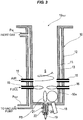
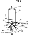
- FIGS. 3 and 4 are views showing a configuration of a combustion-type abatement part 10 as the abatement part of the vacuum pump with abatement function.
- FIG. 3 is a schematic cross-sectional view of the abatement part 10
- FIG. 4 is a schematic perspective view of the abatement part 10.
- the combustion-type abatement part 10 is composed of a cylindrical container as a whole.
- the combustion-type abatement part 10 having a cylindrical container shape is disposed in a vertical direction so that its central axis extends in a vertical direction.
- the combustion-type abatement part 10 comprises a cylindrical member 11 which has a bottom and forms a combustion chamber S therein for forming flames by a burner and combusting an exhaust gas, and an outer cylinder 12 provided so as to surround the cylindrical member 11 with a predetermined distance therebetween.
- a heating chamber 13 for holding and heating an inert gas such as an N 2 gas is formed between the cylindrical member 11 and the outer cylinder 12.
- the inert gas such as an N 2 gas flows into the heating chamber 13 from an inlet port P IN provided at an upper part of the outer cylinder 12 and is heated in the heating chamber 13, and flows out from an outlet port P OUT provided at a lower part of the outer cylinder 12.
- the heating chamber 13 having a double-pipe-structure constitutes a heat exchanger.
- the inert gas heated in the heating chamber 13 can be supplied to the vacuum pump 1.
- the inert gas is heated in the heating chamber 13 to a temperature which is substantially equal to an internal temperature of the vacuum pump 1, for example, to a temperature of 190°C to 220°C.
- a gas introduction port 10 IN for introducing the exhaust gas to be treated into the combustion chamber is formed at a lower part of a circumferential wall of the combustion-type abatement part 10.
- a gas outlet 10 OUT for discharging the gas after treatment is formed at the upper end of the abatement part 10.
- a plurality of air nozzles 15 for supplying air into the combustion chamber S and a plurality of fuel nozzles 16 for supplying a fuel into the combustion chamber S are provided in the abatement part 10. As shown in FIGS.
- the air nozzles 15 extend at a predetermined angle to the tangential direction of the abatement part 10 to blow off air so as to form swirling flows along an inner circumferential surface of the circumferential wall of the cylindrical member 11.
- the fuel nozzles 16 extend at a predetermined angle to the tangential direction of the cylindrical member 11 to blow off the fuel so as to form swirling flows along the inner circumferential surface of the circumferential wall of the cylindrical member 11.
- the air nozzles 15 and the fuel nozzles 16 are disposed respectively at predetermined intervals in the circumferential direction of the abatement part 10.
- a UV sensor 18 for detecting flames and a plug 19 for ignition are provided on the bottom of the cylindrical member 11.
- a cylindrical pilot burner part 20 is provided so as to surround the plug 19.
- a fuel supply port 21 for supplying a fuel for forming a flame and an air supply port 22 for supplying air are formed in the pilot burner part 20.
- a pilot burner flame PB is formed by igniting the fuel supplied from the fuel supply port 21 with the plug 19.
- the fuel is blown off from the plural fuel nozzles 16 provided in the abatement part 10 toward the combustion chamber S so as to form the swirling flows. Further, air is blown off from the plural air nozzles 15 toward the combustion chamber S so as to form the swirling flows. Then, the mixture gas of fuel and air is ignited by the pilot burner PB, and thus the swirling flows of flames (swirling flames) are formed along the inner circumferential surface of the cylindrical member 11.
- the exhaust gas to be treated is blown off toward the combustion chamber S from the exhaust gas introduction port 10 IN which opens on the inner circumferential surface of the cylindrical member 11.
- the blown-off exhaust gas mixes with the swirling flames of the mixture gas and is combusted.
- combustion efficiency of the exhaust gas becomes high.
- the air ejected from the air nozzles 15 is also swirling, while the air flows mix with the flames to accelerate the swirling flows of the flames, the exhaust gas is oxidatively decomposed.
- the treated gas is discharged from the gas outlet 10 OUT at the upper end of the abatement part 10, and is then discharged to an exhaust duct.
- the exhaust gas discharged from the vacuum pump 1 has been heated by compression heat in the vacuum pump 1 to a temperature of about 200°C, and the heated exhaust gas is introduced from the discharge pipe 1a directly into the abatement part 10 wherein the exhaust gas can be treated to be made harmless by combustion. Therefore, it is not necessary to heat the exhaust gas from normal temperature, and an amount of fuel used in the abatement part 10 can be reduced, thus achieving energy saving. Since the exhaust gas heated to a temperature of about 200°C flows through the discharge pipe 1a of the vacuum pump 1, it is not necessary to heat the discharge pipe 1a by a heater for piping. Therefore, it is not necessary to install the heater for piping, and thus energy saving can be achieved. Further, since the discharge pipe 1a which connects the vacuum pump 1 and the abatement part 10 has a piping length of not more than 500 mm, the product can be prevented from being attached to the discharge pipe 1a.
- combustion waste heat generated by abatement treatment of the exhaust gas is utilized to heat the inert gas such as an N 2 in the heating chamber 13 of the abatement part 10, and the heated inert gas is supplied to the vacuum pump 1. Therefore, purging of the vacuum pump 1 can be performed by the heated inert gas, and thus a product can be prevented from being attached to the interior of the vacuum pump 1. According to the present invention, it is not necessary to install a dedicated heater for heating the inert gas, thus achieving energy saving.
- the inert gas may be a gas which does not react with the contained gases, other than N 2 .
- the inert gas may be a noble gas such as He, Ar or Kr, or CO 2 .
- FIG. 5 is a schematic cross-sectional view showing a configuration of a wet-type abatement part 10 as the abatement part of the vacuum pump with abatement function.
- the wet-type abatement part 10 comprises a treatment chamber body 30 having a cylindrical container shape as a whole.
- a treatment chamber 31 is formed in the treatment chamber body 30.
- a gas introduction port 10 IN for introducing the exhaust gas to be treated into the treatment chamber is formed at a lower part of a circumferential wall of the treatment chamber body 30.
- a gas outlet 10 OUT for discharging the gas after treatment is formed at the upper end of the treatment chamber body 30.
- a water spray nozzle 32 for supplying water into the treatment chamber 31 is provided at an upper part of the treatment chamber 31.
- Fillers 34 for enhancing a contact efficiency between the water sprayed from the water spray nozzle 32 and the exhaust gas are provided below the spray nozzle 32.
- a discharge outlet 33 for discharging drainage water in which the exhaust gas is dissolved is provided at a bottom wall portion of the treatment chamber 31.
- the exhaust gas is introduced into the treatment chamber 31 from the gas introduction port 10 IN .
- the water spray nozzle 32 sprays water, and the sprayed water passes through the fillers 34 and is then discharged from the discharge outlet 33.
- the exhaust gas introduced from the gas introduction port 10 IN is brought into contact with the water which has fallen from the fillers 34, and thus water-soluble components in the exhaust gas dissolve in the water.
- the exhaust gas passes through the fillers 34 whose gas-liquid interface area is increased to improve the contact efficiency between the exhaust gas and the water, thereby dissolving water-soluble components which have not dissolved yet.
- the remaining components in the exhaust gas which still have not dissolved in the water are cleaned by the water sprayed from the water spray nozzle 32 disposed above the fillers 34.
- the treated gas is discharged from the gas outlet 10 OUT .
- the fillers comprise raschig rings.
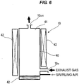
- FIG. 6 is a schematic cross-sectional view showing a configuration of a heater-type abatement part 10 as the abatement part of the vacuum pump with abatement function.
- the heater-type abatement part 10 comprises a treatment chamber body 40 having a cylindrical container shape as a whole.
- a treatment chamber 41 is formed in the treatment chamber body 40.
- Heaters 42 are provided around a circumferential wall and at the outer bottom portion, of the treatment chamber body 40.
- a gas introduction port 10 IN for introducing the exhaust gas to be treated into the treatment chamber is formed at a lower part of the circumferential wall of the treatment chamber body 40, and a gas outlet 10 OUT for discharging the gas after treatment is formed at the upper end of the treatment chamber body 40.
- Swirling air is supplied from a lower part of the circumferential wall of the treatment chamber body 40.
- the exhaust gas is introduced into the treatment chamber 41 from the gas introduction port 10 IN .
- the exhaust gas introduced into the treatment chamber 41 is decomposed at a high temperature of approximately 500°C to 1400°C while being swirled by the swirling air.
- the treated gas is discharged from the gas outlet 10 OUT .
- FIG. 7 is a schematic cross-sectional view showing a configuration of a dry-type abatement part 10 as the abatement part of the vacuum pump with abatement function.
- the dry-type abatement part 10 comprises a treatment chamber body 50 having a cylindrical container shape as a whole.
- a treatment chamber 51 is formed in the treatment chamber body 50.
- a gas introduction port 10 IN for introducing the exhaust gas to be treated into the treatment chamber is formed at a lower part of a circumferential wall of the treatment chamber body 50, and a gas outlet 10 OUT for discharging the gas after treatment is formed at the upper end of the abatement portion 10.
- the treatment chamber 51 is filled with treatment agent (chemical agent) 52 to adsorb the exhaust gas.
- the treatment agent comprises metal oxides, zeolites, ion-exchange resins, alkaline agents, noble metal catalysts, activated carbons, or the like.
- a heater may be provided at an outer circumference of the treatment chamber 51 to heat the treatment agent (chemical agent).
- FIG. 8 is a schematic cross-sectional view showing a configuration of a fluorine-fixing-type abatement part 10 as the abatement part of the vacuum pump with abatement function.
- the fluorine-fixing-type abatement part 10 comprises a treatment chamber body 60 having a cylindrical container shape as a whole.
- a treatment chamber 61 is formed in the treatment chamber body 60.
- the fluorine-fixing-type abatement part 10 has heaters 62 around a circumferential wall and at the outer bottom portion, of the treatment chamber 61.
- a gas introduction port 10 IN for introducing the exhaust gas to be treated into the treatment chamber is formed at a lower part of the circumferential wall of the treatment chamber body 60, and a gas outlet 10 OUT for discharging the gas after treatment is formed at the upper end of the treatment chamber body 60.
- the treatment chamber 61 is filled with fixing chemical agent 63 to fix F (fluorine) components.
- a mixed agent which comprises metal components having high decomposition ability of the exhaust gas and metal components for fixing the decomposed F (fluorine) components, is used as the fixing chemical agent.
- PFC gases CF 4 , C 2 F 6 , NF 3 , SF 6 or the like
- F (fluorine) components contained in by-product gas such as SiF 4
- the abatement part is provided at a downstream side of each vacuum pump, in accordance with a gas flow rate discharged from the vacuum pump and the kinds of process gases, thereby integrating the vacuum pump and the abatement part.
- a dry-type abatement part filled with metal oxides should be used.
- a wet-type abatement part for removing powder such as a fan scrubber, may be provided at a downstream side of the combustion-type abatement part.
- the gas treatment performance of the abatement part is lowered.
- the gas treatment performance can be tailored simply by increasing the number of the dry-type abatement parts when using the dry-type abatement parts, or by increasing the number of the combustion-type abatement parts or by replacing the existing abatement part (parts) with a fuel-rich abatement part (parts) when using the combustion-type.
- the fuel-rich abatement part is a combustion-type abatement part in which a flow rate of fuel to be used for combustion is increased; it includes a combustion-type abatement part in which diameters of piping are enlarged to increase the flow rates of utilities such as a fuel and air, a combustion-type abatement part in which the number of nozzles is increased, and a combustion-type abatement part having a flow rate regulating mechanism for a high flow rate. Further, a lowering of the gas treatment performance of the abatement part caused by an increase of the gas flow rate can be prevented by using an abatement part employing a different kind of fuel.
- the abatement part is small in size and easily removable as a unit of a vacuum pump, setting up and relocation of the abatement part can be carried out at a low cost and in a short period of time.
- the abatement part Since the abatement part is not installed fixedly on a base or a floor, when being in need of replacement, the abatement part can be easily replaced by means of clamp coupling or the like. Further, when the abatement part breaks down, the abatement part can be replaced with a normal product without being repaired on site. Accordingly, the shutdown time of the process apparatus can be shortened. Furthermore, when the abatement part breaks down, the abatement part can be brought back to the factory to be repaired, and thus on-site workload is lessened, and advanced repair, which is difficult to perform on site, can be performed.
- a plurality of abatement parts which are arranged in series, in parallel, or combination thereof, are provided at a downstream side of the vacuum pump.
- the kinds of the abatement part include a combustion-type, a dry-type, a heater-type, a wet-type, a fluorine-fixing-type, a catalytic-type, a plasma-type, a filter-type, and a dilution-unit-type (a blower, N 2 adding, air adding).
- the respective abatement apparatuses have been designed such that fuel flow rates have been different depending on the gas flow rates to be introduced. Further, an expensive mass flow controller (MFC) has been used so as to be able to change the amount of the fuel even in a single abatement apparatus.
- MFC mass flow controller
- a plurality of abatement parts which have different fuel flow rates are prepared, and the plural abatement parts are combined in series or in parallel in accordance with the gas flow rate to be introduced into the abatement parts.
- the optimal exhaust gas treatment can be realized at a low cost. Further, it is not necessary to use the expensive mass flow controller (MFC) or the like.
- heat generated by the combustion-type abatement part can be reutilized, for example, to heat an N 2 gas for the vacuum pump.
- filler compositions of chemical agents for the dry-type columns have been changed depending on respective processes. Therefore, in order to achieve the optimization of exhaust gas treatment, a large variety of dry-type columns have needed to be prepared. In addition, the changes of filler compositions have needed to bring back the dry-type columns to the factory each time, and to replace the chemical agents therein.
- the preceding and/or subsequent abatement parts of the plural abatement parts can be easily replaced with an abatement part (parts) filled with other kind (kinds) of chemical agent, and thus the optimization of exhaust gas treatment to exhaust gases generated from different processes can be achieved.
- compositions of the chemical agent can be changed quickly.
- a noble gas may be purified and recycled.
- Pd catalyst is used for H 2 treatment to generate heat, which can be reused, for example, to heat N 2 gas for the vacuum pump.
- abatement apparatuses having different heater capacities with respect to respective gas flow rates to be introduced have needed to be prepared.
- the abatement part since plural kinds of heater-type abatement parts having respectively different heater capacities are prepared and arranged depending on a gas flow rate to be introduced, in series, in parallel or in combination thereof, the abatement part does not need to be designed to have excessive heater capacity, but the optimal abatement part which fits with the gas flow rate to be introduced can be provided at a low cost.
- the catalytic-type abatement part or the fluorine-fixing-type abatement part at a downstream side of the heater-type abatement part, treatment of PFC gases (CF 4 , C 2 F 6 , NF 3 , SF 6 or the like) and fluorine-fixing can be performed. Furthermore, heat generated in the heater-type abatement part can be reused, for example, to heat N 2 gas for the vacuum pump.
- PFC gases CF 4 , C 2 F 6 , NF 3 , SF 6 or the like
- the present invention by providing the minimum necessary combination of the abatement parts for each of the required treatment performances, specifications having excessive performances can be avoided, and thus the exhaust gas can be treated at a low initial cost and also at a low running cost.
- the combustion-type abatement apparatus or the heater-type abatement apparatus incorporates a water-scrubber for treating acidic gases and powder.
- a water-scrubber for treating acidic gases and powder.
- the water-scrubber is incorporated as a package of the apparatus, it has been difficult to design only the water-scrubber each time to increase or decrease the treatment performance depending on the required treatment performance.
- the required gas treatment can be realized by installing a wet-type abatement part which fits the required treatment performance at a downstream side of the combustion-type abatement part or the heater-type abatement part, without the need for designing each time.
- CF 4 cannot be treated by the heater-type abatement part.
- CF 4 can be treated by adding the fluorine-fixing-type abatement part at the downstream side of the heater-type abatement part.
- CF 4 can be treated by replacing the heater-type abatement part with the combustion-type abatement part.
- the acid gases can be treated by adding the wet-type abatement part at the downstream side of the combustion-type abatement part.
- the combustion-type abatement part is demanded to improve the treatment performance of by-product powder, the powder can be treated by adding the wet-type abatement part or filter-type abatement part for removing the powder at the downstream side of the combustion-type abatement part.
- the abatement part is small in size and inexpensive, if required to be replaced with another type of abatement part, only the replacement of the existing abatement part with another type of abatement part is sufficient.
- the design modification of the complex abatement apparatus and the replacement of the large and expensive abatement apparatus are not required, and thus the abatement type can be changed easily.
- a plurality of abatement parts are provided in parallel at an immediately downstream side of the vacuum pump, thereby providing back-up function of the abatement part.
- the back-up function can be provided in a simple way at a low cost.
- the back-up function may be provided by connecting the same type of abatement parts in parallel, or by connecting the different types of abatement parts in parallel.
- a dry-type abatement part can be easily placed for the back-up of the combustion-type abatement part.
- the abatement part does not require to be installed fixedly on the base or the floor, it can be easily replaced with a normal product. If replacement of the abatement part is needed, a line is bypassed to the back-up abatement part, and the abatement part to be replaced is removed by means of the clamp coupling or the like. Thus, the abatement part can be replaced without shutdown of the process operation. In this manner, an interruption of the process operation for the maintenance of the abatement part can be avoided.
- An overhaul of an exhaust system including the abatement part can be performed concurrently with an overhaul of the vacuum pump, thus shortening shutdown time of the process.
- the control of the respective abatement parts is performed by a controller of the vacuum pump.
- the control of the abatement parts is incorporated in the controller of the vacuum pump to allow the abatement parts not to have a controller.
- a dedicated controller for controlling the plural abatement parts is provided.
- two or more abatement parts are selected from the plural abatement parts, and are then combined into one package.
- the combination of the combustion-type abatement part and the wet-type abatement part, the combination of the heater-type abatement part and the wet-type abatement part, and the combination of the wet-type abatement part, the heater-column-type abatement part and the wet-type abatement part are packaged, respectively.
- the packaged combination of the abatement parts can serve as an apparatus which corresponds to the combustion-type exhaust treatment apparatus, the thermo-oxidative-decomposition-type exhaust treatment apparatus, or the catalytic-type exhaust treatment apparatus, which has been installed fixedly on a base or a floor, and also as a product to meet the treatment capacity of the required specification.
Landscapes
- Engineering & Computer Science (AREA)
- Chemical & Material Sciences (AREA)
- Environmental & Geological Engineering (AREA)
- Chemical Kinetics & Catalysis (AREA)
- Health & Medical Sciences (AREA)
- Biomedical Technology (AREA)
- Analytical Chemistry (AREA)
- General Chemical & Material Sciences (AREA)
- Oil, Petroleum & Natural Gas (AREA)
- Mechanical Engineering (AREA)
- General Engineering & Computer Science (AREA)
- Combustion & Propulsion (AREA)
- Treating Waste Gases (AREA)
- Incineration Of Waste (AREA)
- Drying Of Semiconductors (AREA)
- Compressor (AREA)
- Compressors, Vaccum Pumps And Other Relevant Systems (AREA)
- Exhaust Gas Treatment By Means Of Catalyst (AREA)
Claims (7)
- Ein System mit einer Vakuumpumpe und wenigstens einem Abgasbehandlungsteil, wobei Folgendes vorgesehen ist:eine Vakuumpumpe (1) mit einem Auslassanschluss, an dem mindestens ein Abgasbehandlungsteil (10) angebracht ist zur Behandlung eines Abgases abgegeben von der Vakuumpumpe (1), um das Abgas harmlos zu machen;wobei das Abgasbehandlungsteil (10) einen zylindrischen Behälter aufweist, angebracht an dem Auslassanschluss der Vakuumpumpe (1) und konfiguriert zur Behandlung des darin befindlichen Abgases;wobei das mindestens eine Abgasbehandlungsteil ausgewählt ist aus einer Vielzahl von Abgasbehandlungsteilen mit unterschiedlichen Behandlungstypen für das Abgas und/oder unterschiedlichen Behandlungsmengen des Abgases und/oder unterschiedlichen Abgasbehandlungsleistungen des Abgases; unddadurch gekennzeichnet, dass der zylindrische Behälter des mindestens einen Abgasbehandlungsteils (10) ein zylindrisches Glied (11) aufweist, welches eine Verbrennungskammer (S) darinnen bildet zur Verbrennung des Abgases, einen Außenzylinder (12), vorgesehen, um das Zylinderglied (11) zu umgeben, und eine Heizkammer (13) gebildet zwischen dem Zylinderglied (11) und dem Außenzylinder (12) und konfiguriert zum Halten und Erhitzen eines inerten Gases, wodurch Wärme, erzeugt durch die Verbrennung des Abgases in der Verbrennungskammer (S), verwendet wird, um das inerte Gas gehalten in der Heizkammer (13) zu erwärmen, wobei das erhitzte inerte Gas an die Vakuumpumpe (1) geliefert wird.
- Das System nach Anspruch 1, wobei der mindestens eine Abgasbehandlungsteil (10) angebracht an dem Auslassanschluss der Vakuumpumpe (1) eine Vielzahl von Abgasbehandlungsteilen aufweist, die in Reihe und/oder parallel angeordnet sind.
- Das System nach Anspruch 2, wobei die Vielzahl der Abgasbehandlungsteile (10) parallel angeordnet sind, um eine Backup-Funktion des Abgasbehandlungsteils vorzusehen.
- Das System nach Anspruch 3, wobei die Vielzahl der Abgasbehandlungsteile (10), die parallel angeordnet sind, Abgasbehandlungsteile aufweist, mit dem gleichen Behandlungstyp und/oder wobei die Abgasbehandlungsteile unterschiedliche Behandlungstypen aufweisen.
- Das System nach einem der Ansprüche 1 bis 4, wobei eine Steuervorrichtung konfiguriert ist, um kollektiv die Vakuumpumpe (1) und das Abgasbehandlungsteil (10) zu steuern, die in der Vakuumpumpe (1) vorgesehen ist.
- Das System nach einem der Ansprüche 1 bis 4, wobei das Abgasbehandlungsteil (10) entfernbar an dem Auslassanschluss der Vakuumpumpe (1) befestigt ist, oder an einem Auslassrohr eines anderen Abgasbehandlungsteils, um so ersetzbar zu sein.
- Das System nach einem der Ansprüche 1 bis 4, wobei die Vakuumpumpe (1) eine einzige Vakuumpumpe oder eine Vielzahl von Vakuumpumpen verbunden in Reihe und/oder parallel aufweist.
Applications Claiming Priority (1)
| Application Number | Priority Date | Filing Date | Title |
|---|---|---|---|
| JP2013109907A JP6368458B2 (ja) | 2013-05-24 | 2013-05-24 | 除害機能付真空ポンプ |
Publications (2)
| Publication Number | Publication Date |
|---|---|
| EP2811161A1 EP2811161A1 (de) | 2014-12-10 |
| EP2811161B1 true EP2811161B1 (de) | 2019-08-14 |
Family
ID=50732068
Family Applications (1)
| Application Number | Title | Priority Date | Filing Date |
|---|---|---|---|
| EP14169139.4A Active EP2811161B1 (de) | 2013-05-24 | 2014-05-20 | Vakuumpumpe mit beseitigungsfunktion |
Country Status (6)
| Country | Link |
|---|---|
| US (1) | US10143964B2 (de) |
| EP (1) | EP2811161B1 (de) |
| JP (1) | JP6368458B2 (de) |
| KR (1) | KR20140138044A (de) |
| CN (1) | CN104179688A (de) |
| TW (1) | TWI648090B (de) |
Families Citing this family (9)
| Publication number | Priority date | Publication date | Assignee | Title |
|---|---|---|---|---|
| JP6166102B2 (ja) | 2013-05-30 | 2017-07-19 | 株式会社荏原製作所 | 除害機能付真空ポンプ |
| JP5977419B1 (ja) * | 2015-03-12 | 2016-08-24 | 株式会社荏原製作所 | 排ガス処理装置 |
| US11295935B2 (en) * | 2015-05-11 | 2022-04-05 | Ebara Corporation | Electromagnet device, electromagnet controller, electromagnet control method, and electromagnet system |
| GB2561899B (en) | 2017-04-28 | 2020-11-04 | Edwards Ltd | Vacuum pumping system |
| JP7020951B2 (ja) | 2018-02-09 | 2022-02-16 | 東京エレクトロン株式会社 | プラズマ処理システムおよびプラズマ処理方法 |
| CN111837215B (zh) * | 2018-03-26 | 2024-03-22 | 株式会社国际电气 | 处理装置、半导体器件的制造方法以及记录介质 |
| GB2579197B (en) * | 2018-11-22 | 2021-06-09 | Edwards Ltd | Abatement method |
| FR3112086B1 (fr) * | 2020-07-09 | 2022-07-08 | Pfeiffer Vacuum | Dispositif de traitement des gaz et ligne de vide |
| CN115522177B (zh) * | 2021-07-23 | 2023-05-09 | 上海汉钟精机股份有限公司 | 用于太阳能电池片的镀膜工艺的智能排粉控制方法 |
Citations (1)
| Publication number | Priority date | Publication date | Assignee | Title |
|---|---|---|---|---|
| EP2815800A2 (de) * | 2013-05-30 | 2014-12-24 | Ebara Corporation | Vakuumpumpe mit Funktion zur Schadstoffreduktion |
Family Cites Families (19)
| Publication number | Priority date | Publication date | Assignee | Title |
|---|---|---|---|---|
| JPS6453075A (en) * | 1987-08-24 | 1989-03-01 | Hitachi Ltd | Vacuum exhaust device |
| IL117775A (en) | 1995-04-25 | 1998-10-30 | Ebara Germany Gmbh | Inhalation system with gas exhaust cleaner and operating process for it |
| JP3246708B2 (ja) * | 1995-05-02 | 2002-01-15 | 東京エレクトロン株式会社 | トラップ装置及びこれを用いた未反応処理ガス排気機構 |
| US6383300B1 (en) * | 1998-11-27 | 2002-05-07 | Tokyo Electron Ltd. | Heat treatment apparatus and cleaning method of the same |
| JP4294910B2 (ja) * | 2002-03-27 | 2009-07-15 | 株式会社東芝 | 半導体デバイス製造プラントにおける物質供給システム |
| US7105037B2 (en) * | 2002-10-31 | 2006-09-12 | Advanced Technology Materials, Inc. | Semiconductor manufacturing facility utilizing exhaust recirculation |
| JP2004200364A (ja) * | 2002-12-18 | 2004-07-15 | Seiko Epson Corp | 排ガス処理装置および排ガス処理方法 |
| US7569193B2 (en) * | 2003-12-19 | 2009-08-04 | Applied Materials, Inc. | Apparatus and method for controlled combustion of gaseous pollutants |
| US7021903B2 (en) * | 2003-12-31 | 2006-04-04 | The Boc Group, Inc. | Fore-line preconditioning for vacuum pumps |
| US7278831B2 (en) * | 2003-12-31 | 2007-10-09 | The Boc Group, Inc. | Apparatus and method for control, pumping and abatement for vacuum process chambers |
| WO2005072852A1 (ja) * | 2004-01-29 | 2005-08-11 | Taiyo Nippon Sanso Corporation | 排ガス処理方法および排ガス処理装置 |
| GB0412623D0 (en) * | 2004-06-07 | 2004-07-07 | Boc Group Plc | Method controlling operation of a semiconductor processing system |
| US7368000B2 (en) * | 2004-12-22 | 2008-05-06 | The Boc Group Plc | Treatment of effluent gases |
| US20060210405A1 (en) * | 2005-03-16 | 2006-09-21 | Fuksa Richard C | Vacuum pressure controller |
| GB0521944D0 (en) * | 2005-10-27 | 2005-12-07 | Boc Group Plc | Method of treating gas |
| WO2008147522A1 (en) * | 2007-05-25 | 2008-12-04 | Applied Materials, Inc. | Methods and apparatus for assembling and operating electronic device manufacturing systems |
| EP2315972A1 (de) * | 2008-07-31 | 2011-05-04 | Michele Cataldo | Verbrennungsanlage mit schadstoffminderung |
| GB0902234D0 (en) * | 2009-02-11 | 2009-03-25 | Edwards Ltd | Method of treating an exhaust gas stream |
| KR101435371B1 (ko) * | 2012-10-16 | 2014-08-29 | 주식회사 글로벌스탠다드테크놀로지 | CO, NOx 개별 제어 방식을 이용한 저공해 연소방법 |
-
2013
- 2013-05-24 JP JP2013109907A patent/JP6368458B2/ja active Active
-
2014
- 2014-05-20 EP EP14169139.4A patent/EP2811161B1/de active Active
- 2014-05-20 KR KR20140060265A patent/KR20140138044A/ko not_active Withdrawn
- 2014-05-21 CN CN201410217789.6A patent/CN104179688A/zh active Pending
- 2014-05-21 TW TW103117741A patent/TWI648090B/zh active
- 2014-05-21 US US14/284,305 patent/US10143964B2/en active Active
Patent Citations (1)
| Publication number | Priority date | Publication date | Assignee | Title |
|---|---|---|---|---|
| EP2815800A2 (de) * | 2013-05-30 | 2014-12-24 | Ebara Corporation | Vakuumpumpe mit Funktion zur Schadstoffreduktion |
Also Published As
| Publication number | Publication date |
|---|---|
| KR20140138044A (ko) | 2014-12-03 |
| CN104179688A (zh) | 2014-12-03 |
| JP2014227968A (ja) | 2014-12-08 |
| JP6368458B2 (ja) | 2018-08-01 |
| TWI648090B (zh) | 2019-01-21 |
| EP2811161A1 (de) | 2014-12-10 |
| US20140348717A1 (en) | 2014-11-27 |
| US10143964B2 (en) | 2018-12-04 |
| TW201509510A (zh) | 2015-03-16 |
Similar Documents
| Publication | Publication Date | Title |
|---|---|---|
| EP2811161B1 (de) | Vakuumpumpe mit beseitigungsfunktion | |
| US10632419B2 (en) | Vacuum pump with abatement function | |
| EP2784321B1 (de) | Vakuumpumpe mit Senkungsfunktion | |
| EP2808421B1 (de) | Vakuumpumpe mit Beseitungsfunktion | |
| US20130171919A1 (en) | Exhaust system | |
| KR101175003B1 (ko) | 인덕션 코일을 이용한 유독성 폐가스 처리장치 | |
| KR100711941B1 (ko) | 폐가스 정화처리 장치 | |
| KR200405303Y1 (ko) | 폐가스 정화처리 장치 | |
| JPWO2008096466A1 (ja) | ガス処理装置及び該装置を用いたガス処理システムとガス処理方法 | |
| KR101115594B1 (ko) | 분말과 액상 반응제를 이용하여 유해 가스를 정화하는 소각 시설의 반건식 반응장치 | |
| KR100476865B1 (ko) | 중화제공급장치가 부설된 가스연소로를 구비한 반건류식소각로 | |
| KR200309613Y1 (ko) | 중화제공급장치가 부설된 가스연소로를 구비한 반건류식소각로 | |
| KR20140049875A (ko) | 폐가스 처리 장치 |
Legal Events
| Date | Code | Title | Description |
|---|---|---|---|
| PUAI | Public reference made under article 153(3) epc to a published international application that has entered the european phase |
Free format text: ORIGINAL CODE: 0009012 |
|
| 17P | Request for examination filed |
Effective date: 20140520 |
|
| AK | Designated contracting states |
Kind code of ref document: A1 Designated state(s): AL AT BE BG CH CY CZ DE DK EE ES FI FR GB GR HR HU IE IS IT LI LT LU LV MC MK MT NL NO PL PT RO RS SE SI SK SM TR |
|
| AX | Request for extension of the european patent |
Extension state: BA ME |
|
| R17P | Request for examination filed (corrected) |
Effective date: 20150610 |
|
| RBV | Designated contracting states (corrected) |
Designated state(s): AL AT BE BG CH CY CZ DE DK EE ES FI FR GB GR HR HU IE IS IT LI LT LU LV MC MK MT NL NO PL PT RO RS SE SI SK SM TR |
|
| STAA | Information on the status of an ep patent application or granted ep patent |
Free format text: STATUS: EXAMINATION IS IN PROGRESS |
|
| 17Q | First examination report despatched |
Effective date: 20170516 |
|
| GRAP | Despatch of communication of intention to grant a patent |
Free format text: ORIGINAL CODE: EPIDOSNIGR1 |
|
| STAA | Information on the status of an ep patent application or granted ep patent |
Free format text: STATUS: GRANT OF PATENT IS INTENDED |
|
| INTG | Intention to grant announced |
Effective date: 20190402 |
|
| GRAS | Grant fee paid |
Free format text: ORIGINAL CODE: EPIDOSNIGR3 |
|
| GRAA | (expected) grant |
Free format text: ORIGINAL CODE: 0009210 |
|
| STAA | Information on the status of an ep patent application or granted ep patent |
Free format text: STATUS: THE PATENT HAS BEEN GRANTED |
|
| AK | Designated contracting states |
Kind code of ref document: B1 Designated state(s): AL AT BE BG CH CY CZ DE DK EE ES FI FR GB GR HR HU IE IS IT LI LT LU LV MC MK MT NL NO PL PT RO RS SE SI SK SM TR |
|
| REG | Reference to a national code |
Ref country code: GB Ref legal event code: FG4D |
|
| REG | Reference to a national code |
Ref country code: CH Ref legal event code: EP Ref country code: AT Ref legal event code: REF Ref document number: 1167347 Country of ref document: AT Kind code of ref document: T Effective date: 20190815 |
|
| REG | Reference to a national code |
Ref country code: IE Ref legal event code: FG4D |
|
| REG | Reference to a national code |
Ref country code: DE Ref legal event code: R096 Ref document number: 602014051647 Country of ref document: DE |
|
| REG | Reference to a national code |
Ref country code: NL Ref legal event code: MP Effective date: 20190814 |
|
| REG | Reference to a national code |
Ref country code: LT Ref legal event code: MG4D |
|
| PG25 | Lapsed in a contracting state [announced via postgrant information from national office to epo] |
Ref country code: PT Free format text: LAPSE BECAUSE OF FAILURE TO SUBMIT A TRANSLATION OF THE DESCRIPTION OR TO PAY THE FEE WITHIN THE PRESCRIBED TIME-LIMIT Effective date: 20191216 Ref country code: LT Free format text: LAPSE BECAUSE OF FAILURE TO SUBMIT A TRANSLATION OF THE DESCRIPTION OR TO PAY THE FEE WITHIN THE PRESCRIBED TIME-LIMIT Effective date: 20190814 Ref country code: SE Free format text: LAPSE BECAUSE OF FAILURE TO SUBMIT A TRANSLATION OF THE DESCRIPTION OR TO PAY THE FEE WITHIN THE PRESCRIBED TIME-LIMIT Effective date: 20190814 Ref country code: BG Free format text: LAPSE BECAUSE OF FAILURE TO SUBMIT A TRANSLATION OF THE DESCRIPTION OR TO PAY THE FEE WITHIN THE PRESCRIBED TIME-LIMIT Effective date: 20191114 Ref country code: NL Free format text: LAPSE BECAUSE OF FAILURE TO SUBMIT A TRANSLATION OF THE DESCRIPTION OR TO PAY THE FEE WITHIN THE PRESCRIBED TIME-LIMIT Effective date: 20190814 Ref country code: HR Free format text: LAPSE BECAUSE OF FAILURE TO SUBMIT A TRANSLATION OF THE DESCRIPTION OR TO PAY THE FEE WITHIN THE PRESCRIBED TIME-LIMIT Effective date: 20190814 Ref country code: NO Free format text: LAPSE BECAUSE OF FAILURE TO SUBMIT A TRANSLATION OF THE DESCRIPTION OR TO PAY THE FEE WITHIN THE PRESCRIBED TIME-LIMIT Effective date: 20191114 Ref country code: FI Free format text: LAPSE BECAUSE OF FAILURE TO SUBMIT A TRANSLATION OF THE DESCRIPTION OR TO PAY THE FEE WITHIN THE PRESCRIBED TIME-LIMIT Effective date: 20190814 |
|
| REG | Reference to a national code |
Ref country code: AT Ref legal event code: MK05 Ref document number: 1167347 Country of ref document: AT Kind code of ref document: T Effective date: 20190814 |
|
| PG25 | Lapsed in a contracting state [announced via postgrant information from national office to epo] |
Ref country code: LV Free format text: LAPSE BECAUSE OF FAILURE TO SUBMIT A TRANSLATION OF THE DESCRIPTION OR TO PAY THE FEE WITHIN THE PRESCRIBED TIME-LIMIT Effective date: 20190814 Ref country code: ES Free format text: LAPSE BECAUSE OF FAILURE TO SUBMIT A TRANSLATION OF THE DESCRIPTION OR TO PAY THE FEE WITHIN THE PRESCRIBED TIME-LIMIT Effective date: 20190814 Ref country code: RS Free format text: LAPSE BECAUSE OF FAILURE TO SUBMIT A TRANSLATION OF THE DESCRIPTION OR TO PAY THE FEE WITHIN THE PRESCRIBED TIME-LIMIT Effective date: 20190814 Ref country code: IS Free format text: LAPSE BECAUSE OF FAILURE TO SUBMIT A TRANSLATION OF THE DESCRIPTION OR TO PAY THE FEE WITHIN THE PRESCRIBED TIME-LIMIT Effective date: 20191214 Ref country code: GR Free format text: LAPSE BECAUSE OF FAILURE TO SUBMIT A TRANSLATION OF THE DESCRIPTION OR TO PAY THE FEE WITHIN THE PRESCRIBED TIME-LIMIT Effective date: 20191115 Ref country code: AL Free format text: LAPSE BECAUSE OF FAILURE TO SUBMIT A TRANSLATION OF THE DESCRIPTION OR TO PAY THE FEE WITHIN THE PRESCRIBED TIME-LIMIT Effective date: 20190814 |
|
| PG25 | Lapsed in a contracting state [announced via postgrant information from national office to epo] |
Ref country code: TR Free format text: LAPSE BECAUSE OF FAILURE TO SUBMIT A TRANSLATION OF THE DESCRIPTION OR TO PAY THE FEE WITHIN THE PRESCRIBED TIME-LIMIT Effective date: 20190814 |
|
| PG25 | Lapsed in a contracting state [announced via postgrant information from national office to epo] |
Ref country code: RO Free format text: LAPSE BECAUSE OF FAILURE TO SUBMIT A TRANSLATION OF THE DESCRIPTION OR TO PAY THE FEE WITHIN THE PRESCRIBED TIME-LIMIT Effective date: 20190814 Ref country code: DK Free format text: LAPSE BECAUSE OF FAILURE TO SUBMIT A TRANSLATION OF THE DESCRIPTION OR TO PAY THE FEE WITHIN THE PRESCRIBED TIME-LIMIT Effective date: 20190814 Ref country code: IT Free format text: LAPSE BECAUSE OF FAILURE TO SUBMIT A TRANSLATION OF THE DESCRIPTION OR TO PAY THE FEE WITHIN THE PRESCRIBED TIME-LIMIT Effective date: 20190814 Ref country code: EE Free format text: LAPSE BECAUSE OF FAILURE TO SUBMIT A TRANSLATION OF THE DESCRIPTION OR TO PAY THE FEE WITHIN THE PRESCRIBED TIME-LIMIT Effective date: 20190814 Ref country code: AT Free format text: LAPSE BECAUSE OF FAILURE TO SUBMIT A TRANSLATION OF THE DESCRIPTION OR TO PAY THE FEE WITHIN THE PRESCRIBED TIME-LIMIT Effective date: 20190814 Ref country code: PL Free format text: LAPSE BECAUSE OF FAILURE TO SUBMIT A TRANSLATION OF THE DESCRIPTION OR TO PAY THE FEE WITHIN THE PRESCRIBED TIME-LIMIT Effective date: 20190814 |
|
| PG25 | Lapsed in a contracting state [announced via postgrant information from national office to epo] |
Ref country code: CZ Free format text: LAPSE BECAUSE OF FAILURE TO SUBMIT A TRANSLATION OF THE DESCRIPTION OR TO PAY THE FEE WITHIN THE PRESCRIBED TIME-LIMIT Effective date: 20190814 Ref country code: SK Free format text: LAPSE BECAUSE OF FAILURE TO SUBMIT A TRANSLATION OF THE DESCRIPTION OR TO PAY THE FEE WITHIN THE PRESCRIBED TIME-LIMIT Effective date: 20190814 Ref country code: IS Free format text: LAPSE BECAUSE OF FAILURE TO SUBMIT A TRANSLATION OF THE DESCRIPTION OR TO PAY THE FEE WITHIN THE PRESCRIBED TIME-LIMIT Effective date: 20200224 Ref country code: SM Free format text: LAPSE BECAUSE OF FAILURE TO SUBMIT A TRANSLATION OF THE DESCRIPTION OR TO PAY THE FEE WITHIN THE PRESCRIBED TIME-LIMIT Effective date: 20190814 |
|
| REG | Reference to a national code |
Ref country code: DE Ref legal event code: R097 Ref document number: 602014051647 Country of ref document: DE |
|
| PLBE | No opposition filed within time limit |
Free format text: ORIGINAL CODE: 0009261 |
|
| STAA | Information on the status of an ep patent application or granted ep patent |
Free format text: STATUS: NO OPPOSITION FILED WITHIN TIME LIMIT |
|
| PG2D | Information on lapse in contracting state deleted |
Ref country code: IS |
|
| 26N | No opposition filed |
Effective date: 20200603 |
|
| PG25 | Lapsed in a contracting state [announced via postgrant information from national office to epo] |
Ref country code: SI Free format text: LAPSE BECAUSE OF FAILURE TO SUBMIT A TRANSLATION OF THE DESCRIPTION OR TO PAY THE FEE WITHIN THE PRESCRIBED TIME-LIMIT Effective date: 20190814 |
|
| PG25 | Lapsed in a contracting state [announced via postgrant information from national office to epo] |
Ref country code: MC Free format text: LAPSE BECAUSE OF FAILURE TO SUBMIT A TRANSLATION OF THE DESCRIPTION OR TO PAY THE FEE WITHIN THE PRESCRIBED TIME-LIMIT Effective date: 20190814 Ref country code: CH Free format text: LAPSE BECAUSE OF NON-PAYMENT OF DUE FEES Effective date: 20200531 Ref country code: LI Free format text: LAPSE BECAUSE OF NON-PAYMENT OF DUE FEES Effective date: 20200531 |
|
| REG | Reference to a national code |
Ref country code: BE Ref legal event code: MM Effective date: 20200531 |
|
| PG25 | Lapsed in a contracting state [announced via postgrant information from national office to epo] |
Ref country code: LU Free format text: LAPSE BECAUSE OF NON-PAYMENT OF DUE FEES Effective date: 20200520 |
|
| PG25 | Lapsed in a contracting state [announced via postgrant information from national office to epo] |
Ref country code: IE Free format text: LAPSE BECAUSE OF NON-PAYMENT OF DUE FEES Effective date: 20200520 Ref country code: FR Free format text: LAPSE BECAUSE OF NON-PAYMENT OF DUE FEES Effective date: 20200531 |
|
| PG25 | Lapsed in a contracting state [announced via postgrant information from national office to epo] |
Ref country code: BE Free format text: LAPSE BECAUSE OF NON-PAYMENT OF DUE FEES Effective date: 20200531 |
|
| PG25 | Lapsed in a contracting state [announced via postgrant information from national office to epo] |
Ref country code: MT Free format text: LAPSE BECAUSE OF FAILURE TO SUBMIT A TRANSLATION OF THE DESCRIPTION OR TO PAY THE FEE WITHIN THE PRESCRIBED TIME-LIMIT Effective date: 20190814 Ref country code: CY Free format text: LAPSE BECAUSE OF FAILURE TO SUBMIT A TRANSLATION OF THE DESCRIPTION OR TO PAY THE FEE WITHIN THE PRESCRIBED TIME-LIMIT Effective date: 20190814 |
|
| PG25 | Lapsed in a contracting state [announced via postgrant information from national office to epo] |
Ref country code: MK Free format text: LAPSE BECAUSE OF FAILURE TO SUBMIT A TRANSLATION OF THE DESCRIPTION OR TO PAY THE FEE WITHIN THE PRESCRIBED TIME-LIMIT Effective date: 20190814 |
|
| P01 | Opt-out of the competence of the unified patent court (upc) registered |
Effective date: 20230428 |
|
| PGFP | Annual fee paid to national office [announced via postgrant information from national office to epo] |
Ref country code: DE Payment date: 20250402 Year of fee payment: 12 |
|
| PGFP | Annual fee paid to national office [announced via postgrant information from national office to epo] |
Ref country code: GB Payment date: 20260323 Year of fee payment: 13 |