EP2811098A2 - Window regulator assembly for a vehicle - Google Patents
Window regulator assembly for a vehicle Download PDFInfo
- Publication number
- EP2811098A2 EP2811098A2 EP14003075.0A EP14003075A EP2811098A2 EP 2811098 A2 EP2811098 A2 EP 2811098A2 EP 14003075 A EP14003075 A EP 14003075A EP 2811098 A2 EP2811098 A2 EP 2811098A2
- Authority
- EP
- European Patent Office
- Prior art keywords
- window
- lifter plate
- holding member
- carrier
- locking
- Prior art date
- Legal status (The legal status is an assumption and is not a legal conclusion. Google has not performed a legal analysis and makes no representation as to the accuracy of the status listed.)
- Granted
Links
- 230000033001 locomotion Effects 0.000 claims description 36
- 238000003780 insertion Methods 0.000 claims description 11
- 230000037431 insertion Effects 0.000 claims description 11
- 230000002265 prevention Effects 0.000 claims 2
- 238000005452 bending Methods 0.000 abstract description 22
- 230000000712 assembly Effects 0.000 description 9
- 238000000429 assembly Methods 0.000 description 9
- 238000009434 installation Methods 0.000 description 6
- 239000000463 material Substances 0.000 description 6
- 230000036461 convulsion Effects 0.000 description 5
- OYFJQPXVCSSHAI-QFPUQLAESA-N enalapril maleate Chemical compound OC(=O)\C=C/C(O)=O.C([C@@H](C(=O)OCC)N[C@@H](C)C(=O)N1[C@@H](CCC1)C(O)=O)CC1=CC=CC=C1 OYFJQPXVCSSHAI-QFPUQLAESA-N 0.000 description 4
- 238000004519 manufacturing process Methods 0.000 description 4
- 230000008901 benefit Effects 0.000 description 3
- 230000008859 change Effects 0.000 description 3
- 238000013037 co-molding Methods 0.000 description 2
- 230000000694 effects Effects 0.000 description 2
- 239000011521 glass Substances 0.000 description 2
- 238000001746 injection moulding Methods 0.000 description 2
- 238000000034 method Methods 0.000 description 2
- 238000000465 moulding Methods 0.000 description 2
- 229910000831 Steel Inorganic materials 0.000 description 1
- 239000000853 adhesive Substances 0.000 description 1
- 230000001070 adhesive effect Effects 0.000 description 1
- 230000005540 biological transmission Effects 0.000 description 1
- 238000006243 chemical reaction Methods 0.000 description 1
- 230000006835 compression Effects 0.000 description 1
- 238000007906 compression Methods 0.000 description 1
- 238000000605 extraction Methods 0.000 description 1
- 238000005304 joining Methods 0.000 description 1
- 238000003754 machining Methods 0.000 description 1
- 238000012423 maintenance Methods 0.000 description 1
- 239000011159 matrix material Substances 0.000 description 1
- 230000007246 mechanism Effects 0.000 description 1
- 230000004048 modification Effects 0.000 description 1
- 238000012986 modification Methods 0.000 description 1
- 230000002028 premature Effects 0.000 description 1
- 230000008569 process Effects 0.000 description 1
- 230000000717 retained effect Effects 0.000 description 1
- 238000007789 sealing Methods 0.000 description 1
- 239000007787 solid Substances 0.000 description 1
- 239000010959 steel Substances 0.000 description 1
- 238000005728 strengthening Methods 0.000 description 1
Images


Classifications
-
- B—PERFORMING OPERATIONS; TRANSPORTING
- B60—VEHICLES IN GENERAL
- B60J—WINDOWS, WINDSCREENS, NON-FIXED ROOFS, DOORS, OR SIMILAR DEVICES FOR VEHICLES; REMOVABLE EXTERNAL PROTECTIVE COVERINGS SPECIALLY ADAPTED FOR VEHICLES
- B60J5/00—Doors
- B60J5/04—Doors arranged at the vehicle sides
- B60J5/0401—Upper door structure
- B60J5/0402—Upper door structure window frame details, including sash guides and glass runs
-
- B—PERFORMING OPERATIONS; TRANSPORTING
- B60—VEHICLES IN GENERAL
- B60J—WINDOWS, WINDSCREENS, NON-FIXED ROOFS, DOORS, OR SIMILAR DEVICES FOR VEHICLES; REMOVABLE EXTERNAL PROTECTIVE COVERINGS SPECIALLY ADAPTED FOR VEHICLES
- B60J1/00—Windows; Windscreens; Accessories therefor
- B60J1/004—Mounting of windows
- B60J1/007—Mounting of windows received in frames to be attached to vehicle
-
- B—PERFORMING OPERATIONS; TRANSPORTING
- B60—VEHICLES IN GENERAL
- B60J—WINDOWS, WINDSCREENS, NON-FIXED ROOFS, DOORS, OR SIMILAR DEVICES FOR VEHICLES; REMOVABLE EXTERNAL PROTECTIVE COVERINGS SPECIALLY ADAPTED FOR VEHICLES
- B60J1/00—Windows; Windscreens; Accessories therefor
- B60J1/08—Windows; Windscreens; Accessories therefor arranged at vehicle sides
- B60J1/12—Windows; Windscreens; Accessories therefor arranged at vehicle sides adjustable
- B60J1/16—Windows; Windscreens; Accessories therefor arranged at vehicle sides adjustable slidable
- B60J1/17—Windows; Windscreens; Accessories therefor arranged at vehicle sides adjustable slidable vertically
-
- B—PERFORMING OPERATIONS; TRANSPORTING
- B60—VEHICLES IN GENERAL
- B60J—WINDOWS, WINDSCREENS, NON-FIXED ROOFS, DOORS, OR SIMILAR DEVICES FOR VEHICLES; REMOVABLE EXTERNAL PROTECTIVE COVERINGS SPECIALLY ADAPTED FOR VEHICLES
- B60J5/00—Doors
- B60J5/04—Doors arranged at the vehicle sides
- B60J5/0401—Upper door structure
- B60J5/0408—Upper door structure fastening window frame or parts of window frame to lower door structure
-
- B—PERFORMING OPERATIONS; TRANSPORTING
- B60—VEHICLES IN GENERAL
- B60J—WINDOWS, WINDSCREENS, NON-FIXED ROOFS, DOORS, OR SIMILAR DEVICES FOR VEHICLES; REMOVABLE EXTERNAL PROTECTIVE COVERINGS SPECIALLY ADAPTED FOR VEHICLES
- B60J5/00—Doors
- B60J5/04—Doors arranged at the vehicle sides
- B60J5/0412—Lower door structure
- B60J5/0416—Assembly panels to be installed in doors as a module with components, e.g. lock or window lifter, attached thereto
-
- B—PERFORMING OPERATIONS; TRANSPORTING
- B60—VEHICLES IN GENERAL
- B60J—WINDOWS, WINDSCREENS, NON-FIXED ROOFS, DOORS, OR SIMILAR DEVICES FOR VEHICLES; REMOVABLE EXTERNAL PROTECTIVE COVERINGS SPECIALLY ADAPTED FOR VEHICLES
- B60J5/00—Doors
- B60J5/04—Doors arranged at the vehicle sides
- B60J5/06—Doors arranged at the vehicle sides slidable; foldable
-
- E—FIXED CONSTRUCTIONS
- E05—LOCKS; KEYS; WINDOW OR DOOR FITTINGS; SAFES
- E05F—DEVICES FOR MOVING WINGS INTO OPEN OR CLOSED POSITION; CHECKS FOR WINGS; WING FITTINGS NOT OTHERWISE PROVIDED FOR, CONCERNED WITH THE FUNCTIONING OF THE WING
- E05F11/00—Man-operated mechanisms for operating wings, including those which also operate the fastening
- E05F11/38—Man-operated mechanisms for operating wings, including those which also operate the fastening for sliding windows, e.g. vehicle windows, to be opened or closed by vertical movement
- E05F11/382—Man-operated mechanisms for operating wings, including those which also operate the fastening for sliding windows, e.g. vehicle windows, to be opened or closed by vertical movement for vehicle windows
- E05F11/385—Fixing of window glass to the carrier of the operating mechanism
-
- E—FIXED CONSTRUCTIONS
- E05—LOCKS; KEYS; WINDOW OR DOOR FITTINGS; SAFES
- E05F—DEVICES FOR MOVING WINGS INTO OPEN OR CLOSED POSITION; CHECKS FOR WINGS; WING FITTINGS NOT OTHERWISE PROVIDED FOR, CONCERNED WITH THE FUNCTIONING OF THE WING
- E05F11/00—Man-operated mechanisms for operating wings, including those which also operate the fastening
- E05F11/38—Man-operated mechanisms for operating wings, including those which also operate the fastening for sliding windows, e.g. vehicle windows, to be opened or closed by vertical movement
- E05F11/48—Man-operated mechanisms for operating wings, including those which also operate the fastening for sliding windows, e.g. vehicle windows, to be opened or closed by vertical movement operated by cords or chains or other flexible elongated pulling elements, e.g. tapes
- E05F11/481—Man-operated mechanisms for operating wings, including those which also operate the fastening for sliding windows, e.g. vehicle windows, to be opened or closed by vertical movement operated by cords or chains or other flexible elongated pulling elements, e.g. tapes for vehicle windows
- E05F11/483—Man-operated mechanisms for operating wings, including those which also operate the fastening for sliding windows, e.g. vehicle windows, to be opened or closed by vertical movement operated by cords or chains or other flexible elongated pulling elements, e.g. tapes for vehicle windows by cables
- E05F11/485—Man-operated mechanisms for operating wings, including those which also operate the fastening for sliding windows, e.g. vehicle windows, to be opened or closed by vertical movement operated by cords or chains or other flexible elongated pulling elements, e.g. tapes for vehicle windows by cables with cable tensioners
-
- E—FIXED CONSTRUCTIONS
- E05—LOCKS; KEYS; WINDOW OR DOOR FITTINGS; SAFES
- E05F—DEVICES FOR MOVING WINGS INTO OPEN OR CLOSED POSITION; CHECKS FOR WINGS; WING FITTINGS NOT OTHERWISE PROVIDED FOR, CONCERNED WITH THE FUNCTIONING OF THE WING
- E05F11/00—Man-operated mechanisms for operating wings, including those which also operate the fastening
- E05F11/38—Man-operated mechanisms for operating wings, including those which also operate the fastening for sliding windows, e.g. vehicle windows, to be opened or closed by vertical movement
- E05F11/48—Man-operated mechanisms for operating wings, including those which also operate the fastening for sliding windows, e.g. vehicle windows, to be opened or closed by vertical movement operated by cords or chains or other flexible elongated pulling elements, e.g. tapes
- E05F11/481—Man-operated mechanisms for operating wings, including those which also operate the fastening for sliding windows, e.g. vehicle windows, to be opened or closed by vertical movement operated by cords or chains or other flexible elongated pulling elements, e.g. tapes for vehicle windows
- E05F11/483—Man-operated mechanisms for operating wings, including those which also operate the fastening for sliding windows, e.g. vehicle windows, to be opened or closed by vertical movement operated by cords or chains or other flexible elongated pulling elements, e.g. tapes for vehicle windows by cables
- E05F11/488—Man-operated mechanisms for operating wings, including those which also operate the fastening for sliding windows, e.g. vehicle windows, to be opened or closed by vertical movement operated by cords or chains or other flexible elongated pulling elements, e.g. tapes for vehicle windows by cables with two cable connections to the window glass
-
- E—FIXED CONSTRUCTIONS
- E05—LOCKS; KEYS; WINDOW OR DOOR FITTINGS; SAFES
- E05F—DEVICES FOR MOVING WINGS INTO OPEN OR CLOSED POSITION; CHECKS FOR WINGS; WING FITTINGS NOT OTHERWISE PROVIDED FOR, CONCERNED WITH THE FUNCTIONING OF THE WING
- E05F15/00—Power-operated mechanisms for wings
- E05F15/60—Power-operated mechanisms for wings using electrical actuators
- E05F15/603—Power-operated mechanisms for wings using electrical actuators using rotary electromotors
- E05F15/665—Power-operated mechanisms for wings using electrical actuators using rotary electromotors for vertically-sliding wings
- E05F15/689—Power-operated mechanisms for wings using electrical actuators using rotary electromotors for vertically-sliding wings specially adapted for vehicle windows
-
- F—MECHANICAL ENGINEERING; LIGHTING; HEATING; WEAPONS; BLASTING
- F16—ENGINEERING ELEMENTS AND UNITS; GENERAL MEASURES FOR PRODUCING AND MAINTAINING EFFECTIVE FUNCTIONING OF MACHINES OR INSTALLATIONS; THERMAL INSULATION IN GENERAL
- F16H—GEARING
- F16H55/00—Elements with teeth or friction surfaces for conveying motion; Worms, pulleys or sheaves for gearing mechanisms
- F16H55/32—Friction members
- F16H55/36—Pulleys
- F16H55/50—Features essential to rope pulleys
-
- E—FIXED CONSTRUCTIONS
- E05—LOCKS; KEYS; WINDOW OR DOOR FITTINGS; SAFES
- E05F—DEVICES FOR MOVING WINGS INTO OPEN OR CLOSED POSITION; CHECKS FOR WINGS; WING FITTINGS NOT OTHERWISE PROVIDED FOR, CONCERNED WITH THE FUNCTIONING OF THE WING
- E05F11/00—Man-operated mechanisms for operating wings, including those which also operate the fastening
- E05F11/38—Man-operated mechanisms for operating wings, including those which also operate the fastening for sliding windows, e.g. vehicle windows, to be opened or closed by vertical movement
- E05F11/382—Man-operated mechanisms for operating wings, including those which also operate the fastening for sliding windows, e.g. vehicle windows, to be opened or closed by vertical movement for vehicle windows
- E05F11/385—Fixing of window glass to the carrier of the operating mechanism
- E05F2011/387—Fixing of window glass to the carrier of the operating mechanism using arrangements in the window glass, e.g. holes
-
- E—FIXED CONSTRUCTIONS
- E05—LOCKS; KEYS; WINDOW OR DOOR FITTINGS; SAFES
- E05Y—INDEXING SCHEME ASSOCIATED WITH SUBCLASSES E05D AND E05F, RELATING TO CONSTRUCTION ELEMENTS, ELECTRIC CONTROL, POWER SUPPLY, POWER SIGNAL OR TRANSMISSION, USER INTERFACES, MOUNTING OR COUPLING, DETAILS, ACCESSORIES, AUXILIARY OPERATIONS NOT OTHERWISE PROVIDED FOR, APPLICATION THEREOF
- E05Y2201/00—Constructional elements; Accessories therefor
- E05Y2201/20—Brakes; Disengaging means; Holders; Stops; Valves; Accessories therefor
- E05Y2201/224—Stops
-
- E—FIXED CONSTRUCTIONS
- E05—LOCKS; KEYS; WINDOW OR DOOR FITTINGS; SAFES
- E05Y—INDEXING SCHEME ASSOCIATED WITH SUBCLASSES E05D AND E05F, RELATING TO CONSTRUCTION ELEMENTS, ELECTRIC CONTROL, POWER SUPPLY, POWER SIGNAL OR TRANSMISSION, USER INTERFACES, MOUNTING OR COUPLING, DETAILS, ACCESSORIES, AUXILIARY OPERATIONS NOT OTHERWISE PROVIDED FOR, APPLICATION THEREOF
- E05Y2201/00—Constructional elements; Accessories therefor
- E05Y2201/40—Motors; Magnets; Springs; Weights; Accessories therefor
- E05Y2201/47—Springs
-
- E—FIXED CONSTRUCTIONS
- E05—LOCKS; KEYS; WINDOW OR DOOR FITTINGS; SAFES
- E05Y—INDEXING SCHEME ASSOCIATED WITH SUBCLASSES E05D AND E05F, RELATING TO CONSTRUCTION ELEMENTS, ELECTRIC CONTROL, POWER SUPPLY, POWER SIGNAL OR TRANSMISSION, USER INTERFACES, MOUNTING OR COUPLING, DETAILS, ACCESSORIES, AUXILIARY OPERATIONS NOT OTHERWISE PROVIDED FOR, APPLICATION THEREOF
- E05Y2201/00—Constructional elements; Accessories therefor
- E05Y2201/60—Suspension or transmission members; Accessories therefor
- E05Y2201/606—Accessories therefor
- E05Y2201/61—Cooperation between suspension or transmission members
- E05Y2201/612—Cooperation between suspension or transmission members between carriers and rails
-
- E—FIXED CONSTRUCTIONS
- E05—LOCKS; KEYS; WINDOW OR DOOR FITTINGS; SAFES
- E05Y—INDEXING SCHEME ASSOCIATED WITH SUBCLASSES E05D AND E05F, RELATING TO CONSTRUCTION ELEMENTS, ELECTRIC CONTROL, POWER SUPPLY, POWER SIGNAL OR TRANSMISSION, USER INTERFACES, MOUNTING OR COUPLING, DETAILS, ACCESSORIES, AUXILIARY OPERATIONS NOT OTHERWISE PROVIDED FOR, APPLICATION THEREOF
- E05Y2201/00—Constructional elements; Accessories therefor
- E05Y2201/60—Suspension or transmission members; Accessories therefor
- E05Y2201/622—Suspension or transmission members elements
- E05Y2201/644—Flexible elongated pulling elements
- E05Y2201/654—Cables
-
- E—FIXED CONSTRUCTIONS
- E05—LOCKS; KEYS; WINDOW OR DOOR FITTINGS; SAFES
- E05Y—INDEXING SCHEME ASSOCIATED WITH SUBCLASSES E05D AND E05F, RELATING TO CONSTRUCTION ELEMENTS, ELECTRIC CONTROL, POWER SUPPLY, POWER SIGNAL OR TRANSMISSION, USER INTERFACES, MOUNTING OR COUPLING, DETAILS, ACCESSORIES, AUXILIARY OPERATIONS NOT OTHERWISE PROVIDED FOR, APPLICATION THEREOF
- E05Y2201/00—Constructional elements; Accessories therefor
- E05Y2201/60—Suspension or transmission members; Accessories therefor
- E05Y2201/622—Suspension or transmission members elements
- E05Y2201/658—Members cooperating with flexible elongated pulling elements
- E05Y2201/668—Pulleys; Wheels
-
- E—FIXED CONSTRUCTIONS
- E05—LOCKS; KEYS; WINDOW OR DOOR FITTINGS; SAFES
- E05Y—INDEXING SCHEME ASSOCIATED WITH SUBCLASSES E05D AND E05F, RELATING TO CONSTRUCTION ELEMENTS, ELECTRIC CONTROL, POWER SUPPLY, POWER SIGNAL OR TRANSMISSION, USER INTERFACES, MOUNTING OR COUPLING, DETAILS, ACCESSORIES, AUXILIARY OPERATIONS NOT OTHERWISE PROVIDED FOR, APPLICATION THEREOF
- E05Y2201/00—Constructional elements; Accessories therefor
- E05Y2201/60—Suspension or transmission members; Accessories therefor
- E05Y2201/622—Suspension or transmission members elements
- E05Y2201/684—Rails; Tracks
-
- E—FIXED CONSTRUCTIONS
- E05—LOCKS; KEYS; WINDOW OR DOOR FITTINGS; SAFES
- E05Y—INDEXING SCHEME ASSOCIATED WITH SUBCLASSES E05D AND E05F, RELATING TO CONSTRUCTION ELEMENTS, ELECTRIC CONTROL, POWER SUPPLY, POWER SIGNAL OR TRANSMISSION, USER INTERFACES, MOUNTING OR COUPLING, DETAILS, ACCESSORIES, AUXILIARY OPERATIONS NOT OTHERWISE PROVIDED FOR, APPLICATION THEREOF
- E05Y2201/00—Constructional elements; Accessories therefor
- E05Y2201/60—Suspension or transmission members; Accessories therefor
- E05Y2201/622—Suspension or transmission members elements
- E05Y2201/706—Shafts
-
- E—FIXED CONSTRUCTIONS
- E05—LOCKS; KEYS; WINDOW OR DOOR FITTINGS; SAFES
- E05Y—INDEXING SCHEME ASSOCIATED WITH SUBCLASSES E05D AND E05F, RELATING TO CONSTRUCTION ELEMENTS, ELECTRIC CONTROL, POWER SUPPLY, POWER SIGNAL OR TRANSMISSION, USER INTERFACES, MOUNTING OR COUPLING, DETAILS, ACCESSORIES, AUXILIARY OPERATIONS NOT OTHERWISE PROVIDED FOR, APPLICATION THEREOF
- E05Y2600/00—Mounting or coupling arrangements for elements provided for in this subclass
- E05Y2600/10—Adjustable
- E05Y2600/13—Adjustable by motors, magnets, springs or weights
-
- E—FIXED CONSTRUCTIONS
- E05—LOCKS; KEYS; WINDOW OR DOOR FITTINGS; SAFES
- E05Y—INDEXING SCHEME ASSOCIATED WITH SUBCLASSES E05D AND E05F, RELATING TO CONSTRUCTION ELEMENTS, ELECTRIC CONTROL, POWER SUPPLY, POWER SIGNAL OR TRANSMISSION, USER INTERFACES, MOUNTING OR COUPLING, DETAILS, ACCESSORIES, AUXILIARY OPERATIONS NOT OTHERWISE PROVIDED FOR, APPLICATION THEREOF
- E05Y2600/00—Mounting or coupling arrangements for elements provided for in this subclass
- E05Y2600/50—Mounting methods; Positioning
- E05Y2600/52—Toolless
- E05Y2600/53—Snapping
-
- E—FIXED CONSTRUCTIONS
- E05—LOCKS; KEYS; WINDOW OR DOOR FITTINGS; SAFES
- E05Y—INDEXING SCHEME ASSOCIATED WITH SUBCLASSES E05D AND E05F, RELATING TO CONSTRUCTION ELEMENTS, ELECTRIC CONTROL, POWER SUPPLY, POWER SIGNAL OR TRANSMISSION, USER INTERFACES, MOUNTING OR COUPLING, DETAILS, ACCESSORIES, AUXILIARY OPERATIONS NOT OTHERWISE PROVIDED FOR, APPLICATION THEREOF
- E05Y2800/00—Details, accessories and auxiliary operations not otherwise provided for
- E05Y2800/26—Form or shape
- E05Y2800/29—Form or shape forming a unitary piece with another element
-
- E—FIXED CONSTRUCTIONS
- E05—LOCKS; KEYS; WINDOW OR DOOR FITTINGS; SAFES
- E05Y—INDEXING SCHEME ASSOCIATED WITH SUBCLASSES E05D AND E05F, RELATING TO CONSTRUCTION ELEMENTS, ELECTRIC CONTROL, POWER SUPPLY, POWER SIGNAL OR TRANSMISSION, USER INTERFACES, MOUNTING OR COUPLING, DETAILS, ACCESSORIES, AUXILIARY OPERATIONS NOT OTHERWISE PROVIDED FOR, APPLICATION THEREOF
- E05Y2800/00—Details, accessories and auxiliary operations not otherwise provided for
- E05Y2800/69—Permanence of use
- E05Y2800/692—Temporary use, e.g. removable tools
-
- E—FIXED CONSTRUCTIONS
- E05—LOCKS; KEYS; WINDOW OR DOOR FITTINGS; SAFES
- E05Y—INDEXING SCHEME ASSOCIATED WITH SUBCLASSES E05D AND E05F, RELATING TO CONSTRUCTION ELEMENTS, ELECTRIC CONTROL, POWER SUPPLY, POWER SIGNAL OR TRANSMISSION, USER INTERFACES, MOUNTING OR COUPLING, DETAILS, ACCESSORIES, AUXILIARY OPERATIONS NOT OTHERWISE PROVIDED FOR, APPLICATION THEREOF
- E05Y2900/00—Application of doors, windows, wings or fittings thereof
- E05Y2900/50—Application of doors, windows, wings or fittings thereof for vehicles
- E05Y2900/53—Type of wing
- E05Y2900/55—Windows
Definitions
- the invention is directed to a combination of a carrier and a pulley assembly.
- the pulley assembly includes a pulley and a pulley bearing member that has a pulley bending load bearing surface that is conical and that mates with a carrier bending load bearing surface that is inner-conical.
- the lifter plate includes a first side wall, a second side wall, and a window pass-through member.
- the first and second side walls are connected together proximate their respective bottoms, and are configured to receive a vehicle window there between.
- the window pass-through member is configured to pass-through a locking aperture of a vehicle window.
- the window pass-through member is permitted to pivot such that as the window is inserted into the lifter plate, the window pass-through member is rotated into a locking position within the lifter plate. In the locking position, the window pass-through member is supported against upward vertical movement and therefore prevents removal of the window from the lifter plate.
- the window pass-through member can be unlocked from the lifter plate for service requirements.
- the lifter plate invention is directed to a vehicle window lifter plate.
- the vehicle window lifter plate has lateral engagement surfaces that are for engagement with lateral guide surfaces.
- the lateral engagement surfaces are biased against the lateral guide surfaces, thereby giving the lifter plate the capability to accommodate lateral forces with a reduced tendency to bind.
- FIG 41 shows a lifter plate 420 in accordance with another embodiment of the present invention.
- the lifter plate 420 includes a lifter plate body 422 having a first side wall 424 and a second side wall 426 joined at their respective bottoms.
- the first side wall 424 has an aperture 428 therethrough and a pivot shaft 430 ( Figure 42a ) that extends across the aperture 428.
- a window holding member 432 is a separate member that is removably and pivotably mounted onto the pivot shaft 430.
- the window holding member 432 includes a window pass-through member 434 that passes through the locking aperture 78 of the window 11 to lock the window 11 in place in the lifter plate 420.
- the window holding member 432 further includes a driving surface 440, which is engaged by the window 11 during insertion of the window 11 into the lifter plate 420. When the window 11 engages the driving surface 440 and continues to move downward, the motion of the window 11 causes the window holding member 432 to rotate (clockwise in the view shown in Figures 42a-d ) from a window-receiving position shown in Figure 42a towards a window holding position shown in Figure 42d .
- Having a reduced area of contact between the lifter plate 20 and the lateral guide surfaces 102 and 104 reduces the frictional drag on the lifter plate 20 during its travel up and down the rails 16a and 16b.
- the reduced frictional drag in turn, can reduce BSR that may be associated with the lifter plate 20. Additionally, the reduced frictional drag may result in sufficiently lower load on the drive motor 12 ( Figure 1 ), that a less expensive motor, that may be, for example, less powerful and/or smaller, may be used in the window regulator assembly 10.
- the rails 16a and 16b are separate from each other, it is alternatively possible to configure the rails 16a and 16b to instead be a single wide rail with a single contiguous window-movement-plane guide surface 126.
- the cable mounts 152 and 154 are both centered between the first and second sets of lateral guide surface engagers 98 and 99, and 100 and 101.
- the net moment caused by the cables 14a and 14c on the lifter plate 20 in the lateral/longitudinal plane is theoretically zero.
- the net moment in this more particularly preferred embodiment may be some non-zero value due to tolerances and the like, however, it is expected that it is a relatively small value relative to other optional embodiments described above.
- the first and second clip elements 180 and 182 further include lead-in surfaces 198 and 200 respectively (best seen in Figure 20 ), each of which extends at a selected angle ANlead from the surface of the carrier 15 to facilitate entry of the wiring harness 178 into the inlet 192 ( Figure 19 ).
- the guide 184 includes a first longitudinally extending guide element 206 and a second longitudinally extending guide element 208 that is spaced from the first longitudinally extending guide element 206.
- the guide elements 206 and 208 may be elongate bars that engage the wiring harness 178 (see Figure 20 ) along their lengths, at selected points on the perimeter of the wiring harness 178 so as to provided a selected degree of resistance to twisting of the wiring harness 178 out of its longitudinal alignment, once it is in place.
- the carrier 15 includes a co-molded carrier seal, shown at 222, which is used to seal the carrier 15 with other elements of a door assembly (not shown).
- the carrier seal 222 may be made from any suitable material, such as a suitably soft compressible polymeric material. Co-molding the carrier seal 222 with the carrier body 24 reduces the cost of manufacture of the carrier 15, and may eliminate the need for a separate item (ie. a carrier seal) to be warehoused, and eliminates a manufacturing step in the manufacture of the carrier 15 (ie. the mounting of a carrier seal to the carrier body).
- FIG 28 shows an alternative down stop system 250 for use with a window regulator assembly 252.
- the window regulator assembly 252 may be similar to the window regulator assembly 10 ( Figure 1 ) except that it includes a ferrule 254 on the third cable 14c, a carrier 256 instead of the carrier 15 ( Figure 1 ), and a first lifter plate 258 instead of the first lifter plate 20 ( Figure 1 ).
- the ferrule 254 is positioned at a selected position on the third cable 14c.
- the cable 280 may be installed in the lifter plates 286 and 288 in any suitable way.
- An exemplary installation of the cable 280 in the lifter plate 286 is illustrated in Figures 34 , 35 and 36 .
- a user slides the cable 280 into the groove shown at 294 in Figure 33 , so that the cable is positioned as shown in Figure 35 .
- the cable 280 is then advanced (ie. moved in the direction of arrow ADV) so that the ferrule 282 passes through the aperture shown at 296 in Figure 36 .
- the ferrule 282 can then be moved into position in the ferrule receptacle 284 into the position shown in Figure 34 .
Landscapes
- Engineering & Computer Science (AREA)
- Mechanical Engineering (AREA)
- General Engineering & Computer Science (AREA)
- Window Of Vehicle (AREA)
Abstract
Description
- The present invention relates to window regulator assemblies for vehicles.
- Vehicle doors typically have windows that can be opened and closed. Within the door, there is typically a window regulator assembly including a carrier, a motor, first and second rails and two window regulator lifter plate assemblies which are driven along the rails by the motor.
- There are several problems, however, with these window regulator assemblies. For example, in situations where the window regulator lifter plate assemblies are driven by cables connected to the motor, there are pulleys that are used to effect a change in direction for the cables. Due to the forces involved in moving the window, however, the joint between the pulleys and the carrier may be subject to premature failure.
- Another problem resides in the configuration of the lifter plate assemblies themselves. Typically, the lifter plate assembly receives the window and locks the window in place to prevent unintentional withdrawal of the window from the lifter plate assembly during use. However, the force required to insert a window into the lifter plate assembly is relatively high.
- Another problem is that the window regulator lifter plate assemblies are prone to binding or sticking as they move along the rails. To overcome this, vehicle manufacturers have resorted to relatively large motors to drive the window regulator lifter plate assemblies. However, the large motors increase the overall cost of the window regulator assemblies.
- Another problem is that, when a door handle assembly is mounted to the carrier, the door handle itself can swing during transport or during installation of the carrier in a door assembly, which can cause the door handle to catch on something, potentially causing damage.
- In general it is advantageous to reduce the cost of any assembly that is incorporated into a vehicle.
- In a first aspect, the invention is directed to a combination of a carrier and a pulley assembly. The pulley assembly includes a pulley and a pulley bearing member that has a pulley bending load bearing surface that is conical and that mates with a carrier bending load bearing surface that is inner-conical.
- In a particular embodiment of the first aspect, the pulley assembly includes a pulley having an associated pulley rotation axis, a pulley bearing member and a pulley fastener. The pulley fastener connects the pulley assembly to the carrier. The pulley bearing member includes a pulley assembly bending load bearing surface. The carrier is mountable to a vehicle. The carrier includes a pulley fastener mount for receiving the pulley fastener. The carrier further includes a carrier bending load bearing surface that engages the pulley bending load bearing surface. The pulley assembly bending load bearing surface is generally conical about the pulley rotation axis. The carrier bending load bearing surface is generally inner-conical about the pulley rotation axis.
- In a second aspect, the lifter plate invention is directed to a lifter plate that is capable of a relatively strong connection to a vehicle window. The lifter plate includes a lifter plate body including a first side wall and a second side wall configured to receive a vehicle window therebetween, a window holding member positionable in a locking position to prevent the withdrawal of the vehicle window from between the first and second side walls, and a locking member positioned to prevent the movement of the window holding member out of the locking position in the event of a force urging the withdrawal of the vehicle window from between first and second side walls.
- In a particular embodiment of the second aspect, the lifter plate includes a first side wall, a second side wall, and a window pass-through member. The first and second side walls are connected together proximate their respective bottoms, and are configured to receive a vehicle window therebetween. The window pass-through member is configured to pass-through a locking aperture of a vehicle window. The window pass-through member has a connected end and a free end. The connected end is connected to the first side wall. The second side wall includes a free end vertical limit surface that is positioned to engage the free end to limit upward movement of the free end. A feature on the window pass-through member prevents rotation away from the vertical limit surface when a force is applied to remove the lifter plate from the window.
- In another embodiment of the second aspect, the lifter plate includes a first side wall, a second side wall, and a window pass-through member. The first and second side walls are connected together proximate their respective bottoms, and are configured to receive a vehicle window there between. The window pass-through member is configured to pass-through a locking aperture of a vehicle window. The window pass-through member is permitted to pivot such that as the window is inserted into the lifter plate, the window pass-through member is rotated into a locking position within the lifter plate. In the locking position, the window pass-through member is supported against upward vertical movement and therefore prevents removal of the window from the lifter plate. The window pass-through member can be unlocked from the lifter plate for service requirements.
- In a third aspect, the lifter plate invention is directed to a vehicle window lifter plate that has a reduced tendency to bind when in use. The lifter plate has lateral engagement surfaces that are for engagement with lateral guide surfaces and has cable mounts for receiving drive cables. The cable mounts are positioned laterally between the lateral engagement surfaces.
- In a particular embodiment of the third aspect, the lifter plate has a lifter plate body having a longitudinal axis and having a first lateral guide surface engager and a second lateral guide surface engager. The first and second lateral guide surface engagers are parallel and laterally spaced from each other, and are configured to engage first and second lateral guide surfaces for guiding movement of the lifter plate in a longitudinal direction. The lifter plate body includes a first cable mount and a second cable mount. The first and second cable mounts are positioned laterally between the first and second lateral guide surface engagers.
- In a fourth aspect, the lifter plate invention is directed to a vehicle window lifter plate. The vehicle window lifter plate has lateral engagement surfaces that are for engagement with lateral guide surfaces. The lateral engagement surfaces are biased against the lateral guide surfaces, thereby giving the lifter plate the capability to accommodate lateral forces with a reduced tendency to bind.
- In a particular embodiment of the fourth aspect, the lifter plate is for movement of a vehicle window along a first lateral guide surface and a second lateral guide surface. The first and second lateral guide surfaces are generally parallel and laterally spaced from each other and face in opposite directions. The lifter plate includes a lifter plate body, a first lateral guide surface engager and a first lateral guide surface engager biasing member. The lifter plate body has a longitudinal axis. The first and second lateral guide surface engagers are connected to the lifter plate body. The first and second lateral guide surface engagers are parallel and laterally spaced from each other. The first lateral guide surface engager biasing member is positioned to bias the first lateral guide surface engager towards the first lateral guide surface.
- In a fifth aspect, the invention is directed to carrier for a window regulator assembly. The carrier includes at least one integral rail that is for guiding the movement of a window lifter plate.
- In a particular embodiment of the fifth aspect, the carrier includes a carrier body and at least one rail. The carrier body is configured for mounting to a vehicle door. The at least one rail guides the movement of a lifter plate assembly, and is integral with the carrier body.
- In a sixth aspect, the invention is directed to a carrier for use in a vehicle door assembly for a vehicle, wherein the carrier has a carrier seal that is co-molded with the carrier body.
- In a particular embodiment of the sixth aspect, the carrier includes a carrier body that is configured for mounting to a vehicle door, and a carrier seal connected to the carrier body for sealing against a component of the door assembly. The carrier seal is co-molded with the carrier body.
- In a seventh aspect, the invention is directed to a wiring harness clip for use in a vehicle. The wiring harness clip has two clip elements that together define a wiring harness retaining aperture in a longitudinal direction and an inlet thereto. The wiring harness inlet is canted to a non-zero angle relative to the longitudinal direction. The perpendicular spacing between the two clip elements is larger than the distance between them in the transverse direction.
- In a particular embodiment of the seventh aspect, the wiring harness clip includes a first clip element and a second clip element. The first and second clip elements together define a longitudinal axis, and together define a wiring harness retaining aperture configured to hold a wiring harness along the longitudinal axis. The first clip element has a first clip element inlet defining surface. The second clip element has a second clip element inlet defining surface. The first and second clip element inlet defining surfaces are parallel and extend at a non-zero angle relative to the longitudinal axis. The first and second clip element inlet defining surfaces together define an inlet into the wiring harness retaining aperture. A perpendicular distance between the first and second clip element inlet defining surfaces is larger than a transverse distance between the first and second clip element inlet defining surfaces.
- In an eighth aspect, the invention is directed to a carrier for a vehicle door, wherein the carrier has a carrier body and a mount integrally connected with the carrier body for a door handle.
- In a ninth aspect, the invention is directed to a tensioner for a window regulator system for a vehicle door assembly. The tensioner is configured to maintain tension in a length of drive cable between a drive motor and a first lifter plate and to maintain tension in a length of drive cable between the drive motor and a second lifter plate.
- In a particular embodiment of the ninth aspect, the tensioner includes a tensioner body pivotally connected to a stationary element of the vehicle door assembly. The tensioner body has a first cable engagement member and a second cable engagement member. The first cable engagement member bends a first length of cable between the drive motor and the first lifter plate. The second cable engagement member bends a second length of cable between the drive motor and the second lifter plate. In a preferred embodiment, the tensioner equalizes the tension in the first and second lengths of cable.
- In the tenth aspect, the invention is directed to a window regulator system for a vehicle door assembly, wherein a down stop system is provided by engagement of a down stop on a carrier with a down stop engagement member on a drive cable.
- In a particular embodiment of the ninth aspect, the window regulator system includes a drive motor, a first lifter plate and a second lifter plate, a carrier for holding the drive motor, the first and second lifter plates, a set of drive cables connecting the drive motor and the first and second lifter plates, a down stop that is connected to the carrier, and a down stop engagement member that is connected to one of the drive cables. The down stop engagement member is positioned to engage the down stop and prevent further travel of the drive cable when the first and second lifter plates reach a selected position.
- In an eleventh aspect, the invention is directed to a lifter plate that is capable of a relatively strong connection to a vehicle window. The lifter plate has a window holding member that locks against an edge feature such as an undercut on the window to prevent withdrawal of the window from the lifter plate.
- In a particular embodiment of the eleventh aspect, the lifter plate includes a first side wall, a second side wall and two window locking features. The first and second side walls are connected together proximate their respective bottoms and sides, and are configured to receive a vehicle window therebetween. The window has an undercut on its two side edges. The window locking features are configured to engage the undercuts of the window when the window is inserted into the lifter plate. Side members on the lifter plate prevent the locking features from moving generally perpendicularly to the extraction direction of the window from the lifter plate. The locking features may be mounted to the lifter plate with flexible members that permit the locking feature to flex generally perpendicularly to the glass surface and allow for insertion of the window into the lifter plate.
- The present invention will now be described by way of example only with reference to the attached drawings, in which:
-
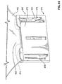
Figure 1 is a perspective view of a window regulator assembly in accordance with an embodiment of the present invention; -
Figure 2 is a magnified perspective view of a portion of the window regulator assembly shown inFigure 1 ; -
Figure 3 is a magnified perspective view of a portion of a carrier and is part of the window regulator assembly shown inFigure 1 ; -
Figure 4 is a magnified perspective view of a pulley assembly that is part of the window regulator shown inFigure 1 ; -
Figure 5 is a magnified sectional perspective view of the pulley assembly shown inFigure 4 ; -
Figure 6 is a magnified sectional perspective view of the pulley assembly shown inFigure 4 mounted to the portion of the carrier shown inFigure 3 ; -
Figure 7 is a magnified perspective view of an alternative structure for the portion of the carrier shown inFigure 3 ; -
Figure 8 is a magnified sectional side view of an alternative pulley assembly mounted to the alternative carrier structure shown inFigure 7 ; -
Figures 9a and 9b are magnified perspective views of a lifter plate that is part of the window regulator assembly shown inFigure 1 ; -
Figure 10 is a plan view of the lifter plate shown inFigures 9a and 9b ; -
Figure 11 is another magnified perspective view of the lifter plate shown inFigures 9a and 9b ; -
Figure 12 is a sectional view along section line 13-13 shown inFigure 10 ; -
Figures 13a and 13b are perspective views of another lifter plate that is part of the window regulator assembly shown inFigure 1 ; -
Figure 14 is a magnified sectional view of the lifter plate shown inFigures 9a and 9b , illustrating the engagement of the lifter plate with the vehicle window; -
Figure 15 is a further magnified sectional side view of the lifter plate shown inFigures 9a and 9b ; -
Figure 16 is a magnified perspective view of an alternative lifter plate for use with the window regulator assembly shown inFigure 1 ; -
Figure 17 is a perspective view of the window regulator assembly shown inFigure 1 , illustrating wiring harness clips in accordance with another aspect of the present invention; -
Figure 18 is a magnified perspective view of one of the wiring harness clips shown inFigure 17 ; -
Figure 19 is a plan view of the wiring harness clip shown inFigure 18 ; -
Figure 20 is an elevation view of the wiring harness clip shown inFigure 18 , showing a wiring harness captured therein; -
Figure 21 is a perspective view of the wiring harness clip shown inFigure 18 , with a wiring harness at a first stage of mounting therein; -
Figure 22 is a perspective view of the wiring harness clip shown inFigure 18 , with the wiring harness at a second stage of mounting therein; -
Figure 23 is a perspective view of the wiring harness clip shown inFigure 18 , with the wiring harness at a near final stage of mounting therein; -
Figure 24 is a magnified perspective view of a portion of a carrier shown inFigure 1 ; -
Figure 25 is a perspective view of the carrier shown inFigure 1 , with components mounted thereto removed to highlight other aspects of the present invention; -
Figure 26 is a magnified view of a portion of the carrier shown inFigure 25 , with a component mounted thereto; -
Figure 27 is a magnified view of another portion of the carrier shown inFigure 25 , to illustrate another aspect of the present invention; -
Figure 28 is a perspective view of a window regulator system having a down stop system in accordance with another embodiment of the present invention; -
Figure 29 is a magnified perspective view of the down stop system shown inFigure 28 ; -
Figure 30 is a perspective view of a window regulator system including a tensioner in accordance with another embodiment of the present invention; -
Figure 31 is a magnified perspective view of the tensioner shown inFigure 30 ; -
Figure 32 is perspective view of a single-cable window regulator system in accordance with another embodiment of the present invention; -
Figure 33 is a magnified perspective view of a lifter plate shown inFigure 32 ; -
Figure 34 is a magnified sectional perspective view of the lifter plate shown inFigure 33 ; -
Figure 35 is another magnified sectional perspective view of the lifter plate shown inFigure 33 , illustration a first stage of installation of a cable into the lifter plate; -
Figure 36 is another magnified sectional perspective view of the lifter plate shown inFigure 33 , illustration a second stage of installation of the cable into the lifter plate; -
Figure 37 is a perspective view of a lifter plate in accordance with another embodiment of the present invention; -
Figure 38 is a perspective view of a lifter plate in accordance with yet another embodiment of the present invention; -
Figure 39 is a sectional side view of the lifter plate shown inFigure 38 ; -
Figures 40a, 40b and 40c are sectional perspective views illustrating the insertion of a vehicle window into the lifter plate shown inFigure 38 ; -
Figure 41 is a perspective view of a lifter plate in accordance with yet another embodiment of the present invention; -
Figures 42a, 42b, 42c and 42d are sectional perspective views illustrating the insertion of a vehicle window into the lifter plate shown inFigure 41 ; -
Figure 43 is a perspective view of a lifter plate in accordance with yet another embodiment of the present invention; -
Figure 44 is a perspective view of the lifter plate shown inFigure 43 with a vehicle window inserted therein; and -
Figure 45 is a sectional side view of a prior art pulley and carrier, illustration the transmission of force therebetween. - Reference is made to
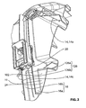
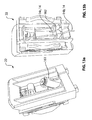
Figure 1 , which shows awindow regulator assembly 10 for moving avehicle window 11 up and down in accordance with an embodiment of the present invention. Thewindow regulator assembly 10 includes adrive motor 12, a set ofdrive cables 14, including afirst drive cable 14a, asecond drive cable 14b and athird drive cable 14c, acarrier 15, which includes a first set ofrails 16 and second set ofrails 18, afirst lifter plate 20 and asecond lifter plate 22. - The
drive motor 12 drives vertical movement of the first andsecond lifter plates rails drive cables 14. - The
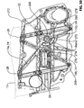
carrier 15 is itself mountable to the interior of a door assembly (not shown) that forms part of a vehicle. In the embodiment shown inFigure 1 , thecarrier 15 is a structural element, and is configured to withstand loads incurred during operation ofwindow regulator assembly 10. Thecarrier 15 includes acarrier body 24 and the aforementioned first and second set ofrails rails 16 may include afirst rail 16a and asecond rail 16b. Thefirst rail 16a is integrally mounted to thecarrier body 24. Thefirst rail 16a is an elongate rectangular structure. Thesecond rail 16b may be similar to thefirst rail 16a, and may be an elongate rectangular structure that is integral with thecarrier body 24. The first andsecond rails Figure 1 , the first andsecond rails carrier body 24. - It has been shown in
Figures 1 and2 for the first set ofrails 16 to include two rails (ie.rails rail 16a), or a greater number of rails, such as three rails. - The second set of
rails 18 may be similar in quantity and in structure to the first set ofrails 16. By configuring the first and second sets ofrails carrier body 24, thecarrier 15 may be more easily manufactured by a molding process, such as an injection molding process. - Reference is made to
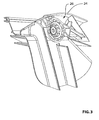
Figure 3 , which shows a pulley assembly mount 26 that is part of thecarrier body 24. Thepulley assembly mount 26 is configured to receive a pulley assembly 28 (Figure 4 ), that is used to effect a change in direction in one of the drive cables 14 (seeFigure 6 ). - Referring to
Figure 4 , thepulley assembly 28 includes apulley fastener 30, apulley bearing member 32, and apulley 34. - Referring to
Figure 6 , thepulley fastener 30 cooperates with apulley fastener mount 36 on thecarrier body 24 to hold thepulley assembly 28 on thecarrier 16. Thepulley fastener 30 may be any suitable type of fastener such as, for example, a threaded fastener. - The
pulley bearing member 32 is retained by thepulley fastener 30 in engagement with thecarrier body 24. Thepulley bearing member 32 includes a pulley assembly bendingload bearing surface 38 which may be a generally conical surface. The pulley assembly bendingload bearing surface 38 mates with a carrier bendingload bearing surface 40 that is part of thepulley assembly mount 26. By providing coned bendingload bearing surfaces pulley bearing member 32 and in thepulley assembly mount 26, the loads incurred during operation of thewindow regulator assembly 10 are spread over a larger surface area than occurs in some prior art devices. For example, in some prior art pulleys, the bending load exerted by a drive cable on a pulley passes through the pulley, and in turn from the pulley to the corner between the pulley fastener and the pulley fastener aperture in the carrier, as illustrated by theprior art pulley 42 and the priorart pulley fastener 44 and thecarrier 46 inFigure 45 . The cone angle between the pulley assembly bendingload bearing surface 38 and the axis about which the pulley rotates, which is thepulley rotation axis 48 shown inFigure 6 , may be any suitable angle such as, for example, approximately 45 degrees. Similarly, the cone angle of the carrier bendingload bearing surface 40 would be approximately the same angle as that of the pulley assembly bendingload bearing surface 38. - The
pulley 34 includes a pulleythrust bearing surface 50 that engages a carrierthrust bearing surface 51 during rotation of thepulley 34. In order to reduce the frictional drag between the pulleythrust bearing surface 50 and the carrierthrust bearing surface 51, the pulleythrust bearing surface 50 may have a relatively small radial width. This is possible in situations where thrust loads are not expected to be substantial. - The interface between the rotating portion of the
pulley assembly 28 and the fixed portion occurs at the pulley rotational bearing surface, shown at 52, and the pulley bearing member rotational bearing surface, shown at 53. It will be noted that the aforementioned interface is moved relatively far out radially from the center of rotation of thepulley 34. This reduces, among other things, the moment that is applied from the pulley to thepulley bearing member 32 and to thepulley fastener 30, in the plane of rotation of thepulley 34, during operation of the window regulator assembly 10 (Figure 1 ). - Referring to
Figure 4 , thepulley 34 includesnotches 54 that can be used when partially mounting acable 14, as part of a technique for installing a cable onto thepulley 34. - The
pulley fastener 30 and thepulley bearing member 32 may be manufactured from any suitable materials, such as a suitable steel. It will be understood that it is optionally possible for thepulley fastener 30 and thepulley bearing member 32 to be manufactured as a single integral component. - The
pulley 34 may be manufactured from any suitable material, such as, for example, a polymeric material, such as Delrin™. - Reference is made to
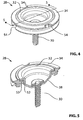
Figures 7 and 8 , which shows apulley assembly mount 55 and apulley assembly 56 in accordance with another embodiment of the present invention. Thepulley assembly mount 55 may be similar to the pulley assembly mount 26 (Figure 3 ), with one difference being that thepulley assembly mount 55 has a carrier bendingload bearing surface 58 that is a solid surface, instead of the carrier bendingload bending surface 40 shown inFigure 6 , which is formed from a matrix of structural ribs. - Referring to
Figure 8 , thepulley assembly 56 differs principally from the pulley assembly 28 (Figure 6 ), in that thepulley fastener 60 shown inFigure 8 is not a threaded fastener, and instead pushes in to retain thepulley bearing member 62 from the other side of a passed through aperture shown at 64. - Reference is made to
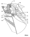
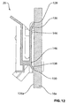
Figures 9a and 9b , which show thelifter plate 20. Thelifter plate 20 includes alifter plate body 65 with afirst side wall 66 and asecond side wall 68. The first andsecond side walls vehicle window 11 therebetween (seefigure 14 ). As further shown inFigure 14 , thelifter plate 20 includes awindow holding member 76 for holding thewindow 11 in position in thelifter plate 20 thereby preventing the inadvertent withdrawal of thevehicle window 11 from thelifter plate 20. Thewindow holding member 76 may pass through a lockingaperture 78 in thevehicle window 11 and may thus be referred to in such embodiments as a window pass-throughmember 76. The window pass-throughmember 76 has an attachedend 80 where it is connected to thefirst side wall 66 and afree end 82. At the attachedend 80, the window pass-throughmember 76 is connected to a biasingmember 84 which in turn is connected to thefirst side wall 66. The window pass-throughmember 76 further includes a deflection surface 86 (seeFigure 15 ) that is sloped downwardly toward thefree end 82. When thevehicle window 11 is introduced between the first andsecond side walls deflection surface 86 thereby pushing the window pass-throughmember 76 out of the way temporarily. As thevehicle window 11 is further introduced into the space between the first andsecond side walls member 76 is biased by the biasingmember 84 to return to its original position, which it can do when the lockingaperture 78 passes in front of it. When the window pass-throughmember 76 returns to its original position through the lockingaperture 78 it locks thevehicle window 11 to thelifter plate 20. - Referring to
Figure 15 , thesecond side wall 68 includes a free endvertical limit surface 90 that is positioned to limit the upward movement of thefree end 82 of the window pass-throughmember 76 in the event that thevehicle window 11 is attempted to be withdrawn vertically from between the first andsecond side walls first side wall 66 may optionally include a connected endvertical limit surface 92 that is positioned to limit the vertical movement of theconnected end 80 of the window pass-throughmember 76, in the event that thevehicle window 11 is attempted to be withdrawn vertically from the between the first andsecond side walls vertical limit surface 90 reduces the bending moment that would be exerted on the window pass-throughmember 76 by thevehicle window 11 in the event that thevehicle window 11 is attempted to be withdrawn vertically from between the first andsecond side walls vertical limit surface 92 relieves the biasingmember 84 from having to resist vertical movement of theconnected end 80 in the event of an attempted withdrawal vertically of thevehicle window 11 from between the first andsecond side walls member 84 to be configured to have relatively low resistance to flexion. Reducing the resistance to flexion of the biasingmember 84 thereby facilitates insertion of the window bottom 88 (Figure 14 ) past the window pass-throughmember 76, during the initial insertion of thevehicle window 11 between the first andsecond side walls second side walls - As a further measure of security, a
horizontal limit surface 94 may be provided on thefirst side wall 66 to prevent the inadvertent retraction horizontally of the window pass-throughmember 76 during a withdrawal vertically of thevehicle window 11 from thelifter plate 20. Thehorizontal limit surface 94 on thefirst side wall 66 is positioned to engage a correspondinghorizontal limit surface 96 on the window pass-throughmember 76 in the event that the window pass-throughmember 76 is pulled upwards from its original position shown inFigures 14 and15 , but does not engage thehorizontal limit surface 96 on the window pass-throughmember 76 in the event that the window pass-throughmember 76 is moved downwards. Thus, during insertion of thevehicle window 11, the window pass-throughmember 76 can retract, but in the event of upward movement of thevehicle window 11 the window pass-throughmember 76 is prevented from being retracted horizontally. - Reference is made to
Figure 38 , which shows alifter plate 400 in accordance with another embodiment of the present invention. Thelifter plate 400 includes a different structure for locking thewindow 11 therein, than thelifter plate 20. Thelifter plate 400 includes alifter plate body 402 having afirst side wall 404 and a second side wall 406 (Figure 39 ), which are joined at their respective bottoms. A window pass-throughmember 408 has aconnected end 410 and afree end 412 and is configured to pass through the lockingaperture 78 of thewindow 11. - The
connected end 410 may be connected to thefirst side wall 404 by means of a biasingmember 414 that biases the window pass-throughmember 408 towards the locking position shown inFigure 39 . A lockingmember 416 prevents the window pass-throughmember 408 from being pushed out of the way by thewindow 11 if thewindow 11 is urged to pull out from thelifter plate 400 for some reason. The lockingmember 416, however, permits the window pass-throughmember 408 to be pushed out of the way during entry of thewindow 11 into thelifter plate 400.Figures 40a, 40b and 40c illustrate the insertion of thewindow 11 into thelifter plate 400. - Reference is made to
Figure 41 , which shows alifter plate 420 in accordance with another embodiment of the present invention. Thelifter plate 420 includes a lifter plate body 422 having afirst side wall 424 and asecond side wall 426 joined at their respective bottoms. Thefirst side wall 424 has anaperture 428 therethrough and a pivot shaft 430 (Figure 42a ) that extends across theaperture 428. Awindow holding member 432 is a separate member that is removably and pivotably mounted onto thepivot shaft 430. - The
window holding member 432 includes a window pass-throughmember 434 that passes through the lockingaperture 78 of thewindow 11 to lock thewindow 11 in place in thelifter plate 420. Thewindow holding member 432 further includes a drivingsurface 440, which is engaged by thewindow 11 during insertion of thewindow 11 into thelifter plate 420. When thewindow 11 engages the drivingsurface 440 and continues to move downward, the motion of thewindow 11 causes thewindow holding member 432 to rotate (clockwise in the view shown inFigures 42a-d ) from a window-receiving position shown inFigure 42a towards a window holding position shown inFigure 42d . Thefirst side wall 424 further includes avertical limit surface 442 that is positioned to be proximate avertical limit surface 444 on thewindow holding member 432 when thewindow holding member 432 is in the window locking position. In the event that thewindow 11 is attempted to be withdrawn from thelifter plate 420, thevertical limit surface 442 engages thewindow holding member 432 to prevent vertical movement thereof. Additionally, thewindow holding member 432 includes a lockingmember 446 that engages a lockingmember 448 on thefirst side wall 424 to prevent thewindow holding member 432 from being rotated out of the way by thewindow 11 during an event wherein thewindow 11 is attempted to be withdrawn from thelifter plate 420. The lockingmember 446 may be biased by aresilient arm 450 towards a locking position (Figures 42a-d ). In the event that thewindow 11 needs to be withdrawn from thelifter plate 420 for service or maintenance the service person can, using a suitable tool, depress the lockingmember 446 so that it clears the lockingmember 448. The service person can lift thewindow 11 upwards while assisting the rotation of thewindow holding member 432 out of the way (counter-clockwise in the views shown inFigures 42a-d ). - A large aperture 452 (
Figure 41 ) is provided in thesecond side wall 426 so as to permit thewindow holding member 432 to be installed on the pivot shaft 430 (Figure 42a ) prior to insertion of thewindow 11 into thelifter plate 420. - Reference is made to
Figure 43 , which shows alifter plate 460 in accordance with another embodiment of the present invention. Thelifter plate 460 is configured to engage awindow 462 that does not possess a locking aperture, but instead possessesundercuts 464 along opposingsides 466 of anengagement feature 468. - The
lifter plate 460 includes alifter plate body 470 having afirst side wall 472 and asecond side wall 474. A pair ofwindow holding members 476 are provided on thefirst side wall 472 and engage theundercuts 464 to prevent withdrawal of thewindow 462 once thewindow 462 has been inserted into position in thelifter plate 460. Thewindow holding members 476 are biased towards a locking position (Figure 43 ) by biasingmembers 478. The biasingmembers 478 may be pushed outwards from the plane of thefirst side wall 472 against the urging of the biasingmembers 478 by thewindow 462 as it slides therepast. Once thewindow 462 is in position, the biasingmembers 478 urge thewindow holding members 476 back to their locking positions so that they are positioned to engage the undercuts 464 (Figure 44 ). - Once in position in the
lifter plate 460, if thewindow 462 is urged to withdraw from thelifter plate 460, theundercuts 464 urge thewindow holding members 476 outwards in directions that are substantially parallel to the plane of thefirst side wall 472. A pair of window holding member locking surfaces 480 that are present on thefirst side wall 472 prevent thewindow holding members 476 from deflecting out of the way. The first and secondwindow holding members 476 thus hold thewindow 462 in place. - It will be noted that, while the embodiment shown in
Figures 43 and44 includes a pair ofwindow holding members 476 which engage a pair ofundercuts 464, it is alternatively possible to provide more or fewer undercuts and correspondingwindow holding members 476. It is possible for example, to include a single undercut 464 and a singlewindow holding member 476. - Reference is made to
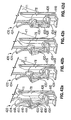
Figure 10 . Thelifter plate 20 has a longitudinal axis Alonglp. Thelifter plate body 65 includes a first forward lateralguide surface engager 98, a first rearward lateralguide surface engager 99, a second forward lateralguide surface engager 100 and a second rearward lateralguide surface engager 101. The first lateralguide surface engagers guide surface engagers lateral guide surface 102 and a secondlateral guide surface 104 respectively, for guiding movement of thelifter plate 20 in the longitudinal direction. The first and second lateral guide surfaces 102 and 104 are surfaces on the first andsecond rails Figure 10 , the first and second lateral guide surfaces 102 and 104 are the outer side surfaces of therails rails guide surface engagers - The
lifter plate 20 may include a first forward lateral guide surfaceengager biasing member 110, a first rearward lateral guide surfaceengager biasing member 112, a second forward lateral guide surfaceengager biasing member 114 and a second rearward lateral guide surfaceengager biasing member 116, each of which is positioned to bias its associated lateralguide surface engager lateral guide surface - The biasing
members lifter plate 20, shown at 118 and 120 respectively to accommodate some movement in the lateral direction, in the event of forces urging thelifter plate 20 in that manner, while maintaining engagement with the first and second lateral guide surfaces 102 and 104. By permitting thelifter plate 20 to accommodate such movement, the likelihood of binding of thelifter plate 20 during its travel along therails lifter plate 20 during use. By reducing the likelihood of binding during use, BSR (buzz, squeak and rattle) that may be associated with operation of thelifter plate 20 may be reduced. Additionally, in embodiments wherein the likelihood of binding is sufficiently low, the drive motor 12 (Figure 1 ) that can be provided may be relatively less expensive than would otherwise be required. - It has been shown in
Figure 10 for thelifter plate 20 to include a forward set of lateral guide surface engagers including first and second forward lateralguide surface engagers guide surface engagers lifter plate 20 to include more or fewer sets of lateral guide surface engagers and associated biasing members. For example, thelifter plate 20 could include a single set of first and second lateral guide surface engagers. By having two sets of lateral guide surface engagers (ie. the forward set of lateralguide surface engagers guide surface engagers 99 and 101), the overall surface area of contact between thelifter plate 20 and the lateral guide surfaces 102 and 104 is lower than would be necessary if thelifter plate 20 only had a single first lateral guide surface engager and a single second lateral guide surface engager. This is because if only a single first lateral guide surface engager and a single second lateral guide surface engager were provided, one or both of them would have to be relatively long to stabilize thelifter plate 20 and prevent it from rotating in the lateral/longitudinal plane (ie. the plane that is generally parallel to the first andsecond side walls 66 and 68) due to any uneven forces that arise during use. Having a reduced area of contact between thelifter plate 20 and the lateral guide surfaces 102 and 104 reduces the frictional drag on thelifter plate 20 during its travel up and down therails lifter plate 20. Additionally, the reduced frictional drag may result in sufficiently lower load on the drive motor 12 (Figure 1 ), that a less expensive motor, that may be, for example, less powerful and/or smaller, may be used in thewindow regulator assembly 10. - It has been shown for the right side lateral guide surface engagers (ie. the first side lateral
guide surface engagers 98 and 99) to include first lateral guide surfaceengager biasing members guide surface engagers 100 and 101) to include first lateral guide surfaceengager biasing members guide surface engagers lifter plate body 65, so that only the first lateralguide surface engagers lifter plate 20 to accommodate uneven forces exerted thereon during use, that might urge thelifter plate 20 to rotate in the lateral/longitudinal plane. It will be understood that it is possible instead to have the single forward and rearward biasing members on the left side, shown at 124. It will further be understood that, in an embodiment wherein there is only one first lateral guide surface engager and one second lateral guide surface engager, it is optionally possible to fixedly connect one of them to thelifter plate body 20 and to provide a biasing member for the other. - Referring to
Figure 2 , in addition to being guided with lateral guide surfaces 102 and 104, thelifter plate 20 is also guided by a movement-plane guide surface 126, which may be made up of a first window-movement-planeguide surface portion 126a and a second window-movement-planeguide surface portion 126b. Theguide surface 126 is referred to as a window-movement-plane guide surface 126 because it assists in defining the plane of movement of thevehicle window 11. - Instead of the two window-movement-plane
guide surface portions rails plane guide surface 126. - Referring to
Figure 11 , to engage the window-movement-plane guide surface 126 (Figure 2 ), thelifter plate 20 may further include a first forward window-movement-planeguide surface engager 128, a first rearward window-movement-planeguide surface engager 130, a second forward window-movement-planeguide surface engager 132 and a second rearward window-movement-planeguide surface engager 134. The first forward and rearward window-movement-planeguide surface engagers guide surface portion 126a (Figure 2 ). The second forward and rearward window-movement-plane guide surface engagers 132 (Figure 11 ) and 134 (Figure 11 ) are positioned to engage the window-movement-planeguide surface portion 126b (Figure 2 ). A sectional view illustrating the engagement of the first forward and rearward window-movement-planeguide surface engagers guide surface portion 126a on therail 16a is shown inFigure 12 . - Referring to
Figure 11 , by having two or more longitudinally spaced window-movement-plane guide surface engagers, (ie. the forward window-movement-planeguide surface engager guide surface engager 130 or 134), the overall surface area of contact between thelifter plate 20 and the window-movement-plane guide surface 126 (Figure 2 ) is lower than would be necessary for stability if thelifter plate 20 only had a single window-movement-plane guide surface engager. Having a reduced area of contact between thelifter plate 20 and the window-movement-plane guide surface 126 reduces the frictional drag on thelifter plate 20 during its travel up and down therails lifter plate 20 have been explained above in relation to the engagement with the lateralguide surface engagers Figure 11 ). - Similarly, by having two or more laterally spaced window-movement-plane guide surface engagers, (ie. a set comprising a left side window-movement-plane guide surface engager and a right side window-movement-plane guide surface engager), the overall surface area of contact between the
lifter plate 20 and the window-movement-plane guide surface 126 is lower than would be necessary for stability if thelifter plate 20 only had a single window-movement-plane guide surface engager. - Thus, it is particularly advantageous with respect to reduced surface area of contact to have two laterally spaced forward window-movement-plane
guide surface engagers 128 and 132 (Figure 11 ), and two laterally spaced rearward window-movement-planeguide surface engagers guide surface engagers - A first forward window-movement-plane guide surface
engager biasing member 136, a first rearward window-movement-plane guide surfaceengager biasing member 138, a second forward window-movement-plane guide surfaceengager biasing member 140 and a second rearward window-movement-plane guide surface engager biasing member 142 may be provided to bias the window-movement-planeguide surface engagers plane guide surface 126. By providing the biasingmembers lifter plate 20 is capable of accommodating some forces urging it into the window-movement-plane guide surface 126 without binding on the window-movement-plane guide surface 126. - If forces acting on the
lifter plate 20 cause a selected degree of flexion in any of the window-movement-plane guide surfaceengager biasing members lifter plate 20 includes secondary window-movement-planeguide surface engagers Figure 2 ), thereby preventing further flexion of the associated window-movement-plane guide surfaceengager biasing member Figure 12 shows the secondary window-movement-planeguide surface engagers Figure 11 , in embodiments wherein the secondary window-movement-planeguide surface engagers guide surface engagers - The secondary window-movement-plane
guide surface engagers lifter plate 20 is not unduly increased as a result of their engagement with the window-movement-plane guide surface 126 (Figure 2 ). - It will be noted that, although the
lifter plate 20 is 'captured' laterally by the opposing lateral guide surfaces 102 and 104 (Figure 10 ), it is not 'captured', however, by opposing window-movement-plane surfaces. Thelifter plate 20 is nonetheless prevented from movement relative to the window-movement plane (ie. towards or away from the window-movement plane) by virtue of its connection to thevehicle window 11, which itself is prevented from movement relative to the window-movement-plane by the glass run channels, one of which is shown at 151 inFigure 1 . - Reference is made to
Figure 14 . Thelifter plate 20 includes afirst cable mount 152 and asecond cable mount 154 for receiving the ends of thecables ferrules 156 and 158 mounted thereon respectively. In the embodiment shown inFigure 14 , thecable mount 152 includes an optional cable end biasing member 160, that acts to cushion the engagement between thedrive cables lifter plate 20 to reduce the likelihood of damage to thelifter plate 20 during sudden changes in forces acting thereon by thecables Figure 1 ) is actuated, there will be an initial jerk by one of thecables lifter plate 20, and an initial resistive force acting on thelifter plate 20 by the other of thecables lifter plate 20. It will be noted that this single cable end biasing member 160 absorbs jerk energy regardless of whether the motive jerk is exerted by thecable 14c or whether the motive jerk is exerted by thecable 14a. Additionally, the biasing member 160, which may be, for example, a compression spring, acts to maintain the associatedcable 14c in tension during upward movement of thewindow 11 - Referring to
Figure 10 , the cable mounts 152 and 154 are both positioned laterally between the first set of lateralguide surface engagers guide surface engagers lifter plate 20 by thecables lifter plate 20 during movement of thelifter plate 20 on therails - In a particularly preferred embodiment, it is optionally possible for the cable mounts 152 and 154 to in line with each other, in the sense that they have the same lateral position as each other. In other words, they both have the same distance to the first set of lateral
guide surface engagers guide surface engagers first cable mount 152 is 1 inch, as an example, from the first set of lateralguide surface engagers second cable mount 154 is also 1 inch from the first set of lateralguide surface engagers lifter plate 20 by thecables lifter plate 20 is relatively lower than embodiments wherein the first and second cable mounts 152 and 154 occupy different lateral positions than each other. - In a more particularly preferred embodiment, the cable mounts 152 and 154 are both centered between the first and second sets of lateral
guide surface engagers cables lifter plate 20 in the lateral/longitudinal plane is theoretically zero. In practice the net moment in this more particularly preferred embodiment may be some non-zero value due to tolerances and the like, however, it is expected that it is a relatively small value relative to other optional embodiments described above. - Referring to
Figures 13a and 13b , thesecond lifter plate 22 may be similar to thefirst lifter plate 20, with some difference optionally being present in the configuration of the cable mounts, shown at 161 and 162. A spring (not shown) is optionally provided in thecable mount 161 to provide similar function (eg. tensioning of thecable 14c). - Reference is made to
Figure 16 , which shows analternative lifter plate 163 in accordance with another embodiment of the present invention. Thelifter plate 163 may be similar to thelifter plates 20 and 22 (Figures 9a and13a ), except that thelifter plate 163 is particularly configured for use with a rear window of a vehicle. To this end, thelifter plate 163 includes additional features, such as a second window pass-throughmember 76 which passes through asecond locking aperture 78 on thevehicle window 11. Thelifter plate 163 may be similar to two lifter plates 20 (or 22) connected together for connecting to two lockingapertures 78 that are proximate to each other on thevehicle window 11, thereby strengthening the connection to thevehicle window 11. However, thelifter plate 163 is configured to engage only one set of guide rails. Additionally, the side walls of thelifter plate 163, shown at 164 and 166, define achannel 168 that has a curvedbottom face 170 so as to be configured to mate with thecurved bottom edge 172 of a mountingear 174 on thevehicle window 11 that contains the two lockingapertures 78. By configuring thechannel 168 to mate with the mountingear 174, thelifter plate 163 is more easily adjusted to the correct position to align the window pass throughmembers 76 with the lockingapertures 78 of thevehicle window 11. - Reference is made to
Figure 17 , which shows awiring harness clip 176 on thecarrier 15 that may be used to hold a wiring harness, shown at 178. Thewiring harness 178 may be sheathed to facilitate its handling. Thewiring harness clip 176 is shown in more detail inFigure 18 . Thewiring harness clip 176 includes afirst clip element 180, asecond clip element 182, awiring harness guide 184, a firstclip element guard 186 and a secondclip element guard 188. Referring toFigure 19 , the first andsecond clip elements wiring harness 178 in a longitudinal orientation along a longitudinal axis Alongwh. In particular, the first andsecond clip elements wiring harness guide 184, together define a longitudinally oriented wiringharness retaining aperture 190, shown inFigure 20 , and in this way define the longitudinal axis Alongwh. - The first and
second clip elements inlet 192, shown inFigure 19 . More particularly, theinlet 190 is defined by a first clip elementinlet defining surface 194 and a second clip elementinlet defining surface 196. The first and second clip elementinlet defining surfaces wiring harness 178, shown at Dwh (Figure 20 ). Additionally, the first and second clip elementinlet defining surfaces Figure 19 ) from the longitudinal axis Alongwh. - The first and
second clip elements surfaces Figure 20 ), each of which extends at a selected angle ANlead from the surface of thecarrier 15 to facilitate entry of thewiring harness 178 into the inlet 192 (Figure 19 ). - The first and
second clip elements element biasing members second clip elements Figure 20 ). When thewiring harness 178 is introduced into theinlet 192, as shown inFigure 21 , the engagement with the lead-insurfaces second clip elements members wiring harness 178 is inserted and is captured by the first andsecond clip elements 180 and 182 (seeFigure 22 ) it can be rotated so that it is held in alignment with the longitudinal axis Alongwh by thewiring harness guide 184. Theguide 184 includes a first longitudinally extendingguide element 206 and a second longitudinally extendingguide element 208 that is spaced from the first longitudinally extendingguide element 206. Theguide elements Figure 20 ) along their lengths, at selected points on the perimeter of thewiring harness 178 so as to provided a selected degree of resistance to twisting of thewiring harness 178 out of its longitudinal alignment, once it is in place. - The distance between the first and
second clip elements Figure 20 ) is shown at Dtrans and is sufficiently small to inhibit the inadvertent removal of thewiring harness 178 when it is aligned in a longitudinal direction (seeFigure 23 ). In particular, the distance Dtrans is smaller than the distance Din, which means that it is relatively easier to introduce thewiring harness 178 into theinlet 192 and relatively harder to remove an installedwiring harness 178. - The capture surfaces of the first and
second clip elements wiring harness 178, and window-movement-plane capture surfaces 214 and 216, which resist direct withdrawal of thewiring harness 178 away from thecarrier 15. The window-movement-plane capture surfaces 214 and 216 each extend at a selected angle ANcapt relative to thecarrier 15. The angle ANcapt is selected so that a force in a direction perpendicular to the plane of thecarrier 15, which would urge direct withdrawal of thewiring harness 178 from thewiring harness clip 176, results in a relatively low moment acting on the first andsecond clip elements members - The first and second clip element guards 186 and 188 are positioned to inhibit damage to the first and
second clip elements wiring harness clip 176. - The
wiring harness clip 176 may be configured to be manufactured easily using from a suitable polymeric material, using an injection molding process with a simple mold plate arrangement requiring two mold plates. Thus, the manufacture of thewiring harness clip 176 can be effected relatively inexpensively. - The
wiring harness clip 176 may be mounted to the carrier 15 (Figure 17 ) by any suitable means, such as by a suitable adhesive, or by thermally joining it to thecarrier 15. - It will be appreciated that the
wiring harness clip 176 may be used to retain wiring harnesses 178 in areas of the vehicle outside the door assembly (not shown). For example, wiring harnesses 176 are generally run along paths throughout the vehicle to provide power to numerous elements, including, for example, the vehicle taillights. Thewiring harness clip 176 could also be used in other structures, such as trailers. - Reference is made to
Figure 1 , which shows another feature that is integrally provided in thecarrier 15, in accordance with another aspect of the present invention. Thecarrier 15 includes first and second integral down stops 218 and 220, which provide lower travel limits for thelifter plates stop 220 is shown in further detail inFigure 24 . - Reference is made to
Figure 1 , which shows yet another feature that is integrally provided in thecarrier 15, in accordance with another aspect of the present invention. Thecarrier 15 includes a co-molded carrier seal, shown at 222, which is used to seal thecarrier 15 with other elements of a door assembly (not shown). The carrier seal 222 may be made from any suitable material, such as a suitably soft compressible polymeric material. Co-molding the carrier seal 222 with thecarrier body 24 reduces the cost of manufacture of thecarrier 15, and may eliminate the need for a separate item (ie. a carrier seal) to be warehoused, and eliminates a manufacturing step in the manufacture of the carrier 15 (ie. the mounting of a carrier seal to the carrier body). - Reference is made to
Figure 25 , which shows amotor housing seal 224, which may additionally be co-molded with thecarrier body 24, to similar advantage to the co-molding of the carrier seal 222. - Reference is made to
Figure 26 , which shows an insidedoor handle mount 226 that is integral with the carrier body. To provide the insidedoor handle mount 226, a raw inside door handle mount is molded along with thecarrier body 24. Pivotpin receiving apertures 228 are then machined or otherwise formed in the raw inside door handle mount to receive apivot pin 230 for aninside door handle 232. Molding the raw inside door handle mount and then machining or otherwise forming the pivotpin receiving apertures 228 may be a relatively inexpensive way of providing the insidedoor handle mount 226, compared with providing a separate door handle mount that is then mounted to thecarrier 15. - A door
latch operator cable 234 may be connected between thedoor handle 232 and a door latch mechanism 236 (seeFigure 17 ). Referring toFigure 27 , thecarrier 15 includes two latch mounts 238 and 240 on alatch presenter 242 that may be integrally connected with thecarrier 15. The two latch mounts 238 and 240 help retain the latch in place on thecarrier 15 until it is installed into the door assembly (not shown). - Reference is made to
Figure 28 , which shows an alternative downstop system 250 for use with awindow regulator assembly 252. Thewindow regulator assembly 252 may be similar to the window regulator assembly 10 (Figure 1 ) except that it includes aferrule 254 on thethird cable 14c, acarrier 256 instead of the carrier 15 (Figure 1 ), and afirst lifter plate 258 instead of the first lifter plate 20 (Figure 1 ). Theferrule 254 is positioned at a selected position on thethird cable 14c. Thecarrier 256 may be similar to the carrier 15 (Figure 1 ) except that thecarrier 256 includes adown stop 260 that is positioned to stop theferrule 254 on thethird cable 14c when thelifter plates rails Figure 29 , thedown stop 260 may include adown stop body 262 that is integrally connected with thecarrier 256, and may further include a resilient,compressible bumper 264 that may be inserted into a receivingaperture 266 in thedown stop body 262. Thebumper 264 and thedown stop body 262 are slotted to permit the introduction of thecable 14c therein during installation of thecable 14c on thecarrier 256. - As a result of associating the
down stop system 250 with one of thecables Figure 28 it iscable 14c), thefirst lifter plate 20 is not directly involved in stopping its own downward travel. As a result, a source of stress is removed from thelifter plate 258. By contrast, in some window regulator assemblies that incorporate a down stop that directly engages the lifter plate, the lifter plate can see increased stresses and can incur twisting. The twisting and other reactions of the lifter plate to the stresses during direct engagement with a down stop can contribute to BSR associated with the window regulator assembly. By stopping the downward travel of thelifter plate 258 using theferrule 254 and thethird cable 14c (ie. by achieving it without direct engagement between thelifter plate 258 and a down stop), the stresses on thelifter plate 20 are reduced, which, in turn, reduces a potential source of BSR for thewindow regulator assembly 252. - It will be understood that the
ferrule 254 is but one example of a down stop engagement member that can be connected to thecable 14c for engagement with thedown stop 260. - The
lifter plate 258 itself may be similar to the lifter plate 20 (Figure 1 ) except that thelifter plate 258 does not require bumpers to be incorporated therein, since it no longer directly engages thedown stop 260. - Reference is made to
Figure 1 . During operation of thewindow regulator system 10, thewindow 11 may either be moved upwards or downwards. During movement of the window upwards and particularly when thewindow 11 reaches its uppermost position, thecable 14a is under tension, while thecable 14b is relatively slack. This is because the drive motor cable drum, shown at 268, rotates in a direction which winds up thecable 14a thereon, and which lets outcable 14b therefrom. When this occurs, the slackness in thecable 14b increases the risk that it will leave the bearing surface shown at 269 (seeFigure 24 ) at the bottom of thewindow regulator assembly 10. Similarly, when thewindow 11 moves downwards and in particular when thewindow 11 bottoms out, there is tension in thecable 14b and relative slackness in thecable 14a, which increases the risk that thecable 14a will leave its associatedpulley assembly 28. In order to reduce the risk of thecables respective pulley 34 andbearing surface 269, springs, such as the spring 160 shown inFigure 14 may be incorporated into the connection between thecables respective lifter plates cables cables pulley 34 andbearing surface 269 is the tensioner shown at 270 inFigure 30 . - The
tensioner 270 is pivotally mounted to the carrier, shown at 272, about a pivot axis Atens. Thetensioner 270 includes atensioner body 274 with a firstcable engagement member 276 and a secondcable engagement member 278, which engage first and second lengths of cable, namely thecables Figure 31 ). - The
tensioner 270 may be configured so that no matter what position it is in, it causes some bending in both of thecables cables cable cable engagement member tensioner 270 to pivot, thereby urging the othercable engagement member other cable other cable cables cable respective pulley 34 or bearingsurface 269. - As a result of the
tensioner 270, springs, such as the spring 160 shown inFigure 14 , are not needed to mount the ends of thecables lifter plates lifter plates vehicle window 11. - Referring to
Figure 30 , the firstcable engagement member 276 is configured to transmit force from thecable 14a along a first moment arm D1 relative to the pivot axis Atens, and is configured to transmit force from thecable 14b along a second moment arm D2 relative to the pivot axis Atens. The first and second moment arms D1 and D2 may be approximately equal to each other. As a result, the force that is developed at the firstcable engagement member 276 has the same magnitude as the force developed at the secondcable engagement member 278. Accordingly, the tension developed in thefirst cable 14a is approximately the same as the tension developed in thesecond cable 14b. It will be appreciated that the first and secondcable engagement members cables - Another advantage to eliminating the need for springs when mounting the ends of the
cables lifter plates cables Figure 32 ) that has both of its ends connected to the drivemotor cable drum 262. Thecable 280 may include afirst ferrule 282 and asecond ferrule 283, which are mounted at first and second selected positions along the length of thecable 280 for receipt in first andsecond ferrule receptacles 284 and 285 in the lifter plates shown at 286 and 288 (Figure 32 ). In the embodiment shown inFigure 32 , the firstcable engagement member 276 on thetensioner 270 engages a first length of cable, namely theportion 280a of thecable 280 between thedrive motor 12 and thefirst lifter plate 286, and the secondcable engagement member 278 on thetensioner 270 engages a second length of cable, namely theportion 280b of thecable 280 between thedrive motor 12 and the second lifter plate 288. - The
cable 280 may be installed in thelifter plates 286 and 288 in any suitable way. An exemplary installation of thecable 280 in thelifter plate 286 is illustrated inFigures 34 ,35 and 36 . A user slides thecable 280 into the groove shown at 294 inFigure 33 , so that the cable is positioned as shown inFigure 35 . Thecable 280 is then advanced (ie. moved in the direction of arrow ADV) so that theferrule 282 passes through the aperture shown at 296 inFigure 36 . Theferrule 282 can then be moved into position in theferrule receptacle 284 into the position shown inFigure 34 . Theferrule 282 may be held in theferrule receptacle 284 by means of apress fit 284 or by some other suitable means. Alternatively theferrule 282 may remain in theferrule receptacle 284 simply by means of the orientation of thecable 280 during use. Thecable 280 may be installed in the lifter plate 288 in the same way as it is installed in thelifter plate 286. - By using a single cable 280 (
Figure 32 ) instead of threeseparate cables Figure 1 ), the amount of 'tolerance stack-up' is reduced in the window regulator system shown at 290 (Figure 32 ), relative to a three-cable system because each cable represents a potential source of dimensional error. - A three-cable system, if not assembled and manufactured properly, can exhibit bias in the sense that the two lifter plates may not be aligned correctly in the vertical positions on their respective rails. As a result, the vehicle window can chutter as it is moved. Because a single-cable window regulator system, such as the
window regulator system 290, has reduced tolerance stack-up, there is a reduced likelihood of the lifter plates being misaligned with each other height-wise and so the likelihood of chutter during movement of the vehicle window is reduced. - Reference is made to
Figure 37 , which shows alifter plate 298, with a different configuration for lateral guide surface engagers, shown at 300 and a different configuration for lateral guide surface engager biasing members, shown at 302, in accordance with another embodiment of the present invention. - While the above description constitutes a plurality of embodiments of the present invention, it will be appreciated that the present invention is susceptible to further modification and change without departing from the fair meaning of the accompanying claims.
Claims (14)
- A lifter plate, comprising:a lifter plate body including a first side wall and a second side wall configured to receive a vehicle window pane between the first side wall and the second side wall;a window holding member positionable in a locking position to prevent the withdrawal of the vehicle window pane from between the first and second side walls, wherein the window holding member is a window pass-through member configured to pass through a locking aperture of the vehicle window pane;a locking member positioned to prevent the movement of the window holding member out of the locking position in the event of a force urging the withdrawal of the vehicle window pane from between first and second side walls; anda biasing member having a resistance to flexion by the window and positioned to bias the window holding member towards the locking position,wherein the window holding member is movable against the biasing member out of the locking position by the vehicle window pane during insertion of the vehicle window pane between the first and second side walls, and the window holding member is biased by the biasing member to return to the locking position by passing through the locking aperture of the vehicle window pane, and the locking member prevention of the movement of the window holding member out of the locking position is independent of the resistance to flexion of the biasing member.
- A lifter plate as claimed in claim 1, wherein the locking member includes a free end vertical limit surface that is vertically aligned with a free end of the window holding member and positioned to engage the free end to limit upward movement of the free end.
- A lifter plate as claimed in claim 1 or 2, wherein the window holding member has a connected end, wherein the connected end is connected to the first side wall.
- A lifter plate as claimed in one of claims 1 to 3, wherein the locking member includes a connected end vertical limit surface that is vertically aligned with the connected end of the window holding member, and the connected end vertical limit surface is positioned to engage the connected end of the window holding member to limit upward movement of the window holding member.
- A lifter plate as claimed in one of claims 1 to 4, wherein the biasing member is integral with the window holding member and with the first side wall.
- A lifter plate as claimed in one of claims 1 to 5, wherein the window holding member has a deflection surface that is sloped towards the free end.
- A lifter plate as claimed in one of claims 1 to 6, wherein the locking member includes a side wall horizontal limit surface horizontally aligned with and configured to engage a corresponding horizontal limit surface of the window holding member to limit horizontal movement of the window holding member in the event of an upward force on the vehicle window pane held in the lifter plate.
- A lifter plate, comprising:a lifter plate body including a first side wall and a second side wall configured to receive a vehicle window pane between the first side wall and the second side wall;a window holding member positionable in a locking position to prevent the withdrawal of the vehicle window pane from between the first and second side walls, wherein the window holding member is a window pass-through member configured to pass through a locking aperture of the vehicle window pane;a locking member positioned to prevent the movement of the window holding member out of the locking position in the event of a force urging the withdrawal of the vehicle window pane from between first and second side walls; anda biasing member having a resistance to flexion by the window and positioned to bias the window holding member towards the locking position,wherein the window holding member is movable against the biasing member out of the locking position by the vehicle window pane during insertion of the vehicle window pane between the first and second side walls, the window holding member is biased by the biasing member to return to the locking position by passing through the locking aperture of the vehicle window pane, and the resistance to flexion of the biasing member is lower than would be required if the biasing member resistance to flexion was used without the locking member to perform both the biasing of the window holding member towards the locking position and the prevention of movement of the window holding member out of the locking position in the event of a force urging the withdrawal of the vehicle window pane.
- A lifter plate as claimed in one of claims 1 to 8, wherein the locking member includes a free end vertical limit surface that is vertically aligned with a free end of the window holding member and positioned to engage the free end to limit upward movement of the free end.
- A lifter plate as claimed in one of claims 1 to 9, wherein the window holding member has a connected end, wherein the connected end is connected to the first side wall.
- A lifter plate as claimed in one of claims 1 to 10, wherein the locking member includes a connected end vertical limit surface that is vertically aligned with the connected end of the window holding member, and the connected end vertical limit surface is positioned to engage the connected end of the window holding member to limit upward movement of the window holding member.
- A lifter plate as claimed in one of claims 1 to 11, wherein the biasing member is integral with the window holding member and with the first side wall.
- A lifter plate as claimed in one of claims 1 to 12, wherein the window holding member has a deflection surface that is sloped towards the free end.
- A lifter plate as claimed in one of claims 1 to 13, wherein the locking member includes a side wall horizontal limit surface horizontally aligned with and configured to engage a corresponding horizontal limit surface of the window holding member to limit horizontal movement of the window holding member in the event of an upward force on the vehicle window pane held in the lifter plate.
Applications Claiming Priority (4)
| Application Number | Priority Date | Filing Date | Title |
|---|---|---|---|
| US91686007P | 2007-05-09 | 2007-05-09 | |
| US96836407P | 2007-08-28 | 2007-08-28 | |
| EP08748291.5A EP2152996B1 (en) | 2007-05-09 | 2008-05-09 | Window regulator assembly for a vehicle |
| PCT/CA2008/000892 WO2008138122A1 (en) | 2007-05-09 | 2008-05-09 | Window regulator assembly for a vehicle |
Related Parent Applications (1)
| Application Number | Title | Priority Date | Filing Date |
|---|---|---|---|
| EP08748291.5A Division EP2152996B1 (en) | 2007-05-09 | 2008-05-09 | Window regulator assembly for a vehicle |
Publications (3)
| Publication Number | Publication Date |
|---|---|
| EP2811098A2 true EP2811098A2 (en) | 2014-12-10 |
| EP2811098A3 EP2811098A3 (en) | 2015-01-14 |
| EP2811098B1 EP2811098B1 (en) | 2018-09-19 |
Family
ID=40001634
Family Applications (2)
| Application Number | Title | Priority Date | Filing Date |
|---|---|---|---|
| EP08748291.5A Active EP2152996B1 (en) | 2007-05-09 | 2008-05-09 | Window regulator assembly for a vehicle |
| EP14003075.0A Active EP2811098B1 (en) | 2007-05-09 | 2008-05-09 | Window regulator assembly for a vehicle |
Family Applications Before (1)
| Application Number | Title | Priority Date | Filing Date |
|---|---|---|---|
| EP08748291.5A Active EP2152996B1 (en) | 2007-05-09 | 2008-05-09 | Window regulator assembly for a vehicle |
Country Status (4)
| Country | Link |
|---|---|
| US (3) | US8631607B2 (en) |
| EP (2) | EP2152996B1 (en) |
| CN (2) | CN106014069B (en) |
| WO (1) | WO2008138122A1 (en) |
Cited By (1)
| Publication number | Priority date | Publication date | Assignee | Title |
|---|---|---|---|---|
| WO2019145225A1 (en) * | 2018-01-23 | 2019-08-01 | Brose Fahrzeugteile Gmbh & Co. Kommanditgesellschaft, Bamberg | Window lift assembly having tensioning compensating element on a drive housing for a flexible pulling means |
Families Citing this family (50)
| Publication number | Priority date | Publication date | Assignee | Title |
|---|---|---|---|---|
| DE102008024742A1 (en) * | 2008-05-21 | 2009-11-26 | Brose Fahrzeugteile Gmbh & Co. Kommanditgesellschaft, Hallstadt | Bearing point for a deflecting element |
| WO2010135562A2 (en) * | 2009-05-20 | 2010-11-25 | Inteva Products Llc. | Integrated module carrier plate |
| US8146293B2 (en) | 2009-06-16 | 2012-04-03 | Gm Global Technology Operations, Llc | Double acting snap-in glass retention for a vehicle door |
| DE202010012567U1 (en) * | 2010-09-08 | 2011-12-12 | Brose Fahrzeugteile Gmbh & Co. Kommanditgesellschaft, Hallstadt | Rope diverter for a cable window lifter |
| EP2655771A4 (en) * | 2010-12-22 | 2016-10-12 | Magna Closures Inc | Tensioning assembly for cable drive |
| DE102011056233A1 (en) * | 2011-12-09 | 2013-06-13 | Brose Fahrzeugteile Gmbh & Co. Kommanditgesellschaft, Hallstadt | Carrier component for a motor vehicle window regulator with stiffening structure |
| JP2014020005A (en) * | 2012-07-12 | 2014-02-03 | Shiroki Corp | Guide pulley support structure for wind regulator |
| JP5681164B2 (en) * | 2012-12-12 | 2015-03-04 | シロキ工業株式会社 | Window regulator |
| FR3005605B1 (en) * | 2013-05-17 | 2016-02-19 | Peugeot Citroen Automobiles Sa | AUTOMOTIVE VEHICLE DOOR MODULE COMPRISING A DOOR HANDLE BRACKET MEMBER |
| JP5589122B1 (en) * | 2013-06-17 | 2014-09-10 | 株式会社城南製作所 | Window regulator |
| DE102014205548A1 (en) * | 2014-03-25 | 2015-10-01 | Volkswagen Aktiengesellschaft | Carrier for a sliding window pane, window pane arrangement |
| ES2688530T3 (en) * | 2014-06-02 | 2018-11-05 | Grupo Antolin-Ingenieria, S.A. | Fixing set of a window regulator pulley |
| JP6374296B2 (en) * | 2014-10-31 | 2018-08-15 | 株式会社ハイレックスコーポレーション | Guide rail fitting structure and window regulator |
| JP6384292B2 (en) * | 2014-11-26 | 2018-09-05 | アイシン精機株式会社 | Vehicle door module |
| CN104712210B (en) * | 2015-03-11 | 2017-02-01 | 漳州国全工业有限公司 | Method and structure for improving reliability of car door and window lifter |
| DE102015207315A1 (en) * | 2015-04-22 | 2016-10-27 | Brose Fahrzeugteile Gmbh & Co. Kommanditgesellschaft, Bamberg | A window regulator assembly |
| DE102015216557A1 (en) * | 2015-08-28 | 2017-03-02 | Brose Fahrzeugteile Gmbh & Co. Kommanditgesellschaft, Bamberg | Window regulator assembly for a motor vehicle |
| FR3041676B1 (en) | 2015-09-24 | 2019-07-19 | Inteva Products France Sas | Apparatus and method for a pulley reinforcement in a window lift |
| JP6613762B2 (en) * | 2015-09-28 | 2019-12-04 | アイシン精機株式会社 | Cable guide protector and vehicle sliding door device |
| US10337231B2 (en) | 2015-09-28 | 2019-07-02 | Magna Closures Inc. | BLDC window lift motor system |
| US9822571B2 (en) * | 2016-02-19 | 2017-11-21 | Hi-Lex Controls Inc. | Window clamp and assembly for window regulator |
| US9822568B2 (en) * | 2016-03-21 | 2017-11-21 | Hi-Lex Controls Inc. | Window regulator cable guide |
| FR3050225B1 (en) * | 2016-04-13 | 2020-09-25 | Inteva Products France Sas | APPARATUS AND METHOD FOR A WINDOW REGULATOR |
| JP6854594B2 (en) * | 2016-05-24 | 2021-04-07 | シロキ工業株式会社 | Vehicle wire wind regulator |
| DE102017208448A1 (en) * | 2016-05-25 | 2017-11-30 | Magna Closures Inc. | Pulley for installing pulleys for window lifting systems |
| CN107776372B (en) * | 2016-08-29 | 2024-03-22 | 成都航天模塑有限责任公司 | Automobile door glass lifting guide rail structure |
| CN106183748A (en) * | 2016-08-31 | 2016-12-07 | 芜湖莫森泰克汽车科技股份有限公司 | A kind of pulley seat crack resistence structure |
| JP6815831B2 (en) * | 2016-10-31 | 2021-01-20 | 株式会社ハイレックスコーポレーション | Object moving device |
| JP6888938B2 (en) * | 2016-10-31 | 2021-06-18 | 株式会社ハイレックスコーポレーション | Object moving device |
| EP3399128A1 (en) * | 2017-05-05 | 2018-11-07 | Grupo Antolin Ingenieria, S.A.U. | Method for mounting a pulley of a window regulator to a plastic rail and assembly obtained |
| US10647183B2 (en) | 2017-06-02 | 2020-05-12 | Magna Closures Inc. | Vehicle closure panel assembly and carrier assembly therefor |
| DE102017220617A1 (en) * | 2017-11-17 | 2019-05-23 | Brose Fahrzeugteile Gmbh & Co. Kommanditgesellschaft, Bamberg | Carrier and vehicle window lifter |
| US9988252B1 (en) * | 2017-11-30 | 2018-06-05 | Robert Kunstadt | Snatch block with soft hinge |
| US10501978B2 (en) * | 2017-12-20 | 2019-12-10 | Hi-Lex Controls, Inc. | Window regulator cable guide |
| JP6746558B2 (en) * | 2017-12-22 | 2020-08-26 | 株式会社城南製作所 | Window regulator and carrier plate |
| DE102018204432A1 (en) * | 2018-03-22 | 2019-09-26 | Brose Fahrzeugteile Gmbh & Co. Kommanditgesellschaft, Bamberg | Carrier for a vehicle window lifter |
| JP7173756B2 (en) * | 2018-05-21 | 2022-11-16 | 株式会社城南製作所 | window regulator |
| CN108625718B (en) * | 2018-06-08 | 2024-07-05 | 瑞安市汉宇汽车部件有限公司 | Automobile glass lifter |
| US11002060B2 (en) * | 2018-09-17 | 2021-05-11 | Hi-Lex Controls, Inc. | Drive unit assembly for a window regulator |
| US11125002B2 (en) | 2018-11-14 | 2021-09-21 | Magna Closures Inc. | Window regulator rail and motor support with intermediate high strength connector |
| DE102019131998A1 (en) * | 2018-11-29 | 2020-06-04 | Magna Closures Inc. | ADJUSTABLE LIFTING PLATE FOR FRAMELESS DOOR |
| US11446988B2 (en) * | 2018-12-04 | 2022-09-20 | Magna Closures Inc. | Hybrid door module |
| US11499361B2 (en) | 2019-02-05 | 2022-11-15 | Magna Closures Inc. | Lightweight lifter plate assembly for vehicle window |
| CN110331915A (en) * | 2019-07-31 | 2019-10-15 | 武汉东环车身系统有限公司 | A kind of guide wheel bracket and guide wheel assemblies for glass-frame riser |
| US11193320B2 (en) * | 2019-11-04 | 2021-12-07 | Brose Fahrzeugteile Gmbh & Co. Kommanditgesellschaft, Bamberg | Window regulator assembly |
| DE102021112902A1 (en) * | 2020-06-16 | 2021-12-16 | Magna Closures Inc. | LIFTING PLATE ARRANGEMENT WITH GLASS LATCH FRONT / REAR |
| US11499356B2 (en) * | 2021-01-29 | 2022-11-15 | Nissan North America, Inc. | Vehicle window regulator with window protection system |
| DE102021205646A1 (en) * | 2021-06-02 | 2022-12-08 | Brose Fahrzeugteile Se & Co. Kommanditgesellschaft, Bamberg | Window regulator assembly with a driver for a window pane |
| IT202200004244A1 (en) | 2022-03-07 | 2023-09-07 | Hi Lex Italy S P A | GUIDE RAIL FOR SLIDING A SLIDER OF A WINDOW REGULATOR OPERATED BY A CABLE WOUND ON A MOTORIZED DRUM |
| JP2024122181A (en) * | 2023-02-28 | 2024-09-09 | 株式会社ハイレックスコーポレーション | Carrier Plates and Window Regulators |
Family Cites Families (54)
| Publication number | Priority date | Publication date | Assignee | Title |
|---|---|---|---|---|
| GB191212339A (en) * | 1911-06-08 | 1912-12-12 | Theodore Frederick Bourne | Shield for Automobiles. |
| US3793764A (en) * | 1971-12-17 | 1974-02-26 | H Gagnon | Toy machine for building dams and like purposes |
| DE7241280U (en) * | 1972-11-10 | 1973-07-12 | Kuester & Co Gmbh | DRIVE DEVICE FOR SLIDING WINDOWS |
| FR2540798A1 (en) * | 1983-02-11 | 1984-08-17 | Jaccoux Andre | Device for the summer and winter protection of the windows of all land, air and sea vehicles |
| US4790799A (en) * | 1986-06-25 | 1988-12-13 | Manville Corporation | Continuously variable transmission belt and pulley arrangement |
| US4922783A (en) * | 1988-08-23 | 1990-05-08 | Wallace Dennis W | Cable clamping apparatus |
| US4866895A (en) * | 1989-03-06 | 1989-09-19 | General Motors Corporation | Glass to sash channel attachment |
| NL8900674A (en) | 1989-03-20 | 1990-10-16 | Doornes Transmissie Bv | PULLEY. |
| US4988231A (en) * | 1989-07-21 | 1991-01-29 | Industrial Fabricators Machine, Inc. | Bushing |
| US4958112A (en) * | 1989-09-27 | 1990-09-18 | Zerillo Michael A | Drapery actuator operated by lamp timer and hand-held wireless remote control |
| US5058322A (en) * | 1990-08-06 | 1991-10-22 | Ford Motor Company | Movable window assembly |
| DE4131098A1 (en) * | 1991-09-16 | 1993-03-25 | Brose Fahrzeugteile | Mechanism for raising and lowering car window - consists of cable wound around actuating pulley directly coupled to car body |
| JP3273690B2 (en) * | 1994-03-24 | 2002-04-08 | 株式会社ニフコ | Glass holder |
| DE4423588C1 (en) * | 1994-07-06 | 1995-07-20 | Daimler Benz Ag | Method of producing axial bearing housing for vehicle coolant pump |
| DE4433052A1 (en) | 1994-09-16 | 1996-03-21 | Brose Fahrzeugteile | Device for connecting a window pane to a window regulator |
| US5720681A (en) * | 1996-03-18 | 1998-02-24 | Benson; Steven R. | Torque responsive actuation device |
| DE4437532C2 (en) * | 1994-10-20 | 1996-12-12 | Brose Fahrzeugteile | Device for connecting a window lifter to the sliding window pane of a motor vehicle |
| DE29503036U1 (en) * | 1995-02-23 | 1995-04-20 | Brose Fahrzeugteile Gmbh & Co Kg, 96450 Coburg | Device for connecting a window pane to a window regulator |
| JP3355863B2 (en) * | 1995-04-20 | 2002-12-09 | 株式会社ニフコ | Glass holder and method for mounting window glass using the glass holder |
| DE19709835B4 (en) * | 1997-02-26 | 2004-05-27 | Sommer Allibert-Lignotock Gmbh | vehicle door |
| DE19711046A1 (en) * | 1997-03-04 | 1998-09-10 | Brose Fahrzeugteile | Cable window lifter |
| DE19734539C2 (en) * | 1997-07-30 | 1999-07-22 | Brose Fahrzeugteile | Component connection |
| DE19734529A1 (en) | 1997-08-08 | 1999-02-11 | Aeg Mobile Communication | Replay volume control method for radio receiver |
| DE19734995B4 (en) * | 1997-08-13 | 2004-03-25 | Kiekert Ag | Device for fastening a window pane, in particular the window pane of a motor vehicle door, to a pane carrier |
| GB9809962D0 (en) * | 1998-05-08 | 1998-07-08 | Bas Components Limited | Fixing pulley wheels to plate-like structures |
| FR2781006B1 (en) * | 1998-07-08 | 2000-10-06 | Meritor Light Vehicle Sys Ltd | MOTOR VEHICLE DOOR WINDOW DEVICE |
| US6095937A (en) * | 1998-07-27 | 2000-08-01 | Aaen Performance Parts, Inc. | Torque-responsive clutch with confined rollers |
| US6282539B1 (en) | 1998-08-31 | 2001-08-28 | Anthony J. Luca | Method and system for database publishing |
| JP2001070885A (en) | 1999-09-02 | 2001-03-21 | Tsukasa Kogyo Kk | Turbo shifter built-in powder and granular material accepting device |
| JP2001132321A (en) | 1999-11-01 | 2001-05-15 | Shiroki Corp | Window regulator |
| DE10039688B4 (en) * | 2000-08-14 | 2004-07-08 | Küster Automotive Door Systems GmbH | Device for fastening a window pane of a motor vehicle to a guide device of a window lifter, in particular driver |
| KR100806591B1 (en) * | 2001-03-19 | 2008-02-28 | 가부시키가이샤 하이렉스 코포레이션 | Curved glass support structure and wind regulator |
| JP2004524469A (en) * | 2001-04-26 | 2004-08-12 | インティアー オートモーティヴ クロージャーズ インコーポレイテッド | Wind regulator assembly with universal vehicle cable |
| US6955620B2 (en) * | 2001-05-16 | 2005-10-18 | Anderson Lawrence A | Drive system for an infinitely variable drive transmission |
| DE10132976A1 (en) * | 2001-07-06 | 2003-01-23 | Zf Batavia Llc | Guide device of conical pulley disc of continuously variable transmission variator has cylindrical pin that is fitted into guide groove in variator shaft, and axial guide groove in movable pulley |
| US7234274B2 (en) * | 2001-07-10 | 2007-06-26 | Kabushikikaisha Ansei | Vehicle door |
| KR100449298B1 (en) | 2002-07-13 | 2004-09-18 | 현대자동차주식회사 | Door window regulator for automobile |
| CN2578139Y (en) * | 2002-10-21 | 2003-10-08 | 上海实业交通电器有限公司 | Movable block of electric window regulator of vehicle |
| US20040139658A1 (en) * | 2003-01-21 | 2004-07-22 | Marshall Kelly L. | Method and apparatus facilitating closure of hoistway door |
| FR2855206B1 (en) * | 2003-05-20 | 2006-05-26 | Arvinmeritor Light Vehicle Sys | WINDOW LIFTER AND A VEHICLE WITH WINDOW LIFTER |
| ES1055444Y (en) * | 2003-08-26 | 2004-03-01 | Castellon Melchor Daumal | GRIPPER FOR CRYSTALS IN ELEVALUNAS DE AUTOMOVILES. |
| JP3962000B2 (en) * | 2003-09-22 | 2007-08-22 | マツダ株式会社 | Glass fixing grommet |
| NL1024918C2 (en) * | 2003-12-01 | 2005-06-02 | Bosch Gmbh Robert | Continuously variable transmission for a motor vehicle is provided with a primary pulley and a secondary pulley, around which a belt is fitted, which is clamped between two conical disks of the primary pulley |
| FR2880293A1 (en) | 2004-12-30 | 2006-07-07 | Arvinmeritor Light Vehicle Sys | Motor vehicle window winder rail is made from injection-moulded plastic with two coaxial bearings for pulley |
| DE602005010543D1 (en) * | 2005-03-01 | 2008-12-04 | Antolin Grupo Ing Sa | Structural module carrier for vehicle doors |
| DE202005017112U1 (en) | 2005-10-27 | 2007-03-08 | Brose Fahrzeugteile Gmbh & Co. Kommanditgesellschaft, Coburg | Door component for a vehicle door comprises fixing devices consisting of a protrusion molded as one piece to a support and protruding from the support |
| JP4800030B2 (en) * | 2005-12-27 | 2011-10-26 | 本田技研工業株式会社 | Window glass lifting device |
| US20070199246A1 (en) * | 2006-02-28 | 2007-08-30 | Renke David T | Window regulator cable drum |
| US7610720B2 (en) * | 2006-04-26 | 2009-11-03 | Magna Closures Inc | Railless window regulator |
| US20080034567A1 (en) * | 2006-08-02 | 2008-02-14 | General Electric Company | Apparatus and method for installing a belt |
| US8096080B2 (en) * | 2007-07-04 | 2012-01-17 | Magna Closures Inc. | Adjustable window regulator lifter plate assembly for a vehicle window |
| US20100088964A1 (en) * | 2008-10-10 | 2010-04-15 | Gm Global Technology Operations, Inc. | Snap-in glass retention for a vehicle door |
| US8146293B2 (en) * | 2009-06-16 | 2012-04-03 | Gm Global Technology Operations, Llc | Double acting snap-in glass retention for a vehicle door |
| FR2964347B1 (en) * | 2010-09-02 | 2012-09-28 | Faurecia Interieur Ind | AUTOMOTIVE VEHICLE DOOR MODULE COMPRISING A WINDOW LIFTING SYSTEM |
-
2008
- 2008-05-09 US US12/599,162 patent/US8631607B2/en active Active
- 2008-05-09 WO PCT/CA2008/000892 patent/WO2008138122A1/en active Application Filing
- 2008-05-09 CN CN201610329641.0A patent/CN106014069B/en active Active
- 2008-05-09 EP EP08748291.5A patent/EP2152996B1/en active Active
- 2008-05-09 EP EP14003075.0A patent/EP2811098B1/en active Active
- 2008-05-09 CN CN200880023835.1A patent/CN101730780B/en active Active
-
2013
- 2013-10-15 US US14/054,770 patent/US8966820B2/en active Active
-
2015
- 2015-01-20 US US14/600,440 patent/US9333837B2/en not_active Expired - Fee Related
Non-Patent Citations (1)
| Title |
|---|
| None |
Cited By (1)
| Publication number | Priority date | Publication date | Assignee | Title |
|---|---|---|---|---|
| WO2019145225A1 (en) * | 2018-01-23 | 2019-08-01 | Brose Fahrzeugteile Gmbh & Co. Kommanditgesellschaft, Bamberg | Window lift assembly having tensioning compensating element on a drive housing for a flexible pulling means |
Also Published As
| Publication number | Publication date |
|---|---|
| US8966820B2 (en) | 2015-03-03 |
| CN101730780B (en) | 2016-06-08 |
| CN101730780A (en) | 2010-06-09 |
| EP2152996A4 (en) | 2012-08-29 |
| US20110010999A1 (en) | 2011-01-20 |
| CN106014069B (en) | 2017-11-17 |
| EP2811098B1 (en) | 2018-09-19 |
| US9333837B2 (en) | 2016-05-10 |
| US8631607B2 (en) | 2014-01-21 |
| EP2152996B1 (en) | 2014-09-24 |
| WO2008138122A1 (en) | 2008-11-20 |
| CN106014069A (en) | 2016-10-12 |
| US20150197140A1 (en) | 2015-07-16 |
| EP2152996A1 (en) | 2010-02-17 |
| US20140041303A1 (en) | 2014-02-13 |
| EP2811098A3 (en) | 2015-01-14 |
Similar Documents
| Publication | Publication Date | Title |
|---|---|---|
| EP2811098B1 (en) | Window regulator assembly for a vehicle | |
| KR101496778B1 (en) | Cable regulator rail and carrier with snap-in pulley | |
| US7950185B2 (en) | Window regulator and method of assembly of a window regulator | |
| US20130255411A1 (en) | Tensioning assembly for cable drive | |
| CN108779656B (en) | Pull wire type window regulator | |
| KR20120016653A (en) | Integrated module carrier plate | |
| US8777296B2 (en) | Step unit | |
| CN112041183B (en) | Vehicle roof comprising a roller blind assembly with a bearing unit for a roller blind web | |
| US20100008606A1 (en) | Sliding support assembly | |
| JP2007506877A (en) | Deviation device for automobile window lift device | |
| US11286705B1 (en) | Cable guide assembly for a window regulator | |
| US8479446B2 (en) | Drive system for a door | |
| WO2020102063A1 (en) | Device for fastening a line on a carrier component | |
| US20220153100A1 (en) | Door module of a vehicle door and vehicle door having the door module | |
| JP5226977B2 (en) | Driving device unit for window regulator and window regulator using the same | |
| KR101308772B1 (en) | Door module for a motor vehicle door comprising a window lifter assembly | |
| CN220742661U (en) | Glass mounting bracket with insert | |
| CN115217400A (en) | Fitting with a latching hook that can be locked by a longitudinal slide | |
| DE102022212966A1 (en) | Door handle unit for a vehicle door | |
| JP2024034151A (en) | Mounting structure and window regulator | |
| US20100050531A1 (en) | Device for fixing drive elements | |
| MXPA99010198A (en) | Device and method for securing a component to a support part in a vechicle |
Legal Events
| Date | Code | Title | Description |
|---|---|---|---|
| PUAI | Public reference made under article 153(3) epc to a published international application that has entered the european phase |
Free format text: ORIGINAL CODE: 0009012 |
|
| 17P | Request for examination filed |
Effective date: 20140905 |
|
| AC | Divisional application: reference to earlier application |
Ref document number: 2152996 Country of ref document: EP Kind code of ref document: P |
|
| AK | Designated contracting states |
Kind code of ref document: A2 Designated state(s): AT BE BG CH CY CZ DE DK EE ES FI FR GB GR HR HU IE IS IT LI LT LU LV MC MT NL NO PL PT RO SE SI SK TR |
|
| PUAL | Search report despatched |
Free format text: ORIGINAL CODE: 0009013 |
|
| AK | Designated contracting states |
Kind code of ref document: A3 Designated state(s): AT BE BG CH CY CZ DE DK EE ES FI FR GB GR HR HU IE IS IT LI LT LU LV MC MT NL NO PL PT RO SE SI SK TR |
|
| RIC1 | Information provided on ipc code assigned before grant |
Ipc: E05F 11/38 20060101AFI20141208BHEP Ipc: B60J 5/04 20060101ALI20141208BHEP Ipc: E05F 11/48 20060101ALI20141208BHEP |
|
| R17P | Request for examination filed (corrected) |
Effective date: 20150709 |
|
| RBV | Designated contracting states (corrected) |
Designated state(s): AT BE BG CH CY CZ DE DK EE ES FI FR GB GR HR HU IE IS IT LI LT LU LV MC MT NL NO PL PT RO SE SI SK TR |
|
| 17Q | First examination report despatched |
Effective date: 20151030 |
|
| STAA | Information on the status of an ep patent application or granted ep patent |
Free format text: STATUS: EXAMINATION IS IN PROGRESS |
|
| GRAP | Despatch of communication of intention to grant a patent |
Free format text: ORIGINAL CODE: EPIDOSNIGR1 |
|
| STAA | Information on the status of an ep patent application or granted ep patent |
Free format text: STATUS: GRANT OF PATENT IS INTENDED |
|
| INTG | Intention to grant announced |
Effective date: 20180418 |
|
| GRAS | Grant fee paid |
Free format text: ORIGINAL CODE: EPIDOSNIGR3 |
|
| GRAA | (expected) grant |
Free format text: ORIGINAL CODE: 0009210 |
|
| STAA | Information on the status of an ep patent application or granted ep patent |
Free format text: STATUS: THE PATENT HAS BEEN GRANTED |
|
| AC | Divisional application: reference to earlier application |
Ref document number: 2152996 Country of ref document: EP Kind code of ref document: P |
|
| AK | Designated contracting states |
Kind code of ref document: B1 Designated state(s): AT BE BG CH CY CZ DE DK EE ES FI FR GB GR HR HU IE IS IT LI LT LU LV MC MT NL NO PL PT RO SE SI SK TR |
|
| REG | Reference to a national code |
Ref country code: GB Ref legal event code: FG4D |
|
| REG | Reference to a national code |
Ref country code: CH Ref legal event code: EP |
|
| REG | Reference to a national code |
Ref country code: DE Ref legal event code: R096 Ref document number: 602008057120 Country of ref document: DE |
|
| REG | Reference to a national code |
Ref country code: AT Ref legal event code: REF Ref document number: 1043455 Country of ref document: AT Kind code of ref document: T Effective date: 20181015 |
|
| REG | Reference to a national code |
Ref country code: IE Ref legal event code: FG4D |
|
| REG | Reference to a national code |
Ref country code: NL Ref legal event code: MP Effective date: 20180919 |
|
| PG25 | Lapsed in a contracting state [announced via postgrant information from national office to epo] |
Ref country code: FI Free format text: LAPSE BECAUSE OF FAILURE TO SUBMIT A TRANSLATION OF THE DESCRIPTION OR TO PAY THE FEE WITHIN THE PRESCRIBED TIME-LIMIT Effective date: 20180919 Ref country code: SE Free format text: LAPSE BECAUSE OF FAILURE TO SUBMIT A TRANSLATION OF THE DESCRIPTION OR TO PAY THE FEE WITHIN THE PRESCRIBED TIME-LIMIT Effective date: 20180919 Ref country code: LT Free format text: LAPSE BECAUSE OF FAILURE TO SUBMIT A TRANSLATION OF THE DESCRIPTION OR TO PAY THE FEE WITHIN THE PRESCRIBED TIME-LIMIT Effective date: 20180919 Ref country code: GR Free format text: LAPSE BECAUSE OF FAILURE TO SUBMIT A TRANSLATION OF THE DESCRIPTION OR TO PAY THE FEE WITHIN THE PRESCRIBED TIME-LIMIT Effective date: 20181220 Ref country code: NO Free format text: LAPSE BECAUSE OF FAILURE TO SUBMIT A TRANSLATION OF THE DESCRIPTION OR TO PAY THE FEE WITHIN THE PRESCRIBED TIME-LIMIT Effective date: 20181219 Ref country code: BG Free format text: LAPSE BECAUSE OF FAILURE TO SUBMIT A TRANSLATION OF THE DESCRIPTION OR TO PAY THE FEE WITHIN THE PRESCRIBED TIME-LIMIT Effective date: 20181219 |
|
| REG | Reference to a national code |
Ref country code: LT Ref legal event code: MG4D |
|
| PG25 | Lapsed in a contracting state [announced via postgrant information from national office to epo] |
Ref country code: HR Free format text: LAPSE BECAUSE OF FAILURE TO SUBMIT A TRANSLATION OF THE DESCRIPTION OR TO PAY THE FEE WITHIN THE PRESCRIBED TIME-LIMIT Effective date: 20180919 Ref country code: LV Free format text: LAPSE BECAUSE OF FAILURE TO SUBMIT A TRANSLATION OF THE DESCRIPTION OR TO PAY THE FEE WITHIN THE PRESCRIBED TIME-LIMIT Effective date: 20180919 |
|
| REG | Reference to a national code |
Ref country code: AT Ref legal event code: MK05 Ref document number: 1043455 Country of ref document: AT Kind code of ref document: T Effective date: 20180919 |
|
| PG25 | Lapsed in a contracting state [announced via postgrant information from national office to epo] |
Ref country code: AT Free format text: LAPSE BECAUSE OF FAILURE TO SUBMIT A TRANSLATION OF THE DESCRIPTION OR TO PAY THE FEE WITHIN THE PRESCRIBED TIME-LIMIT Effective date: 20180919 Ref country code: NL Free format text: LAPSE BECAUSE OF FAILURE TO SUBMIT A TRANSLATION OF THE DESCRIPTION OR TO PAY THE FEE WITHIN THE PRESCRIBED TIME-LIMIT Effective date: 20180919 Ref country code: IS Free format text: LAPSE BECAUSE OF FAILURE TO SUBMIT A TRANSLATION OF THE DESCRIPTION OR TO PAY THE FEE WITHIN THE PRESCRIBED TIME-LIMIT Effective date: 20190119 Ref country code: PL Free format text: LAPSE BECAUSE OF FAILURE TO SUBMIT A TRANSLATION OF THE DESCRIPTION OR TO PAY THE FEE WITHIN THE PRESCRIBED TIME-LIMIT Effective date: 20180919 Ref country code: EE Free format text: LAPSE BECAUSE OF FAILURE TO SUBMIT A TRANSLATION OF THE DESCRIPTION OR TO PAY THE FEE WITHIN THE PRESCRIBED TIME-LIMIT Effective date: 20180919 Ref country code: ES Free format text: LAPSE BECAUSE OF FAILURE TO SUBMIT A TRANSLATION OF THE DESCRIPTION OR TO PAY THE FEE WITHIN THE PRESCRIBED TIME-LIMIT Effective date: 20180919 Ref country code: RO Free format text: LAPSE BECAUSE OF FAILURE TO SUBMIT A TRANSLATION OF THE DESCRIPTION OR TO PAY THE FEE WITHIN THE PRESCRIBED TIME-LIMIT Effective date: 20180919 Ref country code: IT Free format text: LAPSE BECAUSE OF FAILURE TO SUBMIT A TRANSLATION OF THE DESCRIPTION OR TO PAY THE FEE WITHIN THE PRESCRIBED TIME-LIMIT Effective date: 20180919 Ref country code: CZ Free format text: LAPSE BECAUSE OF FAILURE TO SUBMIT A TRANSLATION OF THE DESCRIPTION OR TO PAY THE FEE WITHIN THE PRESCRIBED TIME-LIMIT Effective date: 20180919 |
|
| PG25 | Lapsed in a contracting state [announced via postgrant information from national office to epo] |
Ref country code: PT Free format text: LAPSE BECAUSE OF FAILURE TO SUBMIT A TRANSLATION OF THE DESCRIPTION OR TO PAY THE FEE WITHIN THE PRESCRIBED TIME-LIMIT Effective date: 20190119 Ref country code: SK Free format text: LAPSE BECAUSE OF FAILURE TO SUBMIT A TRANSLATION OF THE DESCRIPTION OR TO PAY THE FEE WITHIN THE PRESCRIBED TIME-LIMIT Effective date: 20180919 |
|
| REG | Reference to a national code |
Ref country code: DE Ref legal event code: R097 Ref document number: 602008057120 Country of ref document: DE |
|
| PLBE | No opposition filed within time limit |
Free format text: ORIGINAL CODE: 0009261 |
|
| STAA | Information on the status of an ep patent application or granted ep patent |
Free format text: STATUS: NO OPPOSITION FILED WITHIN TIME LIMIT |
|
| PG25 | Lapsed in a contracting state [announced via postgrant information from national office to epo] |
Ref country code: DK Free format text: LAPSE BECAUSE OF FAILURE TO SUBMIT A TRANSLATION OF THE DESCRIPTION OR TO PAY THE FEE WITHIN THE PRESCRIBED TIME-LIMIT Effective date: 20180919 |
|
| 26N | No opposition filed |
Effective date: 20190620 |
|
| PG25 | Lapsed in a contracting state [announced via postgrant information from national office to epo] |
Ref country code: SI Free format text: LAPSE BECAUSE OF FAILURE TO SUBMIT A TRANSLATION OF THE DESCRIPTION OR TO PAY THE FEE WITHIN THE PRESCRIBED TIME-LIMIT Effective date: 20180919 |
|
| REG | Reference to a national code |
Ref country code: CH Ref legal event code: PL |
|
| GBPC | Gb: european patent ceased through non-payment of renewal fee |
Effective date: 20190509 |
|
| PG25 | Lapsed in a contracting state [announced via postgrant information from national office to epo] |
Ref country code: LI Free format text: LAPSE BECAUSE OF NON-PAYMENT OF DUE FEES Effective date: 20190531 Ref country code: CH Free format text: LAPSE BECAUSE OF NON-PAYMENT OF DUE FEES Effective date: 20190531 Ref country code: MC Free format text: LAPSE BECAUSE OF FAILURE TO SUBMIT A TRANSLATION OF THE DESCRIPTION OR TO PAY THE FEE WITHIN THE PRESCRIBED TIME-LIMIT Effective date: 20180919 |
|
| REG | Reference to a national code |
Ref country code: BE Ref legal event code: MM Effective date: 20190531 |
|
| PG25 | Lapsed in a contracting state [announced via postgrant information from national office to epo] |
Ref country code: LU Free format text: LAPSE BECAUSE OF NON-PAYMENT OF DUE FEES Effective date: 20190509 |
|
| PG25 | Lapsed in a contracting state [announced via postgrant information from national office to epo] |
Ref country code: TR Free format text: LAPSE BECAUSE OF FAILURE TO SUBMIT A TRANSLATION OF THE DESCRIPTION OR TO PAY THE FEE WITHIN THE PRESCRIBED TIME-LIMIT Effective date: 20180919 |
|
| PG25 | Lapsed in a contracting state [announced via postgrant information from national office to epo] |
Ref country code: GB Free format text: LAPSE BECAUSE OF NON-PAYMENT OF DUE FEES Effective date: 20190509 Ref country code: IE Free format text: LAPSE BECAUSE OF NON-PAYMENT OF DUE FEES Effective date: 20190509 |
|
| PG25 | Lapsed in a contracting state [announced via postgrant information from national office to epo] |
Ref country code: BE Free format text: LAPSE BECAUSE OF NON-PAYMENT OF DUE FEES Effective date: 20190531 |
|
| PG25 | Lapsed in a contracting state [announced via postgrant information from national office to epo] |
Ref country code: FR Free format text: LAPSE BECAUSE OF NON-PAYMENT OF DUE FEES Effective date: 20190531 |
|
| PG25 | Lapsed in a contracting state [announced via postgrant information from national office to epo] |
Ref country code: CY Free format text: LAPSE BECAUSE OF FAILURE TO SUBMIT A TRANSLATION OF THE DESCRIPTION OR TO PAY THE FEE WITHIN THE PRESCRIBED TIME-LIMIT Effective date: 20180919 |
|
| PG25 | Lapsed in a contracting state [announced via postgrant information from national office to epo] |
Ref country code: MT Free format text: LAPSE BECAUSE OF FAILURE TO SUBMIT A TRANSLATION OF THE DESCRIPTION OR TO PAY THE FEE WITHIN THE PRESCRIBED TIME-LIMIT Effective date: 20180919 Ref country code: HU Free format text: LAPSE BECAUSE OF FAILURE TO SUBMIT A TRANSLATION OF THE DESCRIPTION OR TO PAY THE FEE WITHIN THE PRESCRIBED TIME-LIMIT; INVALID AB INITIO Effective date: 20080509 |
|
| P01 | Opt-out of the competence of the unified patent court (upc) registered |
Effective date: 20230517 |
|
| PGFP | Annual fee paid to national office [announced via postgrant information from national office to epo] |
Ref country code: DE Payment date: 20230314 Year of fee payment: 16 |