EP2811074A2 - Noise reduction system for traffic routes - Google Patents
Noise reduction system for traffic routes Download PDFInfo
- Publication number
- EP2811074A2 EP2811074A2 EP13004380.5A EP13004380A EP2811074A2 EP 2811074 A2 EP2811074 A2 EP 2811074A2 EP 13004380 A EP13004380 A EP 13004380A EP 2811074 A2 EP2811074 A2 EP 2811074A2
- Authority
- EP
- European Patent Office
- Prior art keywords
- soundproofing
- soundproofing element
- sound insulation
- insulation system
- leg
- Prior art date
- Legal status (The legal status is an assumption and is not a legal conclusion. Google has not performed a legal analysis and makes no representation as to the accuracy of the status listed.)
- Granted
Links
- 230000009467 reduction Effects 0.000 title description 2
- 239000000463 material Substances 0.000 claims abstract description 21
- 230000001154 acute effect Effects 0.000 claims abstract description 6
- 238000009413 insulation Methods 0.000 claims description 29
- 239000004567 concrete Substances 0.000 claims description 10
- 230000000295 complement effect Effects 0.000 claims description 3
- 239000000835 fiber Substances 0.000 claims description 3
- 239000011211 glass fiber reinforced concrete Substances 0.000 claims description 2
- 239000011150 reinforced concrete Substances 0.000 claims description 2
- 230000008878 coupling Effects 0.000 claims 1
- 238000010168 coupling process Methods 0.000 claims 1
- 238000005859 coupling reaction Methods 0.000 claims 1
- 238000011161 development Methods 0.000 description 9
- 238000013461 design Methods 0.000 description 8
- 238000010276 construction Methods 0.000 description 7
- 238000006073 displacement reaction Methods 0.000 description 5
- 230000002745 absorbent Effects 0.000 description 4
- 239000002250 absorbent Substances 0.000 description 4
- 241001465754 Metazoa Species 0.000 description 3
- 239000006096 absorbing agent Substances 0.000 description 2
- 230000006735 deficit Effects 0.000 description 2
- 230000000694 effects Effects 0.000 description 2
- 230000000630 rising effect Effects 0.000 description 2
- 238000012549 training Methods 0.000 description 2
- 241000699670 Mus sp. Species 0.000 description 1
- 238000004873 anchoring Methods 0.000 description 1
- 238000013459 approach Methods 0.000 description 1
- 230000008901 benefit Effects 0.000 description 1
- 230000015572 biosynthetic process Effects 0.000 description 1
- 238000004140 cleaning Methods 0.000 description 1
- 210000001520 comb Anatomy 0.000 description 1
- 230000006378 damage Effects 0.000 description 1
- 230000001747 exhibiting effect Effects 0.000 description 1
- 239000011152 fibreglass Substances 0.000 description 1
- 230000001771 impaired effect Effects 0.000 description 1
- 239000007788 liquid Substances 0.000 description 1
- 238000012423 maintenance Methods 0.000 description 1
- 239000002184 metal Substances 0.000 description 1
- 238000012986 modification Methods 0.000 description 1
- 230000004048 modification Effects 0.000 description 1
- 230000008439 repair process Effects 0.000 description 1
- 238000005096 rolling process Methods 0.000 description 1
- 239000002689 soil Substances 0.000 description 1
- 230000008719 thickening Effects 0.000 description 1
Images

Classifications
-
- B—PERFORMING OPERATIONS; TRANSPORTING
- B60—VEHICLES IN GENERAL
- B60N—SEATS SPECIALLY ADAPTED FOR VEHICLES; VEHICLE PASSENGER ACCOMMODATION NOT OTHERWISE PROVIDED FOR
- B60N2/00—Seats specially adapted for vehicles; Arrangement or mounting of seats in vehicles
- B60N2/80—Head-rests
-
- B—PERFORMING OPERATIONS; TRANSPORTING
- B60—VEHICLES IN GENERAL
- B60N—SEATS SPECIALLY ADAPTED FOR VEHICLES; VEHICLE PASSENGER ACCOMMODATION NOT OTHERWISE PROVIDED FOR
- B60N2/00—Seats specially adapted for vehicles; Arrangement or mounting of seats in vehicles
- B60N2/58—Seat coverings
-
- B—PERFORMING OPERATIONS; TRANSPORTING
- B60—VEHICLES IN GENERAL
- B60N—SEATS SPECIALLY ADAPTED FOR VEHICLES; VEHICLE PASSENGER ACCOMMODATION NOT OTHERWISE PROVIDED FOR
- B60N2/00—Seats specially adapted for vehicles; Arrangement or mounting of seats in vehicles
- B60N2/58—Seat coverings
- B60N2/60—Removable protective coverings
- B60N2/6018—Removable protective coverings attachments thereof
- B60N2/6036—Removable protective coverings attachments thereof by hook and loop-type fasteners
-
- B—PERFORMING OPERATIONS; TRANSPORTING
- B60—VEHICLES IN GENERAL
- B60N—SEATS SPECIALLY ADAPTED FOR VEHICLES; VEHICLE PASSENGER ACCOMMODATION NOT OTHERWISE PROVIDED FOR
- B60N2/00—Seats specially adapted for vehicles; Arrangement or mounting of seats in vehicles
- B60N2/70—Upholstery springs ; Upholstery
- B60N2/7011—Upholstery springs ; Upholstery of substantially two-dimensional shape, e.g. hammock-like, plastic shells, fabrics
-
- B—PERFORMING OPERATIONS; TRANSPORTING
- B60—VEHICLES IN GENERAL
- B60N—SEATS SPECIALLY ADAPTED FOR VEHICLES; VEHICLE PASSENGER ACCOMMODATION NOT OTHERWISE PROVIDED FOR
- B60N2/00—Seats specially adapted for vehicles; Arrangement or mounting of seats in vehicles
- B60N2/80—Head-rests
- B60N2/882—Head-rests detachable
-
- E—FIXED CONSTRUCTIONS
- E01—CONSTRUCTION OF ROADS, RAILWAYS, OR BRIDGES
- E01F—ADDITIONAL WORK, SUCH AS EQUIPPING ROADS OR THE CONSTRUCTION OF PLATFORMS, HELICOPTER LANDING STAGES, SIGNS, SNOW FENCES, OR THE LIKE
- E01F8/00—Arrangements for absorbing or reflecting air-transmitted noise from road or railway traffic
- E01F8/0005—Arrangements for absorbing or reflecting air-transmitted noise from road or railway traffic used in a wall type arrangement
- E01F8/0023—Details, e.g. foundations
-
- E—FIXED CONSTRUCTIONS
- E01—CONSTRUCTION OF ROADS, RAILWAYS, OR BRIDGES
- E01F—ADDITIONAL WORK, SUCH AS EQUIPPING ROADS OR THE CONSTRUCTION OF PLATFORMS, HELICOPTER LANDING STAGES, SIGNS, SNOW FENCES, OR THE LIKE
- E01F8/00—Arrangements for absorbing or reflecting air-transmitted noise from road or railway traffic
- E01F8/0005—Arrangements for absorbing or reflecting air-transmitted noise from road or railway traffic used in a wall type arrangement
- E01F8/0029—Arrangements for absorbing or reflecting air-transmitted noise from road or railway traffic used in a wall type arrangement with porous surfaces, e.g. concrete with porous fillers
Definitions
- the present invention relates to a soundproofing system for traffic routes, in particular railways, comprising a plurality of substantially C-shaped soundproofing elements which open to a sound source and connect with the horizontal at an acute angle.
- Acoustic systems for traffic routes are known in a variety of versions and are used in particular in addition to highways and railway tracks in built-up area or urban environment to protect residents from unnecessary noise pollution.
- Such sound insulation systems are often structurally complex structures in order to absorb the sound emitted by the traffic routes as completely as possible and thus to keep the noise pollution on the installed side of the sound insulation system as low as possible.
- a variety of systems have already been used, which are on the one hand usually relatively high-building and on the other hand made of a variety of materials in order to provide both sufficient noise protection and to meet aesthetic requirements.
- a low-noise soundproofing system for traffic routes has already become known, in which a plurality of essentially C-shaped soundproofing elements which open to a sound source and enclose with the horizontal an acute angle are fixed to a basic construction, in particular a foundation.
- a reflective variant of a soundproofing system was used for the first time, which in principle reflected the sound back towards the polluter or the ground beneath the polluter, where it is largely absorbed.
- a disadvantage of this known system is the relatively large amount of effort that is required in the construction of the system, as a foundation must be built or founded on which the individual sound insulation elements are set.
- the present invention now aims to provide a low-building noise control system for traffic routes, especially for railways available, which on the one hand reflects the sound almost exclusively and on the other hand can be built quickly and reliably, without elaborate work, such as concreting a foundation or the like . required are.
- each soundproofing element is integrally formed and that a leg of the soundproofing element forming a bearing surface of the soundproofing element has a longitudinal extent, which projects beyond an articulation point spaced from the support surface for a cover surface of the soundproofing element that may project beyond the material thickness of the rear surface.
- each soundproofing element is integrally formed and on the other hand a support surface of the soundproofing element forming leg of the soundproofing element has a longitudinal extension, which projects beyond a spaced from the support surface articulation point for an optionally the material thickness of the rear surface superior top surface of the soundproofing element succeeds, the soundproofing element simply on the Ground in the area adjacent to the expected sound source, such as next to a rail track, where it can be arranged due to this specific construction, without further fixing to the ground is required.
- the soundproofing element can be embedded in the area of its support surface to a certain depth in the track bed and covered with the ballast of the track bed, creating an arbitrary Displacement, especially by pressure and suction forces of the train traffic is withheld with certainty. Furthermore, such a construction also prevents tilting of the element either intentionally or unintentionally, in particular due to the weight of the track bed.
- the specific C-shape which opens in the direction of the sound source further ensures that the sound emitted by the noise source, for example the rail vehicle, in particular a railway, is safely reflected in the track bed, where it is absorbed in the sequence.
- the noise source for example the rail vehicle, in particular a railway
- the Source of noise pollution of these vehicles in the area of their wheels which are due to rolling friction on the ground, for example, the rails, for the majority of the noise caused by such vehicles when driving, so that it is sufficient to have a soundproofing system available set, which closes in height the upper edge of the respective wheels or slightly surmounted.
- the best reflection of the emitted sound is achieved in this case when the articulation point for an optionally predetermined top surface is arranged as high as possible of the sound source.
- a "C-shape" of the soundproofing element is understood to mean any shape that is similar to a C, such as a C with a straight back surface inclined to the sound source, with and without a top surface of a C, i. Also, an inclined L-shape as well as shapes whose top surfaces are parallel to the base, whose top surfaces with the base include an angle and those whose longitudinal extent of the base and top surface are equal or different.
- the sound insulation system according to the invention is preferably developed so that the soundproofing element with a with the support surface forming leg one obtuse angle enclosing and formed with the back surface or wall forming legs an acute angle enclosing connecting web.
- the soundproofing system is designed so that at least one, in particular a plurality of openings is provided in the region of the connecting web, a safe discharge of rainwater from the region of the rail track or a driveway, at which the soundproofing element is arranged, guaranteed by the liquid from the respective traffic route through the openings in the environment, whether in a sewer network or in fields or the like. Derived.
- the soundproofing system according to the invention is developed such that the leg of the soundproofing element forming the contact surface has a greater material thickness than the further legs of the soundproofing element Soundproofing element has. It is particularly preferred that the material thickness of the support surface at least 1.5 times, in particular at least 7 times the other leg of the soundproofing element.
- the support surface forming the leg of the soundproofing element may be formed for receiving a support element.
- the leg of the soundproofing element forming the bearing surface may be bent slightly upward at its end facing the sound source, in which case a weighting element, such as a concrete block or the like, may be inserted into the depression formed thereby.
- a weighting element such as a concrete block or the like
- the support elements correspond in the shape of the support surface, it is also possible to install individual soundproofing elements and, on the other hand, when assembling several soundproofing elements, a soundproofing system is created which offers the same system security as "heavy" elements.
- a support element may also be designed so that the passage openings provided in the soundproofing element for rainwater continue in the support element or are formed in this.
- recesses may be provided in the support element to form escape channels for small animals or the like.
- the top surface is formed as a separate leg hinged to the rear surface of the soundproofing element makes it possible on the one hand to bring the top edge of the soundproofing system even closer to the sound source and thus to improve the overall shielding. At the same time, with improved shielding, it is ensured that an even greater part of the emitted sound is reflected in the ground, for example in the track bed, and absorbed there. Furthermore, with such a design, it is possible to use the top surface as a step surface for passengers who, for example, have to leave a train to be crossed on an open route.
- the top surface forming a leg of the soundproofing element is formed as a substantially horizontal tread, can be dispensed with the provision of separate escape routes in such a soundproofing system, since with such a variant, the soundproofing system per se easily can be used as an "escape route" or escape-helping element.
- the sound insulation system is applied next to railroad tracks, it is possible with such a training, for example, to evacuate people directly from a standing train on the free stretch, as they can occur directly from the wagon to the top or surface of the soundproofing element and thus not in the Have to descend the track bed, which is extremely difficult especially for elderly or handicapped people.
- the top surface is formed non-slip under the reflective surface, its use as an escape route is further improved and also created the possibility that people to be traversed by trains at night, the top and thus the tread can safely recognize.
- the soundproofing system according to the invention such that the leg forming the rear surface of the soundproofing system is provided with at least one step, not only the upper side of the soundproofing element can be used as an appearance when evacuating vehicles, but also easily from the soundproofing system into the surrounding one Terrain are descended.
- Such appearances when directly embedded in the soundproofing element, ensure that, on the one hand, the sound-reflecting effect of the system is not impaired and, on the other hand, evacuation of persons from inside the soundproofing system is easily and reliably possible, since the soundproofing system is particularly simple can be accomplished.
- the appearance of adjacently arranged soundproofing elements are staggered in height to each other, a staircase for people to be crossed or a staircase for people who need access to the sound insulation system, for example, to make track construction work , made available.
- the at least one appearance of the rear surface of the soundproofing element forming leg is formed as in a side facing away from the sound source side rear surface level formed, leaving from, for example, standing on the free train trains for children or Elderly persons without additional assistance measures easily possible by rising from the train directly on the upper edge of the soundproofing element and leave from this over the formed in the rear surface of the soundproofing elements the system to the outside.
- the soundproofing element is only possible because the soundproofing element is low overall construction.
- the soundproofing element has a height above the rail edge of about 30 cm to 1 m, in particular 55 cm to 76 cm, whereby an occurrence of a train on the upper deck surface or on the appearance of the C-shaped soundproofing element is easily possible.
- the main noise-causing elements of a train namely the wheels are completely overlapped by the sound insulation system, so that not only an effective reflection of the sound is ensured in the same bed, but at the same time a shapely, safe and easily deployable sound insulation system is provided.
- the system is designed so that the at least one appearance of the rear surface of the soundproofing element forming leg is formed as a projecting from one of the sound source side of the rear surface projecting appearance.
- Such appearances are in this case designed so that work on the track system, such as snow removal without impairment are possible.
- the soundproofing element is formed so that the rear surface is inclined at least at its base to the noise source. Such an inclination ensures that the sound is reflected in the floor area.
- at least individual areas of the rear surface are also formed vertically or with a different inclination in the base of the inclination.
- the soundproofing system is designed so that the soundproofing element has a sound-absorbing insert on the side facing the sound source.
- the soundproofing element has a sound-absorbing insert on the side facing the sound source.
- each soundproofing element made of fiber concrete, in particular glass fiber reinforced concrete or reinforced concrete is formed.
- fiber concrete such as fiberglass concrete guarantees long service life at the same time aesthetic appearance and guarantees that, for example, a shift of the individual soundproofing elements due to mechanical stresses is certainly withheld.
- the soundproofing system is designed such that the soundproofing elements are formed with projections or material tapers on their side edges facing adjacent soundproofing elements, which engage in complementary projections or material tapers of adjacent soundproofing elements . comb.
- the soundproofing elements are formed on their side edges facing the adjacent soundproofing elements with projections and / or material tapers, which engage in complementary projections or material tapers of adjacent soundproofing elements or with these combs, a flush nesting of the individual soundproofing elements is ensured, whereby not only the aesthetics of the entire sound insulation system is increased, but also its safety can be further improved.
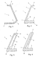
- Fig. 1 is denoted by 1 a soundproofing element according to the present invention, which is substantially C-shaped and opens to a sound source, not shown in the figures.
- the soundproofing element 1 in this case has a bearing surface 2, a rear surface 3 and a cover surface 4.
- the support surface 2 is in this case formed so that the leg forming it of the soundproofing element 1 has a length which projects beyond the articulation point 5 of the rear surface 3 to the top surface 4. Such a length of the bearing surface 2 is required for a secure state of the soundproofing element 1.
- the soundproofing element 1 is formed with a connecting web 6, which is arranged between the bearing surface 2 and the rear surface 3 in order to increase the overall stability of the soundproofing element 1.
- an opening 7 is shown, which Opening 7 is provided, for example, for the expiry of rainwater. If necessary, this opening 7 can also be used by animals as an escape route, and its clear width is sufficient to allow, for example, smaller animals, such as mice and the like, passage.
- the support surface 2 may also be formed on its underside with schematically indicated grooves 14 in order to ensure a drain of the rainwater.
- the top surface 4 is formed with a small shoulder 8, in which paragraph 8 is shown schematically, for example, a reflector or training in sound insulation of shell concrete, a grounding 15 can be used, which may be formed projecting on the back surface 3 to the visibility of the Ensure top edge of the soundproofing element 1 even at night.
- the top surface 4 may also be formed with a non-slip and / or reflective surface to improve the visibility of the surface at night.
- Fig. 2 is a cross section of a variant of the soundproofing element 1 of Fig. 1 represented, wherein the reference numerals of Fig. 1 as far as possible are maintained.
- the soundproofing element 1 is here in deviation from the illustration according to Fig. 1 formed with a respect to the top surface 4 and rear surface 3 thickened bearing surface 2.
- Such a thickened or a larger material thickness having support surface 2 ensures this particular, that inadvertent tilting or displacement of the soundproofing element 1 by pressure and suction loads is stopped by the train traffic.
- the total weight of the soundproofing element 1 is significantly increased by such a design, so that is ensured with such a design of the soundproofing element 1, that this safely and reliably without additional anchoring in the ground at the designated place even without a separately made for this foundation can be.
- a matching support element could be applied to the support surface 2 in order to ensure the necessary material thickness in the region of the foot or the bearing surface 2 of the soundproofing element 1.
- Fig. 2 is different from the representation of Fig. 1 the rear surface 3 is articulated directly to the bearing surface 2 and in the side facing the sound source side of the soundproofing element 1, the region of the connection between the rear surface 3 and support surface 2 with a particular running or curved hollow trough 16 is shown.
- Fig. 3 In the presentation of Fig. 3 are again the reference numerals of Fig. 1 maintained. at Fig. 3a are in the soundproofing element 1 of Fig. 1 on the inside facing the sound source, in particular the rear surface 3 with the end edge 13 of the top surface 4 aligned sound-absorbing insert 9 is inserted.
- a sound-absorbing insert 9 can in this case be a concrete material absorber, which is inseparably connected to the soundproofing element 1, for example by being embedded in concrete or else a subsequently attached sound-absorbing insert 9.
- Fig. 3b the soundproofing element 1 is shown in an embodiment in which the rear surface 3 and the absorbent insert 9 together form a cover surface 4 of the soundproofing element.
- the sound-absorbing insert 9 is in this case again formed of a concrete material absorber, whereupon the tread surface overall for the user no difference to an integrally formed cover surface 4, as in Fig. 3a is shown.
- the articulation of the rear surface 3 to the bottom surface 2 is here in accordance with the variant Fig. 3b shown that the rear surface 3 and its absorbent insert 9 are inclined to the bottom surface and in the direction of a sound source.
- Fig. 4a 4b respectively cross-sections through the end regions and in particular through two mutually different end regions of the soundproofing element 1 are shown.
- Appearances 10 are formed on the outside of the rear surface 3 of the soundproofing element 1 in the end regions facing the adjacent soundproofing elements 1, which appearances 10 are formed as recessed steps. These recessed steps 10 are in this case arranged in the respective end regions in different elevated positions, so that when arranging two soundproofing elements 1 next to one another a kind of staircase is made available, as described below in FIG Fig. 5 is apparent.
- protruding appearances 11 are formed on the inside of the soundproofing element 1, which are intended to enable a slight overcoming of the soundproofing elements 1 also from the side of the soundproofing element 1 facing the sound source.
- Such gigs 11 are for example for railway personnel, which performs maintenance on the tracks or cleaning personnel required and therefore can be easily formed as a metal bracket because such persons usually do not have any motor impairments.
- Fig. 5 is a soundproofing element 1 with greater Wandstär-ke the rear surface 3 and the top surface 4 in comparison to the formation of Fig. 1 represented, so that without an additional thickening of the support surface 2, the soundproofing element 1 has a sufficient weight to be secured against unintentional displacement.
- Fig. 6 is a plan view of two juxtaposed soundproofing elements 1 is shown, in which plan view can be seen inter alia that the gigs 11 are also arranged at different heights on adjacent end portions of soundproofing elements 1, also to the Train staff to allow easy leaving the interior or the sound source facing the area of a sound insulation system. Furthermore, this representation can be taken that for a safe and attractive combination of two adjacent soundproofing elements 1, the soundproofing elements 1 are provided on their adjacent to soundproofing elements side edges with projections 12 so that two adjacent soundproofing elements 1 comb with proper arrangement directly and thus neither a shift the sound protection elements 1 in the height direction still a gap between two soundproofing elements 1 is caused.
Landscapes
- Engineering & Computer Science (AREA)
- Aviation & Aerospace Engineering (AREA)
- Transportation (AREA)
- Mechanical Engineering (AREA)
- Architecture (AREA)
- Civil Engineering (AREA)
- Structural Engineering (AREA)
- Life Sciences & Earth Sciences (AREA)
- Sustainable Development (AREA)
- Devices Affording Protection Of Roads Or Walls For Sound Insulation (AREA)
- Railway Tracks (AREA)
Abstract
Bei einem Schallschutzsystem für Verkehrswege, insbesondere Schienenwege, umfassend eine Mehrzahl von im Wesentlichen C-förmigen sich zu einer Schallquelle öffnende, mit der Waagrechten einen spitzen Winkel einschließende miteinander verbindbare Schallschutzelemente (1), ist jedes Schallschutzelement (1) einstückig ausgebildet und ein eine Auflagerfläche (2) des Schallschutzelements (1) ausbildender Schenkel des Schallschutzelements (1) weist eine Längserstreckung auf, die einen von der Auflagerfläche (2) beabstandeten Anlenkpunkt (5) für eine gegebenenfalls die Materialstärke der Rückfläche (3) überragenden Deckfläche (4) des Schallschutzelements (1) überragt.In a soundproofing system for traffic routes, in particular railways, comprising a plurality of substantially C-shaped soundproofing elements (1) opening to a sound source and enclosing an acute angle with the horizontal, each soundproofing element (1) is integrally formed and one is a bearing surface (2) of the soundproofing element (1) forming leg of the soundproofing element (1) has a longitudinal extent, one of the support surface (2) spaced articulation point (5) for an optionally the material thickness of the rear surface (3) superior top surface (4) of the soundproofing element (1) dominates.
Description
Die vorliegende Erfindung bezieht sich auf ein Schallschutzsystem für Verkehrswege, insbesondere Schienenwege, umfassend eine Mehrzahl von im Wesentlichen C-förmigen sich zu einer Schallquelle öffnende, mit der Waagrechten einen spitzen Winkel einschließende miteinander verbindbare Schallschutzelemente.The present invention relates to a soundproofing system for traffic routes, in particular railways, comprising a plurality of substantially C-shaped soundproofing elements which open to a sound source and connect with the horizontal at an acute angle.
Schallschutzsysteme für Verkehrswege sind in unterschiedlichsten Ausführungen bekannt und werden insbesondere neben Autobahnen und Bahngeleisen in verbautem Gebiet oder städtischem Umfeld eingesetzt, um Anrainer vor unnötigen Lärmbelästigungen zu schützen. Derartige Schallschutzsysteme sind häufig konstruktiv aufwendige Bauwerke, um den von den Verkehrswegen emittierten Schall so vollständig wie möglich zu absorbieren und somit die Lärmbelästigung auf der verbauten Seite des Schallschutzsystems so gering wie möglich zu halten. Zur Erzielung dieses Effekts wurden bereits die unterschiedlichsten Systeme zum Einsatz gebracht, welche einerseits meist relativ hochbauend sind und andererseits aus den verschiedensten Materialien gefertigt sind, um sowohl einen ausreichenden Lärmschutz zur Verfügung zu stellen als auch ästhetischen Anforderungen zu genügen.Acoustic systems for traffic routes are known in a variety of versions and are used in particular in addition to highways and railway tracks in built-up area or urban environment to protect residents from unnecessary noise pollution. Such sound insulation systems are often structurally complex structures in order to absorb the sound emitted by the traffic routes as completely as possible and thus to keep the noise pollution on the installed side of the sound insulation system as low as possible. To achieve this effect, a variety of systems have already been used, which are on the one hand usually relatively high-building and on the other hand made of a variety of materials in order to provide both sufficient noise protection and to meet aesthetic requirements.
Bei dem in der
Aus der
Die vorliegende Erfindung zielt nun darauf ab, ein niedrigbauendes Schallschutzsystem für Verkehrswege, insbesondere für Schienenwege zur Verfügung zu stellen, welches einerseits den Schall nahezu ausschließlich reflektiert und andererseits schnell und zuverlässig errichtet werden kann, ohne dass aufwändige Arbeiten, wie beispielsweise Betonieren eines Fundaments oder dgl. erforderlich sind.The present invention now aims to provide a low-building noise control system for traffic routes, especially for railways available, which on the one hand reflects the sound almost exclusively and on the other hand can be built quickly and reliably, without elaborate work, such as concreting a foundation or the like . required are.
Zur Lösung dieser Aufgabe ist das erfindungsgemäße Schallschutzsystem im Wesentlichen dadurch gekennzeichnet, dass jedes Schallschutzelement einstückig ausgebildet ist und dass ein eine Auflagerfläche des Schallschutzelements ausbildender Schenkel des Schallschutzelements eine Längserstreckung aufweist, die einen von der Auflagerfläche beabstandeten Anlenkpunkt für eine gegebenenfalls die Materialstärke der Rückfläche überragenden Deckfläche des Schallschutzelements überragt. Indem einerseits jedes Schallschutzelement einstückig ausgebildet ist und andererseits ein eine Auflagefläche des Schallschutzelements ausbildender Schenkel des Schallschutzelements eine Längserstreckung aufweist, die einen von der Auflagerfläche beabstandeten Anlenkpunkt für eine gegebenenfalls die Materialstärke der Rückfläche überragenden Deckfläche des Schallschutzelements überragt, gelingt es, das Schallschutzelement einfach auf dem Boden im Bereich neben der zu erwartenden Schallquelle, wie beispielsweise neben einem Schienenweg aufzustellen, wo es aufgrund dieser spezifischen Konstruktion angeordnet werden kann, ohne dass eine weitere Festlegung am Untergrund erforderlich ist. Um ein Umkippen des Schallschutzelements neben der Schallquelle mit Sicherheit zu vermeiden, kann beispielsweise im Fall eines Schallschutzelements neben einem Schienenweg das Schallschutzelement im Bereich seiner Auflagerfläche bis zu einer bestimmten Tiefe in dem Gleisbett eingebettet werden und mit dem Schotter des Gleisbetts bedeckt werden, wodurch ein willkürliches Verrücken, insbesondere durch Druck- und Sogkräfte des Zugverkehrs mit Sicherheit hintangehalten wird. Weiterhin wird durch eine derartige Konstruktion auch ein Kippen des Elements entweder beabsichtigt oder unbeabsichtigt, insbesondere aufgrund des Gewichts des Gleisbetts hintangehalten.To solve this problem, the soundproofing system according to the invention is essentially characterized in that each soundproofing element is integrally formed and that a leg of the soundproofing element forming a bearing surface of the soundproofing element has a longitudinal extent, which projects beyond an articulation point spaced from the support surface for a cover surface of the soundproofing element that may project beyond the material thickness of the rear surface. By on the one hand each soundproofing element is integrally formed and on the other hand a support surface of the soundproofing element forming leg of the soundproofing element has a longitudinal extension, which projects beyond a spaced from the support surface articulation point for an optionally the material thickness of the rear surface superior top surface of the soundproofing element succeeds, the soundproofing element simply on the Ground in the area adjacent to the expected sound source, such as next to a rail track, where it can be arranged due to this specific construction, without further fixing to the ground is required. To avoid overturning of the soundproofing element next to the sound source with certainty, for example, in the case of a soundproofing element next to a railroad, the soundproofing element can be embedded in the area of its support surface to a certain depth in the track bed and covered with the ballast of the track bed, creating an arbitrary Displacement, especially by pressure and suction forces of the train traffic is withheld with certainty. Furthermore, such a construction also prevents tilting of the element either intentionally or unintentionally, in particular due to the weight of the track bed.
Durch die spezifische C-Form, welche sich in Richtung zur Schallquelle öffnet, wird weiterhin sichergestellt, dass der von der Lärmquelle, beispielsweise dem Schienenfahrzeug, insbesondere einer Eisenbahn emittierte Schall mit Sicherheit in das Gleisbett reflektiert wird, wo er in der Folge absorbiert wird. In diesem Zusammenhang ist zu berücksichtigen, dass die Quelle der Lärmbelästigung dieser Fahrzeuge im Bereich ihrer Räder liegt, welche durch Rollreibung auf dem Untergrund, beispielsweise den Schienen, für den größten Teil des Lärms, welchen derartige Fahrzeuge beim Fahren verursachen, verantwortlich sind, so dass es ausreichend ist, ein Schallschutzsystem zur Verfügung zu stellen, welches in der Höhe die Oberkante der jeweiligen Räder abschließt bzw. diese geringfügig überragt. Die beste Reflexion des emittierten Schalls wird hierbei dann erzielt, wenn der Anlenkpunkt für eine gegebenenfalls vorgegebene Deckfläche möglicht hohe der Schallquelle angeordnet ist. Mit einem derartigen niedrigbauenden Schallschutzelement kann weiterhin sichergestellt werden, dass einerseits die im Fahrzeug, insbesondere Schienenfahrzeug sitzenden Personen einen freien Ausblick auf die Umgebung haben und auch die hinter der Lärmschutzsystem beheimateten Anrainer nicht durch hohe Wände vor ihren Anwesen bzw. Wohnungen beeinträchtigt sind.The specific C-shape which opens in the direction of the sound source further ensures that the sound emitted by the noise source, for example the rail vehicle, in particular a railway, is safely reflected in the track bed, where it is absorbed in the sequence. In this context, it should be noted that the Source of noise pollution of these vehicles in the area of their wheels, which are due to rolling friction on the ground, for example, the rails, for the majority of the noise caused by such vehicles when driving, so that it is sufficient to have a soundproofing system available set, which closes in height the upper edge of the respective wheels or slightly surmounted. The best reflection of the emitted sound is achieved in this case when the articulation point for an optionally predetermined top surface is arranged as high as possible of the sound source. With such a low-building soundproofing element can continue to ensure that on the one hand sitting in the vehicle, especially rail vehicle people have a clear view of the environment and also behind the noise abatement residents are not affected by high walls in front of their property or apartments.
Unter einer "C-Form" des Schallschutzelements wird hierbei jede Form verstanden, welche einem C ähnlich ist, wie beispielsweise ein C mit gerader zur Schallquelle geneigter Rückfläche, mit und ohne Deckfläche eines C, d.h. auch eine geneigte L-Form ebenso wie Formen, deren Deckflächen parallel zur Grundfläche sind, deren Deckflächen mit der Grundfläche einen Winkel einschließen und solche, deren Längserstreckung von Grund- und Deckfläche gleich oder voneinander verschieden ist.Here, a "C-shape" of the soundproofing element is understood to mean any shape that is similar to a C, such as a C with a straight back surface inclined to the sound source, with and without a top surface of a C, i. Also, an inclined L-shape as well as shapes whose top surfaces are parallel to the base, whose top surfaces with the base include an angle and those whose longitudinal extent of the base and top surface are equal or different.
Um eine Sollbruchstelle des Schallschutzsystems auszuschließen und eine besonders lange Standzeit desselben zu gewährleisten, ist das Schallschutzsystem gemäß der Erfindung bevorzugt so weitergebildet, dass das Schallschutzelement mit einem mit dem die Auflagerfläche ausbildenden Schenkel einen stumpfen Winkel einschließenden und mit dem die Rückfläche bzw. -wand ausbildenden Schenkel einen spitzen Winkel einschließenden Verbindungssteg ausgebildet ist. Durch Vorsehen eines Verbindungsstegs zwischen der Auflagefläche und der Rückfläche des im Wesentlichen C-förmigen Schallschutzelements wird sichergestellt, dass ein unbeabsichtigtes Knicken des Schallschutzelements, insbesondere Abknicken desselben, im Bereich der Anlenkung zwischen Auflagerfläche und Rückfläche auch bei hohen Belastungen, wie beispielsweise einem unbeabsichtigten Druck von außen oder einer Belastung von oben mit Sicherheit ausgeschlossen werden kann.In order to exclude a predetermined breaking point of the sound insulation system and to ensure a particularly long service life of the same, the sound insulation system according to the invention is preferably developed so that the soundproofing element with a with the support surface forming leg one obtuse angle enclosing and formed with the back surface or wall forming legs an acute angle enclosing connecting web. By providing a connecting web between the support surface and the rear surface of the substantially C-shaped soundproofing element ensures that an unintentional buckling of the soundproofing element, in particular kinking thereof, in the region of the articulation between the support surface and back surface even at high loads, such as an unintentional pressure of outside or a load from above can be excluded with certainty.
Indem, wie dies einer Weiterbildung der Erfindung entspricht, das Schallschutzsystem so ausgebildet ist, dass im Bereich des Verbindungsstegs wenigstens eine, insbesondere eine Mehrzahl von Durchbrechungen vorgesehen ist, wird ein sicheres Ableiten von Regenwasser aus dem Bereich des Schienenwegs bzw. einer Fahrstraße, an welcher das Schallschutzelement angeordnet ist, gewährleistet, indem die Flüssigkeit von dem jeweiligen Verkehrsweg durch die Durchbrechungen in die Umgebung, sei es in ein Kanalnetz oder in Felder oder dgl. abgeleitet wird.By, as corresponds to a development of the invention, the soundproofing system is designed so that at least one, in particular a plurality of openings is provided in the region of the connecting web, a safe discharge of rainwater from the region of the rail track or a driveway, at which the soundproofing element is arranged, guaranteed by the liquid from the respective traffic route through the openings in the environment, whether in a sewer network or in fields or the like. Derived.
Um die Standfestigkeit der einzelnen Schallschutzelemente weiter zu erhöhen und insbesondere sicherzustellen, dass ein unbeabsichtigtes Kippen bzw. Verrücken derselben, mit Sicherheit hintangehalten ist, ist das erfindungsgemäße Schallschutzsystem so weitergebildet, dass der die Auflagefläche ausbildende Schenkel des Schallschutzelements eine größere Materialstärke als die weiteren Schenkel des Schallschutzelements aufweist. Hierbei ist es insbesondere bevorzugt, dass die Materialstärke der Auflagerfläche wenigstens das 1,5-fache, insbesondere wenigstens das 7-fache der weiteren Schenkel des Schallschutzelements aufweist. Durch eine derartige Konstruktion gelingt es, einen stabilen Fuß bzw. eine stabile Standfläche des Schallschutzelements zur Verfügung zu stellen, welche ein ausreichendes Eigengewicht aufweist, in einer Lagesicherung zur Verfügung zu stellen, welche den verschiedensten Belastungen sicher standhält und welche auch gewährleistet, dass auch bei Einwirken von großen Momenten, wie ein Aufprall eines Fahrzeugs oder Druck- und Sogkräfte während des Vorbeifahrens von Zügen oder Lastkraftwagen, ein unbeabsichtigtes Verschieben um große Strecken bzw. Zerstören des Schallschutzelements mit Sicherheit hintangehalten ist.In order to further increase the stability of the individual soundproofing elements and in particular to ensure that unintentional tilting or dislocation thereof is safely contained, the soundproofing system according to the invention is developed such that the leg of the soundproofing element forming the contact surface has a greater material thickness than the further legs of the soundproofing element Soundproofing element has. It is particularly preferred that the material thickness of the support surface at least 1.5 times, in particular at least 7 times the other leg of the soundproofing element. By such a construction, it is possible to provide a stable foot or a stable surface of the soundproofing element available, which has a sufficient weight to provide in a position assurance available that withstands a variety of loads safely and which also ensures that even at Exposure of large moments, such as a collision of a vehicle or pressure and suction forces during the passage of trains or trucks, unintentional displacement by long distances or destruction of the soundproofing element is certainly withheld.
Alternativ kann, wie dies ebenfalls einer Weiterbildung der vorliegenden Erfindung entspricht, der die Auflagerfläche ausbildende Schenkel des Schallschutzelements zur Aufnahme eines Auflagerelements ausgebildet sein. Bei einer derartigen Ausbildung kann beispielsweise der die Auflagerfläche ausbildende Schenkel des Schallschutzelements an seinem zur Schallquelle gewandten Ende geringfügig nach oben gebogen sein, in welchem Fall in die dadurch ausgebildete Vertiefung ein beschwerendes Element, wie beispielsweise ein Betonstein oder dgl. eingelegt werden kann. Mit einer derartigen Ausbildung können relativ leichtgewichtigte Schallschutzelemente nebeneinander angeordnet werden und in der Folge durch Einsetzen von beschwerenden Elementen gegen ein Verschieben bzw. Bewegen gesichert werden. Wenn weiterhin die Auflagerelemente in der Form der Auflagerfläche entsprechen, können auch einzelne Schallschutzelemente verbaut werden und es entsteht beim Zusammenfügen mehrerer Schallschutzelemente andererseits ein Schallschutzsystem, welche die gleiche Sicherheit des Systems wie "schwere" Elemente bieten. Selbstverständlich kann ein derartiges Auflagerelement auch so ausgebildet sein, dass die in dem Schallschutzelement vorgesehenen Durchtrittöffnungen für Regenwasser sich in dem Auflagerelement fortsetzen bzw. auch in diesem ausbildet sind. In gleicher Weise können beispielsweise Ausnehmungen in dem Auflagerelement vorgesehen sein, um Fluchtkanäle für kleine Tiere oder dgl. auszubilden.Alternatively, as also corresponds to a development of the present invention, the support surface forming the leg of the soundproofing element may be formed for receiving a support element. In such a configuration, for example, the leg of the soundproofing element forming the bearing surface may be bent slightly upward at its end facing the sound source, in which case a weighting element, such as a concrete block or the like, may be inserted into the depression formed thereby. With such a design relatively lightweight soundproofing elements can be arranged side by side and are secured in the sequence by inserting weighting elements against displacement or movement. If, furthermore, the support elements correspond in the shape of the support surface, it is also possible to install individual soundproofing elements and, on the other hand, when assembling several soundproofing elements, a soundproofing system is created which offers the same system security as "heavy" elements. Of course, such a support element may also be designed so that the passage openings provided in the soundproofing element for rainwater continue in the support element or are formed in this. In the same way, for example, recesses may be provided in the support element to form escape channels for small animals or the like.
Dadurch, dass die Deckfläche als gesonderter an die Rückflche des Schallschutzelements angelenkter Schenkel ausgebildet ist, gelingt es einerseits, die Oberkante des Schallschutzsystems noch näher an die Schallquelle heranzuführen und somit die gesamte Abschirmung zu verbessern. Bei verbesserter Abschirmung wird gleichzeitig sichergestellt, dass ein noch größerer Teil des emittierten Schalls in dem Boden, beispielsweise in das Gleisbett reflektiert und dort absorbiert wird. Weiterhin gelingt es mit einer derartigen Ausbildung, die Deckfläche als Auftrittsfläche für Fahrgäste, welche beispielsweise einen auf offener Strecke zu überquerenden Zug verlassen müssen, zu benutzen.The fact that the top surface is formed as a separate leg hinged to the rear surface of the soundproofing element makes it possible on the one hand to bring the top edge of the soundproofing system even closer to the sound source and thus to improve the overall shielding. At the same time, with improved shielding, it is ensured that an even greater part of the emitted sound is reflected in the ground, for example in the track bed, and absorbed there. Furthermore, with such a design, it is possible to use the top surface as a step surface for passengers who, for example, have to leave a train to be crossed on an open route.
Indem, wie dies einer Weiterbildung der vorliegenden Erfindung entspricht, der eine Deckfläche ausbildende Schenkel des Schallschutzelements als im Wesentlichen waagrechte Auftrittfläche ausgebildet ist, kann bei einem derartigen Schallschutzsystem auf das Bereitstellen von gesonderten Fluchtwegen verzichtet werden, da mit einer derartigen Variante das Schallschutzsystem per se leicht als "Fluchtweg" bzw. Flucht helfendes Element eingesetzt werden kann. Insbesondere wenn das Schallschutzsystem neben Bahngleisen angewandt wird, gelingt es mit einer derartigen Ausbildung beispielsweise, Leute direkt aus einem auf freier Strecke stehenden Zug zu evakuieren, da diese unmittelbar von dem Wagon auf die Oberkante bzw. Auftrittsfläche des Schallschutzelements auftreten können und somit nicht in das Gleisbett hinuntersteigen müssen, was insbesondere für ältere oder gehbehinderte Personen äußerst beschwerlich ist.By, as this corresponds to a development of the present invention, the top surface forming a leg of the soundproofing element is formed as a substantially horizontal tread, can be dispensed with the provision of separate escape routes in such a soundproofing system, since with such a variant, the soundproofing system per se easily can be used as an "escape route" or escape-helping element. In particular, when the sound insulation system is applied next to railroad tracks, it is possible with such a training, for example, to evacuate people directly from a standing train on the free stretch, as they can occur directly from the wagon to the top or surface of the soundproofing element and thus not in the Have to descend the track bed, which is extremely difficult especially for elderly or handicapped people.
Indem, wie dies einer Weiterbildung der Erfindung entspricht; die Deckfläche rutschfest unter der reflektierenden Oberfläche ausgebildet ist, wird ihre Einsatzmöglichkeit als Fluchtweg weiter verbessert und überdies auch die Möglichkeit geschaffen, dass in der Nacht zu überquerende Personen aus Zügen, die Oberkante und somit die Auftrittsfläche sicher erkennen können.By, as corresponds to a development of the invention; the top surface is formed non-slip under the reflective surface, its use as an escape route is further improved and also created the possibility that people to be traversed by trains at night, the top and thus the tread can safely recognize.
Indem das erfindungsgemäße Schallschutzsystem weiterhin so ausgebildet ist, dass der die Rückfläche des Schallschutzsystems ausbildende Schenkel mit wenigstens einem Auftritt versehen ist, kann weiterhin beim Evakuieren von Fahrzeugen nicht nur die Oberseite des Schallschutzelements als Auftritt verwendet werden, sondern auch von dem Schallschutzsystem leicht in das umgebende Gelände abgestiegen werden. Derartige Auftritte, wenn sie in das Schallschutzelement direkt eingelassen sind, stellen hierbei sicher, dass einerseits die Schall reflektierende Wirkung des Systems nicht verschlechtert wird und andererseits ein Evakuieren von Personen von innerhalb des Schallschutzsystems leicht und zuverlässig möglich wird, da das Übersteigen des Schallschutzsystems besonders einfach bewerkstelligt werden kann.Furthermore, by designing the soundproofing system according to the invention such that the leg forming the rear surface of the soundproofing system is provided with at least one step, not only the upper side of the soundproofing element can be used as an appearance when evacuating vehicles, but also easily from the soundproofing system into the surrounding one Terrain are descended. Such appearances, when directly embedded in the soundproofing element, ensure that, on the one hand, the sound-reflecting effect of the system is not impaired and, on the other hand, evacuation of persons from inside the soundproofing system is easily and reliably possible, since the soundproofing system is particularly simple can be accomplished.
Wenn, wie dies einer Weiterbildung der Erfindung entspricht, die Auftritt von benachbart angeordneten Schallschutzelementen in der Höhe zueinander versetzt angeordnet sind, wird im Wesentlichen eine Treppe für zu überquerende Personen oder eine Treppe für Personen, welche Zutritt zu dem Schallschutzsystem benötigen, um beispielsweise Gleisbauarbeiten vorzunehmen, zur Verfügung gestellt.If, as corresponds to a development of the invention, the appearance of adjacently arranged soundproofing elements are staggered in height to each other, a staircase for people to be crossed or a staircase for people who need access to the sound insulation system, for example, to make track construction work , made available.
Wenn, wie dies einer Weiterbildung der Erfindung entspricht, dass der wenigstens eine Auftritt des die Rückfläche des Schallschutzelements ausbildenden Schenkels als in eine von der Schallquelle abgewandte Seite Rückfläche eingesenkte Stufe ausgebildet ist, ist das Verlassen von beispielsweise auf freier Strecke stehenden Züge auch für Kinder oder ältere Personen ohne zusätzliche Hilfemaßnahmen einfach möglich, indem sie von dem Zug direkt auf die Oberkante des Schallschutzelements steigen und von diesem über die in der Rückfläche des Schallschutzelements ausgebildeten Stufen das System nach außen verlassen.If, as this corresponds to a development of the invention, that the at least one appearance of the rear surface of the soundproofing element forming leg is formed as in a side facing away from the sound source side rear surface level formed, leaving from, for example, standing on the free train trains for children or Elderly persons without additional assistance measures easily possible by rising from the train directly on the upper edge of the soundproofing element and leave from this over the formed in the rear surface of the soundproofing elements the system to the outside.
In diesem Zusammenhang muss festgehalten werden, dass eine derartige Ausbildung des Schallschutzelements nur dadurch möglich wird, dass das Schallschutzelement insgesamt niedrigbauend ist. So weist es beispielsweise im Fall des Einsatzes an Eisenbahnen eine Höhe über Schienenkante von etwa 30 cm bis 1 m, insbesondere 55 cm bis 76 cm auf, wodurch ein Auftreten aus einem Zug auf die obere Deckfläche bzw. auf den Auftritt des C-förmigen Schallschutzelements problemlos ermöglicht wird. Gleichzeitig wird mit einer derartigen Höhe eines Schallschutzsystems sichergestellt, dass die hauptsächlich Lärm verursachenden Elemente eines Zugs, nämlich die Räder von dem Schallschutzsystem vollständig übergriffen sind, so dass nicht nur ein effektives Reflektieren des Schalls in das Gleichbett gewährleistet wird, sondern gleichzeitig ein formschönes, sicheres und einfach zu versetzendes Schallschutzsystem zur Verfügung gestellt wird.In this context, it must be noted that such a design of the soundproofing element is only possible because the soundproofing element is low overall construction. Thus, for example, in the case of use on railways, it has a height above the rail edge of about 30 cm to 1 m, in particular 55 cm to 76 cm, whereby an occurrence of a train on the upper deck surface or on the appearance of the C-shaped soundproofing element is easily possible. At the same time it is ensured with such a height of a sound insulation system, that the main noise-causing elements of a train, namely the wheels are completely overlapped by the sound insulation system, so that not only an effective reflection of the sound is ensured in the same bed, but at the same time a shapely, safe and easily deployable sound insulation system is provided.
Um auch beispielsweise dem Personal, welches am dem Fahrweg, insbesondere an dem Schienenweg Ausbesserungsarbeiten vornimmt, das Verlassen des Schallschutzsystems sicher und zuverlässig zu ermöglichen, ist gemäß einer Weiterbildung der Erfindung das System so ausgebildet, dass der wenigstens eine Auftritt des die Rückfläche des Schallschutzelements ausbildenden Schenkels als ein von einer der Schallquelle zugewandten Seite der Rückfläche vorragender Auftritt ausgebildet ist. Derartige Auftritte sind hierbei so ausgebildet, dass Arbeiten an der Gleisanlage, wie beispielsweise das Schneeräumen ohne Beeinträchtigung möglich sind.In order, for example, the staff, which carries out repair work on the track, especially on the railway, leaving the sound insulation system safely and reliably to allow, according to an embodiment of the invention, the system is designed so that the at least one appearance of the rear surface of the soundproofing element forming leg is formed as a projecting from one of the sound source side of the rear surface projecting appearance. Such appearances are in this case designed so that work on the track system, such as snow removal without impairment are possible.
Um eine möglichst vollständige Reflexion des Schalls in das Boden- bzw. Erdmaterial oder das Gleisbett im Bereich der Schallquelle zu gewährleisten, ist gemäß einer Weiterbildung der Erfindung das Schallschutzelement so ausgebildet, dass die Rückfläche wenigstens in ihrem Fußpunkt zur Lärmquelle geneigt ausgebildet ist. Durch eine derartige Neigung wird sichergestellt, dass der Schall in dem Bodenbereich reflektiert wird. Es ist in diesem Zusammenhang jedoch möglich, dass zumindest Einzelbereiche der Rückfläche auch senkrecht bzw. mit einer von der Neigung im Fußpunkt unterschiedlichen Neigung ausgebildet sind.In order to ensure the most complete reflection of the sound in the soil or earth material or the track bed in the area of the sound source, according to a development of the invention, the soundproofing element is formed so that the rear surface is inclined at least at its base to the noise source. Such an inclination ensures that the sound is reflected in the floor area. However, it is possible in this context that at least individual areas of the rear surface are also formed vertically or with a different inclination in the base of the inclination.
Für eine noch weitere Verringerung der nach außerhalb eines Schallschutzelements dringenden Geräuschbelästigung ist gemäß einer Weiterbildung der Erfindung das Schallschutzsystem so ausgebildet, dass das Schallschutzelement an der der Schallquelle zugewandten Seite eine Schall absorbierende Einlage aufweist. Durch Vorsehen derartiger Einlagen wird wenigstens ein Teil des Schalls direkt an dem Schallschutzelement absorbiert und nur ein Teil in beispielsweise das Gleisbett oder direkt in den Verkehrsweg reflektiert, so dass von dem Gleisbett bzw. dem Verkehrsweg nur mehr eine geringere Intensität des Schalls absorbiert werden muss.For an even further reduction of noise pollution outside of a soundproofing element, according to an embodiment of the invention, the soundproofing system is designed so that the soundproofing element has a sound-absorbing insert on the side facing the sound source. By providing such deposits, at least a portion of the sound is absorbed directly to the soundproofing element and only a part reflected in, for example, the trackbed or directly into the traffic route, so that only a lower intensity of the sound must be absorbed by the trackbed or the traffic route.
Um insbesondere eines ausreichende Standfestigkeit des Schallschutzsystems ohne weiteres Vorsehen eines Fundaments zu ermöglichen, ist gemäß einer Weiterbildung der Erfindung jedes Schallschutzelement aus Faserbeton, insbesondere Glasfaserbeton oder Stahlbeton ausgebildet. Insbesondere der Einsatz von Faserbeton, wie Glasfaserbeton garantiert lange Standzeiten bei gleichzeitig ästhetischem Aussehen und garantiert, dass beispielsweise ein Verschieben der einzelnen Schallschutzelemente aufgrund von mechanischen Beanspruchungen mit Sicherheit hintangehalten wird.In particular, to allow a sufficient stability of the sound insulation system without further provision of a foundation, according to a development of the invention, each soundproofing element made of fiber concrete, in particular glass fiber reinforced concrete or reinforced concrete is formed. In particular, the use of fiber concrete, such as fiberglass concrete guarantees long service life at the same time aesthetic appearance and guarantees that, for example, a shift of the individual soundproofing elements due to mechanical stresses is certainly withheld.
Um die Gefahr des Verschiebens von Einzelelementen noch weiter abzusenken, ist gemäß einer Weiterbildung der Erfindung das Schallschutzsystem so ausgebildet, dass die Schallschutzelemente an ihren zu benachbarten Schallschutzelementen gewandten Seitenkanten mit Vorsprüngen oder Materialverjüngungen ausgebildet sind, die in komplementäre Vorsprünge bzw. Materialverjüngungen benachbarter Schalschutzelemente eingreifen bzw. kämmen. Indem die Schallschutzelemente an ihren zum benachbarten Schallschutzelementen gewandten Seitenkanten mit Vorsprüngen und/oder Materialverjüngungen ausgebildet sind, die in komplementäre Vorsprünge bzw. Materialverjüngungen benachbarter Schallschutzelemente eingreifen bzw. mit diesen Kämmen, wird ein bündiges Ineinanderfügen der einzelnen Schallschutzelemente sichergestellt, wodurch nicht nur die Ästhetik des gesamten Schallschutzsystems erhöht wird, sondern auch dessen Sicherheit weiter verbessert werden kann.In order to further reduce the risk of shifting individual elements, according to a development of the invention, the soundproofing system is designed such that the soundproofing elements are formed with projections or material tapers on their side edges facing adjacent soundproofing elements, which engage in complementary projections or material tapers of adjacent soundproofing elements . comb. By the soundproofing elements are formed on their side edges facing the adjacent soundproofing elements with projections and / or material tapers, which engage in complementary projections or material tapers of adjacent soundproofing elements or with these combs, a flush nesting of the individual soundproofing elements is ensured, whereby not only the aesthetics of the entire sound insulation system is increased, but also its safety can be further improved.
Die Erfindung wird nachfolgend anhand von in der Zeichnung dargestellten Ausführungsbeispielen näher erläutert. In dieser zeigen:
-
Fig. 1 einen Querschnitt durch ein Schallschutzelement gemäß der Erfindung; -
Fig. 2 einen Querschnitt durch eine Abwandlung des Schallschutzelements vonFig. 1 ; -
Fig. 3a einen Querschnitt durch ein Schallschutzelement gemäß der Erfindung mit absorbierenden Einlagen; -
Fig. 3b einen Querschnitt durch eine abgewandelte Ausbildung des Schallschutzelements gemäß der Erfindung; -
Fig. 4a einen Querschnitt durch ein Schallschutzelement gemäß der Erfindung mit darin festgelegten bzw. ausgebildeten Auftritten bzw. stufenartigen Elementen; -
Fig. 4b einen analogen Schnitt wieFig. 4a , jedoch mit an anderen Positionen angeordneten Stufen bzw. Auftritten; -
Fig. 5 ein Querschnitt durch ein eine größere Wandstärke aufweisendes Schallschutzelement gemäß der Erfindung; und -
Fig. 6 eine Draufsicht auf zwei miteinander verbundene Schallschutzelemente gemäß der Erfindung.
-
Fig. 1 a cross section through a soundproofing element according to the invention; -
Fig. 2 a cross-section through a modification of the soundproofing element ofFig. 1 ; -
Fig. 3a a cross section through a soundproofing element according to the invention with absorbent inserts; -
Fig. 3b a cross-section through a modified embodiment of the soundproofing element according to the invention; -
Fig. 4a a cross-section through a soundproofing element according to the invention with defined therein or formed appearances or step-like elements; -
Fig. 4b an analogue cut likeFig. 4a but with steps or positions arranged at other positions; -
Fig. 5 a cross section through a greater wall thickness exhibiting soundproofing element according to the invention; and -
Fig. 6 a plan view of two interconnected soundproofing elements according to the invention.
In
Schließlich ist in der Darstellung von
Gegebenenfalls kann die Deckfläche 4 auch mit einer rutschfesten und/oder reflektierenden Oberfläche ausgebildet sein, damit die Sichtbarkeit der Oberfläche in der Nacht verbessert wird.Optionally, the
In
Das Schallschutzelement 1 ist hierbei in Abweichung von der Darstellung gemäß
Bei der Darstellung von
In
In
Im Falle eines Nothalts von beispielsweise einem Eisenbahnzug kann mit einer derartigen Ausbildung des Schallschutzsystems und insbesondere von zwei benachbarten Schallschutzelementen 1 beispielsweise ein Fahrgast den Zug dadurch verlassen, dass er aus einer Türe des Zugs unmittelbar auf die Deckfläche 4 des Schallschutzelements 1 steigt, welche Deckfläche 4 im Wesentlichen auf gleicher Höhe wie die Türe des Zugs ist und von dieser auch nur einige wenige Zentimeter beabstandet ist. In der Folge kann der Fahrgast durch Benützung der Stufen 10 an der Außenseite der Rückfläche 3 des Schallschutzelements 1 nach Art einer Leiter am Schallschutzelement 1 hinuntersteigen und beispielsweise außerhalb des Schallschutzelements die Bahntrasse betreten. Eine derartige Ausbildung hat insbesondere den Vorteil, dass die extrem hohe Stufe, welche beim Verlassen des Zugs zwischen der untersten vorgesehenen Treppe und der Bahntrasse üblicherweise vorliegt, auf diese Weise vermieden werden kann.In the case of an emergency stop of, for example, a railway train, with such a design of the soundproofing system and in particular of two
In
In
Claims (18)
Priority Applications (1)
| Application Number | Priority Date | Filing Date | Title |
|---|---|---|---|
| PL13004380T PL2811074T3 (en) | 2012-09-18 | 2013-09-09 | Noise reduction system for traffic routes |
Applications Claiming Priority (1)
| Application Number | Priority Date | Filing Date | Title |
|---|---|---|---|
| ATGM366/2012U AT13207U1 (en) | 2012-09-18 | 2012-09-18 | Sound insulation system for traffic routes |
Publications (3)
| Publication Number | Publication Date |
|---|---|
| EP2811074A2 true EP2811074A2 (en) | 2014-12-10 |
| EP2811074A3 EP2811074A3 (en) | 2014-12-17 |
| EP2811074B1 EP2811074B1 (en) | 2016-11-09 |
Family
ID=48875310
Family Applications (1)
| Application Number | Title | Priority Date | Filing Date |
|---|---|---|---|
| EP13004380.5A Not-in-force EP2811074B1 (en) | 2012-09-18 | 2013-09-09 | Noise reduction system for traffic routes |
Country Status (4)
| Country | Link |
|---|---|
| EP (1) | EP2811074B1 (en) |
| AT (1) | AT13207U1 (en) |
| ES (1) | ES2611964T3 (en) |
| PL (1) | PL2811074T3 (en) |
Cited By (1)
| Publication number | Priority date | Publication date | Assignee | Title |
|---|---|---|---|---|
| CN108797409A (en) * | 2018-08-03 | 2018-11-13 | 黄旭东 | A kind of special sound barrier of high ferro station main track and installation method |
Citations (2)
| Publication number | Priority date | Publication date | Assignee | Title |
|---|---|---|---|---|
| DE3934489A1 (en) | 1987-07-06 | 1991-04-25 | Hans Ulrich Ing Terkl | Sound barrier alongside railway track |
| AT501910B1 (en) | 2004-07-23 | 2006-12-15 | Orange Architekten Ges B R Tsc | SOUNDPROOF SYSTEM FOR TRAFFIC ROUTES |
Family Cites Families (4)
| Publication number | Priority date | Publication date | Assignee | Title |
|---|---|---|---|---|
| BE1005880A6 (en) * | 1993-06-30 | 1994-02-22 | Ronveaux E Ets Sa | NOISE SCREEN FOR TRAFFIC LANES. |
| DE19517110A1 (en) * | 1995-05-10 | 1996-11-28 | Heilit & Woerner Bau Ag | Sound absorber construction for solid roads |
| AT408999B (en) * | 1995-06-08 | 2002-04-25 | Porr Allg Bauges | Platform |
| SE0302642L (en) * | 2003-10-06 | 2004-10-19 | Bloc Internat Ab Z | Noise protection |
-
2012
- 2012-09-18 AT ATGM366/2012U patent/AT13207U1/en not_active IP Right Cessation
-
2013
- 2013-09-09 ES ES13004380.5T patent/ES2611964T3/en active Active
- 2013-09-09 EP EP13004380.5A patent/EP2811074B1/en not_active Not-in-force
- 2013-09-09 PL PL13004380T patent/PL2811074T3/en unknown
Patent Citations (2)
| Publication number | Priority date | Publication date | Assignee | Title |
|---|---|---|---|---|
| DE3934489A1 (en) | 1987-07-06 | 1991-04-25 | Hans Ulrich Ing Terkl | Sound barrier alongside railway track |
| AT501910B1 (en) | 2004-07-23 | 2006-12-15 | Orange Architekten Ges B R Tsc | SOUNDPROOF SYSTEM FOR TRAFFIC ROUTES |
Cited By (1)
| Publication number | Priority date | Publication date | Assignee | Title |
|---|---|---|---|---|
| CN108797409A (en) * | 2018-08-03 | 2018-11-13 | 黄旭东 | A kind of special sound barrier of high ferro station main track and installation method |
Also Published As
| Publication number | Publication date |
|---|---|
| EP2811074A3 (en) | 2014-12-17 |
| PL2811074T3 (en) | 2017-04-28 |
| ES2611964T3 (en) | 2017-05-11 |
| AT13207U1 (en) | 2013-08-15 |
| EP2811074B1 (en) | 2016-11-09 |
Similar Documents
| Publication | Publication Date | Title |
|---|---|---|
| EP0014172A1 (en) | Protective wall for road-vehicle guidance and for shielding residents from traffic noise | |
| DE202011104387U1 (en) | Protective wall made of individual protective wall elements to secure traffic routes | |
| EP0014171A1 (en) | Safety guide for road traffic | |
| AT508575B1 (en) | PROTECTION DEVICE | |
| EP2210978A2 (en) | Protective wall for sleeper platforms | |
| EP0016353A1 (en) | Set of building parts for the construction of three-dimensional structures | |
| EP2205797A1 (en) | Vehicle restraint system | |
| DE3929819A1 (en) | Barrier for building site - has steel panel bolted to steel posts welded to base plates | |
| EP2811074B1 (en) | Noise reduction system for traffic routes | |
| DE202012008924U1 (en) | Sound insulation system for traffic routes | |
| DE4219572A1 (en) | Travelling gear for crash barrier - has lifting device with longitudinal axis, formed as rotary axis for travelling gear | |
| DE4135445C2 (en) | Platform edge | |
| EP1206599B1 (en) | Damping section for channel rails | |
| DE4113508A1 (en) | Vehicle boarding step for bus stops - has upper section in vertical direction, made of elastic rubber or plastics | |
| EP0534058A1 (en) | Structural assembly for playgrounds | |
| DE202009008366U1 (en) | Railway track, in particular for a tunnel or bridge area | |
| WO2009124519A1 (en) | Vehicle restraint system | |
| DE102008026661B4 (en) | Verkehrsleitwand | |
| DE8532773U1 (en) | Large-format shaped concrete block for the erection of vertical, plantable visible and / or soundproof walls | |
| EP1502998A2 (en) | Draining element and use of a draining element | |
| DE102017111298A1 (en) | Rail arrangement for rail vehicles with flange wheels | |
| DE202017103535U1 (en) | Support structure and access ramp | |
| DE3229460A1 (en) | WALL CONSTRUCTED FROM PRE-MADE AND ASSEMBLABLE PROFILE COMPONENTS, IN PARTICULAR FOR NOISE AND VISUAL PROTECTION | |
| AT512845B1 (en) | Support part for a step of a footpath in the outdoor area | |
| EP2184213B1 (en) | Railway vehicle with a driver's compartment with a foot plate that is at least partially deformable |
Legal Events
| Date | Code | Title | Description |
|---|---|---|---|
| PUAL | Search report despatched |
Free format text: ORIGINAL CODE: 0009013 |
|
| PUAI | Public reference made under article 153(3) epc to a published international application that has entered the european phase |
Free format text: ORIGINAL CODE: 0009012 |
|
| 17P | Request for examination filed |
Effective date: 20130909 |
|
| AK | Designated contracting states |
Kind code of ref document: A2 Designated state(s): AL AT BE BG CH CY CZ DE DK EE ES FI FR GB GR HR HU IE IS IT LI LT LU LV MC MK MT NL NO PL PT RO RS SE SI SK SM TR |
|
| AX | Request for extension of the european patent |
Extension state: BA ME |
|
| AK | Designated contracting states |
Kind code of ref document: A3 Designated state(s): AL AT BE BG CH CY CZ DE DK EE ES FI FR GB GR HR HU IE IS IT LI LT LU LV MC MK MT NL NO PL PT RO RS SE SI SK SM TR |
|
| AX | Request for extension of the european patent |
Extension state: BA ME |
|
| RIC1 | Information provided on ipc code assigned before grant |
Ipc: E01F 8/00 20060101AFI20141110BHEP |
|
| R17P | Request for examination filed (corrected) |
Effective date: 20150616 |
|
| RBV | Designated contracting states (corrected) |
Designated state(s): AL AT BE BG CH CY CZ DE DK EE ES FI FR GB GR HR HU IE IS IT LI LT LU LV MC MK MT NL NO PL PT RO RS SE SI SK SM TR |
|
| GRAP | Despatch of communication of intention to grant a patent |
Free format text: ORIGINAL CODE: EPIDOSNIGR1 |
|
| INTG | Intention to grant announced |
Effective date: 20160414 |
|
| GRAS | Grant fee paid |
Free format text: ORIGINAL CODE: EPIDOSNIGR3 |
|
| GRAJ | Information related to disapproval of communication of intention to grant by the applicant or resumption of examination proceedings by the epo deleted |
Free format text: ORIGINAL CODE: EPIDOSDIGR1 |
|
| GRAL | Information related to payment of fee for publishing/printing deleted |
Free format text: ORIGINAL CODE: EPIDOSDIGR3 |
|
| GRAP | Despatch of communication of intention to grant a patent |
Free format text: ORIGINAL CODE: EPIDOSNIGR1 |
|
| INTC | Intention to grant announced (deleted) | ||
| INTG | Intention to grant announced |
Effective date: 20160902 |
|
| GRAA | (expected) grant |
Free format text: ORIGINAL CODE: 0009210 |
|
| AK | Designated contracting states |
Kind code of ref document: B1 Designated state(s): AL AT BE BG CH CY CZ DE DK EE ES FI FR GB GR HR HU IE IS IT LI LT LU LV MC MK MT NL NO PL PT RO RS SE SI SK SM TR |
|
| REG | Reference to a national code |
Ref country code: GB Ref legal event code: FG4D Free format text: NOT ENGLISH |
|
| REG | Reference to a national code |
Ref country code: AT Ref legal event code: REF Ref document number: 844048 Country of ref document: AT Kind code of ref document: T Effective date: 20161115 Ref country code: CH Ref legal event code: EP |
|
| REG | Reference to a national code |
Ref country code: IE Ref legal event code: FG4D Free format text: LANGUAGE OF EP DOCUMENT: GERMAN |
|
| REG | Reference to a national code |
Ref country code: DE Ref legal event code: R096 Ref document number: 502013005258 Country of ref document: DE |
|
| REG | Reference to a national code |
Ref country code: CH Ref legal event code: NV Representative=s name: MICHELI AND CIE SA, CH |
|
| REG | Reference to a national code |
Ref country code: NL Ref legal event code: FP |
|
| REG | Reference to a national code |
Ref country code: SE Ref legal event code: TRGR |
|
| PG25 | Lapsed in a contracting state [announced via postgrant information from national office to epo] |
Ref country code: LV Free format text: LAPSE BECAUSE OF FAILURE TO SUBMIT A TRANSLATION OF THE DESCRIPTION OR TO PAY THE FEE WITHIN THE PRESCRIBED TIME-LIMIT Effective date: 20161109 |
|
| REG | Reference to a national code |
Ref country code: LT Ref legal event code: MG4D |
|
| PG25 | Lapsed in a contracting state [announced via postgrant information from national office to epo] |
Ref country code: GR Free format text: LAPSE BECAUSE OF FAILURE TO SUBMIT A TRANSLATION OF THE DESCRIPTION OR TO PAY THE FEE WITHIN THE PRESCRIBED TIME-LIMIT Effective date: 20170210 Ref country code: LT Free format text: LAPSE BECAUSE OF FAILURE TO SUBMIT A TRANSLATION OF THE DESCRIPTION OR TO PAY THE FEE WITHIN THE PRESCRIBED TIME-LIMIT Effective date: 20161109 Ref country code: NO Free format text: LAPSE BECAUSE OF FAILURE TO SUBMIT A TRANSLATION OF THE DESCRIPTION OR TO PAY THE FEE WITHIN THE PRESCRIBED TIME-LIMIT Effective date: 20170209 |
|
| REG | Reference to a national code |
Ref country code: ES Ref legal event code: FG2A Ref document number: 2611964 Country of ref document: ES Kind code of ref document: T3 Effective date: 20170511 |
|
| PG25 | Lapsed in a contracting state [announced via postgrant information from national office to epo] |
Ref country code: FI Free format text: LAPSE BECAUSE OF FAILURE TO SUBMIT A TRANSLATION OF THE DESCRIPTION OR TO PAY THE FEE WITHIN THE PRESCRIBED TIME-LIMIT Effective date: 20161109 Ref country code: RS Free format text: LAPSE BECAUSE OF FAILURE TO SUBMIT A TRANSLATION OF THE DESCRIPTION OR TO PAY THE FEE WITHIN THE PRESCRIBED TIME-LIMIT Effective date: 20161109 Ref country code: HR Free format text: LAPSE BECAUSE OF FAILURE TO SUBMIT A TRANSLATION OF THE DESCRIPTION OR TO PAY THE FEE WITHIN THE PRESCRIBED TIME-LIMIT Effective date: 20161109 Ref country code: PT Free format text: LAPSE BECAUSE OF FAILURE TO SUBMIT A TRANSLATION OF THE DESCRIPTION OR TO PAY THE FEE WITHIN THE PRESCRIBED TIME-LIMIT Effective date: 20170309 Ref country code: IS Free format text: LAPSE BECAUSE OF FAILURE TO SUBMIT A TRANSLATION OF THE DESCRIPTION OR TO PAY THE FEE WITHIN THE PRESCRIBED TIME-LIMIT Effective date: 20170309 |
|
| REG | Reference to a national code |
Ref country code: CH Ref legal event code: PK Free format text: DAS PRIORITAETSAKTENZEICHEN WURDE BERICHTIGT: AT 3662012 U / 18.09.2012 |
|
| PG25 | Lapsed in a contracting state [announced via postgrant information from national office to epo] |
Ref country code: RO Free format text: LAPSE BECAUSE OF FAILURE TO SUBMIT A TRANSLATION OF THE DESCRIPTION OR TO PAY THE FEE WITHIN THE PRESCRIBED TIME-LIMIT Effective date: 20161109 Ref country code: CZ Free format text: LAPSE BECAUSE OF FAILURE TO SUBMIT A TRANSLATION OF THE DESCRIPTION OR TO PAY THE FEE WITHIN THE PRESCRIBED TIME-LIMIT Effective date: 20161109 Ref country code: SK Free format text: LAPSE BECAUSE OF FAILURE TO SUBMIT A TRANSLATION OF THE DESCRIPTION OR TO PAY THE FEE WITHIN THE PRESCRIBED TIME-LIMIT Effective date: 20161109 Ref country code: DK Free format text: LAPSE BECAUSE OF FAILURE TO SUBMIT A TRANSLATION OF THE DESCRIPTION OR TO PAY THE FEE WITHIN THE PRESCRIBED TIME-LIMIT Effective date: 20161109 Ref country code: EE Free format text: LAPSE BECAUSE OF FAILURE TO SUBMIT A TRANSLATION OF THE DESCRIPTION OR TO PAY THE FEE WITHIN THE PRESCRIBED TIME-LIMIT Effective date: 20161109 |
|
| REG | Reference to a national code |
Ref country code: DE Ref legal event code: R097 Ref document number: 502013005258 Country of ref document: DE |
|
| PG25 | Lapsed in a contracting state [announced via postgrant information from national office to epo] |
Ref country code: BG Free format text: LAPSE BECAUSE OF FAILURE TO SUBMIT A TRANSLATION OF THE DESCRIPTION OR TO PAY THE FEE WITHIN THE PRESCRIBED TIME-LIMIT Effective date: 20170209 Ref country code: IT Free format text: LAPSE BECAUSE OF FAILURE TO SUBMIT A TRANSLATION OF THE DESCRIPTION OR TO PAY THE FEE WITHIN THE PRESCRIBED TIME-LIMIT Effective date: 20161109 Ref country code: SM Free format text: LAPSE BECAUSE OF FAILURE TO SUBMIT A TRANSLATION OF THE DESCRIPTION OR TO PAY THE FEE WITHIN THE PRESCRIBED TIME-LIMIT Effective date: 20161109 |
|
| REG | Reference to a national code |
Ref country code: FR Ref legal event code: PLFP Year of fee payment: 5 |
|
| PLBE | No opposition filed within time limit |
Free format text: ORIGINAL CODE: 0009261 |
|
| STAA | Information on the status of an ep patent application or granted ep patent |
Free format text: STATUS: NO OPPOSITION FILED WITHIN TIME LIMIT |
|
| 26N | No opposition filed |
Effective date: 20170810 |
|
| PG25 | Lapsed in a contracting state [announced via postgrant information from national office to epo] |
Ref country code: SI Free format text: LAPSE BECAUSE OF FAILURE TO SUBMIT A TRANSLATION OF THE DESCRIPTION OR TO PAY THE FEE WITHIN THE PRESCRIBED TIME-LIMIT Effective date: 20161109 |
|
| PG25 | Lapsed in a contracting state [announced via postgrant information from national office to epo] |
Ref country code: MC Free format text: LAPSE BECAUSE OF FAILURE TO SUBMIT A TRANSLATION OF THE DESCRIPTION OR TO PAY THE FEE WITHIN THE PRESCRIBED TIME-LIMIT Effective date: 20161109 |
|
| REG | Reference to a national code |
Ref country code: IE Ref legal event code: MM4A |
|
| REG | Reference to a national code |
Ref country code: BE Ref legal event code: MM Effective date: 20170930 |
|
| PG25 | Lapsed in a contracting state [announced via postgrant information from national office to epo] |
Ref country code: LU Free format text: LAPSE BECAUSE OF NON-PAYMENT OF DUE FEES Effective date: 20170909 |
|
| PG25 | Lapsed in a contracting state [announced via postgrant information from national office to epo] |
Ref country code: IE Free format text: LAPSE BECAUSE OF NON-PAYMENT OF DUE FEES Effective date: 20170909 |
|
| REG | Reference to a national code |
Ref country code: FR Ref legal event code: PLFP Year of fee payment: 6 |
|
| PG25 | Lapsed in a contracting state [announced via postgrant information from national office to epo] |
Ref country code: BE Free format text: LAPSE BECAUSE OF NON-PAYMENT OF DUE FEES Effective date: 20170930 |
|
| PG25 | Lapsed in a contracting state [announced via postgrant information from national office to epo] |
Ref country code: MT Free format text: LAPSE BECAUSE OF FAILURE TO SUBMIT A TRANSLATION OF THE DESCRIPTION OR TO PAY THE FEE WITHIN THE PRESCRIBED TIME-LIMIT Effective date: 20161109 |
|
| PG25 | Lapsed in a contracting state [announced via postgrant information from national office to epo] |
Ref country code: HU Free format text: LAPSE BECAUSE OF FAILURE TO SUBMIT A TRANSLATION OF THE DESCRIPTION OR TO PAY THE FEE WITHIN THE PRESCRIBED TIME-LIMIT; INVALID AB INITIO Effective date: 20130909 |
|
| PG25 | Lapsed in a contracting state [announced via postgrant information from national office to epo] |
Ref country code: CY Free format text: LAPSE BECAUSE OF FAILURE TO SUBMIT A TRANSLATION OF THE DESCRIPTION OR TO PAY THE FEE WITHIN THE PRESCRIBED TIME-LIMIT Effective date: 20161109 |
|
| PG25 | Lapsed in a contracting state [announced via postgrant information from national office to epo] |
Ref country code: MK Free format text: LAPSE BECAUSE OF FAILURE TO SUBMIT A TRANSLATION OF THE DESCRIPTION OR TO PAY THE FEE WITHIN THE PRESCRIBED TIME-LIMIT Effective date: 20161109 |
|
| PG25 | Lapsed in a contracting state [announced via postgrant information from national office to epo] |
Ref country code: TR Free format text: LAPSE BECAUSE OF FAILURE TO SUBMIT A TRANSLATION OF THE DESCRIPTION OR TO PAY THE FEE WITHIN THE PRESCRIBED TIME-LIMIT Effective date: 20161109 |
|
| PG25 | Lapsed in a contracting state [announced via postgrant information from national office to epo] |
Ref country code: AL Free format text: LAPSE BECAUSE OF FAILURE TO SUBMIT A TRANSLATION OF THE DESCRIPTION OR TO PAY THE FEE WITHIN THE PRESCRIBED TIME-LIMIT Effective date: 20161109 |
|
| PGFP | Annual fee paid to national office [announced via postgrant information from national office to epo] |
Ref country code: NL Payment date: 20200824 Year of fee payment: 8 |
|
| PGFP | Annual fee paid to national office [announced via postgrant information from national office to epo] |
Ref country code: FR Payment date: 20200820 Year of fee payment: 8 Ref country code: GB Payment date: 20200824 Year of fee payment: 8 |
|
| PGFP | Annual fee paid to national office [announced via postgrant information from national office to epo] |
Ref country code: PL Payment date: 20200728 Year of fee payment: 8 Ref country code: SE Payment date: 20200824 Year of fee payment: 8 |
|
| PGFP | Annual fee paid to national office [announced via postgrant information from national office to epo] |
Ref country code: ES Payment date: 20201006 Year of fee payment: 8 Ref country code: CH Payment date: 20201002 Year of fee payment: 8 |
|
| REG | Reference to a national code |
Ref country code: CH Ref legal event code: PL |
|
| REG | Reference to a national code |
Ref country code: SE Ref legal event code: EUG |
|
| REG | Reference to a national code |
Ref country code: NL Ref legal event code: MM Effective date: 20211001 |
|
| GBPC | Gb: european patent ceased through non-payment of renewal fee |
Effective date: 20210909 |
|
| PG25 | Lapsed in a contracting state [announced via postgrant information from national office to epo] |
Ref country code: NL Free format text: LAPSE BECAUSE OF NON-PAYMENT OF DUE FEES Effective date: 20211001 |
|
| PG25 | Lapsed in a contracting state [announced via postgrant information from national office to epo] |
Ref country code: SE Free format text: LAPSE BECAUSE OF NON-PAYMENT OF DUE FEES Effective date: 20210910 Ref country code: GB Free format text: LAPSE BECAUSE OF NON-PAYMENT OF DUE FEES Effective date: 20210909 Ref country code: FR Free format text: LAPSE BECAUSE OF NON-PAYMENT OF DUE FEES Effective date: 20210930 |
|
| PG25 | Lapsed in a contracting state [announced via postgrant information from national office to epo] |
Ref country code: LI Free format text: LAPSE BECAUSE OF NON-PAYMENT OF DUE FEES Effective date: 20210930 Ref country code: CH Free format text: LAPSE BECAUSE OF NON-PAYMENT OF DUE FEES Effective date: 20210930 |
|
| PGFP | Annual fee paid to national office [announced via postgrant information from national office to epo] |
Ref country code: DE Payment date: 20220930 Year of fee payment: 10 Ref country code: AT Payment date: 20220930 Year of fee payment: 10 |
|
| REG | Reference to a national code |
Ref country code: ES Ref legal event code: FD2A Effective date: 20221107 |
|
| PG25 | Lapsed in a contracting state [announced via postgrant information from national office to epo] |
Ref country code: PL Free format text: LAPSE BECAUSE OF NON-PAYMENT OF DUE FEES Effective date: 20210909 |
|
| PG25 | Lapsed in a contracting state [announced via postgrant information from national office to epo] |
Ref country code: ES Free format text: LAPSE BECAUSE OF NON-PAYMENT OF DUE FEES Effective date: 20210910 |
|
| REG | Reference to a national code |
Ref country code: DE Ref legal event code: R119 Ref document number: 502013005258 Country of ref document: DE |
|
| REG | Reference to a national code |
Ref country code: AT Ref legal event code: MM01 Ref document number: 844048 Country of ref document: AT Kind code of ref document: T Effective date: 20230909 |
|
| PG25 | Lapsed in a contracting state [announced via postgrant information from national office to epo] |
Ref country code: AT Free format text: LAPSE BECAUSE OF NON-PAYMENT OF DUE FEES Effective date: 20230909 |
|
| PG25 | Lapsed in a contracting state [announced via postgrant information from national office to epo] |
Ref country code: DE Free format text: LAPSE BECAUSE OF NON-PAYMENT OF DUE FEES Effective date: 20240403 Ref country code: AT Free format text: LAPSE BECAUSE OF NON-PAYMENT OF DUE FEES Effective date: 20230909 |