EP2810881A1 - Station einer Sackfüllanlage zur Befüllung mit Schüttgut - Google Patents
Station einer Sackfüllanlage zur Befüllung mit Schüttgut Download PDFInfo
- Publication number
- EP2810881A1 EP2810881A1 EP14166136.3A EP14166136A EP2810881A1 EP 2810881 A1 EP2810881 A1 EP 2810881A1 EP 14166136 A EP14166136 A EP 14166136A EP 2810881 A1 EP2810881 A1 EP 2810881A1
- Authority
- EP
- European Patent Office
- Prior art keywords
- station
- filling
- positioning
- bag
- section
- Prior art date
- Legal status (The legal status is an assumption and is not a legal conclusion. Google has not performed a legal analysis and makes no representation as to the accuracy of the status listed.)
- Granted
Links
Images


Classifications
-
- B—PERFORMING OPERATIONS; TRANSPORTING
- B65—CONVEYING; PACKING; STORING; HANDLING THIN OR FILAMENTARY MATERIAL
- B65B—MACHINES, APPARATUS OR DEVICES FOR, OR METHODS OF, PACKAGING ARTICLES OR MATERIALS; UNPACKING
- B65B43/00—Forming, feeding, opening or setting-up containers or receptacles in association with packaging
- B65B43/42—Feeding or positioning bags, boxes, or cartons in the distended, opened, or set-up state; Feeding preformed rigid containers, e.g. tins, capsules, glass tubes, glasses, to the packaging position; Locating containers or receptacles at the filling position; Supporting containers or receptacles during the filling operation
- B65B43/54—Means for supporting containers or receptacles during the filling operation
- B65B43/60—Means for supporting containers or receptacles during the filling operation rotatable
- B65B43/62—Means for supporting containers or receptacles during the filling operation rotatable about an axis located at the filling position, e.g. the axis of the container or receptacle
-
- B—PERFORMING OPERATIONS; TRANSPORTING
- B65—CONVEYING; PACKING; STORING; HANDLING THIN OR FILAMENTARY MATERIAL
- B65B—MACHINES, APPARATUS OR DEVICES FOR, OR METHODS OF, PACKAGING ARTICLES OR MATERIALS; UNPACKING
- B65B1/00—Packaging fluent solid material, e.g. powders, granular or loose fibrous material, loose masses of small articles, in individual containers or receptacles, e.g. bags, sacks, boxes, cartons, cans, or jars
- B65B1/04—Methods of, or means for, filling the material into the containers or receptacles
- B65B1/06—Methods of, or means for, filling the material into the containers or receptacles by gravity flow
Definitions
- the present invention relates to a station of a bag filling plant for filling with bulk material and a bag filling plant for the filling of bag sections of a film web with bulk material.
- bag filling plants are provided for the filling of bag sections of a film web with bulk material.
- These bag filling plants have a plurality of processing stations, to which a filling station belongs.
- a filling station is usually formed with a hopper, through which the bulk material passes into the intermediate space within two side layers of the bag section.
- the bag section is already sealed at its bottom end with a bottom seam.
- the transport Within the bag filling system between the individual stations is usually done intermittently by gripping devices. These can be designed as a pendulum device and accordingly move the individual bag sections substantially in a horizontal direction. Due to the cyclic feed, the respective bag section experiences an acceleration at the beginning of the transport movement and a braking situation at the end of the respective transport movement. Since the gripping device usually engages the bag section in the region of its head end, this acceleration, and in particular the deceleration, causes the bottom end of the bag section to pendulum or continue to oscillate during braking due to the inertia of the mass.
- inertia is particularly disadvantageous in the area of the filling station of a bag filling plant.
- the inertia causes the bottom end of the bag section to continue to swing and, accordingly, the bag section is arranged obliquely or substantially obliquely below the filling hopper of the filling station.
- this can lead to undesirable mechanical loads on individual areas of the bag section.
- this geometric correlation is disadvantageous. This problem is so far only by appropriate training of the conveyor belt trying to fix.
- lugs are known, which are arranged on the conveyor belt and running to prevent further swinging of the bag section upon reaching the filling station.
- these cleat systems are very complicated and cost-intensive in the production and production of such a bag filling plant.
- a correspondingly larger space for the studs for a corresponding conveyor belt must be provided.
- defined positions of the bag section and in particular its bottom section are to take place within the station.
- a station according to the invention in particular a filling station, a bag filling plant for filling bulk material has a positioning device for positioning a bottom section of a bag section of a film web.
- This positioning device is equipped with a first positioning element and a second positioning element, wherein the two positioning elements are fastened via fastening interfaces to a frame of the station, in particular of the filling station.
- the two positioning elements each have at least one positioning section, which extends transversely to the transport direction of the bag section through the station, in particular the filling station, and is arranged inside the station, in particular below the filling funnel of the filling station.
- the station can be designed in many different ways.
- the station is a bottom seam sealing station, a filling station, a top sealing station and / or a top cooling station.
- the function of the station according to the invention will now be described by way of example with reference to the exemplary use in a filling station, wherein the invention is not limited to this type of station.
- the term of the filling station is therefore subsequently used as a synonym for a station of a bag filling plant in general.
- an additional element in the form of the positioning device is used to prevent the swinging through of the bottom section upon reaching the filling station.
- This is the positioning device, wherein the active elements in terms of positioning represent the two positioning sections. With regard to their geometric correlation, they are exactly to the filling funnel of the filling station arranged. Thus, they extend transversely to the transport direction of the bag section, thus projecting in the transport direction of the bag section.
- a bag section which is introduced or transported into the filling station and decelerates there, generates a further swinging of the bottom section of the bag section via the inertia of inertia. This can now strike at the transverse to its transport direction extending positioning.
- the two positioning sections are arranged below the hopper.
- an arrangement directly below the hopper so below the center line of the hopper be beneficial.
- a staggered arrangement is also possible and also to be understood by the term of an arrangement below the hopper.
- the positioning elements are formed transversely to the transport direction such that they protrude into the transport path of the bag section.
- the bag section and the positioning sections of the positioning device collide with one another when the bag section is transported into the filling station.
- the desired according to the invention defined positioning is also provided for the bottom portion of the bag section available.
- a bag section according to the invention has a bottom section and a head section. These two sections are defined by the gravity alignment. Thus, the upper end with respect to the direction of gravity is the head end of the bag, to which the head section adjoins. The opposite end of the bag may be referred to as the bottom end, which is followed by the bottom portion.
- the two positioning elements are arranged stationarily on the frame of the filling station. A movement of the positioning is not provided in principle. However, it is possible that the positioning sections, as will be explained later, allow a movable mounting or movement via hinge means. In principle, however, each Shape of positioning conceivable, even stationary training. In a stationary training, it is sufficient if the positioning slow down the bag section on reaching the filling station, ie in the empty state, in the defined position. During filling of the bag, this expands in the transport direction to its filled sack width. For this purpose, it is necessary that virtually a constriction of the entire bag width is transverse to the transport direction, since this material provides the bag width by the expansion.
- the bag width is reduced transversely to the transport direction during the filling of the bag section.
- the distance can be selected as a passage distance between the two positioning sections such that it is smaller than the width of the bag section in the empty state transversely to the transport direction and greater than or equal to the width of the bag section transversely to the transport direction in its full state.
- a defined transport direction can be predetermined, which, e.g. can be done in a bag filling plant in side view from right to left.
- this bag section when a bag section is transported into the filling station by a gripping device, this bag section is now braked by the gripping device when it reaches the filling station at its head end.
- the bottom end of the bag section is not directly attached to the gripping device, so that would be done by the inertia of the material of the bag section further swinging of the bottom portion.
- this further swinging is prevented by the positioning sections of the positioning device, since, as it were, striking of the bottom section takes place at the positioning sections of the positioning device.
- the filling process can take place in the filling station for the bag section.
- the filled bag section is now transported on to the next station, eg a top seal station.
- a corresponding passage be provided between the two position sections, as has already been explained.
- a movable or elastically deformable design of the positioning is advantageous or possible for this passage.
- a bag filling installation for a filling station is in particular a system according to the form-fill-and-seal (FFS) method.
- FFS form-fill-and-seal
- a film web is continuously unrolled.
- This film web is preferably in the form of a tubular film web and is conveyed via a buffer device, e.g. a dancer device, converted into a tactical feed.
- a buffer device e.g. a dancer device
- various stations for processing the film web are provided.
- a bottom seam sealing station with a cutting device seals the bottom seam and produces a cutting of the bag sections.
- the individual sack sections are transported by gripper devices to the filling station, further to the head seam sealing station and finally to the top seam cooling station.
- the transport of the filled bag sections can additionally be supported by a conveyor belt, which can provide support for the bottom end of the bag section from the filling station.
- the two positioning sections have a passage distance from each other transversely to the transport direction of the bag section which is smaller than the width of the bag section transversely to the transport direction.
- the passage distance with respect to a smaller design relates in particular to the width of the bag section transversely to the transport direction in its empty state.
- the passage distance is greater than or equal to the width of the bag section transversely to the transport direction in its full state, in particular when the positioning sections have an inflexible and thus stationary design. For passage in flexibly designed positioning sections now a lower mobility of the positioning is necessary, even if a bend or rotation is necessary.
- the partial passage through the passage spacing thus allows a reduction in the necessary mobility of the positioning sections. This leads to simple and inexpensive construction of corresponding hinge means, as will be explained later. Also, a significantly faster recovery of the positioning over the Hinge means, so that the cycle time in the filling station is not adversely affected or even positively reduced.
- the positioning sections are arranged on the fastening interfaces via hinge means, wherein in particular the pivot axis of the hinge means is vertically aligned.
- Hinge means thus serve for the mobility of the positioning sections relative to the attachment interfaces.
- They produce a rotatability of the positioning sections about a pivot axis, which is defined by the hinge means.
- the vertical orientation of the pivot axis is preferably based on the direction of gravity, so that the pivot axis extends along the direction of gravity.
- the hinge action is needed in particular for the passage of the filled bag section.
- the transmission distance is formed independently of the transmissibility of the two positioning sections.
- the hinge means can be formed separately from the positioning sections. It is also possible that the positioning sections directly comprise the hinge means, e.g. by flexible formation of individual sections of the positioning sections. A stop for the positioning sections is also possible in order to enable a defined end position of the positioning sections in the positioning position and in the passage position.
- the hinge means are designed as an elastically deformable section of the positioning sections.
- the positioning can be partially or even completely formed itself of elastic material. Deformation, so to speak, brings with it the desired passage for the filled bag section out of the filling station.
- the positioning portions are partially made of an elastomeric material. Flexible plastic hoses can also be used for the positioning sections.
- the hinge means is thus formed in functional unit together with the respective positioning section.
- the positioning device has a return device for each positioning section, which restricts the hinge means and / or the positioning sections in each case with a restoring force.
- a return device for each positioning section, which restricts the hinge means and / or the positioning sections in each case with a restoring force.
- This may be e.g. to act a spring device. So elastic restoring forces are generated in the positioning and / or in the hinge means to produce the provision in a defined manner and above all even faster.
- This return device is preferably adjustable, as will be explained later.
- the restoring force generates a sufficient counterforce, so that the inertia of the bag section in the bottom portion does not result in an undesired further movement of the positioning sections.
- the positioning is possible with higher security even with movable over the hinge means mounted positioning.
- the positioning device has an adjusting device for the adjustment and / or variation of the restoring force.
- an adaptation e.g. done by an adjustable spring.
- the active reset can be done both hydraulically, as well as pneumatically or via the spring device already described.
- the restoring force to the respective clock speed of the machine and in particular the cycle time of the filling station can be adjusted.
- an air filling of the hose can bring about a change in flexibility.
- a variation of spring preloads within such a return device can serve as an adjustment.
- the hinge means comprise a blocking device which can define, in particular controlled or regulated, the pivoting movement of the hinge means about the pivot axis.
- the blocking device thus serves, in particular independently of the presence of a return device, to block the hinge means against undesired movement during the positioning action, that is to say when the bag section is reached in the filling station. If the bag section is transported into the filling station, the bottom section of the bag section oscillates against the positioning means due to inertia. This can be due to the inertia of such a strong force on the Include positioning that they would move the hinge means about its pivot axis.
- the blocking devices are controlled or regulated with regard to a deblocking in order to allow the passage of the filled bag section according to the invention.
- the positioning sections in the transport direction of the bag section are spaced apart by a bag offset from the center line of the station, in particular the filling hopper of the filling station.
- the bag offset is in particular formed smaller or equal to half the transport width of the filled bag section in the transport direction.
- Half the transport width of the bag section is thus half the total transport width of the filled bag section, so that the bag section is formed substantially symmetrically about the center line of the hopper.
- the attachment interfaces each have at least one height adjustment, by means of which the height is variable with respect to the hopper. This makes it possible to adjust the height of the respective positioning and vary. In particular, in this way an adaptation to the actual geometric design of the particular bag in use. Thus, the desired influence of the bag during the processing even more targeted.
- the variation of the height can be both manually, as well as automatically, z. B. electromechanically driven, done.
- the height adjustment has at least one slot in the respective mounting interface and at least one screw means for attachment to the frame.
- a shift in height direction can be released or locked by the formation of a slot.
- the screws are tightened on both sides and thus fixed the adjusted height by means of the height adjustment.
- the slot for the height adjustment can also be arranged in the frame.
- a bag filling plant for filling bag sections of a film web with bulk material, comprising a filling station according to the invention.
- a bag filling system according to the invention brings the same advantages as have been explained in detail with reference to a filling station according to the invention.
- gripping devices which may also be part of the bag filling system, the transport between the individual stations of the bag filling plant is provided.
- the bag filling system is designed in particular as an FFS system, as a form-fill-and-seal system.
- the bag filling system according to the preceding paragraph can be developed to the effect that in the filling station, a conveyor belt is arranged for the cyclical transport of the bag sections in and after the filling station.
- a removal is arranged for the continuous removal of the bag sections.
- the removal belt may, for example, have an ascending orientation with increasing height level. Because the conveyor belt according to the invention is no longer required for the defined positioning of the bottom section of the bag sections, this can be simpler and less expensive. It is also possible that a falling over of the bag sections in the filled state during the transfer from the conveyor belt the removal conveyor takes place in a defined manner.
- the bag sections tilt in the opposite direction to the transport direction, so that with a rising transport at the discharge conveyor now the lowest point of the head portion of the filled bag is. Since during filling with bulk material of the bottom portion of the bag section is produced with the highest density of the bulk material, the overturning in the defined manner and the rising transport by means of the removal belt fills a loosening and distribution of the bulk material within the bag section.
- FIG. 1 schematically an embodiment of a bag filling system 100 according to the invention is shown.
- a film web 200 is continuously unwound towards a buffer device.
- the advance of the film web 200 takes place in successive preferential manner.
- a first station 170 is designed as a bottom seam sealing station with a cutting device for cutting the bag sections 210 to length.
- the next station provided is first a filling station 10, which has a hopper 50 for filling the bag section 210 with bulk material.
- a top seal station and a top cooling station are provided.
- a transport path 60 which provides support for the bottom section of the bag section 210.
- a rising trained Abtransportband 70 for the continuous removal of the filled sack sections 210 is provided.
- a positioning device 20 which here shows the first positioning means 22 in a side view. An attachment of the positioning elements 22 via the attachment interfaces 30th
- Fig. 2 . 3 and 4 schematically show a first embodiment of a filling station according to the invention 10.
- This has a hopper 50, via which a filling with bulk material takes place.
- the filling funnel 50 is preferably selected as a frusto-conical shape which is rotationally symmetrical with a center line 52.
- Fig. 2 is easy to see how a gripper device from right to left promotion of the bag section 210 takes place. If the bag section 210 is already in the filling station 10, it is filled from above. With dotted line is the partially filled contour of the bag portion 210 in Fig. 2 shown.
- a positioning device 20 according to the invention of a filling station 10 functions in the manner described below.
- a bag section 210 becomes, in Fig. 2 from right to left, conveyed to the filling station 10.
- the corresponding gripping device brakes and the bottom portion 212 of the bag portion 210 will continue to swing by appropriate inertia.
- This further swinging of the bottom section 212 is stopped by the positioning device 20 and here by the positioning sections 22a and 24a of the positioning elements 22 and 24. This results in a defined positioning of the bag section 210 below the hopper 50.
- the positioning elements 22 and 24 of this embodiment are formed with hinge means 26 which enable a hinge axis S to pivot the positioning sections 22a and 24a.
- the passage is made by the Transmission distance D, which can be increased by the pivoting.
- a return pivoting of the positioning portions 22a and 24a for example, via a return device 28, as is not explained in this embodiment, in order to position the subsequent bag section 210 when it reaches the filling station 10 again.
- Fig. 3 It is easy to see how a correlation between the transmission distance D and the width B can be present transversely to the transport direction T.
- Fig. 2 It can be clearly seen that an offset of the positioning portions 22a and 24a may be provided around a bag displacement V from the center line 52 in the transporting direction T. This bag offset V is preferably smaller than or equal to the transport width TB in the direction of the transport direction T of the bag section 210.
- a positioning device 20 is provided, which has explicitly formed hinge means 26, for example as a rotary bearing.
- a return device 28 allows an adjustable introduction of a restoring force on the hinge means 26.
- dashed lines the opened state for the passage of the bag portion 210 is shown.
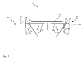
- a blocking device 29 This secures the two positioning sections 22a and 24a against undesired opening via the hinge means 26 when the bag section 210 reaches the filling station 10.
- the two blocking devices 29 fold into the dashed position, so that now opening of the positioning sections 22a and 24a via the hinge means 26 for the passage of the bag section 210 becomes possible.
- a height adjustment 32 of the attachment interfaces 30 can be seen.
- a slot is formed in each of the two attachment interfaces 30, so that a height displacement of the two attachment interfaces 30 relative to the frame 40 can take place.
Landscapes
- Engineering & Computer Science (AREA)
- Mechanical Engineering (AREA)
- Supplying Of Containers To The Packaging Station (AREA)
- Basic Packing Technique (AREA)
Abstract
Description
- Die vorliegende Erfindung betrifft eine Station einer Sackfüllanlage zur Befüllung mit Schüttgut sowie eine Sackfüllanlage für die Befüllung von Sackabschnitten einer Folienbahn mit Schüttgut.
- Es ist bekannt, dass Sackfüllanlagen für die Befüllung von Sackabschnitten einer Folienbahn mit Schüttgut zur Verfügung gestellt werden. Diese Sackfüllanlagen weisen eine Vielzahl von Bearbeitungsstationen auf, zu welchen auch eine Füllstation gehört. Eine solche Füllstation ist üblicherweise mit einem Fülltrichter ausgebildet, durch welchen das Schüttgut in den Zwischenraum innerhalb zweier Seitenlagen des Sackabschnitts gelangt. In der Füllstation ist der Sackabschnitt bereits an seinem Bodenende mit einer Bodennaht gesiegelt. Der Transport innerhalb der Sackfüllanlage zwischen den einzelnen Stationen erfolgt üblicherweise taktweise durch Greifvorrichtungen. Diese können als Pendelvorrichtung ausgebildet sein und bewegen dementsprechend die einzelnen Sackabschnitte im Wesentlichen in einer horizontalen Richtung weiter. Durch den taktweisen Vorschub erfährt der jeweilige Sackabschnitt zu Beginn der Transportbewegung eine Beschleunigung und zum Ende der jeweiligen Transportbewegung eine Abbremssituation. Da die Greifvorrichtung üblicherweise den Sackabschnitt im Bereich seines Kopfendes greift, führt dieses Beschleunigen und insbesondere das Abbremsen dazu, dass durch die Massenträgheit das Bodenende des Sackabschnitts nachpendelt bzw. beim Bremsen weiterpendelt.
- Das voranstehende Phänomen der Massenträgheit ist insbesondere im Bereich der Füllstation einer Sackfüllanlage nachteilig. So führt beim Abbremsen beim Antransport des Sackabschnitts in die Füllstation die Massenträgheit dazu, dass das Bodenende des Sackabschnitts weiterpendelt und dementsprechend der Sackabschnitt schräg oder im Wesentlichen schräg unter dem Fülltrichter der Füllstation angeordnet wird. Beim Befüllen kann dies zu unerwünschten mechanischen Belastungen einzelner Bereiche des Sackabschnitts führen. Auch ist für den nachfolgenden Weitertransport, insbesondere auf einem Transportband innerhalb der Füllstation, diese geometrische Korrelation nachteilig. Dieses Problem wird bisher ausschließlich durch entsprechende Ausbildung des Förderbandes versucht zu beheben. So sind Stollen bekannt, welche auf dem Förderband mitlaufend angeordnet sind und ein Weiterschwingen des Sackabschnitts beim Erreichen der Füllstation verhindern sollen. Diese Stollensysteme sind jedoch sehr aufwendig und kostenintensiv in der Produktion und Herstellung einer solchen Sackfüllanlage. Auch muss ein entsprechend größerer Bauraum für die Stollen für ein entsprechendes Förderband zur Verfügung gestellt werden.
- Es ist Aufgabe der vorliegenden Erfindung, die voranstehend beschriebenen Nachteile zumindest teilweise zu beheben. Insbesondere ist es Aufgabe der vorliegenden Erfindung, in kostengünstiger und einfacher Weise das Weiterschwingen des Bodenabschnitts aufgrund seiner Massenträgheit zu vermeiden oder zumindest zu reduzieren. Insbesondere sollen definierte Positionierungen des Sackabschnitts und insbesondere dessen Bodenabschnitt innerhalb der Station erfolgen.
- Voranstehende Aufgabe wird gelöst durch eine Station mit den Merkmalen des Anspruchs 1 und einer Sackfüllanlage mit den Merkmalen des Anspruchs 11. Weitere Merkmale und Details der Erfindung ergeben sich aus den Unteransprüchen, der Beschreibung und den Zeichnungen. Dabei gelten Merkmale und Details, die im Zusammenhang mit der erfindungsgemäßen Station beschrieben sind, selbstverständlich auch im Zusammenhang mit der erfindungsgemäßen Sackfüllanlage und jeweils umgekehrt, so dass bezüglich der Offenbarung zu den einzelnen Erfindungsaspekten stets wechselseitige Bezug genommen wird bzw. werden kann.
- Eine erfindungsgemäße Station, insbesondere eine Füllstation, einer Sackfüllanlage zur Befüllung von Schüttgut weist eine Positioniervorrichtung für die Positionierung eines Bodenabschnitts eines Sackabschnitts einer Folienbahn auf. Diese Positioniervorrichtung ist mit einem ersten Positionierelement und einem zweiten Positionierelement ausgestattet, wobei die beiden Positionierelemente über Befestigungsschnittstellen an einem Rahmen der Station, insbesondere der Füllstation, befestigt sind. Weiter weisen die beiden Positionierelemente jeweils mindestens einen Positionierabschnitt auf, welcher sich quer zur Transportrichtung des Sackabschnitts durch die Station, insbesondere die Füllstation, erstreckt und innerhalb der Station, insbesondere unterhalb des Fülltrichters der Füllstation, angeordnet ist.
- Erfindungsgemäß kann die Station in unterschiedlichster Weise ausgebildet sein. So ist es möglich, dass es sich bei der Station um eine Bodennahtsiegelstation, eine Füllstation, eine Kopfnahtsiegelstation und/oder eine Kopfnahtkühlstation handelt. Nachfolgend wird beispielhaft die Funktion der erfindungsgemäßen Station anhand der beispielhaften Verwendung in eine Füllstation beschrieben, wobei die Erfindung nicht auf diese Art der Station beschränkt ist. Der Begriff der Füllstation wird demnach nachfolgend als Synonym für eine Station einer Sackfüllanlage im Allgemeinen verwendet.
- In erfindungsgemäßer Weise wird also ein zusätzliches Element in Form der Positioniervorrichtung eingesetzt, um das Durchschwingen des Bodenabschnitts beim Erreichen der Füllstation zu verhindern. Dies ist die Positioniervorrichtung, wobei die aktiven Elemente hinsichtlich der Positionierung die beiden Positionierabschnitte darstellen. Sie sind hinsichtlich ihrer geometrischen Korrelation exakt zu dem Fülltrichter der Füllstation angeordnet. So erstrecken sie sich quer zur Transportrichtung des Sackabschnitts, ragen also in die Transportrichtung des Sackabschnitts hinein. Ein Sackabschnitt, welcher in die Füllstation eingebracht bzw. hineintransportiert wird und dort abbremst, erzeugt über die Massenträgheit ein Weiterschwingen des Bodenabschnitts des Sackabschnitts. Dieser kann nun an den sich quer zu seiner Transportrichtung erstreckenden Positionierelementen anschlagen. Um sicherzustellen, dass in gewünschter Weise auch mit Bezug auf die Transportrichtung eine ideale oder optimierte Korrelation des Sackabschnitts zu einem Fülltrichter erfolgt, sind die beiden Positionierabschnitte unterhalb des Fülltrichters angeordnet. Dabei kann eine Anordnung direkt unterhalb des Fülltrichters, also unterhalb der Mittellinie des Fülltrichters von Vorteil sein. Auch eine davon versetzte Anordnung ist möglich und ebenfalls unter dem Begriff einer Anordnung unterhalb des Fülltrichters zu verstehen.
- Darüber hinaus sind die Positionierelemente derart quer zur Transportrichtung ausgebildet, dass sie in den Transportweg des Sackabschnitts hineinragen. Mit anderen Worten kollidieren der Sackabschnitt und die Positionierabschnitte der Positioniervorrichtung beim Hineintransport des Sackabschnitts in die Füllstation miteinander. Damit wird die in erfindungsgemäßer Weise erwünschte definierte Positionierung auch für den Bodenabschnitt des Sackabschnitts zur Verfügung gestellt.
- Durch die definierte Positionierung ist nun für den gesamten Befüllvorgang nicht nur das Kopfende des Sackes, sondern auch dessen Bodenabschnitt des Sackabschnitts genau hinsichtlich seiner Lage definiert, so dass unerwünschte mechanische Belastungen reduziert oder sogar vollständig vermieden werden können. Ein Sackabschnitt weist erfindungsgemäß einen Bodenabschnitt und einen Kopfabschnitt auf. Diese beiden Abschnitte definieren sich durch die Schwerkraftausrichtung. So ist das obere Ende mit Bezug auf die Schwerkraftrichtung das Kopfende des Sackes, an welchem sich der Kopfabschnitt anschließt. Das gegenüberliegende Ende des Sackes kann als Bodenende bezeichnet werden, an welchen sich der Bodenabschnitt anschließt.
- Die beiden Positionierelemente sind stationär an dem Rahmen der Füllstation angeordnet. Eine Bewegung der Positionierelemente ist grundsätzlich nicht vorgesehen. Jedoch ist es möglich, dass die Positionierabschnitte, wie dies später noch erläutert wird, eine bewegbare Lagerung oder eine Bewegung über Scharniermittel erlauben. Grundsätzlich ist jedoch jede Form von Positionierabschnitten denkbar, auch stationäre Ausbildungen. Bei einer stationären Ausbildung reicht es aus, wenn die Positioniermittel den Sackabschnitt beim Erreichen der Füllstation, also in leerem Zustand, in der definierten Position abbremsen. Während des Befüllens des Sackes weitet sich dieser in Transportrichtung auf seine gefüllte Sackbreite auf. Hierfür ist es notwendig, dass quasi eine Einschnürung der gesamten Sackbreite quer zur Transportrichtung erfolgt, da dieses Material durch die Aufweitung die Sackbreite zur Verfügung stellt. Mit anderen Worten kann es sein, dass sich die Sackbreite quer zur Transportrichtung während des Füllvorgangs des Sackabschnitts reduziert. Dabei kann der Abstand als Durchlassabstand zwischen den beiden Positionierabschnitten derart gewählt sein, dass er kleiner ist als die Breite des Sackabschnittes im leeren Zustand quer zur Transportrichtung und größer oder gleich der Breite des Sackabschnitts quer zur Transportrichtung in dessen vollen Zustand. Somit wird auch ohne jegliche Bewegbarkeit der Positionsabschnitte die erfindungsgemäße Wirkungsweise der Positioniervorrichtung erreicht.
- Unter der Transportrichtung ist erfindungsgemäß der Transport des Sackabschnitts zwischen den einzelnen Stationen zu verstehen. Üblicherweise nehmen Greifervorrichtungen eine klemmende Befestigung des jeweiligen Sackabschnitts vor und bewegen diesen somit, vorzugsweise im Pendelbetrieb, von Station zu Station. Damit wird eine definierte Transportrichtung vorgebbar, welche z.B. in einer Sackfüllanlage in Seitenansicht von rechts nach links erfolgen kann.
- In erfindungsgemäßer Weise wird nun beim Antransport eines Sackabschnitts in die Füllstation durch eine Greifvorrichtung dieser Sackabschnitt beim Erreichen der Füllstation an seinem Kopfende durch die Greifvorrichtung abgebremst. Das Bodenende des Sackabschnitts ist nicht an der Greifvorrichtung direkt befestigt, so dass durch die Massenträgheit des Materials des Sackabschnitts ein Weiterschwingen des Bodenabschnitts erfolgen würde. Dieses Weiterschwingen wird jedoch durch die Positionierabschnitte der Positioniervorrichtung verhindert, da sozusagen ein Anschlagen des Bodenabschnitts an den Positionierabschnitten der Positioniervorrichtung erfolgt. Anschließend kann in dieser definierten Position des Sackabschnitts der Füllvorgang in der Füllstation für den Sackabschnitt erfolgen. Der gefüllte Sackabschnitt wird nun weitertransportiert zur nächsten Station, z.B. einer Kopfnahtsiegelstation. Hierfür kann ein entsprechender Durchlass zwischen den beiden Positionsabschnitten vorgesehen sein, wie er bereits erläutert worden ist. Auch eine bewegbare bzw. elastisch verformbare Ausbildung der Positionierabschnitte ist für diesen Durchlass von Vorteil bzw. möglich.
- Bei einer Sackfüllanlage für eine erfindungsgemäße Füllstation handelt es sich insbesondere um eine Anlage gemäß dem Form-Fill-and-Seal-(FFS)-Verfahren. Dabei wird, ausgehend von einer Vorlagerolle, eine Folienbahn kontinuierlich abgerollt. Diese Folienbahn ist vorzugsweise als Schlauchfolienbahn ausgebildet und wird über eine Puffervorrichtung, z.B. eine Tänzervorrichtung, in einen taktweisen Vorschub umgewandelt. Anschließend sind verschiedene Stationen zur Bearbeitung der Folienbahn vorgesehen. Zuerst wird über eine Bodennahtsiegelstation mit einer Schneidvorrichtung die Bodennaht gesiegelt und ein Ablängen der Sackabschnitte erzeugt. Die einzelnen Sackabschnitte werden über Greifervorrichtungen weitertransportiert zur Füllstation, weiter zur Kopfnahtsiegelstation und abschließend zur Kopfnahtkühlstation. Der Transport der befüllten Sackabschnitte kann zusätzlich unterstützt werden durch ein Transportband, welches ab der Füllstation eine Unterstützung des Bodenendes des Sackabschnitts zur Verfügung stellen kann.
- Es kann von Vorteil sein, wenn bei einer erfindungsgemäßen Füllstation die beiden Positionierabschnitte quer zur Transportrichtung des Sackabschnitts voneinander einen Durchlassabstand aufweisen, welcher kleiner als die Breite des Sackabschnitts quer zur Transportrichtung ausgebildet ist. Dabei bezieht sich der Durchlassabstand hinsichtlich einer kleineren Ausbildung insbesondere auf die Breite des Sackabschnitts quer zur Transportrichtung in dessen leerem Zustand. Vorzugsweise ist der Durchlassabstand größer oder gleich der Breite des Sackabschnitts quer zur Transportrichtung in dessen vollem Zustand, insbesondere dann, wenn die Positionierabschnitte eine unflexible und damit stationäre Ausbildung aufweisen. Für das Durchlassen bei flexibel ausgestalteten Positionierabschnitten ist nun eine geringere Bewegbarkeit der Positionierabschnitte notwendig, selbst wenn ein Verbiegen bzw. eine Rotation notwendig ist. Der teilweise Durchlass durch den Durchlassabstand erlaubt also eine Reduktion der notwendigen Bewegbarkeit der Positionierabschnitte. Dies führt zu einfacher und kostengünstiger Konstruktion entsprechender Scharniermittel, wie sie später noch erläutert werden. Auch erfolgt eine deutlich schnellere Rückstellung der Positionierabschnitte über die Scharniermittel, so dass die Taktzeit in der Füllstation nicht negativ beeinflusst wird oder sogar positiv reduziert werden kann.
- Weiter ist es von Vorteil, wenn bei einer erfindungsgemäßen Füllstation die Positionierabschnitte über Scharniermittel an den Befestigungsschnittstellen angeordnet sind, wobei insbesondere die Schwenkachse der Scharniermittel vertikal ausgerichtet ist. Scharniermittel dienen also zur Beweglichkeit der Positionierabschnitte relativ zu den Befestigungsschnittstellen. Sie erzeugen also eine Rotierbarkeit der Positionierabschnitte um eine Schwenkachse, welche durch die Scharniermittel definiert wird. Die vertikale Ausrichtung der Schwenkachse ist dabei bevorzugt auf die Schwerkraftrichtung bezogen, so dass die Schwenkachse sich entlang der Schwerkraftrichtung erstreckt. Die Scharnierwirkung wird insbesondere für den Durchlass des befüllten Sackabschnitts benötigt. Damit wird der Durchlassabstand unabhängig von der Durchlassfähigkeit der beiden Positionierabschnitte ausgebildet. Bevorzugt ist jedoch ein möglichst großer Durchlassabstand in Kombination mit den Scharniermitteln, um, wie bereits beschrieben worden ist, die Taktzeit durch besonders schnelle Rückstellung in der Füllstation reduzieren zu können. Selbstverständlich sind die Scharniermittel separat von den Positionierabschnitten ausbildbar. Auch ist es möglich, dass die Positionierabschnitte die Scharniermittel direkt aufweisen, z.B. durch flexible Ausbildung einzelner Abschnitte der Positionierabschnitte. Auch ein Anschlag für die Positionierabschnitte ist möglich, um in eine definierte Endposition der Positionierabschnitte in Positionierposition und in Durchlassposition zu ermöglichen.
- Vorteilhaft ist es weiter, wenn bei einer erfindungsgemäßen Füllstation die Scharniermittel als elastisch verformbarer Abschnitt der Positionierabschnitte ausgebildet sind. Damit können die Positionierabschnitte teilweise oder sogar vollständig selbst aus elastischem Material ausgebildet sein. Ein Verformen bringt sozusagen den gewünschten Durchlass für den gefüllten Sackabschnitt aus der Füllstation heraus mit sich. Beispielsweise sind die Positionierabschnitte teilweise aus einem Elastomermaterial hergestellt. Auch flexible Schläuche aus Kunststoff sind für die Positionierabschnitte verwendbar. Insbesondere ist somit das Scharniermittel in Funktionseinheit gemeinsam mit dem jeweiligen Positionierabschnitt ausgebildet.
- Ein weiterer Vorteil wird erzielt, wenn bei einer erfindungsgemäßen Füllstation die Positioniervorrichtung für jeden Positionierabschnitt eine Rückstellvorrichtung aufweist, welche die Scharniermittel und/oder die Positionierabschnitte jeweils mit einer Rückstellkraft beaufschlagt. Dabei kann es sich z.B. um eine Federvorrichtung handeln. So werden elastische Rückstellkräfte im Positionierabschnitt und/oder im Scharniermittel erzeugt, um die Rückstellung in definierter Weise und vor allem noch schneller erzeugen zu können. Diese Rückstellvorrichtung ist vorzugsweise einstellbar, wie dies später noch erläutert wird. Darüber hinaus erzeugt die Rückstellkraft eine ausreichende Gegenkraft, so dass die Massenträgheit des Sackabschnitts in dessen Bodenabschnitt nicht ein unerwünschtes Weiterbewegen der Positionierabschnitte zur Folge hat. Somit wird mit höherer Sicherheit die Positionierung auch bei bewegbar über die Scharniermittel gelagerten Positionierabschnitten möglich.
- Bei einer Füllstation gemäß dem voranstehenden Absatz kann es von Vorteil sein, wenn die Positioniervorrichtung eine Einstellvorrichtung aufweist für die Einstellung und/oder Variation der Rückstellkraft. So kann eine Anpassung z.B. durch eine verstellbare Feder erfolgen. Die aktive Rückstellung kann sowohl hydraulisch, als auch pneumatisch oder über die bereits beschriebene Federvorrichtung erfolgen. Damit kann die Rückstellkraft an die jeweilige Taktgeschwindigkeit der Maschine und insbesondere die Taktzeit der Füllstation angepasst werden. Beispielsweise kann bei einer Ausbildung der Scharniermittel als schlauchartige und flexible Ausbildung der Positionierabschnitte eine Luftfüllung des Schlauches eine Flexibilitätsänderung mit sich bringen. Auch eine Variation von Federvorspannungen innerhalb einer solchen Rückstellvorrichtung kann als Einstellvorrichtung dienen.
- Ein weiterer Vorteil wird erzielt, wenn bei einer erfindungsgemäßen Füllstation die Scharniermittel eine Blockiervorrichtung aufweisen, welche die Schwenkbewegung der Scharniermittel um die Schwenkachse definiert, insbesondere gesteuert oder geregelt, blockieren kann. Die Blockiervorrichtung dient also dazu, insbesondere unabhängig von dem Vorhandensein einer Rückstellvorrichtung, die Scharniermittel gegen eine unerwünschte Bewegung während der Positionierwirkung, also beim Erreichen des Sackabschnitts in der Füllstation, zu blockieren. Wird der Sackabschnitt in die Füllstation eintransportiert, schwingt durch Massenträgheit der Bodenabschnitt des Sackabschnitts gegen die Positioniermittel. Dies kann durch die Massenträgheit eine so starke Krafteinwirkung auf die Positionierabschnitte mit sich bringen, dass diese die Scharniermittel über ihre Schwenkachse bewegen würden. Ist keine Rückstellvorrichtung mit einer Rückstellkraft vorhanden, kann über die Blockiervorrichtung eine Blockade einer solchen unerwünschten Öffnung für den hier noch unerwünschten Durchlass durch die Positionierabschnitte zur Verfügung gestellt werden. Während des Füllvorgangs oder spätestens nach dem Füllvorgang werden die Blockiervorrichtungen hinsichtlich einer Deblockade gesteuert bzw. geregelt, um den erfindungsgemäßen Durchlass des gefüllten Sackabschnitts zu ermöglichen.
- Vorteilhaft ist es ebenfalls, wenn bei einer erfindungsgemäßen Füllstation die Positionierabschnitte in Transportrichtung des Sackabschnitts um einen Sackversatz von der Mittellinie der Station, insbesondere des Fülltrichters der Füllstation, beabstandet sind. Dabei ist der Sackversatz insbesondere kleiner oder gleich der halben Transportbreite des gefüllten Sackabschnittes in Transportrichtung ausgebildet. Die halbe Transportbreite des Sackabschnitts ist also die Hälfte der gesamten Transportbreite des gefüllten Sackabschnitts, so dass sich der Sackabschnitt im Wesentlichen symmetrisch um die Mittellinie des Fülltrichters ausbildet. Dies führt dazu, dass zwar grundsätzlich ein Weiterschwingen des Bodenabschnitts des Sackabschnitts erlaubt wird, jedoch nur bis maximal zu dem um den Sackversatz beabstandeten jeweiligen Positionierabschnitt. Damit wird sichergestellt, dass während des Füllvorgangs des Sackabschnitts keine unerwünschte Beeinflussung der Positionierabschnitte und damit eine Blockade des jeweiligen Seitenabschnitts des Sackabschnitts erfolgt. Erst wenn der Sackabschnitt komplett gefüllt ist, liegt durch die Beabstandung mit Hilfe des Sackversatzes der Sackabschnitt an seiner Seite komplett an den beiden Positionierabschnitten an. Damit wird eine noch bessere Durchführung des Füllvorgangs erzielt. Ein Aufweiten des Sackabschnitts wird nicht durch die Positionierabschnitte dieser Ausführungsform verhindert.
- Es kann von Vorteil sein, wenn bei einer erfindungsgemäßen Station die Befestigungsschnittstellen jeweils wenigstens eine Höhenverstellung aufweisen, mittels derer die Höhe bezogen auf den Fülltrichter variierbar ist. Damit ist es möglich auch die Höhe des jeweiligen Positionierelements anzupassen und zu variieren. Insbesondere erfolgt auf diese Weise eine Anpassung an die tatsächliche geometrische Ausbildung des jeweils im Einsatz befindlichen Sacks. Damit kann die gewünschte Beeinflussung des Sacks während der Bearbeitung noch gezielter erfolgen. Die Variation der Höhe kann dabei sowohl manuell, als auch automatisch, z. B. elektromechanisch angetrieben, erfolgen.
- Bei der Ausführungsform des voranstehenden Absatzes kann es vorteilhaft sein, wenn die Höhenverstellung wenigstens ein Langloch in der jeweiligen Befestigungsschnittstelle und wenigstens ein Schraubmittel für die Befestigung an dem Rahmen aufweist. Mit anderen Worten kann insbesondere mittels Schrauben als Schraubmittel eine Verschiebung in Höhenrichtung durch die Ausbildung als Langloch freigegeben oder gesperrt werden. Nach dem Einstellen der gewünschten Höhe für die Positionierelemente werden die Schrauben auf beiden Seiten angezogen und damit die eingestelle Höhe mittels der Höhenverstellung fixiert. Hierbei handelt es sich um eine besonders einfache und kostengünstige Ausführungsform einer Höhenverstellung. Selbstverständlich kann das Langloch für die Höhenverstellung auch in dem Rahmen angeordnet sein.
- Ebenfalls Gegenstand der vorliegenden Erfindung ist eine Sackfüllanlage für die Befüllung von Sackabschnitten einer Folienbahn mit Schüttgut, aufweisend eine erfindungsgemäße Füllstation. Dementsprechend bringt eine erfindungsgemäße Sackfüllanlage die gleichen Vorteile mit sich, wie sie ausführlich mit Bezug auf eine erfindungsgemäße Füllstation erläutert worden sind. Mittels Greifvorrichtungen, welche ebenfalls Teil der Sackfüllanlage seien können, wird der Transport zwischen den einzelnen Stationen der Sackfüllanlage zur Verfügung gestellt. Die Sackfüllanlage ist insbesondere als FFS-Anlage, als Form-Fill-and-Seal-Anlage, ausgebildet.
- Die Sackfüllanlage gemäß dem voranstehenden Absatz kann dahingehend weitergebildet werden, dass in der Füllstation ein Transportband angeordnet ist, für den taktweisen Transport der Sackabschnitte in und nach der Füllstation. Insbesondere nach wenigstens einer weiteren Station, z.B. einer Kopfnahtsiegelstation und/oder einer Kopfnahtkühlstation, ist ein Abtransport angeordnet für den kontinuierlichen Abtransport der Sackabschnitte. Das Abtransportband kann z.B. eine ansteigende Ausrichtung mit sich vergrößerndem Höhenniveau aufweisen. Dadurch, dass erfindungsgemäß das Transportband nun nicht mehr für die definierte Positionierung des Bodenabschnitts der Sackabschnitte benötigt wird, kann dieses einfacher und kostengünstiger ausfallen. Auch wird es möglich, dass ein Umfallen der Sackabschnitte in gefülltem Zustand bei der Übergabe vom Transportband auf das Abtransportband in definierter Weise erfolgt. So kippen hier die Sackabschnitte entgegen der Transportrichtung um, so dass bei einem ansteigendem Transport beim Abtransportband nunmehr der tiefste Punkt der Kopfabschnitt des befüllten Sackes ist. Da während der Befüllung mit Schüttgut der Bodenabschnitt des Sackabschnitts mit der höchsten Dichte des Schüttguts erzeugt wird, erfüllt das Umkippen in der definierten Weise und das ansteigende Transportieren mit Hilfe des Abtransportbands ein Auflockern und ein Verteilen des Schüttguts innerhalb des Sackabschnitts.
- Weitere Vorteile, Merkmale und Einzelheiten der Erfindung ergeben sich aus der nachfolgenden Beschreibung, in der unter Bezugnahme auf die Zeichnungen Ausführungsbeispiele der Erfindung im Einzelnen beschrieben sind. Dabei können die in den Ansprüchen und in der Beschreibung erwähnten Merkmale jeweils einzeln für sich oder in beliebiger Kombination erfindungswesentlich sein. Es zeigen schematisch:
- Fig. 1
- eine Ausführungsform einer erfindungsgemäßen Sackfüllanlage,
- Fig. 2
- eine Ausführungsform einer erfindungsgemäßen Füllstation,
- Fig. 3
- die Ausführungsform der
Fig. 2 in Richtung der Transportrichtung gesehen, - Fig. 4
- die Ausführungsform der
Fig. 2 und3 in Draufsicht, und - Fig. 5
- eine weitere Ausführungsform einer erfindungsgemäßen Füllstation.
- In
Fig. 1 ist schematisch eine Ausführungsform einer erfindungsgemäßen Sackfüllanlage 100 dargestellt. Von einer Vorlagenrolle rechts wird kontinuierlich zu einer Puffervorrichtung hin eine Folienbahn 200 abgerollt. Ab der Puffervorrichtung erfolgt der Vorschub der Folienbahn 200 in schubweiser Vorzugsart. Eine erste Station 170 ist als Bodennahtsiegelstation mit einer Schneidvorrichtung zum Ablängen der Sackabschnitte 210 ausgebildet. Über nicht näher dargestellte Greifervorrichtungen erfolgt nun ein Transport der Sackabschnitte von rechts nach links zu den weiteren Stationen 170. Als nächste Station ist zuerst eine Füllstation 10 vorgesehen, die einen Fülltrichter 50 für die Befüllung des Sackabschnitts 210 mit Schüttgut aufweist. Nachfolgend sind als weitere Stationen 170 noch eine Kopfnahtsiegelstation und eine Kopfnahtkühlstation vorgesehen. Ab der Füllstation 10 ist ein Transportbahn 60 vorhanden, welches eine Unterstützung des Bodenabschnitts des Sackabschnitts 210 zur Verfügung stellt. Nachfolgend an das Transportband 60 ist ein ansteigend ausgebildetes Abtransportband 70 für die kontinuierliche Abförderung der gefüllten Sackabschnitte 210 vorgesehen. Ebenfalls bereits zu erkennen ist eine Ausführungsform einer erfindungsgemäßen Positioniervorrichtung 20, welche hier in Seitenansicht das erste Positioniermittel 22 zeigt. Eine Befestigung der Positionierelemente 22 erfolgt über die Befestigungsschnittstellen 30. -
Fig. 2 ,3 und 4 zeigen schematisch eine erste Ausführungsform einer erfindungsgemäßen Füllstation 10. Diese weist einen Fülltrichter 50 auf, über welchen eine Befüllung mit Schüttgut erfolgt. Der Fülltrichter 50 ist vorzugsweise als kegelstumpfförmige Form ausgewählt, welche rotationssymmetrisch mit einer Mittellinie 52 ausgestattet ist. InFig. 2 ist gut zu erkennen, wie über eine Greifervorrichtung von rechts nach links eine Förderung des Sackabschnitts 210 erfolgt. Befindet sich der Sackabschnitt 210 bereits in der Füllstation 10, so wird er von oben befüllt. Mit gepunkteter Linie ist dabei die teilbefüllte Kontur des Sackabschnitts 210 inFig. 2 dargestellt. - Eine erfindungsgemäße Positioniervorrichtung 20 einer Füllstation 10 funktioniert in der nachfolgend beschriebenen Weise. Ein Sackabschnitt 210 wird, in
Fig. 2 von rechts nach links, zu der Füllstation 10 gefördert. Beim Erreichen der Füllstation 10 bremst die entsprechende Greifvorrichtung ab und der Bodenabschnitt 212 des Sackabschnitts 210 wird durch entsprechende Massenträgheit weiterschwingen. Dieses Weiterschwingen des Bodenabschnitts 212 wird von der Positioniervorrichtung 20 und hier von den Positionierabschnitten 22a und 24a der Positionierelemente 22 und 24 gestoppt. Damit erfolgt eine definierte Positionierung des Sackabschnitts 210 unterhalb des Fülltrichters 50. - Nachfolgend erfolgt der Füllvorgang des Sackabschnitts 210 bis eine vollständige Befüllung fertiggestellt ist. Nach dem Befüllen muss ein Durchtreten und ein Weitertransport des Sackabschnitts 210 mit einer Greifervorrichtung und/oder dem Transportband 60 erfolgen. Hierfür sind die Positionierelemente 22 und 24 dieser Ausführungsform mit Scharniermitteln 26 ausgebildet, die über eine Scharnierachse S eine Schwenkbewegung der Positionierabschnitte 22a und 24a ermöglichen. Damit erfolgt der Durchlass durch den Durchlassabstand D, welcher sich durch das Verschwenken vergrößern lässt. Nachfolgend wird z.B. über eine Rückstellvorrichtung 28, wie sie in dieser Ausführungsform nicht näher erläutert ist, ein Zurückschwenken der Positionierabschnitte 22a und 24a erfolgen, um den nachfolgenden Sackabschnitt 210 bei dessen Erreichen in der Füllstation 10 wieder positionieren zu können.
- In
Fig. 3 ist gut zu erkennen, wie eine Korrelation zwischen dem Durchlassabstand D und der Breite B quer zur Transportrichtung T vorliegen kann. InFig. 2 ist gut zu erkennen, dass ein Versatz der Positionierabschnitte 22a und 24a um einen Sackversatz V von der Mittellinie 52 in Transportrichtung T vorgesehen sein kann. Dieser Sackversatz V ist vorzugsweise kleiner oder gleich der Transportbreite TB in Richtung der Transportrichtung T des Sackabschnitts 210. - In der
Fig. 5 ist eine weitere Ausführungsform einer erfindungsgemäßen Füllstation 10 dargestellt. Bei dieser ist eine Positioniervorrichtung 20 vorgesehen, welche explizit ausgebildete Scharniermittel 26, z.B. als Rotationslager, aufweist. Eine Rückstellvorrichtung 28 erlaubt eine einstellbare Einbringung einer Rückstellkraft auf die Scharniermittel 26. In gestrichelten Linien ist der geöffnete Zustand für den Durchlass des Sackabschnitts 210 dargestellt. Auch ist inFig. 5 eine Ausführungsmöglichkeit einer Blockiervorrichtung 29 zu erkennen. Diese sichert die beiden Positionierabschnitte 22a und 24a gegen ein unerwünschtes Öffnen über die Scharniermittel 26, wenn der Sackabschnitt 210 die Füllstation 10 erreicht. Bereits während dem Befüllen oder spätestens nach dem Befüllen klappen die beiden Blockiervorrichtungen 29 in die gestrichelte Position, so dass nunmehr ein Öffnen der Positionierabschnitte 22a und 24a über die Scharniermittel 26 für den Durchlass des Sackabschnitts 210 möglich wird. - In den
Fig. 2 und3 ist weiter eine Höhenverstellung 32 der Befestigungsschnittstellen 30 zu erkennen. Zum Beispiel ist in den beiden Befestigungsschnittstellen 30 jeweils ein Langloch ausgebildet, so dass eine Höhenverschiebung der beiden Befestigungsschnittstellen 30 relativ zum Rahmen 40 erfolgen kann. Nach dem Einstelllen erfolgt die Fixierung mittels hier jeweils zwei Schraubmitteln in Form von Schrauben. - Die voranstehende Erläuterung der Ausführungsformen beschreibt die vorliegende Erfindung ausschließlich im Rahmen von Beispielen. Selbstverständlich können einzelne Merkmale der Ausführungsformen, sofern technisch sinnvoll, frei miteinander kombiniert werden, ohne den Rahmen der vorliegenden Erfindung zu verlassen.
-
- 10
- Füllstation
- 20
- Positioniervorrichtung
- 22
- erstes Positionierelement
- 22a
- Positionierabschnitt
- 24
- zweites Positionierelement
- 24a
- Positionierabschnitt
- 26
- Scharniermittel
- 28
- Rückstellvorrichtung
- 29
- Blockiervorrichtung
- 30
- Befestigungsschnittstellen
- 32
- Höhenverstellung
- 40
- Rahmen
- 50
- Fülltrichter
- 52
- Mittellinie
- 60
- Transportband
- 70
- Abtransportband
- 100
- Sackfüllanlage
- 170
- Station
- 200
- Folienbahn
- 210
- Sackabschnitt
- 212
- Bodenabschnitt
- D
- Durchlassabstand
- B
- Breite des Sackabschnitts quer zu Transportrichtung
- TB
- Transportbreite des Sackabschnitts in Transportrichtung
- S
- Schwenkachse der Scharniermittel
- T
- Transportrichtung des Sackabschnitts
- V
- Sackversatz
Claims (12)
- Station (170), insbesondere Füllstation (10), einer Sackfüllanlage (100) zur Befüllung mit Schüttgut, aufweisend eine Positioniervorrichtung (20) für die Positionierung eines Bodenabschnitts (212) eines Sackabschnitts (210) einer Folienbahn (200), aufweisend ein erstes Positionierelement (22) und ein zweites Positionierelement (24), wobei die beiden Positionierelemente (22, 24) über Befestigungsschnittstellen (30) an einem Rahmen (40) Station (170), insbesondere der Füllstation (10), befestigt sind, und wobei die beiden Positionierelemente (22, 24) jeweils mindestens einen Positionierabschnitt (22a, 24a) aufweisen, welche sich quer zur Transportrichtung (T) des Sackabschnitts (210) durch die Station (170), insbesondere die Füllstation (10), erstrecken und innerhalb der Station (170), insbesondere unterhalb eines Fülltrichters (50) der Füllstation (10), angeordnet sind.
- Station (170) nach Anspruch 1, dadurch gekennzeichnet, dass die beiden Positionierabschnitte (22a, 24a) quer zur Transportrichtung (T) des Sackabschnitts (210) voneinander einen Durchlassabstand (A) aufweisen, welcher kleiner als die Breite (B) des Sackabschnitts (210) quer zur Transportrichtung (T) ausgebildet ist.
- Station (170) nach einem der vorangegangenen Ansprüche, dadurch gekennzeichnet, dass die Positionierabschnitte (22a, 24a) über Scharniermittel (26) an den Befestigungsschnittstellen (30) angeordnet sind, wobei insbesondere die Schwenkachse (S) der Scharniermittel (26) vertikal ausgerichtet ist.
- Station (170) nach Anspruch 3, dadurch gekennzeichnet, dass die Scharniermittel (26) als elastisch verformbarer Abschnitt der Positionierabschnitte (22a, 24a) ausgebildet sind.
- Station (170) nach einem der Ansprüche 3 oder 4, dadurch gekennzeichnet, dass die Positioniervorrichtung (20) für jeden Positionierabschnitt (22a, 24a) eine Rückstellvorrichtung (28) aufweist, welche die Scharniermittel (26) und/oder die Positionierabschnitte (22a, 24a) jeweils mit einer Rückstellkraft beaufschlagt.
- Station (170) nach Anspruch 5, dadurch gekennzeichnet, dass die Positioniervorrichtung (20) eine Einstellvorrichtung aufweist für die Einstellung und/oder Variation der Rückstellkraft.
- Station (170) nach einem de Ansprüche 3 bis 6, dadurch gekennzeichnet, dass die Scharniermittel (26) eine Blockiervorrichtung (29) aufweisen, welche die Schwenkbewegung der Scharniermittel (26) um die Schwenkachse (S) definiert, insbesondere gesteuert oder geregelt, blockieren kann.
- Station (170) nach einem der vorangegangenen Ansprüche, dadurch gekennzeichnet, dass die Positionierabschnitte (22a, 24a) in Transportrichtung (T) des Sackabschnitts (210) um einen Sackversatz (V) von der Mittellinie (52) der Station (170), insbesondere des Fülltrichters (50) der Füllstation (10), beabstandet sind, wobei der Sackversatz (V) insbesondere kleiner oder gleich der halben Transportbreite (TB) des gefüllten Sackabschnitts (210) in Transportrichtung (T) ausgebildet ist.
- Station (170) nach einem der vorangegangenen Ansprüche, dadurch gekennzeichnet, dass die Befestigungsschnittstellen (30) jeweils wenigstens eine Höhenverstellung (32) aufweisen, mittels derer die Höhe bezogen auf den Fülltrichter (50) variierbar ist.
- Station (170) nach Anspruch 9, dadurch gekennzeichnet, dass die Höhenverstellung (32) wenigstens ein Langloch in der jeweiligen Befestigungsschnittstelle (30) und wenigstens ein Schraubmittel für die Befestigung an dem Rahmen (40) aufweist.
- Sackfüllanlage (100) für die Befüllung von Sackabschnitten (210) einer Folienbahn (200) mit Schüttgut, aufweisend eine Station (170)mit den Merkmalen eines der Ansprüche 1 bis 10.
- Sackfüllanlage (100) nach Anspruch 11, dadurch gekennzeichnet, dass in der Füllstation (10) ein Transportband (60) angeordnet ist für den taktweisen Transport der Sackabschnitte (210) in und nach der Station (170), insbesondere nach wenigstens einer weiteren Station (170), ein Abtransportband (70) angeordnet ist für den kontinuierlichen Abtransport der Sackabschnitte (210).
Priority Applications (1)
| Application Number | Priority Date | Filing Date | Title |
|---|---|---|---|
| PL14166136T PL2810881T3 (pl) | 2013-06-04 | 2014-04-28 | Stacja instalacji napełniania worków do napełniania materiałem sypkim |
Applications Claiming Priority (2)
| Application Number | Priority Date | Filing Date | Title |
|---|---|---|---|
| DE102013105757 | 2013-06-04 | ||
| DE102013109786.3A DE102013109786B4 (de) | 2013-06-04 | 2013-09-06 | Station einer Sackfüllanlage zur Befüllung mit Schüttgut |
Publications (2)
| Publication Number | Publication Date |
|---|---|
| EP2810881A1 true EP2810881A1 (de) | 2014-12-10 |
| EP2810881B1 EP2810881B1 (de) | 2018-03-28 |
Family
ID=50630599
Family Applications (1)
| Application Number | Title | Priority Date | Filing Date |
|---|---|---|---|
| EP14166136.3A Active EP2810881B1 (de) | 2013-06-04 | 2014-04-28 | Station einer Sackfüllanlage zur Befüllung mit Schüttgut |
Country Status (4)
| Country | Link |
|---|---|
| EP (1) | EP2810881B1 (de) |
| DE (1) | DE102013109786B4 (de) |
| ES (1) | ES2667583T3 (de) |
| PL (1) | PL2810881T3 (de) |
Cited By (1)
| Publication number | Priority date | Publication date | Assignee | Title |
|---|---|---|---|---|
| CN114715481A (zh) * | 2022-05-04 | 2022-07-08 | 展一智能科技(东台)有限公司 | 夹盖机构及包装箱整理机 |
Citations (3)
| Publication number | Priority date | Publication date | Assignee | Title |
|---|---|---|---|---|
| US20110239595A1 (en) * | 2010-03-30 | 2011-10-06 | Kraft Foods Global Brands Llc | Methods and apparatus for filling a container with a pouch and a flowable food product |
| WO2013018074A1 (en) * | 2011-08-04 | 2013-02-07 | Weicom S.R.L. | Apparatus and method for batching, packing and palletizing a granular product |
| EP2572996A1 (de) * | 2011-09-26 | 2013-03-27 | Teepack Spezialmaschinen Gmbh & Co. Kg | Verfahren und Vorrichtung zur Herstellung von Beuteln |
Family Cites Families (6)
| Publication number | Priority date | Publication date | Assignee | Title |
|---|---|---|---|---|
| DE565303C (de) * | 1930-10-03 | 1932-11-28 | Johannes Gravenholdt Dipl Ing | Sackhalter fuer selbsttaetige Fuell- und Waegemaschinen |
| DE6938621U (de) * | 1969-09-29 | 1970-01-22 | August Wickersheim Kg Fa | Vorrichtung zum verpacken von stueckigen guetern, insbesondere von in beuteln abgepackten kartoffeln od. dgl., in saecke |
| US4078358A (en) | 1976-08-31 | 1978-03-14 | National Distillers And Chemical Corporation | Bag-hanging and bag-filling machines adapted for synchronous and independent operation and method of using same |
| DE3118866C2 (de) | 1981-05-13 | 1984-04-12 | Haver & Boecker, 4740 Oelde | "Maschine zum Füllen und Verschließen von Säcken aus Kunststoff, vorzugsweise von Seitenfaltensäcken oder Flachsäcken" |
| IT1263250B (it) * | 1992-10-27 | 1996-08-05 | Macchina automatica per formare, riempire e sigillare sacchi e simili. | |
| EP1050458B1 (de) * | 1999-05-04 | 2006-10-25 | WindmÀ¶ller & Hölscher | Vorrichtung zum Befüllen und Verschliessen von Säcken |
-
2013
- 2013-09-06 DE DE102013109786.3A patent/DE102013109786B4/de active Active
-
2014
- 2014-04-28 EP EP14166136.3A patent/EP2810881B1/de active Active
- 2014-04-28 ES ES14166136.3T patent/ES2667583T3/es active Active
- 2014-04-28 PL PL14166136T patent/PL2810881T3/pl unknown
Patent Citations (3)
| Publication number | Priority date | Publication date | Assignee | Title |
|---|---|---|---|---|
| US20110239595A1 (en) * | 2010-03-30 | 2011-10-06 | Kraft Foods Global Brands Llc | Methods and apparatus for filling a container with a pouch and a flowable food product |
| WO2013018074A1 (en) * | 2011-08-04 | 2013-02-07 | Weicom S.R.L. | Apparatus and method for batching, packing and palletizing a granular product |
| EP2572996A1 (de) * | 2011-09-26 | 2013-03-27 | Teepack Spezialmaschinen Gmbh & Co. Kg | Verfahren und Vorrichtung zur Herstellung von Beuteln |
Cited By (2)
| Publication number | Priority date | Publication date | Assignee | Title |
|---|---|---|---|---|
| CN114715481A (zh) * | 2022-05-04 | 2022-07-08 | 展一智能科技(东台)有限公司 | 夹盖机构及包装箱整理机 |
| CN114715481B (zh) * | 2022-05-04 | 2023-08-15 | 展一智能科技(东台)有限公司 | 夹盖机构及包装箱整理机 |
Also Published As
| Publication number | Publication date |
|---|---|
| ES2667583T3 (es) | 2018-05-11 |
| DE102013109786B4 (de) | 2023-05-25 |
| EP2810881B1 (de) | 2018-03-28 |
| PL2810881T3 (pl) | 2018-08-31 |
| DE102013109786A1 (de) | 2014-12-04 |
Similar Documents
| Publication | Publication Date | Title |
|---|---|---|
| DD201661A5 (de) | Verfahren und vorrichtung zur verhinderung der verdrehung eines flexiblen schlauchriemens in einem schlauchriemenfoerderer | |
| EP2624976A1 (de) | Vorrichtung zur drahtzuführung an drahtverarbeitungsmaschinen | |
| EP1537037A1 (de) | Vorrichtung zum aufteilen eines ungeordneten stromes von zylindrischen gegenständen, zum beispiel getränkeflaschen, auf mehrere gassen | |
| DE102015113435A1 (de) | Transportvorrichtung sowie Transportverfahren mit einer derartigen Transportvorrichtung | |
| DE69819402T2 (de) | Sich automatisch anpassender Former in einer Verpackungsvorrichtung und Betriebsverfahren | |
| WO2018184795A1 (de) | Vorrichtung zum verpacken von arzneimittelportionen | |
| DE2140088A1 (de) | Antriebssystem fur eine Bahnver arbeitungsvorrichtung | |
| DE69701377T2 (de) | Verfahren und Vorrichtung zum Bedrucken einer Verpackungsbahn in einer Schlauchbeutelmaschine | |
| EP3453648B1 (de) | Zulaufvorrichtung | |
| WO2014053253A1 (de) | Transportvorrichtung für güter sowie verfahren zum betreiben einer transportvorrichtung | |
| DE102010023384B4 (de) | Herstellungsverfahren, insbesondere für Rohre und Abreißvorrichtung | |
| EP2810881B1 (de) | Station einer Sackfüllanlage zur Befüllung mit Schüttgut | |
| EP0119957B2 (de) | Formvorrichtung zur Bildung eines Einflossenschlauches | |
| EP1736412A1 (de) | Clipmaschine | |
| DE102012106827B3 (de) | Längstrennschweißeinrichtung mit verbesserter Austreibvorrichtung und Verfahren zum Austreiben eines Folienüberstandes | |
| EP2810880B1 (de) | Öffnungsvorrichtung für das Öffnen eines Sackabschnittts einer Folienbahn in einer Sackfüllanlage | |
| DE69917991T2 (de) | Quetschvorrichtung in einer Verpackungsmaschine zum formen, füllen und siegeln | |
| DE3603781C2 (de) | ||
| EP3737612B1 (de) | Abfülleinrichtung und verfahren zum befüllen von oben offenen verpackungsbehältnissen sowie form-fill-seal-einrichtung | |
| DE3853017T2 (de) | Schlauchbandsiegelapparat. | |
| DE102011116086A1 (de) | Staudruckminderer sowie Förderanlage mit einem Staudruckminderer | |
| EP2428453A1 (de) | Verfahren zum Anlegen von Umreifungsbändern um Packstücke | |
| EP4716659A2 (de) | Packanlage und verfahren zum betreiben | |
| AT509711B1 (de) | Vorrichtung und verfahren zum führen und/oder formen eines kunststoffstranges | |
| EP3670432B1 (de) | Behälterhalterung für einen freistrahlfüller |
Legal Events
| Date | Code | Title | Description |
|---|---|---|---|
| PUAI | Public reference made under article 153(3) epc to a published international application that has entered the european phase |
Free format text: ORIGINAL CODE: 0009012 |
|
| 17P | Request for examination filed |
Effective date: 20140428 |
|
| AK | Designated contracting states |
Kind code of ref document: A1 Designated state(s): AL AT BE BG CH CY CZ DE DK EE ES FI FR GB GR HR HU IE IS IT LI LT LU LV MC MK MT NL NO PL PT RO RS SE SI SK SM TR |
|
| AX | Request for extension of the european patent |
Extension state: BA ME |
|
| R17P | Request for examination filed (corrected) |
Effective date: 20150610 |
|
| RBV | Designated contracting states (corrected) |
Designated state(s): AL AT BE BG CH CY CZ DE DK EE ES FI FR GB GR HR HU IE IS IT LI LT LU LV MC MK MT NL NO PL PT RO RS SE SI SK SM TR |
|
| STAA | Information on the status of an ep patent application or granted ep patent |
Free format text: STATUS: EXAMINATION IS IN PROGRESS |
|
| 17Q | First examination report despatched |
Effective date: 20170524 |
|
| GRAP | Despatch of communication of intention to grant a patent |
Free format text: ORIGINAL CODE: EPIDOSNIGR1 |
|
| STAA | Information on the status of an ep patent application or granted ep patent |
Free format text: STATUS: GRANT OF PATENT IS INTENDED |
|
| INTG | Intention to grant announced |
Effective date: 20180118 |
|
| GRAS | Grant fee paid |
Free format text: ORIGINAL CODE: EPIDOSNIGR3 |
|
| GRAA | (expected) grant |
Free format text: ORIGINAL CODE: 0009210 |
|
| STAA | Information on the status of an ep patent application or granted ep patent |
Free format text: STATUS: THE PATENT HAS BEEN GRANTED |
|
| AK | Designated contracting states |
Kind code of ref document: B1 Designated state(s): AL AT BE BG CH CY CZ DE DK EE ES FI FR GB GR HR HU IE IS IT LI LT LU LV MC MK MT NL NO PL PT RO RS SE SI SK SM TR |
|
| REG | Reference to a national code |
Ref country code: GB Ref legal event code: FG4D Free format text: NOT ENGLISH |
|
| REG | Reference to a national code |
Ref country code: CH Ref legal event code: EP |
|
| REG | Reference to a national code |
Ref country code: AT Ref legal event code: REF Ref document number: 983185 Country of ref document: AT Kind code of ref document: T Effective date: 20180415 |
|
| REG | Reference to a national code |
Ref country code: IE Ref legal event code: FG4D Free format text: LANGUAGE OF EP DOCUMENT: GERMAN |
|
| REG | Reference to a national code |
Ref country code: DE Ref legal event code: R096 Ref document number: 502014007732 Country of ref document: DE |
|
| REG | Reference to a national code |
Ref country code: ES Ref legal event code: FG2A Ref document number: 2667583 Country of ref document: ES Kind code of ref document: T3 Effective date: 20180511 |
|
| REG | Reference to a national code |
Ref country code: NL Ref legal event code: FP |
|
| PG25 | Lapsed in a contracting state [announced via postgrant information from national office to epo] |
Ref country code: NO Free format text: LAPSE BECAUSE OF FAILURE TO SUBMIT A TRANSLATION OF THE DESCRIPTION OR TO PAY THE FEE WITHIN THE PRESCRIBED TIME-LIMIT Effective date: 20180628 Ref country code: HR Free format text: LAPSE BECAUSE OF FAILURE TO SUBMIT A TRANSLATION OF THE DESCRIPTION OR TO PAY THE FEE WITHIN THE PRESCRIBED TIME-LIMIT Effective date: 20180328 Ref country code: FI Free format text: LAPSE BECAUSE OF FAILURE TO SUBMIT A TRANSLATION OF THE DESCRIPTION OR TO PAY THE FEE WITHIN THE PRESCRIBED TIME-LIMIT Effective date: 20180328 Ref country code: LT Free format text: LAPSE BECAUSE OF FAILURE TO SUBMIT A TRANSLATION OF THE DESCRIPTION OR TO PAY THE FEE WITHIN THE PRESCRIBED TIME-LIMIT Effective date: 20180328 |
|
| REG | Reference to a national code |
Ref country code: LT Ref legal event code: MG4D |
|
| PG25 | Lapsed in a contracting state [announced via postgrant information from national office to epo] |
Ref country code: RS Free format text: LAPSE BECAUSE OF FAILURE TO SUBMIT A TRANSLATION OF THE DESCRIPTION OR TO PAY THE FEE WITHIN THE PRESCRIBED TIME-LIMIT Effective date: 20180328 Ref country code: GR Free format text: LAPSE BECAUSE OF FAILURE TO SUBMIT A TRANSLATION OF THE DESCRIPTION OR TO PAY THE FEE WITHIN THE PRESCRIBED TIME-LIMIT Effective date: 20180629 Ref country code: LV Free format text: LAPSE BECAUSE OF FAILURE TO SUBMIT A TRANSLATION OF THE DESCRIPTION OR TO PAY THE FEE WITHIN THE PRESCRIBED TIME-LIMIT Effective date: 20180328 Ref country code: BG Free format text: LAPSE BECAUSE OF FAILURE TO SUBMIT A TRANSLATION OF THE DESCRIPTION OR TO PAY THE FEE WITHIN THE PRESCRIBED TIME-LIMIT Effective date: 20180628 Ref country code: SE Free format text: LAPSE BECAUSE OF FAILURE TO SUBMIT A TRANSLATION OF THE DESCRIPTION OR TO PAY THE FEE WITHIN THE PRESCRIBED TIME-LIMIT Effective date: 20180328 |
|
| PG25 | Lapsed in a contracting state [announced via postgrant information from national office to epo] |
Ref country code: MT Free format text: LAPSE BECAUSE OF FAILURE TO SUBMIT A TRANSLATION OF THE DESCRIPTION OR TO PAY THE FEE WITHIN THE PRESCRIBED TIME-LIMIT Effective date: 20180328 |
|
| PG25 | Lapsed in a contracting state [announced via postgrant information from national office to epo] |
Ref country code: AL Free format text: LAPSE BECAUSE OF FAILURE TO SUBMIT A TRANSLATION OF THE DESCRIPTION OR TO PAY THE FEE WITHIN THE PRESCRIBED TIME-LIMIT Effective date: 20180328 Ref country code: EE Free format text: LAPSE BECAUSE OF FAILURE TO SUBMIT A TRANSLATION OF THE DESCRIPTION OR TO PAY THE FEE WITHIN THE PRESCRIBED TIME-LIMIT Effective date: 20180328 Ref country code: RO Free format text: LAPSE BECAUSE OF FAILURE TO SUBMIT A TRANSLATION OF THE DESCRIPTION OR TO PAY THE FEE WITHIN THE PRESCRIBED TIME-LIMIT Effective date: 20180328 |
|
| PG25 | Lapsed in a contracting state [announced via postgrant information from national office to epo] |
Ref country code: SK Free format text: LAPSE BECAUSE OF FAILURE TO SUBMIT A TRANSLATION OF THE DESCRIPTION OR TO PAY THE FEE WITHIN THE PRESCRIBED TIME-LIMIT Effective date: 20180328 Ref country code: CZ Free format text: LAPSE BECAUSE OF FAILURE TO SUBMIT A TRANSLATION OF THE DESCRIPTION OR TO PAY THE FEE WITHIN THE PRESCRIBED TIME-LIMIT Effective date: 20180328 Ref country code: SM Free format text: LAPSE BECAUSE OF FAILURE TO SUBMIT A TRANSLATION OF THE DESCRIPTION OR TO PAY THE FEE WITHIN THE PRESCRIBED TIME-LIMIT Effective date: 20180328 |
|
| REG | Reference to a national code |
Ref country code: CH Ref legal event code: PL |
|
| PG25 | Lapsed in a contracting state [announced via postgrant information from national office to epo] |
Ref country code: PT Free format text: LAPSE BECAUSE OF FAILURE TO SUBMIT A TRANSLATION OF THE DESCRIPTION OR TO PAY THE FEE WITHIN THE PRESCRIBED TIME-LIMIT Effective date: 20180730 |
|
| REG | Reference to a national code |
Ref country code: DE Ref legal event code: R097 Ref document number: 502014007732 Country of ref document: DE |
|
| REG | Reference to a national code |
Ref country code: IE Ref legal event code: MM4A |
|
| PG25 | Lapsed in a contracting state [announced via postgrant information from national office to epo] |
Ref country code: MC Free format text: LAPSE BECAUSE OF FAILURE TO SUBMIT A TRANSLATION OF THE DESCRIPTION OR TO PAY THE FEE WITHIN THE PRESCRIBED TIME-LIMIT Effective date: 20180328 Ref country code: LU Free format text: LAPSE BECAUSE OF NON-PAYMENT OF DUE FEES Effective date: 20180428 Ref country code: DK Free format text: LAPSE BECAUSE OF FAILURE TO SUBMIT A TRANSLATION OF THE DESCRIPTION OR TO PAY THE FEE WITHIN THE PRESCRIBED TIME-LIMIT Effective date: 20180328 |
|
| PLBE | No opposition filed within time limit |
Free format text: ORIGINAL CODE: 0009261 |
|
| STAA | Information on the status of an ep patent application or granted ep patent |
Free format text: STATUS: NO OPPOSITION FILED WITHIN TIME LIMIT |
|
| GBPC | Gb: european patent ceased through non-payment of renewal fee |
Effective date: 20180628 |
|
| PG25 | Lapsed in a contracting state [announced via postgrant information from national office to epo] |
Ref country code: LI Free format text: LAPSE BECAUSE OF NON-PAYMENT OF DUE FEES Effective date: 20180430 Ref country code: CH Free format text: LAPSE BECAUSE OF NON-PAYMENT OF DUE FEES Effective date: 20180430 |
|
| 26N | No opposition filed |
Effective date: 20190103 |
|
| PG25 | Lapsed in a contracting state [announced via postgrant information from national office to epo] |
Ref country code: FR Free format text: LAPSE BECAUSE OF NON-PAYMENT OF DUE FEES Effective date: 20180528 Ref country code: GB Free format text: LAPSE BECAUSE OF NON-PAYMENT OF DUE FEES Effective date: 20180628 Ref country code: IE Free format text: LAPSE BECAUSE OF NON-PAYMENT OF DUE FEES Effective date: 20180428 |
|
| PG25 | Lapsed in a contracting state [announced via postgrant information from national office to epo] |
Ref country code: SI Free format text: LAPSE BECAUSE OF FAILURE TO SUBMIT A TRANSLATION OF THE DESCRIPTION OR TO PAY THE FEE WITHIN THE PRESCRIBED TIME-LIMIT Effective date: 20180328 |
|
| PG25 | Lapsed in a contracting state [announced via postgrant information from national office to epo] |
Ref country code: TR Free format text: LAPSE BECAUSE OF FAILURE TO SUBMIT A TRANSLATION OF THE DESCRIPTION OR TO PAY THE FEE WITHIN THE PRESCRIBED TIME-LIMIT Effective date: 20180328 |
|
| PG25 | Lapsed in a contracting state [announced via postgrant information from national office to epo] |
Ref country code: HU Free format text: LAPSE BECAUSE OF FAILURE TO SUBMIT A TRANSLATION OF THE DESCRIPTION OR TO PAY THE FEE WITHIN THE PRESCRIBED TIME-LIMIT; INVALID AB INITIO Effective date: 20140428 |
|
| PG25 | Lapsed in a contracting state [announced via postgrant information from national office to epo] |
Ref country code: CY Free format text: LAPSE BECAUSE OF FAILURE TO SUBMIT A TRANSLATION OF THE DESCRIPTION OR TO PAY THE FEE WITHIN THE PRESCRIBED TIME-LIMIT Effective date: 20180328 Ref country code: MK Free format text: LAPSE BECAUSE OF NON-PAYMENT OF DUE FEES Effective date: 20180328 |
|
| PG25 | Lapsed in a contracting state [announced via postgrant information from national office to epo] |
Ref country code: IS Free format text: LAPSE BECAUSE OF FAILURE TO SUBMIT A TRANSLATION OF THE DESCRIPTION OR TO PAY THE FEE WITHIN THE PRESCRIBED TIME-LIMIT Effective date: 20180728 |
|
| REG | Reference to a national code |
Ref country code: AT Ref legal event code: MM01 Ref document number: 983185 Country of ref document: AT Kind code of ref document: T Effective date: 20190428 |
|
| PG25 | Lapsed in a contracting state [announced via postgrant information from national office to epo] |
Ref country code: AT Free format text: LAPSE BECAUSE OF NON-PAYMENT OF DUE FEES Effective date: 20190428 |
|
| PGFP | Annual fee paid to national office [announced via postgrant information from national office to epo] |
Ref country code: PL Payment date: 20220401 Year of fee payment: 9 |
|
| PGFP | Annual fee paid to national office [announced via postgrant information from national office to epo] |
Ref country code: NL Payment date: 20230424 Year of fee payment: 10 |
|
| PG25 | Lapsed in a contracting state [announced via postgrant information from national office to epo] |
Ref country code: PL Free format text: LAPSE BECAUSE OF NON-PAYMENT OF DUE FEES Effective date: 20230428 |
|
| PG25 | Lapsed in a contracting state [announced via postgrant information from national office to epo] |
Ref country code: PL Free format text: LAPSE BECAUSE OF NON-PAYMENT OF DUE FEES Effective date: 20230428 |
|
| REG | Reference to a national code |
Ref country code: NL Ref legal event code: MM Effective date: 20240501 |
|
| PG25 | Lapsed in a contracting state [announced via postgrant information from national office to epo] |
Ref country code: NL Free format text: LAPSE BECAUSE OF NON-PAYMENT OF DUE FEES Effective date: 20240501 |
|
| PG25 | Lapsed in a contracting state [announced via postgrant information from national office to epo] |
Ref country code: NL Free format text: LAPSE BECAUSE OF NON-PAYMENT OF DUE FEES Effective date: 20240501 |
|
| REG | Reference to a national code |
Ref country code: DE Ref legal event code: R081 Ref document number: 502014007732 Country of ref document: DE Owner name: AVENTUS GMBH & CO. KG, DE Free format text: FORMER OWNER: WINDMOELLER & HOELSCHER KG, 49525 LENGERICH, DE |
|
| PGFP | Annual fee paid to national office [announced via postgrant information from national office to epo] |
Ref country code: ES Payment date: 20260520 Year of fee payment: 13 |
|
| PGFP | Annual fee paid to national office [announced via postgrant information from national office to epo] |
Ref country code: IT Payment date: 20260430 Year of fee payment: 13 |
|
| PGFP | Annual fee paid to national office [announced via postgrant information from national office to epo] |
Ref country code: DE Payment date: 20260420 Year of fee payment: 13 |
|
| PGFP | Annual fee paid to national office [announced via postgrant information from national office to epo] |
Ref country code: BE Payment date: 20260422 Year of fee payment: 13 |