EP2810052B1 - Analyse à contraste thermique et lecteur - Google Patents
Analyse à contraste thermique et lecteur Download PDFInfo
- Publication number
- EP2810052B1 EP2810052B1 EP13706780.7A EP13706780A EP2810052B1 EP 2810052 B1 EP2810052 B1 EP 2810052B1 EP 13706780 A EP13706780 A EP 13706780A EP 2810052 B1 EP2810052 B1 EP 2810052B1
- Authority
- EP
- European Patent Office
- Prior art keywords
- nanoparticles
- analyte
- reader
- test
- assay
- Prior art date
- Legal status (The legal status is an assumption and is not a legal conclusion. Google has not performed a legal analysis and makes no representation as to the accuracy of the status listed.)
- Active
Links
- 238000003556 assay Methods 0.000 title claims description 57
- 239000002105 nanoparticle Substances 0.000 claims description 122
- 238000012360 testing method Methods 0.000 claims description 101
- 230000004913 activation Effects 0.000 claims description 2
- 239000012491 analyte Substances 0.000 description 70
- 239000000523 sample Substances 0.000 description 50
- 239000000427 antigen Substances 0.000 description 41
- 108091007433 antigens Proteins 0.000 description 41
- 102000036639 antigens Human genes 0.000 description 41
- 239000012528 membrane Substances 0.000 description 35
- 238000001514 detection method Methods 0.000 description 34
- 238000000034 method Methods 0.000 description 33
- 238000010521 absorption reaction Methods 0.000 description 24
- PCHJSUWPFVWCPO-UHFFFAOYSA-N gold Chemical compound [Au] PCHJSUWPFVWCPO-UHFFFAOYSA-N 0.000 description 24
- 230000035945 sensitivity Effects 0.000 description 24
- 102000011022 Chorionic Gonadotropin Human genes 0.000 description 21
- 108010062540 Chorionic Gonadotropin Proteins 0.000 description 21
- 229940084986 human chorionic gonadotropin Drugs 0.000 description 20
- 230000008859 change Effects 0.000 description 19
- 229910052737 gold Inorganic materials 0.000 description 19
- 239000010931 gold Substances 0.000 description 19
- 230000004044 response Effects 0.000 description 19
- 239000000463 material Substances 0.000 description 18
- 230000000007 visual effect Effects 0.000 description 16
- 238000010438 heat treatment Methods 0.000 description 15
- 201000004792 malaria Diseases 0.000 description 15
- 230000009471 action Effects 0.000 description 14
- 230000006872 improvement Effects 0.000 description 10
- 239000007788 liquid Substances 0.000 description 10
- 239000002245 particle Substances 0.000 description 9
- 238000011002 quantification Methods 0.000 description 9
- 238000010586 diagram Methods 0.000 description 8
- 230000020169 heat generation Effects 0.000 description 8
- 201000010099 disease Diseases 0.000 description 7
- 208000037265 diseases, disorders, signs and symptoms Diseases 0.000 description 7
- 230000003287 optical effect Effects 0.000 description 7
- 239000011148 porous material Substances 0.000 description 7
- 239000000243 solution Substances 0.000 description 7
- 238000009825 accumulation Methods 0.000 description 6
- 238000005516 engineering process Methods 0.000 description 6
- 238000005259 measurement Methods 0.000 description 6
- 239000002078 nanoshell Substances 0.000 description 6
- 239000002077 nanosphere Substances 0.000 description 6
- 230000008569 process Effects 0.000 description 6
- 210000002966 serum Anatomy 0.000 description 6
- 239000000126 substance Substances 0.000 description 6
- 208000006081 Cryptococcal meningitis Diseases 0.000 description 5
- 206010027209 Meningitis cryptococcal Diseases 0.000 description 5
- 230000005284 excitation Effects 0.000 description 5
- 230000001976 improved effect Effects 0.000 description 5
- 230000031700 light absorption Effects 0.000 description 5
- 239000002250 absorbent Substances 0.000 description 4
- 230000002745 absorbent Effects 0.000 description 4
- 230000001413 cellular effect Effects 0.000 description 4
- 238000004891 communication Methods 0.000 description 4
- 230000000694 effects Effects 0.000 description 4
- 239000012530 fluid Substances 0.000 description 4
- 239000011521 glass Substances 0.000 description 4
- 230000001965 increasing effect Effects 0.000 description 4
- 239000002073 nanorod Substances 0.000 description 4
- 238000012216 screening Methods 0.000 description 4
- 210000002700 urine Anatomy 0.000 description 4
- 208000030507 AIDS Diseases 0.000 description 3
- 239000000020 Nitrocellulose Substances 0.000 description 3
- 238000004458 analytical method Methods 0.000 description 3
- 238000013096 assay test Methods 0.000 description 3
- 239000012472 biological sample Substances 0.000 description 3
- 210000004027 cell Anatomy 0.000 description 3
- 210000001175 cerebrospinal fluid Anatomy 0.000 description 3
- 239000003153 chemical reaction reagent Substances 0.000 description 3
- 238000011161 development Methods 0.000 description 3
- 239000003085 diluting agent Substances 0.000 description 3
- 238000010790 dilution Methods 0.000 description 3
- 239000012895 dilution Substances 0.000 description 3
- 238000009826 distribution Methods 0.000 description 3
- 229920001220 nitrocellulos Polymers 0.000 description 3
- 239000004033 plastic Substances 0.000 description 3
- 229920003023 plastic Polymers 0.000 description 3
- 238000012124 rapid diagnostic test Methods 0.000 description 3
- 238000003786 synthesis reaction Methods 0.000 description 3
- 208000002109 Argyria Diseases 0.000 description 2
- 241000894006 Bacteria Species 0.000 description 2
- 208000035473 Communicable disease Diseases 0.000 description 2
- 201000007336 Cryptococcosis Diseases 0.000 description 2
- 241001337994 Cryptococcus <scale insect> Species 0.000 description 2
- 241000221204 Cryptococcus neoformans Species 0.000 description 2
- 108090000790 Enzymes Proteins 0.000 description 2
- 102000004190 Enzymes Human genes 0.000 description 2
- 201000009906 Meningitis Diseases 0.000 description 2
- 239000002033 PVDF binder Substances 0.000 description 2
- 239000002202 Polyethylene glycol Substances 0.000 description 2
- 206010036790 Productive cough Diseases 0.000 description 2
- VYPSYNLAJGMNEJ-UHFFFAOYSA-N Silicium dioxide Chemical compound O=[Si]=O VYPSYNLAJGMNEJ-UHFFFAOYSA-N 0.000 description 2
- BQCADISMDOOEFD-UHFFFAOYSA-N Silver Chemical compound [Ag] BQCADISMDOOEFD-UHFFFAOYSA-N 0.000 description 2
- 230000004520 agglutination Effects 0.000 description 2
- 230000000843 anti-fungal effect Effects 0.000 description 2
- 229940121375 antifungal agent Drugs 0.000 description 2
- 230000015572 biosynthetic process Effects 0.000 description 2
- 210000004369 blood Anatomy 0.000 description 2
- 239000008280 blood Substances 0.000 description 2
- 150000001875 compounds Chemical class 0.000 description 2
- 230000021615 conjugation Effects 0.000 description 2
- 230000002596 correlated effect Effects 0.000 description 2
- 230000000875 corresponding effect Effects 0.000 description 2
- 230000034994 death Effects 0.000 description 2
- 231100000517 death Toxicity 0.000 description 2
- 230000003247 decreasing effect Effects 0.000 description 2
- 238000009792 diffusion process Methods 0.000 description 2
- 239000003814 drug Substances 0.000 description 2
- 238000002474 experimental method Methods 0.000 description 2
- 208000002672 hepatitis B Diseases 0.000 description 2
- 230000003993 interaction Effects 0.000 description 2
- 239000004816 latex Substances 0.000 description 2
- 229920000126 latex Polymers 0.000 description 2
- 108020004707 nucleic acids Proteins 0.000 description 2
- 102000039446 nucleic acids Human genes 0.000 description 2
- 150000007523 nucleic acids Chemical class 0.000 description 2
- 238000000424 optical density measurement Methods 0.000 description 2
- BASFCYQUMIYNBI-UHFFFAOYSA-N platinum Chemical compound [Pt] BASFCYQUMIYNBI-UHFFFAOYSA-N 0.000 description 2
- 229920000728 polyester Polymers 0.000 description 2
- 229920001223 polyethylene glycol Polymers 0.000 description 2
- 229920002981 polyvinylidene fluoride Polymers 0.000 description 2
- 230000035935 pregnancy Effects 0.000 description 2
- 238000009597 pregnancy test Methods 0.000 description 2
- 108090000765 processed proteins & peptides Proteins 0.000 description 2
- 108090000623 proteins and genes Proteins 0.000 description 2
- 102000004169 proteins and genes Human genes 0.000 description 2
- 230000005855 radiation Effects 0.000 description 2
- 230000009467 reduction Effects 0.000 description 2
- 238000013207 serial dilution Methods 0.000 description 2
- 229910052709 silver Inorganic materials 0.000 description 2
- 239000004332 silver Substances 0.000 description 2
- 238000001179 sorption measurement Methods 0.000 description 2
- 239000007921 spray Substances 0.000 description 2
- 210000003802 sputum Anatomy 0.000 description 2
- 208000024794 sputum Diseases 0.000 description 2
- 238000002560 therapeutic procedure Methods 0.000 description 2
- 201000008827 tuberculosis Diseases 0.000 description 2
- 208000004639 AIDS-Related Opportunistic Infections Diseases 0.000 description 1
- 108091023037 Aptamer Proteins 0.000 description 1
- 208000035143 Bacterial infection Diseases 0.000 description 1
- OKTJSMMVPCPJKN-UHFFFAOYSA-N Carbon Chemical compound [C] OKTJSMMVPCPJKN-UHFFFAOYSA-N 0.000 description 1
- 208000005443 Circulating Neoplastic Cells Diseases 0.000 description 1
- KRKNYBCHXYNGOX-UHFFFAOYSA-K Citrate Chemical compound [O-]C(=O)CC(O)(CC([O-])=O)C([O-])=O KRKNYBCHXYNGOX-UHFFFAOYSA-K 0.000 description 1
- RYGMFSIKBFXOCR-UHFFFAOYSA-N Copper Chemical compound [Cu] RYGMFSIKBFXOCR-UHFFFAOYSA-N 0.000 description 1
- 241000233866 Fungi Species 0.000 description 1
- WQZGKKKJIJFFOK-GASJEMHNSA-N Glucose Natural products OC[C@H]1OC(O)[C@H](O)[C@@H](O)[C@@H]1O WQZGKKKJIJFFOK-GASJEMHNSA-N 0.000 description 1
- 102000002068 Glycopeptides Human genes 0.000 description 1
- 108010015899 Glycopeptides Proteins 0.000 description 1
- 102000003864 Human Follicle Stimulating Hormone Human genes 0.000 description 1
- 108010082302 Human Follicle Stimulating Hormone Proteins 0.000 description 1
- 108090001030 Lipoproteins Proteins 0.000 description 1
- 102000004895 Lipoproteins Human genes 0.000 description 1
- 102000009151 Luteinizing Hormone Human genes 0.000 description 1
- 108010073521 Luteinizing Hormone Proteins 0.000 description 1
- 102000011931 Nucleoproteins Human genes 0.000 description 1
- 108010061100 Nucleoproteins Proteins 0.000 description 1
- 239000004677 Nylon Substances 0.000 description 1
- 241000223960 Plasmodium falciparum Species 0.000 description 1
- 208000009362 Pneumococcal Pneumonia Diseases 0.000 description 1
- 206010035728 Pneumonia pneumococcal Diseases 0.000 description 1
- 229920012266 Poly(ether sulfone) PES Polymers 0.000 description 1
- 239000004698 Polyethylene Substances 0.000 description 1
- 239000004793 Polystyrene Substances 0.000 description 1
- 206010037660 Pyrexia Diseases 0.000 description 1
- FOIXSVOLVBLSDH-UHFFFAOYSA-N Silver ion Chemical compound [Ag+] FOIXSVOLVBLSDH-UHFFFAOYSA-N 0.000 description 1
- FAPWRFPIFSIZLT-UHFFFAOYSA-M Sodium chloride Chemical group [Na+].[Cl-] FAPWRFPIFSIZLT-UHFFFAOYSA-M 0.000 description 1
- 241000191940 Staphylococcus Species 0.000 description 1
- 241000194017 Streptococcus Species 0.000 description 1
- 238000003917 TEM image Methods 0.000 description 1
- 241000700605 Viruses Species 0.000 description 1
- 238000002679 ablation Methods 0.000 description 1
- 206010000210 abortion Diseases 0.000 description 1
- 239000002253 acid Substances 0.000 description 1
- 230000003213 activating effect Effects 0.000 description 1
- 239000013566 allergen Substances 0.000 description 1
- 229910052782 aluminium Inorganic materials 0.000 description 1
- XAGFODPZIPBFFR-UHFFFAOYSA-N aluminium Chemical compound [Al] XAGFODPZIPBFFR-UHFFFAOYSA-N 0.000 description 1
- 125000003277 amino group Chemical group 0.000 description 1
- 230000003321 amplification Effects 0.000 description 1
- 239000007864 aqueous solution Substances 0.000 description 1
- 238000001636 atomic emission spectroscopy Methods 0.000 description 1
- 208000022362 bacterial infectious disease Diseases 0.000 description 1
- 210000000941 bile Anatomy 0.000 description 1
- 238000004166 bioassay Methods 0.000 description 1
- 230000005540 biological transmission Effects 0.000 description 1
- 229910052793 cadmium Inorganic materials 0.000 description 1
- BDOSMKKIYDKNTQ-UHFFFAOYSA-N cadmium atom Chemical compound [Cd] BDOSMKKIYDKNTQ-UHFFFAOYSA-N 0.000 description 1
- 201000011510 cancer Diseases 0.000 description 1
- 150000001718 carbodiimides Chemical class 0.000 description 1
- 150000001735 carboxylic acids Chemical class 0.000 description 1
- 229920002301 cellulose acetate Polymers 0.000 description 1
- 238000012512 characterization method Methods 0.000 description 1
- 239000011248 coating agent Substances 0.000 description 1
- 238000000576 coating method Methods 0.000 description 1
- 239000011246 composite particle Substances 0.000 description 1
- 239000013068 control sample Substances 0.000 description 1
- 229910052802 copper Inorganic materials 0.000 description 1
- 239000010949 copper Substances 0.000 description 1
- 239000006059 cover glass Substances 0.000 description 1
- 230000001419 dependent effect Effects 0.000 description 1
- 230000008021 deposition Effects 0.000 description 1
- 238000002405 diagnostic procedure Methods 0.000 description 1
- 229940079593 drug Drugs 0.000 description 1
- 239000000975 dye Substances 0.000 description 1
- 238000002296 dynamic light scattering Methods 0.000 description 1
- 230000002708 enhancing effect Effects 0.000 description 1
- 230000007613 environmental effect Effects 0.000 description 1
- 238000011156 evaluation Methods 0.000 description 1
- 230000002550 fecal effect Effects 0.000 description 1
- 238000001917 fluorescence detection Methods 0.000 description 1
- 230000006870 function Effects 0.000 description 1
- 125000000524 functional group Chemical group 0.000 description 1
- 238000012637 gene transfection Methods 0.000 description 1
- 239000003365 glass fiber Substances 0.000 description 1
- 239000008103 glucose Substances 0.000 description 1
- 229960001031 glucose Drugs 0.000 description 1
- 150000004676 glycans Chemical class 0.000 description 1
- 229910021389 graphene Inorganic materials 0.000 description 1
- 230000005283 ground state Effects 0.000 description 1
- 230000012010 growth Effects 0.000 description 1
- 229940088597 hormone Drugs 0.000 description 1
- 239000005556 hormone Substances 0.000 description 1
- 238000003384 imaging method Methods 0.000 description 1
- 238000003018 immunoassay Methods 0.000 description 1
- 230000001939 inductive effect Effects 0.000 description 1
- 208000015181 infectious disease Diseases 0.000 description 1
- 230000001678 irradiating effect Effects 0.000 description 1
- 239000003446 ligand Substances 0.000 description 1
- 230000033001 locomotion Effects 0.000 description 1
- 230000007774 longterm Effects 0.000 description 1
- 229940040129 luteinizing hormone Drugs 0.000 description 1
- 229920002521 macromolecule Polymers 0.000 description 1
- 238000004519 manufacturing process Methods 0.000 description 1
- 230000001404 mediated effect Effects 0.000 description 1
- 239000002207 metabolite Substances 0.000 description 1
- 239000002082 metal nanoparticle Substances 0.000 description 1
- 238000012986 modification Methods 0.000 description 1
- 230000004048 modification Effects 0.000 description 1
- 238000010606 normalization Methods 0.000 description 1
- 230000006911 nucleation Effects 0.000 description 1
- 238000010899 nucleation Methods 0.000 description 1
- 238000003199 nucleic acid amplification method Methods 0.000 description 1
- 229920001778 nylon Polymers 0.000 description 1
- 238000011022 operating instruction Methods 0.000 description 1
- 238000005457 optimization Methods 0.000 description 1
- 244000045947 parasite Species 0.000 description 1
- 230000001575 pathological effect Effects 0.000 description 1
- 239000013610 patient sample Substances 0.000 description 1
- 210000002381 plasma Anatomy 0.000 description 1
- 229910052697 platinum Inorganic materials 0.000 description 1
- 229920002492 poly(sulfone) Polymers 0.000 description 1
- -1 polyethylene Polymers 0.000 description 1
- 229920000573 polyethylene Polymers 0.000 description 1
- 108091033319 polynucleotide Proteins 0.000 description 1
- 102000040430 polynucleotide Human genes 0.000 description 1
- 239000002157 polynucleotide Substances 0.000 description 1
- 229920001184 polypeptide Polymers 0.000 description 1
- 229920001282 polysaccharide Polymers 0.000 description 1
- 239000005017 polysaccharide Substances 0.000 description 1
- 229920002223 polystyrene Polymers 0.000 description 1
- 102000004196 processed proteins & peptides Human genes 0.000 description 1
- 238000012545 processing Methods 0.000 description 1
- 210000002307 prostate Anatomy 0.000 description 1
- 238000011160 research Methods 0.000 description 1
- 230000000717 retained effect Effects 0.000 description 1
- 210000003296 saliva Anatomy 0.000 description 1
- 238000011896 sensitive detection Methods 0.000 description 1
- 239000000377 silicon dioxide Substances 0.000 description 1
- 230000005476 size effect Effects 0.000 description 1
- 150000003431 steroids Chemical class 0.000 description 1
- 230000000638 stimulation Effects 0.000 description 1
- 238000003860 storage Methods 0.000 description 1
- 208000022218 streptococcal pneumonia Diseases 0.000 description 1
- 239000000758 substrate Substances 0.000 description 1
- 210000004243 sweat Anatomy 0.000 description 1
- 229940126585 therapeutic drug Drugs 0.000 description 1
- 230000001225 therapeutic effect Effects 0.000 description 1
- 238000002076 thermal analysis method Methods 0.000 description 1
- 230000007704 transition Effects 0.000 description 1
- 229940088594 vitamin Drugs 0.000 description 1
- 239000011782 vitamin Substances 0.000 description 1
- 229930003231 vitamin Natural products 0.000 description 1
- 235000013343 vitamin Nutrition 0.000 description 1
- XLYOFNOQVPJJNP-UHFFFAOYSA-N water Substances O XLYOFNOQVPJJNP-UHFFFAOYSA-N 0.000 description 1
Images


Classifications
-
- G—PHYSICS
- G01—MEASURING; TESTING
- G01N—INVESTIGATING OR ANALYSING MATERIALS BY DETERMINING THEIR CHEMICAL OR PHYSICAL PROPERTIES
- G01N25/00—Investigating or analyzing materials by the use of thermal means
- G01N25/20—Investigating or analyzing materials by the use of thermal means by investigating the development of heat, i.e. calorimetry, e.g. by measuring specific heat, by measuring thermal conductivity
- G01N25/48—Investigating or analyzing materials by the use of thermal means by investigating the development of heat, i.e. calorimetry, e.g. by measuring specific heat, by measuring thermal conductivity on solution, sorption, or a chemical reaction not involving combustion or catalytic oxidation
- G01N25/4806—Details not adapted to a particular type of sample
-
- G—PHYSICS
- G01—MEASURING; TESTING
- G01N—INVESTIGATING OR ANALYSING MATERIALS BY DETERMINING THEIR CHEMICAL OR PHYSICAL PROPERTIES
- G01N21/00—Investigating or analysing materials by the use of optical means, i.e. using sub-millimetre waves, infrared, visible or ultraviolet light
- G01N21/84—Systems specially adapted for particular applications
- G01N21/8483—Investigating reagent band
-
- G—PHYSICS
- G01—MEASURING; TESTING
- G01N—INVESTIGATING OR ANALYSING MATERIALS BY DETERMINING THEIR CHEMICAL OR PHYSICAL PROPERTIES
- G01N25/00—Investigating or analyzing materials by the use of thermal means
- G01N25/20—Investigating or analyzing materials by the use of thermal means by investigating the development of heat, i.e. calorimetry, e.g. by measuring specific heat, by measuring thermal conductivity
- G01N25/48—Investigating or analyzing materials by the use of thermal means by investigating the development of heat, i.e. calorimetry, e.g. by measuring specific heat, by measuring thermal conductivity on solution, sorption, or a chemical reaction not involving combustion or catalytic oxidation
-
- G—PHYSICS
- G01—MEASURING; TESTING
- G01N—INVESTIGATING OR ANALYSING MATERIALS BY DETERMINING THEIR CHEMICAL OR PHYSICAL PROPERTIES
- G01N33/00—Investigating or analysing materials by specific methods not covered by groups G01N1/00 - G01N31/00
- G01N33/48—Biological material, e.g. blood, urine; Haemocytometers
- G01N33/50—Chemical analysis of biological material, e.g. blood, urine; Testing involving biospecific ligand binding methods; Immunological testing
- G01N33/53—Immunoassay; Biospecific binding assay; Materials therefor
- G01N33/543—Immunoassay; Biospecific binding assay; Materials therefor with an insoluble carrier for immobilising immunochemicals
- G01N33/54366—Apparatus specially adapted for solid-phase testing
- G01N33/54386—Analytical elements
- G01N33/54387—Immunochromatographic test strips
- G01N33/54388—Immunochromatographic test strips based on lateral flow
-
- G—PHYSICS
- G01—MEASURING; TESTING
- G01N—INVESTIGATING OR ANALYSING MATERIALS BY DETERMINING THEIR CHEMICAL OR PHYSICAL PROPERTIES
- G01N33/00—Investigating or analysing materials by specific methods not covered by groups G01N1/00 - G01N31/00
- G01N33/48—Biological material, e.g. blood, urine; Haemocytometers
- G01N33/50—Chemical analysis of biological material, e.g. blood, urine; Testing involving biospecific ligand binding methods; Immunological testing
- G01N33/53—Immunoassay; Biospecific binding assay; Materials therefor
- G01N33/558—Immunoassay; Biospecific binding assay; Materials therefor using diffusion or migration of antigen or antibody
-
- G—PHYSICS
- G01—MEASURING; TESTING
- G01N—INVESTIGATING OR ANALYSING MATERIALS BY DETERMINING THEIR CHEMICAL OR PHYSICAL PROPERTIES
- G01N21/00—Investigating or analysing materials by the use of optical means, i.e. using sub-millimetre waves, infrared, visible or ultraviolet light
- G01N21/84—Systems specially adapted for particular applications
- G01N21/8483—Investigating reagent band
- G01N2021/8488—Investigating reagent band the band presenting reference patches
-
- Y—GENERAL TAGGING OF NEW TECHNOLOGICAL DEVELOPMENTS; GENERAL TAGGING OF CROSS-SECTIONAL TECHNOLOGIES SPANNING OVER SEVERAL SECTIONS OF THE IPC; TECHNICAL SUBJECTS COVERED BY FORMER USPC CROSS-REFERENCE ART COLLECTIONS [XRACs] AND DIGESTS
- Y02—TECHNOLOGIES OR APPLICATIONS FOR MITIGATION OR ADAPTATION AGAINST CLIMATE CHANGE
- Y02A—TECHNOLOGIES FOR ADAPTATION TO CLIMATE CHANGE
- Y02A50/00—TECHNOLOGIES FOR ADAPTATION TO CLIMATE CHANGE in human health protection, e.g. against extreme weather
- Y02A50/30—Against vector-borne diseases, e.g. mosquito-borne, fly-borne, tick-borne or waterborne diseases whose impact is exacerbated by climate change
Definitions
- the present invention relates to a thermal contrast assay reader.
- LFA lateral flow assay, or lateral flow immunoassay, also called rapid diagnostic test - RDT, or bioassays
- a fluid sample from a patient is applied to a test strip.
- the sample interacts with chemicals on the test strip causing the strip to optically change characteristics.
- the visual indicator may be observed by a person, for example, using a home pregnancy test.
- an assay reader may, for example, include a sensitive optical sensor that is capable of sensing optical variations more accurately and in a more repeatable manner than a human viewer.
- a typical assay reader is shown in US Patent No. 7,297,529, to Polito et al., issued November 20, 2007 .
- LFAs are inexpensive, simple, portable and robust, thus making LFAs commonplace in medicine, agriculture, and over-the-counter personal use, such as for pregnancy testing. LFAs are also widely used for a number of infectious diseases, such as malaria, AIDS-associated cryptococcal meningitis, pneumococcal pneumonia, and recently tuberculosis.
- LFAs are not particularly useful for early detection in a disease course when there is low level of antigen.
- Research has focused on developing microfluidics, biobarcodes and enzyme-based assay technologies to obtain higher sensitivity in antigen detection since these techniques may potentially detect in the nM to pM range.
- all of these methods are still in the development stage and have not been demonstrated for adoption in a reliable, cost-effective manner to use in a point-of-care site by an end user.
- the optical, thermal and electrical properties of materials change dramatically in the nanoscale.
- the enhanced photothermal signature of metal nanoparticles have been utilized for: thermal ablation of malignant tumors, detecting circulating tumor cells, photothermal gene transfection, enhancing the therapeutic efficiency of chemotherapeutics, and for tracking the transport of nanoparticles within cells.
- WO 00/31539 A1 discloses an apparatus for evaluating an analyte in a sample, comprising a sensor system which measures the amount of analyte by detecting reflectance, florescence, or the like, and further comprising a heating element.
- WO 03/060461 A2 discloses a device for portable fluorescence detection.
- the portable device of the present invention features a low power light.
- the light source is preferably highly energy efficient.
- the emitted light from the excited fluorophore is then preferably detected with any low cost and low power photodetector.
- WO 2004/092715 A1 discloses a system for determining a concentration of an analyte in a material sample, comprising a source of infrared radiation and a detector positioned to detect infrared radiation emitted by the source which has passed through a sample element positioned between the source and the detector.
- EP 1 225 442 A2 discloses an apparatus for using an infrared reading to detect the misidentification of a diagnostic test strip disposed on a feed table configured to determine if the test strip possesses specified reagents, read the infrared reflectances from the reagent positions, determine if the reflectances are within an acceptable predetermined range and abort the test if the infrared reflectances are not within the acceptable predetermined range.
- the present invention relates to a thermal contrast assay reader comprising an energy source, a thermal sensor, I/O circuitry and an opening to receive an assay strip, the reader configured to convert the thermal sensor results to an output signal upon activation of the energy source onto the test region of the assay strip, and wherein the thermal sensor is an infrared sensor configured to measure thermal contrast in the test region of the assay strip.
- the present invention includes an assay test strip that exhibits a thermal characteristic that changes in response to exposure to specific target compounds that may be present in a sample.
- the present invention includes a reader for reading the thermal properties of such a test strip. Aspects of the present invention are discussed below in greater detail.
- Thermal contrast assay systems are assays that are configured to work in conjunction with a thermal contrast reader.
- a thermal contrast assay system can be advantageously used to detect analytes in samples at much lower concentrations than assays using visual readers.
- the thermal contrast assay system can be a highly sensitive detection system for analytes in a variety of samples. This advantageously enables detection of diseases or conditions at a much earlier stage than comparable LFAs using visual detection methods.
- the simplicity of the method enables an end-user to use the system with ease and accuracy.
- This system can be highly amenable to point-of-care facilities and resource-limited settings.
- Embodiments described herein relate to thermal contrast assay systems that can be used to extend the sensitivity, dynamic range, and quantification of clinically used LFAs.
- the present description also includes a kit wherein the kit includes a thermal contrast reader and an assay system described herein.
- the kit can be used by an end user to process a desired sample using the assay system and then to detect the target analyte and/or the quantity of the target analyte using the thermal contrast reader.
- the kit may include instructions related to the use of the kit.
- the present description generally relates to laser excitation of nanoparticles, although it is understood that other embodiments with electromagnetic excitation are also within the scope of this invention.
- Laser (or light) excitation of nanoparticles as referred to herein relates to excitation of nanoparticles to produce heat that can be read by an infrared or other heat sensor with the understanding that other embodiments are also possible and within the scope of this invention.
- Diagnostic circuitry coupled to the sensor output is configured to provide a diagnostic output indication of a diagnostic condition of the patient as a function of the sensor output.
- nanoparticles in assays can be used efficiently to convert incoming light to heat.
- a membrane is contacted with a sample potentially containing an analyte.
- nanoparticles conjugated with the analyte binding molecules bind the target analyte to form a nanoparticle/analyte complex.
- Nanoparticle/analyte complex refers to nanoparticles conjugated to analyte binding molecules that have bound analyte from the sample.
- the nanoparticle/analyte complex continues to move through the membrane toward a test region containing capture molecules that bind the desired analyte.
- the nanoparticle/analyte complex is bound by the capture molecules and retained in the test region.
- a thermal contrast reader described herein can then be used to detect the presence or absence of the analyte.
- the thermal contrast reader can also quantitate the amount of analyte present in the test region and consequently, the sample.
- the thermal contrast reader generally includes a heat source and a heat sensor configured as described below.
- An assay system i.e. an LFA
- an LFA generally includes a sample pad, a membrane, nanoparticles conjugated to an analyte binding molecule and capture molecules for the analyte.
- the LFA system may also include a conjugate pad, an absorbent pad, a backing, a test region, a control region and/or combinations of all of these components.
- the test region generally includes analyte capture molecules.
- the control region can include a control molecule such as a control antibody.
- the conjugate pad generally includes the nanoparticles conjugated to the analyte binding molecules.
- Membrane refers to a test device or strip that employs a membrane and one or more reagents to detect the target analyte in the sample.
- Membrane and “test strip” may be used interchangeably.
- Assays that can be used in conjunction with the thermal contrast reader include lateral flow assays.
- a variety of configurations for conducting lateral flow assays are known in the art and described, for example, in U.S. Patent Publication US 2003/0119202 by Kaylor et al. and US Patent Publication No. US 2010/0136566 by Mehra et al. and are incorporated herein by reference.
- Figure 1 illustrates one exemplary embodiment and other configurations for conducting lateral flow assays are known in the art and also within the scope of the invention.
- FIG. 1 is a simplified diagram showing an exemplary embodiment of a lateral flow assay test and reader system 98 in accordance with the present invention.
- a test strip 100 includes a sample pad 102 that is configured to receive a sample 104 from a patient. Capillary action causes the sample 104 to flow from the sample pad 102 in the direction indicated by arrow 106 towards absorbent pad 108. Sample 104 flows through a conjugate pad 110 and through a membrane 112 until it reaches a test region 114. A separate control region 116 is also provided. Test strip 100, sample pad 102, absorbent pad 108, conjugate pad 110, test region 114 and control region 116 are all in fluid communication. "Fluid communication" as used herein refers to the ability of liquid to flow or travel between the stated materials or surfaces.
- an exemplary embodiment of the test region can include gold nanoparticles associated with a monoclonal antibody bonded with the antigen at test region 114.
- the amount of bonded gold nanoparticles bonded in test region 114 can be determined by applying energy 120 causing heating of the test region 114.
- a thermal sensor 122 directed at the test region 114 measures the heating of the test region 114 that is related to the amount of nanoparticles and therefore the amount of antigens present in the test region 114. As explained below in more detail, this can be used to diagnose a condition of the patient.
- the energy 120 can be any form of energy that causes heating of test region 114.
- Energy source 120 and sensor 122 may be housed in one unit. Alternatively, they may be housed separately.
- the analyte binding molecules and capture molecules are shown to be monoclonal antibodies.
- the analyte binding molecule and the capture molecules may be the same type of molecule, i.e. an antibody. In such instances, they preferably bind the analyte at different sites, in other words, the analyte binding molecule and the capture molecule preferably do not bind to the same site or epitope of the analyte.
- the analyte binding molecule and the capture molecule can be two different molecules, but both capable of binding the analyte at different sites.
- antibody-coated GNPs are moved within a nitrocellulose strip through capillary action after the strip has been dipped or contacted with a clinical specimen.
- the target antigen binds to monoclonal antibody-coated GNPs.
- This bound complex stops wicking up the "dipstick” when captured by an antibody on the membrane that recognizes the antigen-antibody-GNP complex.
- GNPs have been used for LFAs because their size can be designed to migrate through the pores of the membrane 112; GNPs can be coated with antibodies easily; and GNPs have a strong interaction with visible light thus producing deep color that is easily visualized.
- GNPs that have strong interaction with light at other light wavelengths may be used for thermal contrast detection, for instance gold nanorod with maximum light absorption in the near infrared.
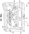
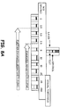
- FIG. 2A is a simplified block diagram of a portable assay reader 200 in accordance with one example embodiment of the present invention.
- Reader 200 includes a housing 202 having an opening 204 therein configured to receive the LFA 100 in a slot or holder 206.
- a laser 220 generates energy 120 directed to the test region of the LFA 100.
- the energy can be, for example, visible or near infrared light that is focused on the test region using an optional lens 222.
- visible or near infrared light directed at nanoparticles can cause heating of the nanoparticles. This is detected with a sensor 122 such as an infrared sensor.
- the results of the test can be displayed on a display 230 which can comprise for example, LCD display.
- the display can provide a quantitative output or a qualitative output such as a simple pass/fail indication.
- An optional user input 232 is provided.
- this input can be a single button allowing an operator to initialize a test, or can be a more complex input such as a numerical keypad or of a numeric keypad allowing an operator to update parameters such as threshold values used by the device 200.
- the input 232 can be an overlay on display 230 to provide a touchscreen.
- Operation of device 200 is controlled by electronic circuitry 240 as described below in more detail.
- This may include, for example, a microprocessor, analog-to-digital converters, I/O circuitry, etc.
- a power source 242 is provided.
- the power source 242 is a portable power source such as a battery or the like.
- the power source may optionally be rechargeable either through connection to another electrical source or using a solar cell or the like.
- device 200 includes input/output (I/O) circuitry 310 that is described below in more detail.
- I/O circuitry 310 allows data collected by the device 200 to be transmitted or otherwise provided to other devices. For example, test results can be collected and transmitted to a central location or cloud server for subsequent evaluation.
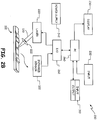
- Figure 2B is a simplified block diagram of assay reader 200 configured in a "bench top" configuration.
- a computer identified as PC is used to perform the testing.
- PC 260 couples to laser 220 and infrared sensor 122 through I/O circuitry 262.
- I/O circuitry 262 can include, for example, digital-to-analog converters, analog-to-digital converters, switchable outputs, etc.
- the PC 260 shown in Figure 2B will have more computing power than that is available in a portable device. This may allow additional testing or more advanced testing to be performed.
- the source 220 comprises a laser, for example a 532nm green laser (i.e. LRS-0532-PFM_00200-03, LaserGlow Technologies Inc).
- Focusing optics 222 can comprise for example a plano-convext focusing lens.
- a suitable infrared sensor includes an infrared camera (A20 or E30, FLIR Inc) or infrared sensor (MLX90614, Melexis).
- the present invention is not limited to this configuration.
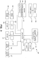
- FIG. 3 is a simplified block diagram of device 200 and includes a microprocessor 300 operating in accordance with instructions stored in a memory 302.
- Microprocessor 300 controls the energy source 220 by activating energy source power supply 302.
- the heating of the LFA (not shown in FIG. 3 ) is detected by heat sensor 122 that provides an output to an analog-to-digital converter 304.
- An optional strip sensor 306 is provided. Strip sensor 306 can be configured to detect the presence of LFA 100 in slot 206 thereby allowing the microprocessor 300 to activate the energy source 220 and begin the test.
- Figure 3 shows an optional recharge circuit 308 connected to power supply 242. This may allow the power supply 242 to be recharged, for example, using an external power source, a solar cell, a mechanical crank, etc.
- Input/output circuitry 310 is also illustrated coupled to microprocessor 300.
- This may include any type of input or output device including a display, keyboard or manual input, audible output, digital output such as a USB or Ethernet connection, an RF (radio frequency) or IR (infrared) input and/or output, a cellular data connection, an Ethernet connection, etc.
- Example RF connections include but are not limited to BLUETOOTH ® connections or other short distance communication techniques, WIFI connections, or others.
- Cellular phone connections allow the device to communicate using a cellular phone network for communicating data and/or providing optional voice communication.
- the data may include the test results and geographic information (GPS location) to collect spatiotemporal information on infectious diseases.
- I/O 310 allows data collected by device 200 to be sent to another location. For example, when used in the field, device 200 can transmit test results back to a central database. This transmission can be through any appropriate technique. For example, data can be sent through an Internet connection, over a cellular network, etc. The connection may require a physical wired connection or may occur wirelessly using WIFI, Bluetooth, etc. Additionally, the I/O can be used to update information stored in the memory 302. For example, programming instructions, calibration information or other data may be updated. The I/O 310 may also be used to communicate with an operator from a remote location using display 230 and/or input 232.
- a LFA 100 (not shown in FIG. 3 ) is placed within housing 202, for example through slot 204 (shown in FIG. 2 ).
- the test process is initiated by microprocessor 300 in response to a signal from the strip sensor 306, or some other trigger such as a manual input using input/output circuitry 310.
- an optional stepper motor 307 is provided and controlled by the microprocessor 300.
- the stepper motor 307 can be used to automate the movement of the LFA 100 within the device 200.
- the multiple strip sensors 306, or other configurations can be used if it is desired to monitor the location of the LFA 100 within the device 200.
- This causes the microprocessor 300 to apply power to the energy source 220 thereby heating the LFA 100.
- the heating response is sensed by sensor 122 and converted into a digital signal using an analog-to-digital signal converter 304. Based upon this digitized signal, the microprocessor 300 provides an output using input/output circuitry 310 that is indicative of the test results.
- Figure 3 shows a feedback sensor 303 that is arranged in the path of source 220 in order to sense the strength of the applied energy.
- the output from the feedback sensor 303 is provided to the processor 300 through an analog to digital converter 305.
- sensor 303 can be a light sensor to sense the intensity of the output from a laser 220. This information can be used to calibrate operation of the device and calibrate the sensed heating. Further, the feedback can be used for diagnostic purposes in order to detect a source 220 that is putting out a weak signal or has failed completely.
- Memory 302 is used by microprocessor for short and long-term storage of information.
- addressing information 320 of the device 200 can be stored in memory 302.
- This address may be, for example, an address that uniquely or semi-uniquely identifies the device 200 and may include, but is not limited to an Internet protocol (IP) address, a Mac address, or other address format.
- IP Internet protocol
- the memory 302 may also be used to store calibration information that can be used to calibrate the data received from sensor 122.
- the calibration information can be determined in any number of ways including, for example, during manufacture of the device, input using circuitry 310, or based upon a calibration performed using a LFA 100, for example, using calibration region 116 shown in Figure 1 . This calibration information can provide a baseline or other type of offset to the readings provided by the sensor 122.
- Memory 302 also includes operating instructions 324 which are used to control operation of the microprocessor 300.
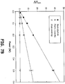
- Figures 4A and 4B are graphs which illustrate the heating response of LFA 100 when energy 120 is applied, T S .
- the amount of heating reaches a maximum indicated by R M .
- the response has a slope which begins at its steepest rise and slowly levels off to the maximum level R M .
- Microprocessor 300 operates as diagnostic circuitry by analyzing the heating response to the applied energy signal. For example, a simple threshold level can be used in which the maximum response is compared to a threshold level. This can be provided as an output, for example a "pass/fail" output based upon the comparison. Further, a quantitative output can be provided based upon the maximum response level. This quantitative output can illustrate the amount of gold nanoparticles that have been captured at the test location 114 (shown in FIG. 1 ). This can be correlated to, for example, the amount of antigen and therefore the progression of a disease in the patient.
- the diagnostics are based upon the profile of the response. For example, in FIGS. 4A and 4B , an initial slope of the response is illustrated. Based upon this initial slope, it is possible to extrapolate the value of R M without the necessity of allowing the heating to reach the maximum value. This technique can be used to increase the speed of the testing process. Further, this information can also be used to verify the value of R M detected by the sensor 122. For example, if the extrapolated value of R M differs significantly from the measured value of R M , it may be an indication of a failing component, a damaged test strip, or some other error in the measurement. Further, as discussed above, the calibration information can be used to improve the accuracy of the measurements. For example, the calibration information can provide a baseline response to which the response signal is compared. Thus, the response threshold levels can be adjusted based upon the calibration information.
- the energy source 220 can be any appropriate energy source.
- the energy source 220 comprises a laser.
- a variety of lasers are known in the art for use as a heat source and can be, for example, a continuous wave laser, pulsed wave laser or a reduced size laser. Thermal contrast sensitivity may be increased by using higher powered lasers and/or tuning the laser power for different concentrations of GNPs to extend the dynamic range.
- the laser can emit light in the visible range. Lasers may also be used that emit light in the near infrared region. Generally, the laser is selected and tuned to maximize the absorption within the nanoparticles while minimizing the interference from the background materials.
- the amount of laser power used in the LFA system can vary and is dependent on the components of the assay.
- the laser power was between about 5W and about 50 W (continuous wave laser).
- higher or lower energy levels may be used in other embodiments. For instance, lower total energy but higher energy density may be applied with pulsed laser. With the reduction of background absorption discussed below, higher laser power maybe used for further improved sensitivity and signal strength.
- the membrane, and backing include materials that have minimal light absorption. Background heating limits the ability to use higher energy to obtain higher signal strength. By selecting materials that have minimal light absorption, the background thermal reading can be reduced to ensure that the thermal detection is from the nanoparticles in the test region and not the materials of the assay system.
- the membrane in the LFA system is generally a porous material containing a plurality of interstices or pores. Liquid can flow through these interstices or pores generally by capillary action.
- the porous material can be made from natural or synthetic substances.
- Suitable porous materials for use in the LFA systems can include, for example, nitrocellulose, polyvinylidene fluoride (PVDF), polyethylene, nylon, cellulose acetate, polyester, polyethersulfone (PES), polysulfone and the like. Preferred embodiment uses the membrane that has the smallest light absorption. Other porous materials may also be used that are known in the art.
- a variety of backings are known in the art and mainly provide structural support for LFA. For thermal contrast detection, materials that have minimal light absorption are preferred as backing in the LFAs described herein. In one preferred embodiment, the backing can be made of glass or plastic (for instance polystyrene).
- Sample pad can be made from a variety of materials including, for example, polyester, polyacrylic, other polylmeric materials or glass fiber. Conjugate pad and absorbent pad can be made from, for example, cellulosic materials or the like.
- the nanoparticles can comprise a variety of materials, shapes and sizes.
- the nanoparticles can be gold nanoparticles, silver nanoparticles, copper nanoparticles, platinum nanoparticles, aluminum nanoparticles, cadmium nanoparticles, composite particles, i.e. silver and gold, graphene nanoparticles and the like.
- the LFA assay system includes gold nanoparticles.
- Other types of nanoparticles may also be employed and are within the scope of this description.
- a combination of two or more types of nanoparticles may be used. These may be used to identify multiple analytes or to amplify or enhance the signal.
- the nanoparticles can include a range of sizes and generally must be able to travel through the membrane.
- the diameter of the nanoparticles can be range from 10nm to 200 nm.
- the selection and optimization of nanoparticle size depends partly on the energy absorption.
- the physical phenomenon named plasmon resonance enhances the efficiency of optical absorption and therefore heat generation.
- Gold nanoparticles up to about 100nm in diameter can be used. Larger sizes are available and may also be used and are included in the scope of the present invention.
- nanoparticles can be used in the LFA system described herein and all are within the scope of the invention.
- the nanoparticles can be, for example, nanospheres, nanorods, nanoshells, nanocubes, nanourchins, nanopyramids, nanostars, and the like.
- the nanoparticles are nanospheres, nanorods and/or nanoshells. Any of these shapes of nanoparticles can be used.
- the nanoparticles with the highest optical absorption efficiency and that can be functional in the assay with regards to other properties are preferable. For particles with nonspherical shape, effective radius (sphere with equivalent volume) may be used to calculate the absorption efficiency.
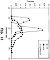
- the polydispersity of the GNPs used in existing LFAs are not well controlled, as seen in Figs. 12A-C and 13 for CrAg and hCG dipsticks.
- Better control of polydispersity leads to more uniform nanoparticles size distribution. This can lead to smaller standard deviations for thermal contrast detection, and therefore improves the signal stability and consistency.
- More uniform nanoparticles may also give higher optical absorption and heat generation. For instance, GNPs with different sizes have peak absorption at different wavelengths. For polydispersed GNP population, less GNPs will generate heat at peak absorption wavelength and thus reducing the amount of heat generated.
- well-dispersed nanoparticles of uniform size are preferable to nanoparticle clusters.
- the nanoparticles can lead to less uniform absorption by the nanoparticles.
- the nanoparticles may, optionally, be coated to decrease clustering thereby increasing uniformity of absorption.
- the coating if present, preferably does not reduce the absorption within the nanoparticles.
- the size distribution of the nanoparticles can vary. In some embodiments, at least about 60 percent of the nanoparticles are within +/-10nm of the mean diameter of the nanoparticles. Preferably, at least about 70 percent of the nanoparticles are within about +/-5nm of the mean diameter of the nanoparticles. More preferably, at least about 70 percent of the nanoparticles are within about +/-3nm of the mean diameter of the nanoparticles. Even more preferably, at least about 75 percent of the nanoparticles are within about +/-3nm of the mean diameter of the nanoparticles. Nanoparticles outside of these ranges are also within the scope of the invention.
- the amount or concentration of nanoparticles used in an LFA system can vary depending on the specific assay, the specific nanoparticles, the analyte binding molecules and the like. Generally, the amount of nanoparticles can be on the order of about 1-100 ⁇ g. Nanoparticle amounts outside of this range may also be used and are within the scope of this invention. For one embodiment, CrAg assay uses about 4 ⁇ g of GNPs per LFA. The amount of nanoparticles used can be higher or lower than the specified range depending on binding affinity of the binding molecules, concentration range of target analyte in the patient samples, among other factors
- Analytes in a variety of samples may be determined and generally can be any type of liquid sample.
- the samples may be biological samples, chemical samples, environmental samples, food samples and the like.
- Biological samples can include, for example, blood, plasma, serum, urine, sweat, bile, cerebrospinal fluid, fecal material, vaginal fluids, saliva and the like. Other biological samples may also be analyzed.
- the sample with the analyte may be used directly or diluted using diluent.
- Diluent can be a variety of solutions and are generally known in the art. In an exemplary embodiment, the diluent is a saline solution.
- a target analyte can be a protein, peptide, nucleic acid, hapten, chemical and the like.
- Analytes can also include therapeutic drugs, drugs of abuse, hormones, vitamins, glucose proteins, antibodies, steroids, bacteria or bacterial infection, fungi, viruses, parasites, components and products of bacteria, allergens, antigens and the like.
- An analyte can also include derivatives or metabolites of the compound of interest.
- the analyte can be associated with a disease, for example, malaria, TB and the like. In other embodiments, the analyte can be associated with a physiological or pathological condition, for example, pregnancy.
- analytes include Cryptococcal antigen (CrAg), malarial antigen, Tuberculosis antigen, human chorionic gonadotropin (hCG), human luteinizing hormone (hLH), human follicle stimulating hormone (hFSF), prostate speific antigen (PSA), hepatitis B surface antigen, hepatitis B antibodies, HIV antigen, Streptococcus A, Staphylococcus bacteria, STDs, P. Falciparum, Fever panel and the like.
- CrAg Cryptococcal antigen
- hCG human chorionic gonadotropin
- hLH human luteinizing hormone
- hFSF human follicle stimulating hormone
- PSA prostate speific antigen
- the analyte binding molecules and the capture molecules can be any molecule that is capable of binding the target analyte.
- the analyte binding molecules and the capture molecules are biological macromolecules, for example, antibodies or parts of antibodies. These molecules can also be receptors, ligands, polynucleotides, polypeptides, glycopeptides, lipoproteins, nucleoproteins, nucleic acid, aptamer, and the like.
- the analyte binding molecules and the capture molecules are antibodies.
- the analyte binding molecules are the same as the capture molecules. In other embodiments, the analyte binding molecules are different than the capture molecules.
- conjugation chemistry that allow improved stability at high temperatures, high or low humidities and/or radiative conditions are preferable.
- Chemical binding refers to the use of chemical functional groups and/or molecules that link the particles to the analyte binding molecule.
- An example is the placement of carboxylic acids on the surface of the particles to allow for linkage to amine functional groups on an antibody through a carbodiimide mediated molecule.
- Conjugation may involve passive adsorption. Passive adsorption is known in the art and disclosed, for example in US 2010/0136566 incorporated herein by reference.
- a variety of liquid dispensing and spray technologies are known in the art for deposition of the capture molecules to the membrane. Any of these may be used and spray technologies that lead to better absorption and stability of the capture molecules are preferable. Nanoparticles conjugated to analyte binding molecules may also be sprayed onto the conjugate pad. In an exemplary embodiment, a variety of liquid dispensing instruments from BioDotTM may be used for these purposes.
- the present description also includes a method of detecting an analyte in a sample.
- the LFA analytical sensitivity can be substantially improved, potentially >10,000-fold over visual detection methods by the use of thermal contrast technology described herein.
- the method includes contacting a sample with the sample pad and allowing the liquid to flow through the membrane by capillary action.
- Nanoparticles conjugated with the analyte binding molecules move within the membrane through capillary action in response to the sample application.
- the target analyte binds to the conjugated nanoparticles.
- the nanoparticle/analyte complex stops moving though the membrane when the capture molecule in the test region recognizes and binds the nanoparticle/analyte complex. This leads to accumulation of the nanoparticle/analyte complex at the test zone or region of the LFA.
- the method further includes using the thermal contrast reader to detect and quantitate the amount of analyte in the test region by first exposing the test region to an energy source such as a laser and then measuring the heat generated from the test strip by a sensor.
- the output generated by the sensor is indicative of the presence and/or amount of the target analyte.
- the method can also include detecting multiple analytes. Multiple analytes can be detected by having multiple test regions, wherein each test region has different capture molecules. Thus, the first nanoparticle/analyte complex binds to test region 1 having a first capture molecule that binds the first analyte , wherein the second nanoparticle/analyte complex binds to test region 2 having a second capture molecule that binds the second analyte and not the first analyte. In this manner, the LFA system can be extended to identify multiple analytes by configuring to include multiple test regions. Multiple analytes may also be detected using multiple nanoparticles having differing starting positions.
- the nanoparticles may have different conjugates and different analyte binding molecules. These can be tuned to have different flows through the membrane.
- the multiple analytes may be in the same sample or different samples. In some embodiments, multiple analytes may be tested in the same test region. The detection of the multiple analytes results in the identification, preferably with a quantitative amount of analyte, for each of the analytes in the corresponding test region. In some embodiments, the multiple analytes may also be detected and/or quantified cumulatively in one test region. For example, using different particles that absorb at different laser wavelengths allows multiplexing using laser excitation with corresponding wavelengths.
- the method can also include amplification of the signals through the use of a secondary controlled flow of different nanoparticles.
- the signal from a LFA with primary gold nanoparticles can be amplified by the use of silver staining or secondary binding nanoparticles.
- the gold nanoparticles can act as a nucleation site for the growth of a silver shell on the surface.
- the secondary nanoparticle binds to the first particle that captures the target analyte to amplyify the signal.
- the present method also includes quantitation of the amount of analyte present in the test region.
- the measurement of the thermal change of the membrane can be correlated to the amount of analyte present in the test region.
- the LFA system can advantageously provide not only the presence or absence of analyte but also provides the level of analyte present in the membrane and consequently the sample. This is particularly advantageous for determining the extent of the disease, infection or condition in a patient.
- SAR absorption rate
- SAR can be used to determine the amount of analyte present in the test region.
- SAR is in effect the Q in Equation 1 above. It relates to the amount of heat energy in W/m 3 given off by the nanoparticles once they have been activated by an energy source such as a laser. As shown in Equation 1, it is directly proportional to the laser fluence and the number of nanoparticles which then relates directly to the amount of antigen in the analyte.
- the LFAs can also be archived for future analysis. Unlike other detection methods, there is no loss of signal using the thermal contrast system. In fluorescence measurements, organic fluorophores experience photobleaching. In some colorimetric measurements, the dyes may lose their signal over time through photodestruction. Thermal contrast readings conducted after two weeks of conducting the assay can be nearly identical. This advantageously allows for processing point-of-care LFAs in the field and referral to a central lab to process the same LFA system for thermal contrast readings. In other words, the analyte signal does not have to be measured immediately after the sample is run. The signal may be measured multiple times, for example, immediately after the assay is complete and also at a later time.
- the method can also include exposing the test region to the energy source and measuring the analyte in the test region after twelve hours, 24 hours or more after contacting the assay strip with the sample.
- Cryptococcosis is among the leading causes of death among all AIDS-related opportunistic infections and is the most common cause of meningitis in adults in Africa causing >500,000 deaths worldwide annually.
- Cryptococcal meningitis is classically diagnosed by a combination of culture, India ink, or CrAg testing with semi-quantification by serial two-fold dilutions (i.e. CrAg titer, defined as the last positive test when performing two-fold serial dilutions).
- the present description includes a method for detection and quantification of the CrAg antigen.
- the method includes contacting a sample with the sample pad and allowing the liquid to flow through the membrane by capillary action. Nanoparticles conjugated with the CrAg binding molecules move within the membrane through capillary action in response to the sample application. When present, the CrAg binds to the conjugated nanoparticles. The nanoparticle/CrAg complex stops moving though the membrane when the capture molecule in the test region recognizes and binds the nanoparticle/CrAg complex. This leads to accumulation of the nanoparticle/CrAg complex at the test region of the LFA.
- the thermal contrast system can be used to detect and quantitate the amount of CrAg in the test region by first exposing the test region to a heat source such as a laser and then measuring the heat generated from the test strip by a heat sensor.
- the present description includes a method for detection and quantification of the hCG antigen.
- the method includes contacting a sample with the sample pad and allowing the liquid to flow through the membrane by capillary action. Nanoparticles conjugated with the hCG binding molecules move within the membrane through capillary action in response to the sample application. When present, the hCG binds to the conjugated nanoparticles. The nanoparticle/ hCG complex stops moving though the membrane when the capture molecule in the test region recognizes and binds the nanoparticle/ hCG complex. This leads to accumulation of the nanoparticle/ hCG complex at the test region of the LFA.
- the thermal contrast system can be used to detect and quantitate the amount of hCG in the test region by first exposing the test region to a heat source such as a laser and then measuring the heat generated from the test strip by a heat sensor.
- the present description includes a method for detection and quantification of the malaria antigen.
- the method includes contacting a sample with the sample pad and allowing the liquid to flow through the membrane by capillary action. Nanoparticles conjugated with the malaria antigen binding molecules move within the membrane through capillary action in response to the sample application. When present, the malaria antigen binds to the conjugated nanoparticles. The nanoparticle/malaria antigen complex stops moving though the membrane when the capture molecule in the test region recognize and bind the nanoparticle/malaria antigen complex. This leads to accumulation of the nanoparticle/malaria antigen complex at the test region of the LFA.
- the thermal contrast system can be used to detect and quantitate the amount of malaria antigen in the test region by first exposing the test region to a heat source such as a laser and then measuring the heat generated from the test strip by a heat sensor.
- the present description includes a method for detection and quantification of the TB antigen.
- the method includes contacting a sample with the sample pad and allowing the liquid to flow through the membrane by capillary action. Nanoparticles conjugated with the TB antigen binding molecules move within the membrane through capillary action in response to the sample application. When present, the TB antigen binds to the conjugated nanoparticles. The nanoparticle/ TB antigen complex stops moving though the membrane when the capture molecule in the test region recognizes and binds the nanoparticle/TB antigen complex. This leads to accumulation of the nanoparticle/TB antigen complex at the test region of the LFA.
- the thermal contrast system can be used to detect and quantitate the amount of TB antigen in the test region by first exposing the test region to a heat source such as a laser and then measuring the heat generated from the test strip by a heat sensor.
- GNP Gold nanoparticle
- the thermal contrast versus visual contrast of GNPs in solution was compared.
- a series of different concentrations of GNPs were prepared. 10 ⁇ L of the GNP solution was placed on a microscope slide. For visual analysis, a picture was taken by a digital camera and analyzed later with Image J.
- the GNP solution was irradiated with laser (0.5W, 532nm) and the temperature change was recorded by an infrared camera.
- thermal contrast for detection can improve the overall analytical sensitivity by 100-fold ( Fig. 5 ).
- the thermal contrast of GNPs was also compared with standard optical density measurement using a standard micro-volume plate reader, the principle of which is widely used in microfluidic EL1SA. With the same sample volume (10 ⁇ L), the thermal contrast displayed 50-fold improvement over the optical density measurement. Further improvement in thermal contrast sensitivity can be possible by using higher powered lasers and/or tuning the laser power for different concentrations of GNPs to extend the dynamic range of thermal contrast. Importantly, by tuning laser wavelength to a higher absorbing nanoparticle (gold nanorod) we may also be able to increase the sensitivity.
- thermal contrast versus colorimetric detection i.e. visual contrast
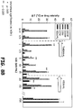
- LFAs for detecting cryptococcal antigen (CrAg) obtained from Immy, Inc. and described in Qin et al. Angewandte Chemie 2012 .
- Thermal contrast imaging of LFAs Cryptococcal antigen LFA (Immy, Inc. Norman, OK), which was FDA-approved in July 2011, detects the capsular polysaccharide antigens of Cryptococcus species complex (Cryptococcus neoformans and Cryptococcus gatlii ) in serum and cerebrospinal fluid (CSF).
- a serum sample from a patient with cryptococcal meningitis had 2-fold serial dilutions performed to assess the limits of detection, as the CrAg titer.
- the test was conducted following the manufacturer's instructions. Thermal contrast was performed by irradiating the test line by laser for 1 minute. An infrared camera recorded temperature change. Three spots on each horizontal test band were irradiated and the average maximum temperature change was measured. At each concentration, three separate LFA dipsticks were run. The results are shown in Fig. 6 .
- GNP droplets For the GNP droplets, images were taken by a digital camera. The dipsticks were scanned by a flatbed scanner (Model: Visioneer Onetouch 7400). The mean grey intensity for regions of interest (ROI). i.e. droplet and the test band for dipsticks, was analyzed. The same volume of GNP solution (10 ⁇ L) was also measured by a spectrophotometer at 530nm, with a Take3 micro-volume plate and Synergy HT Multi-Mode Microplate Reader (BioTek, Winooski, VT).
- ROI regions of interest
- the thermal contrast ( ⁇ T signal ) and nanoparticle concentrations are normalized.
- gold nanorods were about one order of magnitude more efficient in heat generation than the gold nanospheres and nanoshells ( Fig 7A inset).
- current LFAs i.e. thin nitrocellulose membranes with thick backing material
- use of low absorbing i.e.
- high transmitting or reflective backing materials such as plastic or glass
- I laser intensities
- Substrate absorption A blank dipstick and plastic and glass cover glasses were irradiated with 532nm laser for 1 minute each. The temperature change during laser irradiation was measured by infrared camera and the maximum temperature change determined. (See Fig. 7B ) Combining higher absorbing nanoparticles and low absorbing LFA backing materials can increase the sensitivity. It is worth noting that the gold nanorod may absorb efficiently at different wavelength than the gold nanosphere.
- a 1000-fold further increase in thermal contrast can be produced by increasing the power density by 100 times (i.e., increase in laser power from 0.01 to 1 W) and using a nanoparticle with a 10-fold increase in absorption (C abs ). Higher laser powers can be used by reducing background absorption discussed above.
- the analytical sensitivity of the assays can be improved by about 10,000 fold, considering the over 10 fold improvement shown and 1000 fold improvement predicted above over visual detection methods using the modifications described here.
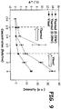
- hCG pregnancy test
- the presence of hCG (pregnancy test) in a sample was tested using a LFA with the GNPs.
- the hCG LFA was purchased from Fisher Scientific (Sure-Vue Serum/Urine hCG test kit).
- thermal contrast showed enhanced sensitivity to the presence of hCG relative to visual detection.
- the use of thermal contrast showed a 20-fold increase in the limit of detection.
- Malaria LFA was purchased from Alere Inc (BinaxNOWTM malaria test).
- thermal contrast showed enhanced sensitivity to the presence of the malaria antigen relative to visual detection.
- the use of thermal contrast showed an 8-fold increase in the limit of detection.
- TB LFA was manufactured by Alere Inc (DetermineTM TB LAM rapid test). The results are shown in Table 1. Thermal contrast detects a majority of visually negative TB LFAs (i.e. false negatives) based on reference standard of a sputum culture. TABLE 1 Method Ratio Detected Percent Detected TB-LAM LFA - visual 0/39 0 TB-LAM LFA - thermal 22/39 56 Sputum Culture 39/39 100
- Fig. 10A shows the temperature change over an extended period of time.
- Fig. 10B illustrates the change in temperature in the first 20 seconds.
- thermal contrast can be conducted by calculating the SAR. This enables the measurement at an earlier time to minimize interference. Specifically, heat addition over time leads to diffusion in a material. If the heat can be added very quickly such that diffusion is minimized, then the rate of temperature change is related entirely to the SAR (or Q in Equation 1) and therefore can more directly capture the presence of the GNPs and thus antigen in the test. This may allow the use of a pulsed laser.
- Fig. 11 illustrates the results from an experiment in using hCG as described above in Example 4 except the SAR was determined instead of the temperature change. As can be seen, SAR can be used for detection of analytes without a loss of sensitivity or accuracy.
- the nanoparticles were made as described in Example 1 using the method of Frens and analyzed for dispersity.
- the synthesized GNPs are more evenly dispersed than the GNPs in the dipsticks.
- Figure 13 is a quantification of the results seen in the TEM images of Figure 12 . Specifically, the counts of GNPs of different sizes are added and the graph illustrates that there is a much broader distribution within the existing dipsticks vs. those synthesized by the method of Frens.
Claims (5)
- Lecteur d'échantillons à contraste thermique (200) comprenant une source d'énergie (220), un capteur thermique (122), un circuit d'E/S (310) et une ouverture (204) destinée à recevoir une bande d'échantillon (100), le lecteur (200) étant configuré pour convertir les résultats du capteur thermique en un signal de sortie lors de l'activation de la source d'énergie (200) sur la région de test (114) de la bande d'échantillon, et dans lequel le capteur thermique (122) est un capteur infrarouge (122) configuré pour mesurer le contraste thermique dans la région de test (114) de la bande d'échantillon (100).
- Lecteur selon la revendication 1, dans lequel la source d'énergie (220) est un laser (220).
3 - Lecteur selon la revendication 1, dans lequel la région de test (114) de la bande d'échantillon (100) comprend des nanoparticules.
- Lecteur selon la revendication 1, dans lequel le lecteur (200) est un dispositif de table ou un dispositif portatif.
- Lecteur selon la revendication 1, dans lequel le signal de sortie est transmis à un autre dispositif par l'intermédiaire d'une connexion filaire ou d'une connexion sans fil.
Priority Applications (2)
| Application Number | Priority Date | Filing Date | Title |
|---|---|---|---|
| EP17204410.9A EP3321666B1 (fr) | 2012-01-31 | 2013-01-30 | Dosage de contraste thermique et lecteur |
| PL13706780T PL2810052T3 (pl) | 2012-01-31 | 2013-01-30 | Test i czytnik z kontrastem termicznym |
Applications Claiming Priority (2)
| Application Number | Priority Date | Filing Date | Title |
|---|---|---|---|
| US201261593036P | 2012-01-31 | 2012-01-31 | |
| PCT/US2013/023839 WO2013116333A2 (fr) | 2012-01-31 | 2013-01-30 | Analyse à contraste thermique et lecteur |
Related Child Applications (1)
| Application Number | Title | Priority Date | Filing Date |
|---|---|---|---|
| EP17204410.9A Division EP3321666B1 (fr) | 2012-01-31 | 2013-01-30 | Dosage de contraste thermique et lecteur |
Publications (2)
| Publication Number | Publication Date |
|---|---|
| EP2810052A2 EP2810052A2 (fr) | 2014-12-10 |
| EP2810052B1 true EP2810052B1 (fr) | 2017-12-06 |
Family
ID=47754956
Family Applications (2)
| Application Number | Title | Priority Date | Filing Date |
|---|---|---|---|
| EP17204410.9A Active EP3321666B1 (fr) | 2012-01-31 | 2013-01-30 | Dosage de contraste thermique et lecteur |
| EP13706780.7A Active EP2810052B1 (fr) | 2012-01-31 | 2013-01-30 | Analyse à contraste thermique et lecteur |
Family Applications Before (1)
| Application Number | Title | Priority Date | Filing Date |
|---|---|---|---|
| EP17204410.9A Active EP3321666B1 (fr) | 2012-01-31 | 2013-01-30 | Dosage de contraste thermique et lecteur |
Country Status (11)
| Country | Link |
|---|---|
| US (1) | US9651508B2 (fr) |
| EP (2) | EP3321666B1 (fr) |
| JP (1) | JP2015509201A (fr) |
| KR (1) | KR20140127275A (fr) |
| CN (2) | CN104471382B (fr) |
| AP (1) | AP2014007834A0 (fr) |
| BR (1) | BR112014018563A2 (fr) |
| ES (2) | ES2661870T3 (fr) |
| IN (1) | IN2014MN01698A (fr) |
| PL (1) | PL2810052T3 (fr) |
| WO (1) | WO2013116333A2 (fr) |
Families Citing this family (23)
| Publication number | Priority date | Publication date | Assignee | Title |
|---|---|---|---|---|
| US20150010441A1 (en) * | 2013-07-02 | 2015-01-08 | Elana M. Kahn | Electronic Pregnancy Test Device |
| US20160169887A1 (en) * | 2014-12-15 | 2016-06-16 | Church & Dwight, Co., Inc. | Systems, devices and methods for a lateral flow assay with solution enhancement |
| US10001449B2 (en) | 2014-12-15 | 2018-06-19 | Church & Dwight Co., Inc. | Systems, devices and methods for a hydroscopic based lateral flow assay |
| US10094823B2 (en) | 2015-01-23 | 2018-10-09 | Tokitae Llc | Photothermal spectroscopy assay readers, and related assay kits and methods |
| US9625385B2 (en) * | 2015-02-24 | 2017-04-18 | Tokitae Llc | Photothermal spectroscopy systems for offset synchronous testing of flow assays and methods of using same |
| CN105242047B (zh) * | 2015-10-31 | 2017-05-31 | 中国农业科学院油料作物研究所 | 黄曲霉毒素b1氧化石墨烯免疫层析试纸条及其应用 |
| CN105259094B (zh) * | 2015-11-20 | 2018-11-09 | 厦门大学 | 基于红外热像的免疫层析试条样品液流速检测系统与方法 |
| US10983119B2 (en) | 2016-01-25 | 2021-04-20 | General Electric Company | Device for rapid diagnostic tests to detect antigens with improved sensitivity |
| US10132743B2 (en) * | 2016-01-25 | 2018-11-20 | General Electric Company | Fixed optics photo-thermal spectroscopy reader and method of use |
| CN110191756B (zh) * | 2016-11-17 | 2021-09-21 | 伯乐实验室有限公司 | 用于回收和分析粒子的系统和方法 |
| KR101996815B1 (ko) * | 2017-07-07 | 2019-07-05 | 한국과학기술연구원 | 적외선을 흡광 및 발광하는 진단용 포획제-나노입자 복합체 및 이를 이용하는 현장용 진단키트 |
| WO2019068045A1 (fr) * | 2017-09-29 | 2019-04-04 | Leica Biosystems Imaging, Inc. | Balayage en z fixe en deux et trois dimensions |
| US10228321B1 (en) * | 2017-11-21 | 2019-03-12 | Saudi Arabian Oil Company | System and method for infrared reflection avoidance |
| CA2986532C (fr) * | 2017-11-23 | 2022-06-28 | Pouya Rezai | Systeme et methode d'analyse photothermique de tests de dosage immunologique |
| US10830760B2 (en) | 2017-12-20 | 2020-11-10 | General Electric Company | Device for rapid detection of tuberculosis-lipoarabinomannan (TB-LAM) with enhanced sensitivity |
| US10837962B2 (en) | 2017-12-20 | 2020-11-17 | General Electric Company | Method and associated device for rapid detection of target biomolecules with enhanced sensitivity |
| CN108375678A (zh) * | 2018-02-09 | 2018-08-07 | 上海格荣生物科技有限公司 | 检测前列腺肿瘤抗原的试纸条及方法 |
| CN108680508A (zh) * | 2018-05-18 | 2018-10-19 | 中国检验检疫科学研究院 | 一体式光热效应检测仪 |
| GB2591614B (en) * | 2018-06-22 | 2023-05-10 | Oova Inc | Methods, devices, and systems for detecting analyte levels |
| WO2020045625A1 (fr) * | 2018-08-31 | 2020-03-05 | 富士フイルム株式会社 | Kit d'immunochromatographie et méthode de détection de mycobacterium tuberculosis |
| WO2021209576A1 (fr) * | 2020-04-16 | 2021-10-21 | Senova Gesellschaft für Biowissenschaft und Technik mbH | Dosage à écoulement latéral |
| WO2021231659A1 (fr) * | 2020-05-12 | 2021-11-18 | Sapphire Biotech, Inc. | Test d'anticorps neutralisants et traitement |
| CN114280047B (zh) * | 2021-12-28 | 2024-01-05 | 江南大学 | 一种检测小分子化合物的比色-光热双模式试纸条及其制备方法 |
Family Cites Families (37)
| Publication number | Priority date | Publication date | Assignee | Title |
|---|---|---|---|---|
| US4094647A (en) | 1976-07-02 | 1978-06-13 | Thyroid Diagnostics, Inc. | Test device |
| NL7807532A (nl) | 1978-07-13 | 1980-01-15 | Akzo Nv | Metaal-immunotest. |
| US5073484A (en) | 1982-03-09 | 1991-12-17 | Bio-Metric Systems, Inc. | Quantitative analysis apparatus and method |
| IT1160788B (it) | 1983-04-15 | 1987-03-11 | Belleli Spa | Supporto di fascio tubiero in scambiatori di calore |
| US5514602A (en) | 1986-06-09 | 1996-05-07 | Ortho Diagnostic Systems, Inc. | Method of producing a metal sol reagent containing colloidal metal particles |
| CA1303983C (fr) | 1987-03-27 | 1992-06-23 | Robert W. Rosenstein | Essai en phase solide |
| US4857453A (en) | 1987-04-07 | 1989-08-15 | Syntex (U.S.A.) Inc. | Immunoassay device |
| EP1248112A3 (fr) | 1987-04-27 | 2004-08-25 | Inverness Medical Switzerland GmbH | Dispositif d'essai immunochromatographique à liaison spécifique |
| US5120643A (en) | 1987-07-13 | 1992-06-09 | Abbott Laboratories | Process for immunochromatography with colloidal particles |
| AU2684488A (en) | 1988-06-27 | 1990-01-04 | Carter-Wallace, Inc. | Test device and method for colored particle immunoassay |
| US6352862B1 (en) | 1989-02-17 | 2002-03-05 | Unilever Patent Holdings B.V. | Analytical test device for imuno assays and methods of using same |
| US5252496A (en) | 1989-12-18 | 1993-10-12 | Princeton Biomeditech Corporation | Carbon black immunochemical label |
| US6136610A (en) | 1998-11-23 | 2000-10-24 | Praxsys Biosystems, Inc. | Method and apparatus for performing a lateral flow assay |
| CA2366802A1 (fr) | 2001-01-17 | 2002-07-17 | Bayer Corporation | Methode et appareil permettant d'utiliser les releves infrarouges pour detecter les erreurs d'identification d'une bande d'essai diagnostique utilisee dans un spectrometre a reflectance |
| DK1432786T3 (da) | 2001-09-06 | 2009-10-26 | Rapid Micro Biosystems Inc | Hurtig detektion af replikerede celler |
| US8367013B2 (en) | 2001-12-24 | 2013-02-05 | Kimberly-Clark Worldwide, Inc. | Reading device, method, and system for conducting lateral flow assays |
| CA2471625A1 (fr) * | 2001-12-27 | 2003-07-24 | Inverness Medical Switzerland Gmbh | Nouveau dispositif, systeme et procede pour la detection par fluorescence |
| US7371582B2 (en) | 2002-01-23 | 2008-05-13 | Boditechmed Inc. | Lateral flow quantitative assay method and strip and laser-induced fluorescence detection device therefor |
| US7314763B2 (en) | 2002-08-27 | 2008-01-01 | Kimberly-Clark Worldwide, Inc. | Fluidics-based assay devices |
| US20040180369A1 (en) * | 2003-01-16 | 2004-09-16 | North Carolina State University | Photothermal detection of nucleic acid hybridization |
| US20040197819A1 (en) | 2003-04-03 | 2004-10-07 | Kimberly-Clark Worldwide, Inc. | Assay devices that utilize hollow particles |
| CA2522282A1 (fr) * | 2003-04-15 | 2004-10-28 | Optiscan Biomedical Corporation | Element d'echantillonnage utilise dans l'analyse d'un materiau |
| KR100639776B1 (ko) | 2004-01-05 | 2006-10-27 | 바이오메드포토닉스 주식회사 | 측방 유동 정량 검정 방법 및 이를 위한 스트립과 레이저유발 표면형광 검출 장치 및 소형 스캐너 |
| US20080032420A1 (en) * | 2004-03-30 | 2008-02-07 | Lambert James L | Surface Enhanced Raman Scattering and Multiplexed Diagnostic Assays |
| US8128871B2 (en) | 2005-04-22 | 2012-03-06 | Alverix, Inc. | Lateral flow assay systems and methods |
| US8153444B2 (en) | 2005-10-13 | 2012-04-10 | Auric Enterprises, Llc | Immuno gold lateral flow assay |
| US20090155811A1 (en) | 2006-01-27 | 2009-06-18 | Oxonica, Inc. | Lateral Flow Immunoassay With Encapsulated Detection Modality |
| RU2008151166A (ru) | 2006-05-24 | 2010-06-27 | Конинклейке Филипс Электроникс Н.В. (Nl) | Устройство получения изображения объекта для формирования объединенного температурного и люминесцентного трехмерного изображения |
| US8108030B2 (en) * | 2006-10-20 | 2012-01-31 | Board Of Regents, The University Of Texas System | Method and apparatus to identify vulnerable plaques with thermal wave imaging of heated nanoparticles |
| WO2008067079A2 (fr) | 2006-10-20 | 2008-06-05 | Cardiospectra, Inc. | Procédé et appareil pour identifier des plaques vulnérables avec imagerie d'onde thermique de nanoparticules chauffées |
| US20080102473A1 (en) | 2006-10-31 | 2008-05-01 | Fouquet Julie E | Method and system to improve contrast in lateral flow assay |
| EP1933147B1 (fr) | 2006-12-11 | 2011-08-17 | AraGen Biotechnology Co. Ltd. | Détection rapide immunochromatographique par amplification du signal d'or colloïdal |
| WO2009152209A2 (fr) | 2008-06-10 | 2009-12-17 | Rapid Pathogen Screening, Inc. | Test de détection d'analyte visuel/par fluorescence combiné |
| CN101368907A (zh) * | 2008-07-14 | 2009-02-18 | 马义才 | 一种基于cmos图像传感器的量子点标记试条定量检测系统 |
| WO2010065781A2 (fr) | 2008-12-03 | 2010-06-10 | Abaxis, Inc. | Dosage à bande d'écoulement latéral avec un conjugué immobilisé |
| US8105843B2 (en) | 2009-11-04 | 2012-01-31 | Buchanan Thomas M | Methods and devices to enhance sensitivity and evaluate sample adequacy and reagent reactivity in rapid lateral flow immunoassays |
| US20130123121A1 (en) | 2010-11-22 | 2013-05-16 | The University Of Chicago | Methods and/or Use of Oligonucleotide-Bead Conjugates for Assays and Detections |
-
2013
- 2013-01-30 IN IN1698MUN2014 patent/IN2014MN01698A/en unknown
- 2013-01-30 JP JP2014555670A patent/JP2015509201A/ja active Pending
- 2013-01-30 BR BR112014018563A patent/BR112014018563A2/pt not_active IP Right Cessation
- 2013-01-30 ES ES13706780.7T patent/ES2661870T3/es active Active
- 2013-01-30 EP EP17204410.9A patent/EP3321666B1/fr active Active
- 2013-01-30 US US14/375,294 patent/US9651508B2/en active Active
- 2013-01-30 AP AP2014007834A patent/AP2014007834A0/xx unknown
- 2013-01-30 WO PCT/US2013/023839 patent/WO2013116333A2/fr active Application Filing
- 2013-01-30 CN CN201380016094.5A patent/CN104471382B/zh active Active
- 2013-01-30 KR KR1020147023705A patent/KR20140127275A/ko not_active Application Discontinuation
- 2013-01-30 CN CN201710664648.2A patent/CN107505465B/zh active Active
- 2013-01-30 ES ES17204410T patent/ES2816061T3/es active Active
- 2013-01-30 EP EP13706780.7A patent/EP2810052B1/fr active Active
- 2013-01-30 PL PL13706780T patent/PL2810052T3/pl unknown
Also Published As
| Publication number | Publication date |
|---|---|
| PL2810052T3 (pl) | 2018-07-31 |
| EP2810052A2 (fr) | 2014-12-10 |
| CN107505465A (zh) | 2017-12-22 |
| WO2013116333A2 (fr) | 2013-08-08 |
| JP2015509201A (ja) | 2015-03-26 |
| CN104471382B (zh) | 2017-08-25 |
| US20140377770A1 (en) | 2014-12-25 |
| US9651508B2 (en) | 2017-05-16 |
| ES2661870T3 (es) | 2018-04-04 |
| IN2014MN01698A (fr) | 2015-05-29 |
| WO2013116333A3 (fr) | 2013-11-07 |
| EP3321666A1 (fr) | 2018-05-16 |
| AP2014007834A0 (en) | 2014-07-31 |
| BR112014018563A2 (pt) | 2017-08-22 |
| CN104471382A (zh) | 2015-03-25 |
| EP3321666B1 (fr) | 2020-06-17 |
| KR20140127275A (ko) | 2014-11-03 |
| ES2816061T3 (es) | 2021-03-31 |
| CN107505465B (zh) | 2020-01-14 |
Similar Documents
| Publication | Publication Date | Title |
|---|---|---|
| EP2810052B1 (fr) | Analyse à contraste thermique et lecteur | |
| US10816492B2 (en) | Lateral flow assays with thermal contrast readers | |
| US20210293793A1 (en) | Interactive test device and apparatus with timing mechanism | |
| Hwang et al. | Application of a SERS-based lateral flow immunoassay strip for the rapid and sensitive detection of staphylococcal enterotoxin B | |
| AU2010236424B2 (en) | Diagnostic devices and related methods | |
| KR101926447B1 (ko) | 표면-증강 라만 산란 기반의 고감도 측면유동 면역분석용 스트립 및 이를 이용한 검출방법 | |
| EP3077798B1 (fr) | Procédé de réduction de la variabilité d'un analyseur au moyen d'une cible de normalisation | |
| JP2007024883A (ja) | 標識粒子と相互作用するナノ構造又はナノ粒子を含む基材による、金及び銀ナノ粒子を利用するpoctデバイスの感度の向上法 | |
| US20230251202A1 (en) | High-sensitivity lateral flow immunoassay strip based on surface-enhanced raman scattering and detection method using the same | |
| JP2013002851A (ja) | イムノクロマトグラフィー用検出装置及びその検出方法 | |
| US10725033B2 (en) | Lateral flow assays with thermal contrast readers | |
| Guo et al. | An up conversion optical system based on mesoporous silica encapsulated up-converting nanoparticles labeled lateral flow immunoassay for procalcitonin quantification in plasma | |
| JP2008157923A (ja) | 化学センシング装置及び化学センシング方法 | |
| Khan et al. | A facile plasmonic silver needle for fluorescence-enhanced detection of tumor markers | |
| WO2020203969A1 (fr) | Dispositif doté d'une unité d'analyse | |
| OA17012A (en) | Thermal contrast assay and reader | |
| JP2011214858A (ja) | クロマトグラフ測定方法、並びにそれに用いる不溶性担体および測定装置 | |
| TWI832469B (zh) | 檢測系統 | |
| TW202328683A (zh) | 測溫式定量檢測裝置 | |
| Zhao | Novel biomarker assays based on photothermal effects and nanophotonics | |
| WO2013156820A1 (fr) | Dispositif de mesure simultanée de multiples longueurs d'onde de fluorescence, procédés associés et système associé |
Legal Events
| Date | Code | Title | Description |
|---|---|---|---|
| PUAI | Public reference made under article 153(3) epc to a published international application that has entered the european phase |
Free format text: ORIGINAL CODE: 0009012 |
|
| 17P | Request for examination filed |
Effective date: 20140731 |
|
| AK | Designated contracting states |
Kind code of ref document: A2 Designated state(s): AL AT BE BG CH CY CZ DE DK EE ES FI FR GB GR HR HU IE IS IT LI LT LU LV MC MK MT NL NO PL PT RO RS SE SI SK SM TR |
|
| AX | Request for extension of the european patent |
Extension state: BA ME |
|
| RIN1 | Information on inventor provided before grant (corrected) |
Inventor name: AKKIN, TANER Inventor name: BISCHOF, JOHN, C. Inventor name: QIN, ZHENPENG Inventor name: CHAN, WARREN |
|
| DAX | Request for extension of the european patent (deleted) | ||
| 17Q | First examination report despatched |
Effective date: 20150612 |
|
| REG | Reference to a national code |
Ref country code: DE Ref legal event code: R079 Ref document number: 602013030364 Country of ref document: DE Free format text: PREVIOUS MAIN CLASS: G01N0021840000 Ipc: G01N0025480000 |
|
| GRAP | Despatch of communication of intention to grant a patent |
Free format text: ORIGINAL CODE: EPIDOSNIGR1 |
|
| STAA | Information on the status of an ep patent application or granted ep patent |
Free format text: STATUS: GRANT OF PATENT IS INTENDED |
|
| RIC1 | Information provided on ipc code assigned before grant |
Ipc: G01N 33/558 20060101ALI20170620BHEP Ipc: G01N 21/84 20060101ALI20170620BHEP Ipc: G01N 25/48 20060101AFI20170620BHEP |
|
| INTG | Intention to grant announced |
Effective date: 20170714 |
|
| GRAS | Grant fee paid |
Free format text: ORIGINAL CODE: EPIDOSNIGR3 |
|
| GRAA | (expected) grant |
Free format text: ORIGINAL CODE: 0009210 |
|
| STAA | Information on the status of an ep patent application or granted ep patent |
Free format text: STATUS: THE PATENT HAS BEEN GRANTED |
|
| AK | Designated contracting states |
Kind code of ref document: B1 Designated state(s): AL AT BE BG CH CY CZ DE DK EE ES FI FR GB GR HR HU IE IS IT LI LT LU LV MC MK MT NL NO PL PT RO RS SE SI SK SM TR |
|
| REG | Reference to a national code |
Ref country code: GB Ref legal event code: FG4D |
|
| REG | Reference to a national code |
Ref country code: AT Ref legal event code: REF Ref document number: 952826 Country of ref document: AT Kind code of ref document: T Effective date: 20171215 Ref country code: CH Ref legal event code: EP |
|
| REG | Reference to a national code |
Ref country code: IE Ref legal event code: FG4D |
|
| REG | Reference to a national code |
Ref country code: DE Ref legal event code: R096 Ref document number: 602013030364 Country of ref document: DE |
|
| REG | Reference to a national code |
Ref country code: FR Ref legal event code: PLFP Year of fee payment: 6 |
|
| RAP2 | Party data changed (patent owner data changed or rights of a patent transferred) |
Owner name: REGENTS OF THE UNIVERSITY OF MINNESOTA |
|
| REG | Reference to a national code |
Ref country code: NL Ref legal event code: FP |
|
| REG | Reference to a national code |
Ref country code: ES Ref legal event code: FG2A Ref document number: 2661870 Country of ref document: ES Kind code of ref document: T3 Effective date: 20180404 |
|
| REG | Reference to a national code |
Ref country code: LT Ref legal event code: MG4D |
|
| PG25 | Lapsed in a contracting state [announced via postgrant information from national office to epo] |
Ref country code: SE Free format text: LAPSE BECAUSE OF FAILURE TO SUBMIT A TRANSLATION OF THE DESCRIPTION OR TO PAY THE FEE WITHIN THE PRESCRIBED TIME-LIMIT Effective date: 20171206 Ref country code: FI Free format text: LAPSE BECAUSE OF FAILURE TO SUBMIT A TRANSLATION OF THE DESCRIPTION OR TO PAY THE FEE WITHIN THE PRESCRIBED TIME-LIMIT Effective date: 20171206 Ref country code: LT Free format text: LAPSE BECAUSE OF FAILURE TO SUBMIT A TRANSLATION OF THE DESCRIPTION OR TO PAY THE FEE WITHIN THE PRESCRIBED TIME-LIMIT Effective date: 20171206 Ref country code: NO Free format text: LAPSE BECAUSE OF FAILURE TO SUBMIT A TRANSLATION OF THE DESCRIPTION OR TO PAY THE FEE WITHIN THE PRESCRIBED TIME-LIMIT Effective date: 20180306 |
|
| REG | Reference to a national code |
Ref country code: AT Ref legal event code: MK05 Ref document number: 952826 Country of ref document: AT Kind code of ref document: T Effective date: 20171206 |
|
| RAP2 | Party data changed (patent owner data changed or rights of a patent transferred) |
Owner name: REGENTS OF THE UNIVERSITY OF MINNESOTA Owner name: THE GOVERNING COUNCIL OF THE UNIVERSITY OF TORONTO |
|
| PG25 | Lapsed in a contracting state [announced via postgrant information from national office to epo] |
Ref country code: HR Free format text: LAPSE BECAUSE OF FAILURE TO SUBMIT A TRANSLATION OF THE DESCRIPTION OR TO PAY THE FEE WITHIN THE PRESCRIBED TIME-LIMIT Effective date: 20171206 Ref country code: RS Free format text: LAPSE BECAUSE OF FAILURE TO SUBMIT A TRANSLATION OF THE DESCRIPTION OR TO PAY THE FEE WITHIN THE PRESCRIBED TIME-LIMIT Effective date: 20171206 Ref country code: BG Free format text: LAPSE BECAUSE OF FAILURE TO SUBMIT A TRANSLATION OF THE DESCRIPTION OR TO PAY THE FEE WITHIN THE PRESCRIBED TIME-LIMIT Effective date: 20180306 Ref country code: GR Free format text: LAPSE BECAUSE OF FAILURE TO SUBMIT A TRANSLATION OF THE DESCRIPTION OR TO PAY THE FEE WITHIN THE PRESCRIBED TIME-LIMIT Effective date: 20180307 Ref country code: LV Free format text: LAPSE BECAUSE OF FAILURE TO SUBMIT A TRANSLATION OF THE DESCRIPTION OR TO PAY THE FEE WITHIN THE PRESCRIBED TIME-LIMIT Effective date: 20171206 |
|
| REG | Reference to a national code |
Ref country code: DE Ref legal event code: R082 Ref document number: 602013030364 Country of ref document: DE Representative=s name: ISARPATENT - PATENT- UND RECHTSANWAELTE BEHNIS, DE Ref country code: DE Ref legal event code: R082 Ref document number: 602013030364 Country of ref document: DE Representative=s name: ISARPATENT - PATENT- UND RECHTSANWAELTE BARTH , DE Ref country code: DE Ref legal event code: R082 Ref document number: 602013030364 Country of ref document: DE Representative=s name: ISARPATENT - PATENTANWAELTE- UND RECHTSANWAELT, DE Ref country code: DE Ref legal event code: R081 Ref document number: 602013030364 Country of ref document: DE Owner name: THE GOVERNING COUNCIL OF THE UNIVERSITY OF TOR, CA Free format text: FORMER OWNER: REGENTS OF THE UNIVERSITY OF MINNESOTA, ST. PAUL, MINN., US Ref country code: DE Ref legal event code: R081 Ref document number: 602013030364 Country of ref document: DE Owner name: REGENTS OF THE UNIVERSITY OF MINNESOTA, MINNEA, US Free format text: FORMER OWNER: REGENTS OF THE UNIVERSITY OF MINNESOTA, ST. PAUL, MINN., US |
|
| PG25 | Lapsed in a contracting state [announced via postgrant information from national office to epo] |
Ref country code: CZ Free format text: LAPSE BECAUSE OF FAILURE TO SUBMIT A TRANSLATION OF THE DESCRIPTION OR TO PAY THE FEE WITHIN THE PRESCRIBED TIME-LIMIT Effective date: 20171206 Ref country code: EE Free format text: LAPSE BECAUSE OF FAILURE TO SUBMIT A TRANSLATION OF THE DESCRIPTION OR TO PAY THE FEE WITHIN THE PRESCRIBED TIME-LIMIT Effective date: 20171206 Ref country code: SK Free format text: LAPSE BECAUSE OF FAILURE TO SUBMIT A TRANSLATION OF THE DESCRIPTION OR TO PAY THE FEE WITHIN THE PRESCRIBED TIME-LIMIT Effective date: 20171206 |
|
| REG | Reference to a national code |
Ref country code: NL Ref legal event code: PD Owner name: THE GOVERNING COUNCIL OF THE UNIVERSITY OF TORONTO Free format text: DETAILS ASSIGNMENT: CHANGE OF OWNER(S), ASSIGNMENT; FORMER OWNER NAME: REGENTS OF THE UNIVERSITY OF MINNESOTA Effective date: 20180601 |
|
| PG25 | Lapsed in a contracting state [announced via postgrant information from national office to epo] |
Ref country code: RO Free format text: LAPSE BECAUSE OF FAILURE TO SUBMIT A TRANSLATION OF THE DESCRIPTION OR TO PAY THE FEE WITHIN THE PRESCRIBED TIME-LIMIT Effective date: 20171206 Ref country code: SM Free format text: LAPSE BECAUSE OF FAILURE TO SUBMIT A TRANSLATION OF THE DESCRIPTION OR TO PAY THE FEE WITHIN THE PRESCRIBED TIME-LIMIT Effective date: 20171206 Ref country code: IT Free format text: LAPSE BECAUSE OF FAILURE TO SUBMIT A TRANSLATION OF THE DESCRIPTION OR TO PAY THE FEE WITHIN THE PRESCRIBED TIME-LIMIT Effective date: 20171206 Ref country code: AT Free format text: LAPSE BECAUSE OF FAILURE TO SUBMIT A TRANSLATION OF THE DESCRIPTION OR TO PAY THE FEE WITHIN THE PRESCRIBED TIME-LIMIT Effective date: 20171206 |
|
| REG | Reference to a national code |
Ref country code: CH Ref legal event code: PL |
|
| REG | Reference to a national code |
Ref country code: DE Ref legal event code: R026 Ref document number: 602013030364 Country of ref document: DE |
|
| PLBI | Opposition filed |
Free format text: ORIGINAL CODE: 0009260 |
|
| PLAX | Notice of opposition and request to file observation + time limit sent |
Free format text: ORIGINAL CODE: EPIDOSNOBS2 |
|
| PG25 | Lapsed in a contracting state [announced via postgrant information from national office to epo] |
Ref country code: MC Free format text: LAPSE BECAUSE OF FAILURE TO SUBMIT A TRANSLATION OF THE DESCRIPTION OR TO PAY THE FEE WITHIN THE PRESCRIBED TIME-LIMIT Effective date: 20171206 |
|
| 26 | Opposition filed |
Opponent name: HOFFMANN EITLE S.L.U. Effective date: 20180906 |
|
| PG25 | Lapsed in a contracting state [announced via postgrant information from national office to epo] |
Ref country code: LU Free format text: LAPSE BECAUSE OF NON-PAYMENT OF DUE FEES Effective date: 20180130 |
|
| REG | Reference to a national code |
Ref country code: IE Ref legal event code: MM4A |
|
| REG | Reference to a national code |
Ref country code: BE Ref legal event code: MM Effective date: 20180131 |
|
| PG25 | Lapsed in a contracting state [announced via postgrant information from national office to epo] |
Ref country code: DK Free format text: LAPSE BECAUSE OF FAILURE TO SUBMIT A TRANSLATION OF THE DESCRIPTION OR TO PAY THE FEE WITHIN THE PRESCRIBED TIME-LIMIT Effective date: 20171206 Ref country code: CH Free format text: LAPSE BECAUSE OF NON-PAYMENT OF DUE FEES Effective date: 20180131 Ref country code: SI Free format text: LAPSE BECAUSE OF FAILURE TO SUBMIT A TRANSLATION OF THE DESCRIPTION OR TO PAY THE FEE WITHIN THE PRESCRIBED TIME-LIMIT Effective date: 20171206 Ref country code: LI Free format text: LAPSE BECAUSE OF NON-PAYMENT OF DUE FEES Effective date: 20180131 Ref country code: BE Free format text: LAPSE BECAUSE OF NON-PAYMENT OF DUE FEES Effective date: 20180131 |
|
| PLBB | Reply of patent proprietor to notice(s) of opposition received |
Free format text: ORIGINAL CODE: EPIDOSNOBS3 |
|
| PG25 | Lapsed in a contracting state [announced via postgrant information from national office to epo] |
Ref country code: IE Free format text: LAPSE BECAUSE OF NON-PAYMENT OF DUE FEES Effective date: 20180130 |
|
| PLCK | Communication despatched that opposition was rejected |
Free format text: ORIGINAL CODE: EPIDOSNREJ1 |
|
| REG | Reference to a national code |
Ref country code: GB Ref legal event code: 732E Free format text: REGISTERED BETWEEN 20191212 AND 20191218 |
|
| PG25 | Lapsed in a contracting state [announced via postgrant information from national office to epo] |
Ref country code: MT Free format text: LAPSE BECAUSE OF NON-PAYMENT OF DUE FEES Effective date: 20180130 |
|
| APBM | Appeal reference recorded |
Free format text: ORIGINAL CODE: EPIDOSNREFNO |
|
| APBP | Date of receipt of notice of appeal recorded |
Free format text: ORIGINAL CODE: EPIDOSNNOA2O |
|
| APAH | Appeal reference modified |
Free format text: ORIGINAL CODE: EPIDOSCREFNO |
|
| PG25 | Lapsed in a contracting state [announced via postgrant information from national office to epo] |
Ref country code: TR Free format text: LAPSE BECAUSE OF FAILURE TO SUBMIT A TRANSLATION OF THE DESCRIPTION OR TO PAY THE FEE WITHIN THE PRESCRIBED TIME-LIMIT Effective date: 20171206 |
|
| PG25 | Lapsed in a contracting state [announced via postgrant information from national office to epo] |
Ref country code: PT Free format text: LAPSE BECAUSE OF FAILURE TO SUBMIT A TRANSLATION OF THE DESCRIPTION OR TO PAY THE FEE WITHIN THE PRESCRIBED TIME-LIMIT Effective date: 20171206 Ref country code: HU Free format text: LAPSE BECAUSE OF FAILURE TO SUBMIT A TRANSLATION OF THE DESCRIPTION OR TO PAY THE FEE WITHIN THE PRESCRIBED TIME-LIMIT; INVALID AB INITIO Effective date: 20130130 |
|
| PG25 | Lapsed in a contracting state [announced via postgrant information from national office to epo] |
Ref country code: CY Free format text: LAPSE BECAUSE OF FAILURE TO SUBMIT A TRANSLATION OF THE DESCRIPTION OR TO PAY THE FEE WITHIN THE PRESCRIBED TIME-LIMIT Effective date: 20171206 Ref country code: MK Free format text: LAPSE BECAUSE OF NON-PAYMENT OF DUE FEES Effective date: 20171206 |
|
| PG25 | Lapsed in a contracting state [announced via postgrant information from national office to epo] |
Ref country code: AL Free format text: LAPSE BECAUSE OF FAILURE TO SUBMIT A TRANSLATION OF THE DESCRIPTION OR TO PAY THE FEE WITHIN THE PRESCRIBED TIME-LIMIT Effective date: 20171206 Ref country code: IS Free format text: LAPSE BECAUSE OF FAILURE TO SUBMIT A TRANSLATION OF THE DESCRIPTION OR TO PAY THE FEE WITHIN THE PRESCRIBED TIME-LIMIT Effective date: 20180406 |
|
| APBU | Appeal procedure closed |
Free format text: ORIGINAL CODE: EPIDOSNNOA9O |
|
| REG | Reference to a national code |
Ref country code: DE Ref legal event code: R100 Ref document number: 602013030364 Country of ref document: DE |
|
| PLBN | Opposition rejected |
Free format text: ORIGINAL CODE: 0009273 |
|
| STAA | Information on the status of an ep patent application or granted ep patent |
Free format text: STATUS: OPPOSITION REJECTED |
|
| 27O | Opposition rejected |
Effective date: 20201217 |
|
| PGFP | Annual fee paid to national office [announced via postgrant information from national office to epo] |
Ref country code: FR Payment date: 20230125 Year of fee payment: 11 Ref country code: ES Payment date: 20230201 Year of fee payment: 11 |
|
| PGFP | Annual fee paid to national office [announced via postgrant information from national office to epo] |
Ref country code: PL Payment date: 20230116 Year of fee payment: 11 |
|
| PGFP | Annual fee paid to national office [announced via postgrant information from national office to epo] |
Ref country code: NL Payment date: 20230126 Year of fee payment: 11 |
|
| P01 | Opt-out of the competence of the unified patent court (upc) registered |
Effective date: 20230525 |
|
| PGFP | Annual fee paid to national office [announced via postgrant information from national office to epo] |
Ref country code: ES Payment date: 20240201 Year of fee payment: 12 |
|
| PGFP | Annual fee paid to national office [announced via postgrant information from national office to epo] |
Ref country code: DE Payment date: 20240129 Year of fee payment: 12 Ref country code: GB Payment date: 20240129 Year of fee payment: 12 |