EP2809895B1 - Vorrichtung zur variablen steuerung mindestens eines ventils, zum beispiel für eine hubkolbenmaschine - Google Patents
Vorrichtung zur variablen steuerung mindestens eines ventils, zum beispiel für eine hubkolbenmaschine Download PDFInfo
- Publication number
- EP2809895B1 EP2809895B1 EP13706592.6A EP13706592A EP2809895B1 EP 2809895 B1 EP2809895 B1 EP 2809895B1 EP 13706592 A EP13706592 A EP 13706592A EP 2809895 B1 EP2809895 B1 EP 2809895B1
- Authority
- EP
- European Patent Office
- Prior art keywords
- piston
- opening
- closing
- center
- valve
- Prior art date
- Legal status (The legal status is an assumption and is not a legal conclusion. Google has not performed a legal analysis and makes no representation as to the accuracy of the status listed.)
- Active
Links
Images


Classifications
-
- F—MECHANICAL ENGINEERING; LIGHTING; HEATING; WEAPONS; BLASTING
- F01—MACHINES OR ENGINES IN GENERAL; ENGINE PLANTS IN GENERAL; STEAM ENGINES
- F01L—CYCLICALLY OPERATING VALVES FOR MACHINES OR ENGINES
- F01L1/00—Valve-gear or valve arrangements, e.g. lift-valve gear
- F01L1/46—Component parts, details, or accessories, not provided for in preceding subgroups
- F01L1/462—Valve return spring arrangements
-
- F—MECHANICAL ENGINEERING; LIGHTING; HEATING; WEAPONS; BLASTING
- F01—MACHINES OR ENGINES IN GENERAL; ENGINE PLANTS IN GENERAL; STEAM ENGINES
- F01L—CYCLICALLY OPERATING VALVES FOR MACHINES OR ENGINES
- F01L1/00—Valve-gear or valve arrangements, e.g. lift-valve gear
- F01L1/02—Valve drive
- F01L1/04—Valve drive by means of cams, camshafts, cam discs, eccentrics or the like
- F01L1/047—Camshafts
-
- F—MECHANICAL ENGINEERING; LIGHTING; HEATING; WEAPONS; BLASTING
- F01—MACHINES OR ENGINES IN GENERAL; ENGINE PLANTS IN GENERAL; STEAM ENGINES
- F01L—CYCLICALLY OPERATING VALVES FOR MACHINES OR ENGINES
- F01L1/00—Valve-gear or valve arrangements, e.g. lift-valve gear
- F01L1/26—Valve-gear or valve arrangements, e.g. lift-valve gear characterised by the provision of two or more valves operated simultaneously by same transmitting-gear; peculiar to machines or engines with more than two lift-valves per cylinder
- F01L1/267—Valve-gear or valve arrangements, e.g. lift-valve gear characterised by the provision of two or more valves operated simultaneously by same transmitting-gear; peculiar to machines or engines with more than two lift-valves per cylinder with means for varying the timing or the lift of the valves
-
- F—MECHANICAL ENGINEERING; LIGHTING; HEATING; WEAPONS; BLASTING
- F01—MACHINES OR ENGINES IN GENERAL; ENGINE PLANTS IN GENERAL; STEAM ENGINES
- F01L—CYCLICALLY OPERATING VALVES FOR MACHINES OR ENGINES
- F01L13/00—Modifications of valve-gear to facilitate reversing, braking, starting, changing compression ratio, or other specific operations
- F01L13/0005—Deactivating valves
-
- F—MECHANICAL ENGINEERING; LIGHTING; HEATING; WEAPONS; BLASTING
- F01—MACHINES OR ENGINES IN GENERAL; ENGINE PLANTS IN GENERAL; STEAM ENGINES
- F01L—CYCLICALLY OPERATING VALVES FOR MACHINES OR ENGINES
- F01L13/00—Modifications of valve-gear to facilitate reversing, braking, starting, changing compression ratio, or other specific operations
- F01L13/0015—Modifications of valve-gear to facilitate reversing, braking, starting, changing compression ratio, or other specific operations for optimising engine performances by modifying valve lift according to various working parameters, e.g. rotational speed, load, torque
- F01L13/0036—Modifications of valve-gear to facilitate reversing, braking, starting, changing compression ratio, or other specific operations for optimising engine performances by modifying valve lift according to various working parameters, e.g. rotational speed, load, torque the valves being driven by two or more cams with different shape, size or timing or a single cam profiled in axial and radial direction
- F01L13/0047—Modifications of valve-gear to facilitate reversing, braking, starting, changing compression ratio, or other specific operations for optimising engine performances by modifying valve lift according to various working parameters, e.g. rotational speed, load, torque the valves being driven by two or more cams with different shape, size or timing or a single cam profiled in axial and radial direction the movement of the valves resulting from the sum of the simultaneous actions of at least two cams, the cams being independently variable in phase in respect of each other
-
- F—MECHANICAL ENGINEERING; LIGHTING; HEATING; WEAPONS; BLASTING
- F01—MACHINES OR ENGINES IN GENERAL; ENGINE PLANTS IN GENERAL; STEAM ENGINES
- F01L—CYCLICALLY OPERATING VALVES FOR MACHINES OR ENGINES
- F01L9/00—Valve-gear or valve arrangements actuated non-mechanically
- F01L9/10—Valve-gear or valve arrangements actuated non-mechanically by fluid means, e.g. hydraulic
- F01L9/11—Valve-gear or valve arrangements actuated non-mechanically by fluid means, e.g. hydraulic in which the action of a cam is being transmitted to a valve by a liquid column
- F01L9/12—Valve-gear or valve arrangements actuated non-mechanically by fluid means, e.g. hydraulic in which the action of a cam is being transmitted to a valve by a liquid column with a liquid chamber between a piston actuated by a cam and a piston acting on a valve stem
-
- F—MECHANICAL ENGINEERING; LIGHTING; HEATING; WEAPONS; BLASTING
- F01—MACHINES OR ENGINES IN GENERAL; ENGINE PLANTS IN GENERAL; STEAM ENGINES
- F01L—CYCLICALLY OPERATING VALVES FOR MACHINES OR ENGINES
- F01L1/00—Valve-gear or valve arrangements, e.g. lift-valve gear
- F01L1/02—Valve drive
- F01L1/04—Valve drive by means of cams, camshafts, cam discs, eccentrics or the like
- F01L1/047—Camshafts
- F01L2001/0471—Assembled camshafts
- F01L2001/0473—Composite camshafts, e.g. with cams or cam sleeve being able to move relative to the inner camshaft or a cam adjusting rod
-
- F—MECHANICAL ENGINEERING; LIGHTING; HEATING; WEAPONS; BLASTING
- F01—MACHINES OR ENGINES IN GENERAL; ENGINE PLANTS IN GENERAL; STEAM ENGINES
- F01L—CYCLICALLY OPERATING VALVES FOR MACHINES OR ENGINES
- F01L1/00—Valve-gear or valve arrangements, e.g. lift-valve gear
- F01L1/34—Valve-gear or valve arrangements, e.g. lift-valve gear characterised by the provision of means for changing the timing of the valves without changing the duration of opening and without affecting the magnitude of the valve lift
- F01L1/344—Valve-gear or valve arrangements, e.g. lift-valve gear characterised by the provision of means for changing the timing of the valves without changing the duration of opening and without affecting the magnitude of the valve lift changing the angular relationship between crankshaft and camshaft, e.g. using helicoidal gear
- F01L1/3442—Valve-gear or valve arrangements, e.g. lift-valve gear characterised by the provision of means for changing the timing of the valves without changing the duration of opening and without affecting the magnitude of the valve lift changing the angular relationship between crankshaft and camshaft, e.g. using helicoidal gear using hydraulic chambers with variable volume to transmit the rotating force
- F01L2001/34423—Details relating to the hydraulic feeding circuit
- F01L2001/34446—Fluid accumulators for the feeding circuit
Definitions
- the present invention generally relates to a device for controlling at least one valve, for example for an alternating motor and, more particularly, a device for variable control of at least one valve actuated by at least two cams carried by shafts. synchronous and dephasable angularly relative to each other.
- the invention applies in particular to the variable distribution in operation of an alternating motor whose head carries two coaxial camshafts connected by a phase shifter, for example hydraulic.
- the lift of the intake valves largely determines the level of turbulence in the combustion chamber and it may be advantageous to adjust the power of a spark-ignition engine by rolling the intake flow at the seat of the valves. rather than at the level of a butterfly disposed upstream of an intake manifold.
- valves are actuated by camshafts
- said valves are supported, via mechanisms oscillating or sliding by return springs, on rotating cams whose profile imposes the kinematics of reciprocating translational movements of said valves.
- the contacts between the elements of the mechanical chain connecting the cams and the valves must not be broken, and the valves must land on their seat with a speed almost zero.
- variable devices used to date generate the movement of a valve from the profile of a single cam that is deformed mechanically or hydraulically.
- Electro-hydraulic devices (such as the device "Uniair” described in particular in patents EP 0 803 642 and EP 1 344 900 in the name of CRF) have the disadvantage of losing all or part of the energy accumulated in the return springs and depend largely on the viscosity of the lubricating oil.
- the present invention which is based on the same principle aims to offer the same functionality as the best known devices, from a simple rotary phase shifter connecting two synchronous camshafts.
- the main object of the present invention is therefore to be able to adjust in operation the angular duration of opening of at least one valve and its lifting until its total closure, without losing, by rolling a hydraulic fluid, the energy accumulated in the return means of the device.
- the invention proposes a device for controlling at least one valve, for example for an alternating motor, driven by reciprocating rectilinear movement intended to open or close an orifice provided with a sealing seat.
- said valve comprising an elastic return means to a closed position
- the device comprising a body comprising a non-deformable cavity communicating exclusively with the outside by at least four straight cylinders respectively closed by four reciprocable pistons in reciprocating motion between a bottom dead center remote from the interior of the cavity and a top dead center close to the inside of the cavity, characterized in that said pistons are a piston mechanically connected to the valve and antagonistic to its return means, an actuated opening piston by an opening cam driven in rotation by a first shaft, a closing piston actuated by a closing cam e driven in rotation by a second shaft rotating in synchronism with the first shaft and displaceable relative to the first shaft by an adjustable angle in operation, a shuttle piston moving between a first fixed stop defining the bottom dead center and a second fixed stop defining the
- a working cycle corresponding to an opening-closing of the valve is performed on a complete rotation of the synchronous shafts which drive the cams opening and closing the valve.
- the cycle begins and ends in a rest configuration of the device that defines the reference volume of hydraulic fluid present in the cavity.
- the valve In the rest configuration, the valve is returned to its seat by elastic means, the piston Ps of the valve is at its top dead point, the shuttle piston Pa is returned to its second stop by the corresponding elastic means and is at its top dead center, and the opening piston P1 and closing P2 are at their bottom dead point, the latter being defined by the base circles of the opening cams C1 and closure C2.
- the stroke of the opening pistons P1 and closing P2 depends solely on the angular position of the cams C1 and C2 according to their respective profiles.
- a crankshaft driving the cams can thus control the flow of positive or negative instantaneous fluid discharged into the cavity by the pistons P1 and P2 and, consequently, the instantaneous total flow rate that supplies the cavity, equal to the algebraic sum of the instantaneous flow rates discharged by P1 and P2.
- the overall volume discharged into the cavity by the pistons P1 and P2 from the beginning of the cycle is at any time between zero and twice the common cylinder capacity of the pistons P1, P2 and Pa for the duration of the cycle. Since the reference volume of hydraulic fluid present in the cavity remains constant, the global flow delivered by the pistons P1 and P2 from their bottom dead point must be absorbed by the pistons Pa and Ps which were at their top dead center at the beginning of the cycle. . Given the calibration of their respective biasing means, the total flow discharged is exclusively absorbed by the shuttle piston Pa as said flow rate remains lower than the aforementioned common displacement.
- the piston Ps can therefore absorb only the discharged flow exceeding said common displacement, which can no longer be absorbed by the shuttle piston Pa, since the piston has reached its first stop at its bottom dead point.
- the piston Ps of the valve can therefore absorb a volume between zero and said common cylinder. It can be seen that the displacement phase of the shuttle piston Pa, from its top dead center to its bottom dead point, constitutes an arming phase of the device prior to any displacement of the valve.
- the opening and closing cams each having a circular arc of base and a single lobe whose profile is constituted by a rising ramp for moving the corresponding piston from its bottom dead center to its top dead center, followed by a second circular arc concentric to the base circle and larger diameter that it, to immobilize the opening and closing pistons to their top dead center, followed by a downward ramp to bring the opening and closing pistons to their bottom dead center, the opening angularly of the base arc of the opening cam being at least equal to the angular aperture of the rising ramp of the closing cam, increased by the maximum phase shift angle, the angular aperture of the basic circle arc of the closing cam being at least equal to the angular aperture of the down ramp of the aperture cam increased by the maximum phase shift angle.
- the relative angular setting of the first and second shafts is such that the opening piston leaves its bottom dead point under the action of the rising ramp of the cam opening, after the shuttle piston has reached its top dead point under the action of the rising ramp of the closing cam, and that the closing piston reaches its bottom dead point under the action of the downward ramp of the closing cam before the opening piston leaves its top dead center under the action of the downward ramp of the opening cam.
- the rising ramp of the closure cam C2 starts the work cycle by moving the closing piston P2 from its bottom dead point to its top dead center by driving a displacement in the cavity. common fluid to repel, without shock, the shuttle piston Pa from its top dead center to its lowest dead point and thus arm the device.
- the piston P1 remains at its bottom dead point defined by the base circle of the cam C1 and the piston Ps remains at its top dead center.
- the piston P2 then remains immobilized at its top dead point, defined by the second arc of the cam C2, when the rising ramp of the cam C1 ensures the next phase by moving the piston P1 from its bottom dead center to its neutral position high to discharge into the cavity a second common cylinder of hydraulic fluid required to open the valve.
- the relative angular setting of the shafts is defined in such a way that, for a zero phase angle between the first and second shafts, which corresponds to the maximum opening time of the valve, the closing piston leaves its top dead center after the opening piston has reached its, so as to create an initial range of phase shift for which the valve parks for a while at maximum lift between its opening and closing phases.
- the piston P1 reaches its top dead center before the piston P2 leaves its own, with the result that the entire common fluid cylinder is sucked by the single piston Ps which opens the valve until at the greatest lift allowed by the device, which it keeps until the piston P2 leaves its top dead center, by the effect of the downward ramp of the cam C2, absorbing the flow rate discharged by Ps during the closing the valve.
- the relative setting of the shafts is defined in such a way that, for a zero phase shift angle between the first and second shafts, the closing piston leaves its top dead center before the piston of opening reaches his.
- the piston P2 begins to suck up an increasing fraction of the flow delivered by the piston P1 thereby decreasing the overall flow sucked by the piston Ps and thus the maximum lift of the valve, the latter being reached only for a single angle of rotation of the trees and not for a certain angular period of rotation of the shafts.
- the maximum phase angle of the closing cam relative to the opening cam is sufficient for the closing piston to leave its top dead center. that the opening piston leaves its low dead point and that, at any time during the opening phase of the valve, the volume of fluid sucked by the closing piston from its top dead center is greater than the volume of fluid discharged by the opening piston from its bottom dead point, so that, the total discharged flow remaining lower than or equal to the common cylinder capacity, the valve remains closed for the duration of the cycle and that the shuttle piston leaves and reaches its point death down to maintain the volume of the cavity at its reference value.
- the angular duration of opening of the valve and its lifting can be adjusted during operation, by modifying the phase shift angle of the second shaft and by holding the first shaft fixed, or conversely, or by simultaneously modifying the phase angle each of the shafts relative to a crankshaft driving said shafts.
- the opening angular duration is a continuous decreasing function of the phase angle between the shafts.
- the lift is also a decreasing function of said phase shift angle, the maximum lift possibly being maintained during an initial angular period of rotation of the shafts as indicated above.
- the invention thus makes it possible to adjust the angular duration of opening and also makes it possible to adjust the corresponding lift of the valve between a zero value and a maximum value.
- phase shifter we can choose between a fixed opening start and a variable end of closure, or vice versa. If two phase shifters are available, the start of opening and the end of closing of the valve can be adjusted simultaneously.
- the profiles of the opening and closing cams may be such that there is a rest period during which the valve is in the closed position, the shuttle piston is in its neutral position high and the opening and closing pistons are at their bottom dead points, making it possible to compensate for leaks in the cavity in order to recalibrate the fluid reference volume via a unidirectional communication with a source of fluid at a pressure insufficient to move the shuttle piston.
- Modern engines generally have four valves per cylinder, including two identical twin intake valves operating in synchronism controlled by two cams of an intake shaft and two identical twin exhaust valves also operating in synchronism controlled by two cams. an exhaust shaft.
- the conventional camshaft can be replaced in the invention by a tubular shaft carrying fixed cams and dephasable cams, the latter being keyed on a coaxial shaft inside the tubular shaft and driven by the latter via a phase shifter.
- the complexity of this out-of-phase camshaft increases with the number of cams per cylinder.
- a perfect synchronism of the twin valves assumes a symmetrical hydraulic path between each valve piston and pistons P1 and P2.
- This symmetry involves regrouping at a central point the fluid flow rates displaced by the pistons P1 and P2 and then separating them towards the two valve pistons Ps with a detrimental increase of the reference volume and changes of direction of the fluid flows.
- a hydraulically advantageous configuration with two fixed opening cams framing a single phase-out closing cam will be described later.
- the synchronism of the twin valves presupposes two perfectly identical return springs and the same friction between the two valve stems and their guides.
- a first solution is characterized in that the two valves are controlled by two independent devices whose two opening pistons are actuated in synchronism by a single opening cam and the two closing pistons are actuated in synchronism by a single cam of closing.
- Another solution is characterized in that the two valves are actuated by a single device according to the invention via a synchronizer.
- the device according to the invention can control in synchronism a number N of identical valves, and can comprise a number P of synchronous opening pistons between them actuated by Q identical opening cams, a number R of synchronous closing pistons between them actuated by S identical locking cams and at least one shuttle piston, the overall volume displaced by the P pistons of openings between their bottom dead point and their top dead point being identical to the overall volume displaced by the R's. closing pistons between their bottom dead point and top dead center, and also being identical to the overall volume displaced by the shuttle piston (s) between its bottom dead center and its dead point (s) high.
- the invention also relates to a set of two devices of the aforementioned type, each intended to actuate a single valve, characterized in that they share a single opening cam and a single closing cam, so as to ensure the synchronism of the opening and closing of said valves.
- a single device according to the invention actuates at least two identical valves, via a rudder or a rocker arm synchronization.
- the body may comprise an additional non-deformable cavity, communicating with the other body cavity via a first cylinder, and communicating with the outside via a second straight cylinder of smaller section than the first cylinder, parallel and facing the first cylinder, as well as via a third straight cylinder, the additional cavity communicating unidirectionally with a source of fluid under pressure.
- a first piston slides in the first cylinder
- a second piston slides in the second cylinder
- the second piston being connected to the first piston and to a first valve, of axis parallel to the first and second pistons
- a third piston slides in the third cylinder
- the third piston being connected to a second valve, of axis parallel to the third piston.
- the additional cavity contains a substantially incompressible fluid volume which is equal to the volume of said additional cavity when the first and second valves rest on their seats in the closed position of said valves.
- the device according to the invention may further comprise means for erasing the first bottom dead stop of the shuttle piston, so that said piston can suck the algebraic sum of the volumes of fluid discharged by the opening piston. and the closing piston, to prevent the opening of the valve regardless of the phase angle between the opening shaft and the closing shaft.
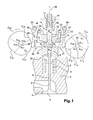
- FIG. 1 represents a first embodiment of a control device according to the invention, mounted on the cylinder head 1 of an internal combustion engine.
- the cylinder head 1 is conventionally equipped with at least one valve 2, for example an intake valve, comprising a head 3 held in abutment on a sealing seat 4 of the cylinder head 1, by a return spring 5.
- the valve 2 further comprises a rod 6 opposite to the head 3, supporting a cup 7 of support of one end of the return spring 5.
- the other end of the return spring is for example directly on the yoke 1.
- the device according to the invention comprises a body 8 fixed on the yoke 1, for example by screwing, and surrounding a cavity 9 communicating with the outside through four orthogonal cylinders 10, 11, 12, 13.
- a piston Ps is fixed to the free end of the rod 6 of the valve 2 and is slidably mounted in the first cylinder 10 of the body 8.
- the piston Ps is movable between a top dead center ( figure 1 ) for which the valve 2 is closed, that is to say rests on its seat 4, and a bottom dead point, for which the valve 2 is open at its maximum adjustable lift, that is to say is peeled of the seat 4.
- the pistons P1, P2 and Pa respectively called the opening piston, the closing piston and the shuttle piston, are slidably mounted respectively in the cylinders 11, 12 and 13 of the cavity 9.
- the pistons P1, P2, Pa and Ps delimit a portion of the cavity 9, filled with a substantially constant volume of incompressible fluid, such as oil, and whose sealing is ensured by the pistons P1, P2, Pa and Ps.
- the volume of fluid in the cavity 9 is the reference volume defined above, which does not evolve in operation, with the exception of possible leaks that can be compensated, as will be better described later.
- the pistons P1 and P2 are coaxial, as are the pistons Pa and Ps.
- the pistons P1 and P2 are furthermore oriented perpendicular to the pistons Pa and Ps.
- the piston Pa has an outer end 14, that is to say opposite to the cavity 9, comprising a flange 15 adapted to abut against an outer face 16 of the body 8 (internal abutment).
- the outer end 14 of the piston Pa is also able to bear against an external fixed stop 17 (external stop).
- the piston Pa is thus movable between its internal and external stops, a return spring 18 tending to push the shuttle piston Pa towards its internal stop.
- the shuttle piston Pa is movable between a top dead center, defined by the internal stop, and a bottom dead point, defined by the outer stop.
- the piston P1 is actuated by an opening cam C1, driven in rotation about an axis 19, by a first shaft (not shown).
- the piston P2 is actuated by a closure cam C2, driven in rotation about an axis 20, by a second shaft (not shown), synchronous and parallel to the first shaft and perpendicular to the section plane of the figure 1 .
- the axes 19, 20 intersect the common axis of the pistons P1 and P2.
- the direction of rotation of the cams C1, C2 is represented by arrows at the figure 1 and corresponds to the counterclockwise direction in this figure.
- the device according to the invention further comprises phase shift means (not shown) of the second shaft relative to the first shaft, or vice versa.
- the second shaft (and thus the closure cam C2) can be advanced in operation relative to the first shaft (and therefore with respect to the opening cam C1) up to a maximum phase shift angle.
- the outer ends of the pistons P1 and P2 comprise flanges 21, 22 cooperating with torsion springs 23, 24 mounted around fixed pins 25, 26 and tending to move the pistons P1 and P2 towards the outside of the cavity, c ' that is, towards their bottom dead center, so that the outer ends of the pistons P1 and P2 respectively bear on the opening cam C1 and closure C2, by means of rockers 27, 28 pivoting about fixed axes 29, 30 to avoid radial forces on the pistons P1 and P2.
- the opening C1 and closure C2 cams each comprise a base circle arc C11, C21 centered on the axis of rotation 19, 20 of each cam C1, C2 and a single lobe whose profile is constituted by a rising ramp C12, C22 making it possible to move the corresponding piston P1, P2 from its bottom dead center to its top dead center, followed by a second circular arc C13, C23 concentric with the base circle C11, C21 and of larger diameter than this one, to immobilize the opening pistons P1 and closing P2 at their top dead center, followed by a downward ramp C14, C24 to bring the opening pistons P1 and closing P2 to their neutral position low.
- the angular aperture ⁇ 11 of the basic circular arc C11 of the opening cam C1 is at least equal to the angular aperture ⁇ 22 of the rising ramp C22 of the closing cam C2, increased by the phase angle maximum between the first and second trees.
- the angular aperture ⁇ 21 of the basic circular arc C21 of the closing cam C2 is at least equal to the angular aperture ⁇ 14 of the descending ramp C14 of the aperture cam C1 increased by the angle maximum phase shift.
- the profile of each of the cams C1, C2 is continuous.
- the rising ramp C12 of the opening cam C1 and the downward ramp C24 of the closing cam C2 are so-called fast ramps.
- the rising ramp C22 of the closing cam C2 and the descending ramp C14 of the opening cam C1 are so-called slow ramps.
- the angular aperture ⁇ 12, ⁇ 24 of the fast ramps C12, C24 is smaller than the angular aperture ⁇ 14, ⁇ 22 of the slow ramps C14, C22
- the opening C1 and closure C2 cams are reversed in that the fast ramp C24 of the closing cam C2 is descending when the fast ramp C12 of the opening cam C1 is rising, and that the slow ramp C22 of the closure cam C2 is rising when the slow ramp C14 of the opening cam C1 is descending.
- the angular aperture ⁇ 13, ⁇ 23 of the second circular arcs C13, C23 is equal to that ⁇ 12, ⁇ 24 of the fast ramps C12, C24, in order to be able to reach the maximum lifting of the valve 2 of which the device is capable.
- the pistons P1 and P2 are identical and each move the same volume as the piston Pa between their bottom dead point and their top dead center. This volume is called common cylinder capacity.
- the stroke and the diameter of the piston Pa may be different from those of the pistons P1 and P2 to optimize the return spring 18 which generates in the cavity 9 a much lower pressure than that generated by the spring 5 of the valve 2, taking into account the the low inertia of the piston Pa and the slowness of the ramps C14 and C22.
- the return springs 18, 5 of the shuttle piston Pa and the valve 2 are such that the pressure of the fluid necessary for the displacement of the shuttle piston Pa to its bottom dead point is less than the pressure required to open the valve 2.
- the device according to the invention also comprises means of recalibration of the fluid reference volume in the cavity 9, comprising a supply conduit 32 in incompressible fluid equipped with a nonreturn valve 33 and connecting a source 34 of fluid under pressure at the cavity 9 (see Figures 4A and 5A ).
- the fluid pressure from the supply duct 32 is insufficient to move the piston Pa.
- recalibration means are known from the document WO 02/48510 , in the name of the Applicant.
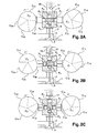
- FIGS 2A to 2E represent the different stages of the operation of the control device of the figure 1 during the duration of a cycle performed by a complete rotation of the cams C1 and C2.
- the cycle is represented for an intermediate phase shift cams C1 and C2, corresponding to an intermediate maximum lift of the valve 2 (see for example the curve 5 at the figure 3 ).
- the Figure 2A represents the device at the end of the recalibration phase of the fluid reference volume in the cavity 9, via the aforementioned recalibration means.
- the pistons P1 and P2 are at the bottom dead center on the base circle C11, C21 of the cams C1 and C2, the pistons Ps and Pa being at high dead point under the action of the return springs 5 and 18.
- the rotation of the cams C1, C2 thus produces no movement of the pistons and the hydraulic fluid in the cavity 9.
- the Figure 2B represents the device during the second phase of the cycle, called the arming phase, where the piston P1 remains stationary at its bottom dead point on the base circle C11 of the cam C1 when the piston P2, on the slow rising ramp C22 of the C2 cam drives into the cavity 9 a first common cylinder of fluid that pushes the shuttle piston Pa, the latter passing from its top dead center to its bottom dead stop by raising the pressure in the cavity 9 to compress the return spring 18 Pa piston.
- the Figure 2C represents the device at the end of the third phase of the cycle, said opening of the valve 2, where the valve 2 reaches its maximum lift, when the piston P1, on the fast ramp C12 of the cam C1, pushes in the cavity 9 a second common cylinder of fluid and that the piston P2 on the rapid descending ramp C24 of the cam C2 sucks a fraction of the volume discharged by P1 to limit the volume of fluid that pushes the piston Ps and to reduce the maximum lift of the valve 2 reached when the remaining volume to be discharged by the piston P1 is equal to the volume already sucked by the piston P2.
- the 2D figure represents the device at the end of the fourth phase of the so-called closing cycle of the valve 2, where the piston P1 is immobilized at its top dead center on the second circular arc C13 of the cam C1 when the piston P2, on the C24 fast descending ramp of the C2 cam sucks the fluid discharged by the piston Ps under the action of the return spring 5 which closes the valve 2.
- the figure 2E represents the device during the fifth phase of the disarming cycle, where the valve 2 has fallen back on its seat 4 and the piston Ps has found its top dead center, where the piston P2 has found its low dead point and where the piston P1 on the slow descending ramp C14 of the cam C1 sucks the common cylinder discharged by the piston Pa under the action of its return spring 18 to disarm the device and return to the position of the Figure 2A from which a new cycle can be approached.
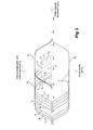
- FIG 3 shows an operating diagram of the device of the figure 1 whose abscissae represent the angle of rotation of the cams C1, C2 between the beginning and the end of a cycle, whose positive ordinates represent the volume of fluid discharged by the piston P1 (bold line), the volume of fluid discharged by the piston P2 (thin line) and the volume of fluid absorbed by the piston Ps of the valve 2 (dotted), and whose negative ordinate represents the volume of fluid absorbed by the shuttle piston Pa.
- the curves numbered 1 to 7 correspond to seven successive phase shifts between the shafts, the first curve 1 corresponding to a zero angle where the valve 2 is wide open and the last curve 7 corresponds to a phase shift of 50 degrees, for which the valve 2 no longer opens.
- the dotted curves thus also illustrate the lifting laws of the valve 2 for the seven phase shifts. It is recalled that the lifting of a valve 2 is the distance between the range of its head 3 and the seat 4 of the cylinder head 1.
- control device allows, in operation and by adjusting the phase shift between the two shafts, to adjust the maximum lift of the valve 2 and, simultaneously, to shift the closing angle of the valve 2 so as to adjust the duration angular opening of the valve 2 and, if necessary, to keep the valve 2 closed for the duration of a cycle.
- the relative angular setting of the shafts is defined in such a way that, for a zero phase shift angle (curve 1), the closure piston P2 leaves its top dead center at the same time that the opening piston P1 reaches its own, so that the maximum lifting of the valve 2 which is capable of the device is reached for a single angle of the cycle.
- the device may comprise means for erasing the abutment 17 of the bottom dead center of the shuttle piston Pa (shown schematically in FIG. figure 1 by an arrow 56), so that the piston Pa can suck the algebraic sum of the volumes of fluid discharged by the opening piston P1 and the closing piston P2, in order to prevent the arming of the device whatsoever the phase shift angle between the opening shaft and the closing shaft.
- FIGS. 4A and 4B illustrate a control device according to a second embodiment of the invention, for the synchronous actuation of two identical or twin valves 2a, 2b, via three cams C1a, C1b and C2, so as to ensure a hydraulic symmetry of the device.
- twin valves 2a, 2b have parallel axes and are actuated by two coaxial shafts 35, 36, whose axis is in the plane of the axes of the valves 2a, 2b and perpendicular to said axes, respectively carrying two cams of openings C1a, C1b a closure cam C2.
- the cams of openings C1a, C1b are arranged symmetrically on either side of the closure cam C2.
- the identical profiles of the cams C1 a, C1b and that of the cam C2 are similar to those described above.
- the body 8 has a cavity 9 and a plane of symmetry BB '.
- the cavity 9 opens outwards by six cylinders, respectively two parallel symmetrical cylinders 10a, 10b parallel to which slide two pistons Psa, Psb fixed on the free ends of the stems of the valves 2a, 2b, two other symmetrical cylinders 11a, 11b parallel to each other , where two opening pistons P1a, P1b slide, a first central cylinder 12 in which slides a closing piston P2, and a second perpendicular central cylinder 13 in which a shuttle piston Pa slides.
- the pistons Psa, Psb of the valves 2a, 2b, the opening pistons P1a, P1b and the closing piston P2 are parallel to each other.
- the shuttle piston Pa is orthogonal to the aforementioned pistons Psa, Psb, P1a, P1b, P2.
- the axis of the closing piston P2 and the axis of the shuttle piston Pa are located in the plane of symmetry BB 'of the body 8.
- the shuttle piston Pa is movable between inner and outer stops 16 and 17 respectively defining its top and bottom dead spots, a return spring 18 tending to push it towards its internal abutment 16.
- the return springs 18, 5a, 5b of the shuttle piston Pa and the valves 2a, 2b are such that the pressure of the fluid necessary for the displacement of the shuttle piston Pa to its bottom dead point is less than the pressure required to open the any of the valves 2a, 2b.
- the two opening cams C1a, C1b are identical, as are the two opening pistons P1a, P1b, that the two valve pistons Psa, Psb, that the two valves 2a, 2b and that the springs of recall 5a, 5b.
- the control device is thus symmetrical with respect to the plane BB '.
- each valve 2a, 2b comprises a head 3a, 3b intended to rest on a seat 4a, 4b of a yoke 4 on which is fixed the body 8, for example by screwing.
- Each cam C1a, C1b, C2 actuates the corresponding piston P1a, P1b, P2 via a pawl 27a, 27b, 28, pivoting about an axis 29a, 29b 30.
- the opening pistons P1 a, P1 b and P2 closing are maintained in contact with the latches 27a, 27b, 28, and the latches 27a, 27b, 28 are maintained in contact with the cams C1a, C1b, C2, through the springs of recall 23a, 23b, 24 tending to move the pistons P1a, P1b, P2 to their bottom dead center.
- the closing cam C2 is integral with the internal shaft 36, the latter being coupled to the coaxial outer shaft 35 carrying the opening cams C1a, C1b, via a not shown phase shifter.
- phase shifter is well known from the state of the art and will not be detailed here.
- the closing cam C2 is secured to the internal shaft 36 by a pin 37 which passes through the outer shaft 35 by two oblong slots 38 allowing the desired phase variation.
- the volume displaced by the closing piston P2 and the shuttle piston Pa is equal to twice the volume displaced by each opening piston P1a, P1b.
- the cavity 9 also communicates with a fluid source 34 under pressure via a duct 32 equipped with a unidirectional valve 33 oriented in the plane of symmetry BB '.
- the opening and closing flows of the twin valves 2a, 2b run on identical hydraulic paths, which guarantees the synchronism of the valves 2a, 2b provided that their return springs 5a , 5b are perfectly identical.
- the control device is housed inside a camshaft support 50 fixed on the yoke 1, for example by screwing.
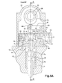
- FIGS. Figures 5A and 5B A control device according to a third embodiment is shown in FIGS. Figures 5A and 5B .
- This aims to mechanically ensure the synchronism of two twin valves 2a, 2b whose return springs 5a, 5b are not perfectly identical, from an asymmetrical hydraulic circuit activated by two cams only.
- twin valves 2a, 2b have parallel axes and are actuated, via a spreader 39, by two coaxial shafts, respectively external 35 and internal 36, respectively carrying an opening cam C1 and a closing cam C2.
- the profiles of the cams C1, C2 are similar or identical to those described above.
- the body 8 has a cavity 9 and a plane of symmetry BB '.
- the cavity 9 opens outwards by four cylinders, respectively a cylinder 10 which slides a piston Ps formed by a part of the spreader bar 39 ( Figure 5B ), a cylinder 11 in which slides an opening piston P1, a cylinder 12 in which a closing piston P2 slides, and a cylinder 13 in which a shuttle piston Pa slides.
- the opening piston P1, the closing piston P2 are parallel. between them.
- the shuttle piston Pa is, for example, orthogonal to the aforementioned pistons P1, P2, Ps.
- the shuttle piston Pa and the piston Ps of the spreader bar 39 have their axes in the plane of symmetry BB 'of the body 8.
- the opening pistons P1 and P2 closing pistons are identical and are arranged on either side of the plane of symmetry BB 'of the body 8.
- the shuttle piston Pa is movable between two stops, respectively defining its top and bottom dead spots, a return spring 18 tending to push it towards its top dead center.
- the shuttle piston Pa is formed of two parts 40, 41 assembled to each other, for example by screwing, a first part 40 comprising a flange 42 intended to abut against an internal sealing seat 43 of the cylinder 13, so as to define the bottom dead stop and limit leakage, a second portion 41 having a flange 44 intended to abut against an outer wall 45 of the body 8, so as to define the stop point dead high.
- the return springs 18, 5a, 5b of the shuttle piston Pa and the valves 2a, 2b are such that the pressure of the fluid necessary for the displacement of the shuttle piston Pa to its bottom dead point is less than the pressure required to open the valves 2a, 2b.
- each valve 2a, 2b comprises a head 3a, 3b intended to rest on a seat 4a 4b of a yoke 1 on which is fixed the body 8, for example by screwing.
- the free ends of the rods of the valves 2a, 2b each bear on a flange 46a, 46b of the spreader 39.
- the spreader 39 has a central portion intended to form the piston Ps mounted in the cylinder 10 of the body 8, and two symmetrical wings 46a, 46b extending laterally on either side of the central portion. The movement of the spreader 39 thus causes the synchronous movement of the twin valves 2a, 2b, even if the return springs 5a, 5b of said valves 2a, 2b are not perfectly identical.
- Each cam C1, C2 actuates the corresponding piston P1, P2 through an articulated roller rocker arm.
- Each rocker arm has an arm 47 pivoting about a fixed axis 49 and carrying the axis 51 of a roller 48 in contact with the cam.
- Each rocker arm further comprises a clevis articulated on the axis 51 of the roller 48, comprising two lateral branches 52 extending on either side of the roller 48 and traversed by the shaft 51, and a central branch 53, solidarizing the lateral branches 52, and carrying a rod the end comprises a sphere 54 trapped in a complementary spherical housing 55 formed in the corresponding piston P1, P2, so as to form a ball joint connection between the yoke and the corresponding piston P1, P2.
- rollers 48 are held in contact with the cams C1, C2, by means of return springs, not shown.
- the inner shaft 36 is coupled to the coaxial outer shaft via a not shown phase shifter.
- the closure cam C2 is secured to the internal shaft 36 by a pin 37 which passes through the outer tube 35 by two oblong slots allowing the desired phase variation.
- the volumes displaced by the opening piston P1, the closing piston P2 and the shuttle piston Pa are equal to each other.
- the cavity 9 also communicates with a source of fluid 34 under pressure, via a duct 32 equipped with a unidirectional valve 33.
- control device is housed inside a camshaft support 50 fixed on the yoke 1, for example by screwing.
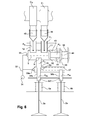
- figure 6 represents two parallel twin valves 2a, 2b whose lifts are equal.
- a control device is identical to the previous one to the cylinder 10 where the piston Ps slides.
- the body 8 comprises an additional non-deformable hydraulic cavity 57 communicating with the cavity 9 via the cylinder 10 and communicating with the outside via a cylinder 58a, of axis parallel to the cylinder 10, and preferably coaxial with the cylinder 10, and via a cylinder 58b which is not necessarily parallel to the cylinder 58a.
- a piston Ps slides in the cylinder 10 and is integral with a piston Psa, of smaller diameter (half section in the figure), which slides in the cylinder 58a and is integral and parallel to the valve stem 2a.
- the cavity 57 closed by the pistons Ps, Psa, Psb contains a constant volume of hydraulic fluid equal to its volume when the valves 2a and 2b rest on their seats in the closed position.
- the cavity 57 communicates with the pressure source 34 via a nonreturn valve 33a.
- the piston Ps activates the valve 2a via the piston Psa, the assembly being mechanically secured and therefore having the same stroke.
- the operating clearance of the valve 2a is canceled by the valve 33.
- the piston Ps delivers a volume of oil proportional to the difference in section between the pistons Ps in the cavity 57. and Psa which is absorbed by the displacement of the piston Psb which actuates the valve 2b.
- the operating clearance of the valve 2b is canceled by the valve 33a.
- This embodiment allows the piston Ps to move the valves 2a and 2b in synchronism with different lifts and non-parallel axes of movement.
- the lifting of the valve 2b is equal to that of the valve 2a multiplied by the ratio between the section difference Ps-Psa and the section Psb.
Landscapes
- Engineering & Computer Science (AREA)
- Mechanical Engineering (AREA)
- General Engineering & Computer Science (AREA)
- Valve Device For Special Equipments (AREA)
Claims (15)
- Vorrichtung zur Steuerung zumindest eines Ventils (2), beispielsweise bei einem Hubkolbenmotor, das in eine geradlinige Hin- und Herschiebebewegung versetzt wird, die dazu bestimmt ist, eine Öffnung mit Dichtsitz (4) zu öffnen bzw. zu schließen, wobei das Ventil (2) ein Federrückstellmittel (5) zum Rückstellen in eine Schließstellung aufweist, wobei die Vorrichtung einen Körper (8) mit einem unverformbaren Hohlraum (9) aufweist, der über zumindest vier geradlinige Zylinder (10, 11, 12, 13) ausschließlich mit dem Außenbereich kommuniziert, die mit vier jeweiligen Kolben (P1, P2, Pa, Ps) verschlossen sind, die mit einer Hin- und Herbewegung zwischen einem unteren Totpunkt, der vom Inneren des Hohlraums (9) entfernt liegt, und einem oberem Totpunkt verstellbar sind, der dem Inneren des Hohlraums (9) angenähert ist, dadurch gekennzeichnet, dass die Kolben ein Kolben (Ps), der mechanisch mit dem Ventil (2) verbunden und seinem Rückstellmittel (5) entgegen gerichtet ist, ein Öffnungskolben (P1), der über eine Öffnungssteuerkurve (C1) betätigt wird, die über eine erste Welle drehend angetrieben wird, ein Schließkolben (P2), der über eine Schließsteuerkurve (C2) betätigt wird, die über eine zweite Welle drehend angetrieben wird, die sich synchron zur ersten Welle dreht und gegenüber der ersten Welle um einen im Betrieb einstellbaren Winkel versetzt angeordnet sein kann, und ein Pendelkolben (Pa) sind, der sich zwischen einem ersten festen Anschlag (17), der den unteren Totpunkt definiert, und einem zweiten festen Anschlag (16) verlagert, der den oberen Totpunkt definiert, zu dem hin der Pendelkolben (Pa) über ein Federmittel (18) zurückgestellt wird, dass der Abschnitt des Hohlraums (9), der von den Kolben (P1, P2, Pa, Ps) eingegrenzt wird, mit einem bestimmten, konstanten Referenzvolumen an im Wesentlichen inkompressiblen Hydraulikmedium dann gefüllt wird, wenn das Ventil (2) auf seinen Sitz (4) aufliegt, wenn der Öffnungs- (P1) und der Schließkolben (P2) an ihrem unteren Totpunkt sind und wenn der Pendelkolben (Pa) an seinem oberen Totpunkt ist, dass der Öffnungskolben (P1), der Schließkolben (P2) und der Pendelkolben (Pa) einen gemeinsamen Hubraum haben und das gleiche Volumen an Medium zwischen ihrem unteren Totpunkt und ihrem oberen Totpunkt verlagern, und dass die Federrückstellmittel (18, 5) des Pendelkolbens (Pa) und des Ventils (2) derart sind, dass der Druck des Mediums, der für die Verlagerung des Pendelkolbens (Pa) bis zu seinem unteren Totpunkt erforderlich ist, geringer ist als der zum Öffnen des Ventils (2) erforderliche Druck.
- Steuervorrichtung nach Anspruch 1, dadurch gekennzeichnet, dass die zweite Welle im Betrieb gegenüber der ersten Welle bis zu einem maximalen Phasenverschiebungswinkel vorgerückt werden kann, wobei die Öffnungssteuerkurve (C1) und die Schließsteuerkurve (C2) jeweils einen Basiskreisbogen (C11, C21) und einen einzigen Lappen aufweisen, dessen Profil aus einer ansteigenden Rampe (C12, C22) besteht, über welche der entsprechende Kolben (P1, P2) von seinem unteren Totpunkt zu seinem oberen Totpunkt verlagert werden kann und der ein zweiter Kreisbogen (C13, C23) folgt, der konzentrisch zum Basiskreis (C11, C21) verläuft und im Durchmesser größer als dieser ist, wodurch es möglich ist, den Öffnungskolben (P1) und den Schließkolben (P2) an ihrem oberen Totpunkt festzulegen, dem eine absteigende Rampe (C14, C24) folgt, über welche der Öffnungskolben (P1) und der Schließkolben (P2) zu ihrem unteren Totpunkt zurückgeführt werden können, wobei der Öffnungswinkel (α11) des Basiskreisbogens (C11) der Öffnungssteuerkurve (C1) zumindest gleich dem Öffnungswinkel (α22) der ansteigenden Rampe (C22) der Schließsteuerkurve (C2) ist, erhöht um den maximalen Phasenverschiebungswinkel, wobei der Öffnungswinkel (α21) des Basiskreisbogens (C21) der Schließsteuerkurve (C2) zumindest gleich dem Öffnungswinkel (α14) der absteigenden Rampe (C14) der Öffnungssteuerkurve (C1) ist, erhöht um den maximalen Phasenverschiebungswinkel.
- Steuervorrichtung nach Anspruch 2, dadurch gekennzeichnet, dass über den gesamten Phasenverschiebungsbereich die relative Winkellage der ersten und der zweiten Welle derart ist, dass der Öffnungskolben (P1) unter der Wirkung der ansteigenden Rampe (C12) der Öffnungssteuerkurve (C1) seinen unteren Totpunkt verlässt, nachdem der Pendelkolben (Pa) unter der Wirkung der ansteigenden Rampe (C22) der Schließsteuerkurve (C2) seinen oberen Totpunkt erreicht hat, und dass der Schließkolben (P2) unter der Wirkung der absteigenden Rampe (C24) der Schließsteuerkurve (C2) seinen unteren Totpunkt erreicht, bevor der Öffnungskolben (P1) unter der Wirkung der absteigenden Rampe (C14) der Öffnungssteuerkurve (C1) seinen oberen Totpunkt verlässt.
- Steuervorrichtung nach Anspruch 3, dadurch gekennzeichnet, dass die relative Winkellage der Wellen derart definiert ist, dass bei einem Phasenverschiebungswinkel von null zwischen der ersten und der zweiten Welle, welcher der maximalen Öffnungsdauer des Ventils entspricht, der Schließkolben (P2) seinen oberen Totpunkt verlässt, nachdem der Öffnungskolben (P1) den seinigen erreicht hat, so dass ein anfänglicher Phasenverschiebungsbereich geschaffen wird, bei dem das Ventil (2) zwischen seiner Öffnungs- und seiner Schließphase für eine gewisse Zeit in seinem maximalen Hub verbleibt.
- Steuervorrichtung nach Anspruch 3, dadurch gekennzeichnet, dass die relative Winkellage der Wellen derart definiert ist, dass bei einem Phasenverschiebungswinkel von null zwischen der ersten und der zweiten Welle, der Schließkolben (P2) seinen oberen Totpunkt verlässt, bevor der Öffnungskolben (P1) den seinigen erreicht.
- Steuervorrichtung nach einem der Ansprüche 2 bis 5, dadurch gekennzeichnet, dass der maximale Phasenverschiebungswinkel der Schließsteuerkurve (C2) gegenüber der Öffnungssteuerkurve (C1) ausreicht, damit der Schließkolben (P2) seinen oberen Totpunkt verlässt, bevor der Öffnungskolben (P1) seinen unteren Totpunkt verlässt und damit zu jedem Zeitpunkt der Öffnungsphase des Ventils das Volumen an Medium, das vom Schließkolben (P2) ausgehend von seinem oberen Totpunkt angesaugt wird, größer ist als das Volumen an Medium, das vom Öffnungskolben (P1) ausgehend von seinem unten Totpunkt verdrängt wird, so dass bei einer verdrängten Gesamtdurchsatzmenge, die geringer oder gleich dem gemeinsamen Hubraum ist, das Ventil (2) während der gesamten Zyklusdauer geschlossen bleibt und der Pendelkolben (Pa) seinen unteren Totpunkt verlässt und wiedererreicht, um das Volumen des Hohlraums auf seinem Referenzwert zu halten.
- Steuervorrichtung nach einem der Ansprüche 1 bis 6, dadurch gekennzeichnet, dass die Winkelöffnungsdauer des Ventils (2) sowie sein Hub im Betrieb eingestellt werden, indem der Phasenverschiebungswinkel der zweiten Welle verändert wird und die erste Welle fest gehalten wird, oder umgekehrt, oder auch indem zugleich der Phasenverschiebungswinkel einer jeden Welle bezüglich einer die Wellen antreibenden Kurbelwelle verändert wird.
- Steuervorrichtung nach einem der Ansprüche 1 bis 7, dadurch gekennzeichnet, dass die Profile der Öffnungs- (C1) und der Schließsteuerkurve (C2) derart sind, dass eine Ruhezeit besteht, während der das Ventil (2) in Schließstellung ist, der Pendelkolben (Pa) an seinem oberen Totpunkt ist und der Öffnungs- (P1) und der Schließkolben (P2) an ihren unteren Totpunkten sind, wodurch es möglich ist, Lecks aus dem Hohlraum (9) auszugleichen, um bei einem zum Verlagern des Pendelkolbens (Pa) ungenügenden Druck das Referenzvolumen des Mediums über eine unidirektionale Kommunikation (32, 33) mit einer Mediumsquelle (34) neu zu kalibrieren.
- Steuervorrichtung nach einem der Ansprüche 1 bis 8, dadurch gekennzeichnet, dass sie eine Anzahl N von identischen Ventilen (2) synchron steuert und eine Anzahl P von Öffnungskolben (P1) aufweist, die zueinander synchron sind und über Q identische Öffnungssteuerkurven (C1) betätigt werden, sowie eine Anzahl R von Schließkolben (P2), die zueinander synchron sind und über S identische Schließsteuerkurven (C2) betätigt werden, und zumindest einen Pendelkolben (Pa), wobei das über die P Öffnungskolben (P1) zwischen ihrem unteren Totpunkt und ihrem oberen Totpunkt verlagerte Gesamtvolumen identisch zum Gesamtvolumen ist, das über die R Schließkolben (P2) zwischen ihrem unteren Totpunkt und ihrem oberen Totpunkt verlagert wird und auch identisch zu dem Gesamtvolumen ist, das über den bzw. die Pendelkolben (Pa) zwischen seinem/ihrem unteren Totpunkt und seinem/ihrem oberen Totpunkt verlagert wird.
- Anordnung von zwei Vorrichtungen nach einem der Ansprüche 1 bis 8, von denen jede dazu bestimmt ist, ein einziges Ventil (2) zu betätigen, dadurch gekennzeichnet, dass sie sich eine einzige Öffnungssteuerkurve (C1) und eine einzige Schließsteuerkurve (C2) teilen, die sie gemein haben, so dass der Gleichlauf beim Öffnen und beim Schließen der Ventile (2) sichergestellt ist.
- Vorrichtung nach einem der Ansprüche 1 bis 8, dadurch gekennzeichnet, dass sie zumindest zwei identische Ventile (2a, 2b) über einen Steuerhebel (39) oder einen Synchronisationskipphebel betätigt.
- Steuervorrichtung nach einem der Ansprüche 1 bis 8, dadurch gekennzeichnet, dass der Körper (8) einen zusätzlichen unverformbaren Hohlraum (57) aufweist, der über einen ersten Zylinder (10) mit dem Hohlraum (9) kommuniziert und über einen geradlinigen zweiten Zylinder (58a) mit dem Außenbereich kommuniziert, der einen geringeren Querschnitt als der erste Zylinder (10) aufweist und parallel und entgegengesetzt zum ersten Zylinder (10) verläuft, sowie über einen dritten geradlinigen Zylinder (58b), wobei der zusätzliche Hohlraum (57) unidirektional mit einer Druckmediumsquelle (34) kommuniziert, und dass ein erster Kolben (Ps) in dem ersten Zylinder (10) gleitet und ein zweiter Kolben (Psa) in dem zweiten Zylinder (58a) gleitet, wobei der zweite Kolben (Psa) mit dem ersten Kolben (Ps) und mit einem ersten Ventil (2a) verbunden ist, dessen Achse parallel zum ersten und zum zweiten Kolben (Ps, Psa) verläuft, dass ein dritter Kolben (Psb) in dem dritten Zylinder (58b) gleitet, wobei der dritte Kolben (Psb) mit einem zweiten Ventil (2b) verbunden ist, dessen Achse parallel zum dritten Kolben (Psb) ist, und dass der zusätzliche Hohlraum (57) ein im Wesentlichen inkompressibles Mediumvolumen enthält, das dann gleich dem Volumen des zusätzlichen Hohlraums (57) ist, wenn das erste und das zweite Ventil (2a, 2b) auf ihren Sitzen in Schließstellung der Ventile (2a, 2b) aufliegen.
- Steuervorrichtung nach einem der Ansprüche 1 bis 12, dadurch gekennzeichnet, dass die erste und die zweite Welle (35, 36) koaxial verlaufen.
- Steuervorrichtung nach einem der Ansprüche 1 bis 12, dadurch gekennzeichnet, dass sie eine Einrichtung zum Aufheben des ersten Anschlags (17) am unteren Totpunkt des Pendelkolbens (Pa) aufweist, so dass der Kolben (Pa) die algebraische Summe der Mediumvolumen ansaugen kann, die von dem Öffnungskolben (P1) und dem Schließkolben (P2) verdrängt werden, um das Öffnen des Ventils (2) unabhängig vom Phasenverschiebungswinkel zwischen der Öffnungswelle und der Schließwelle zu verhindern.
- Verfahren zum Betreiben einer Steuervorrichtung nach einem der Ansprüche 2 bis 14, dadurch gekennzeichnet, dass bei jeder Umdrehung der Wellen ein Öffnungs- und Schließzyklus des Ventils (2) erfolgt, der die aufeinanderfolgenden Schritte umfasst, die darin bestehen, ausgehend von einer Ruhestellung der Steuervorrichtung, in welcher das Ventil (2) auf seinem Sitz (4) aufliegt, in welcher der Öffnungs- (P1) und der Schließkolben (P2) an ihrem unteren Totpunkt sind und in welcher der Pendelkolben (Pa) an seinem oberen Totpunkt ist:- Verlagern des Schließkolbens (P2) von seinem unteren Totopunkt zu seinem oberen Totpunkt über die ansteigende Rampe (C22) der Schließsteuerkurve (C2), so dass der Pendelkolben (Pa) von seinem oberen Totpunkt zu seinem unteren Totpunkt verschoben wird, um die Steuervorrichtung zu spannen, wobei der Öffnungskolben (P1) an seinem unteren Totpunkt verbleibt, und zwar über den Basiskreisbogen (C11) der Öffnungssteuerkurve (C1),- Verlagern des Öffnungskolbens (P1) über die ansteigende Rampe (C12) der Öffnungssteuerkurve (C1), so dass das Ventil (2) zu öffnen beginnt, wobei der Schließkolben (P2) an seinem oberen Totpunkt verbleibt, und zwar über den zweiten Kreisbogen (C23) der Schließsteuerkurve (C2),- Einstellen des Hubs und der Öffnungsdauer des Ventils (2), indem die Schließsteuerkurve (C2) gegenüber der Öffnungssteuerkurve (C1) phasenverschoben wird, um den Schließkolben (P2) ausgehend von seinem oberen Totpunkt über die absteigende Rampe (C24) der Schließsteuerkurve (C2) zu einem beliebigen Zeitpunkt des Druckhubs des Öffnungskolbens (P1) über die ansteigende Rampe (C12) der Öffnungssteuerkurve (C1) zu verlagern, bevor er wieder seinen oberen Totpunkt erreicht,- Fortsetzen der Verlagerung des Schließkolbens (P2) bis zu seinem unteren Totpunkt über die absteigende Rampe (C24) der Schließsteuerkurve (C2), so dass das Ventil (2) geschlossen wird, wobei der Öffnungskolben (P1) an seinem oberen Totpunkt verbleibt, und zwar über den zweiten Kreisbogen (C13) der Öffnungssteuerkurve (C1),- Verlagern des Öffnungskolbens (P1) zu seinem unteren Totpunkt über die absteigende Rampe (C14) der Öffnungssteuerkurve (C1), so dass der Pendelkolben (Pa) von seinem unteren Totpunkt zu seinem oberen Totpunkt verlagert wird und die Steuervorrichtung entspannt wird.
Applications Claiming Priority (3)
| Application Number | Priority Date | Filing Date | Title |
|---|---|---|---|
| US201261594069P | 2012-02-02 | 2012-02-02 | |
| FR1250963A FR2986558B1 (fr) | 2012-02-02 | 2012-02-02 | Dispositif de commande variable d'au moins une soupape, par exemple pour un moteur alternatif |
| PCT/FR2013/050188 WO2013114041A1 (fr) | 2012-02-02 | 2013-01-30 | Dispositif de commande variable d'au moins une soupape, par exemple pour un moteur alternatif |
Publications (2)
| Publication Number | Publication Date |
|---|---|
| EP2809895A1 EP2809895A1 (de) | 2014-12-10 |
| EP2809895B1 true EP2809895B1 (de) | 2015-12-30 |
Family
ID=46062470
Family Applications (1)
| Application Number | Title | Priority Date | Filing Date |
|---|---|---|---|
| EP13706592.6A Active EP2809895B1 (de) | 2012-02-02 | 2013-01-30 | Vorrichtung zur variablen steuerung mindestens eines ventils, zum beispiel für eine hubkolbenmaschine |
Country Status (6)
| Country | Link |
|---|---|
| US (1) | US9181823B2 (de) |
| EP (1) | EP2809895B1 (de) |
| KR (1) | KR102000119B1 (de) |
| CN (1) | CN104136723B (de) |
| FR (1) | FR2986558B1 (de) |
| WO (1) | WO2013114041A1 (de) |
Families Citing this family (4)
| Publication number | Priority date | Publication date | Assignee | Title |
|---|---|---|---|---|
| US10184363B2 (en) | 2015-09-22 | 2019-01-22 | Jacobs Vehicle Systems, Inc. | Lost motion differential valve actuation |
| KR101796255B1 (ko) * | 2016-06-30 | 2017-11-10 | 주식회사 현대케피코 | 연속 가변 밸브 듀레이션 시스템 및 그 동작 방법 |
| GB2568044A (en) * | 2017-11-01 | 2019-05-08 | Eaton Srl | Valve train assembly |
| AU2019352632A1 (en) * | 2018-10-05 | 2021-04-29 | James Domenic Krajancich | Improved combustion engine |
Family Cites Families (15)
| Publication number | Priority date | Publication date | Assignee | Title |
|---|---|---|---|---|
| GB313231A (en) * | 1928-03-21 | 1929-06-13 | Thomas Henry Wintringham | Improvements in driving gear for use with internal combustion engines |
| DE4420064A1 (de) * | 1994-06-08 | 1995-12-14 | Bayerische Motoren Werke Ag | Ventiltrieb mit variabler Steuerung der Ventilöffnungswinkel |
| JPH09133031A (ja) * | 1995-11-13 | 1997-05-20 | Mitsubishi Motors Corp | 圧縮開放型エンジン補助ブレーキ装置 |
| IT1285853B1 (it) | 1996-04-24 | 1998-06-24 | Fiat Ricerche | Motore a combustione interna con valvole ad azionamento variabile. |
| DE19913742A1 (de) | 1999-03-26 | 2000-09-28 | Bayerische Motoren Werke Ag | Vorrichtung zur Hubverstellung eines Gaswechselventils im Zylinderkopf einer Brennkraftmaschine |
| NL1013811C2 (nl) * | 1999-12-09 | 2000-11-28 | Prometheus Engineering B V | Hydraulisch klepbedieningsmechanisme. |
| EP1341993B1 (de) * | 2000-12-15 | 2007-05-02 | Jean Frédéric Melchior | Variable ventilsteuerungseinrichtung ,brennkraftmaschine mit einem solchen einrichtung, und verfahren zum ventilsteuerung und turboladung |
| ITTO20020234A1 (it) | 2002-03-15 | 2003-09-15 | Fiat Ricerche | Motore pluricilindrico a combustione interna con dispositivo idraulico a controllo elettronico per l'azionamento variabile delle valvole e d |
| EP1375843B1 (de) * | 2002-06-28 | 2004-04-28 | AVL List GmbH | Brennkraftmaschine mit innerer Verbrennung |
| US7007650B2 (en) * | 2003-10-31 | 2006-03-07 | Caterpillar Inc | Engine valve actuation system |
| CN100446467C (zh) * | 2005-07-15 | 2008-12-24 | 华为技术有限公司 | 链路故障的恢复方法 |
| JP4459989B2 (ja) * | 2007-07-30 | 2010-04-28 | 三菱自動車工業株式会社 | 可変動弁機構付のエンジン |
| JP5131478B2 (ja) * | 2008-11-12 | 2013-01-30 | 三菱自動車工業株式会社 | 内燃機関の可変動弁装置 |
| EP2204566B1 (de) * | 2008-12-29 | 2011-06-29 | Fiat Group Automobiles S.p.A. | Adaptives Steuersystem des Luft-Kraftstoff-Verhältnisses einer Brennkraftmaschine mit einem variablen Ventilsteuerungssystem |
| KR101209726B1 (ko) * | 2010-06-25 | 2012-12-07 | 현대자동차주식회사 | 가변 밸브 리프트 장치 |
-
2012
- 2012-02-02 FR FR1250963A patent/FR2986558B1/fr not_active Expired - Fee Related
-
2013
- 2013-01-30 CN CN201380009333.4A patent/CN104136723B/zh active Active
- 2013-01-30 US US14/375,559 patent/US9181823B2/en active Active
- 2013-01-30 KR KR1020147022470A patent/KR102000119B1/ko active IP Right Grant
- 2013-01-30 EP EP13706592.6A patent/EP2809895B1/de active Active
- 2013-01-30 WO PCT/FR2013/050188 patent/WO2013114041A1/fr active Application Filing
Also Published As
| Publication number | Publication date |
|---|---|
| WO2013114041A1 (fr) | 2013-08-08 |
| FR2986558A1 (fr) | 2013-08-09 |
| US9181823B2 (en) | 2015-11-10 |
| US20150013630A1 (en) | 2015-01-15 |
| KR102000119B1 (ko) | 2019-07-15 |
| KR20140120334A (ko) | 2014-10-13 |
| FR2986558B1 (fr) | 2014-03-07 |
| CN104136723B (zh) | 2017-07-07 |
| EP2809895A1 (de) | 2014-12-10 |
| CN104136723A (zh) | 2014-11-05 |
Similar Documents
| Publication | Publication Date | Title |
|---|---|---|
| EP2307687B1 (de) | Kugelhubvorrichtung zur einstellung des verdichtungsverhältnisses für einen motor mit veränderlichem verdichtungsverhältnis | |
| EP0460988B1 (de) | Steuervorrichtung mit Nockenwelle und Kraftübertragungsmittel mit Rolle | |
| EP2809895B1 (de) | Vorrichtung zur variablen steuerung mindestens eines ventils, zum beispiel für eine hubkolbenmaschine | |
| EP2764217A2 (de) | Elektrohydraulisches ventilstellglied mit alternierendem nocken | |
| WO2003089764A1 (fr) | Detendeur a debit variable et distribution par soupape a commande progressive pour moteur a injection d'air comprime fonctionnant en mono et pluri energie et autres moteurs ou compresseurs | |
| FR2933141A1 (fr) | Dispositif de levee de bille a vis pour moteur a taux de compression variable. | |
| EP2279332B1 (de) | Verbrennungsmotor | |
| FR2830046A1 (fr) | Moteur a combustion interne comportant au moins deux soupapes d'echange de gaz commandees en synchronisme | |
| WO2002090728A1 (fr) | Dispositif de commande de la cinematique de soupapes | |
| EP0027949A1 (de) | Variable Ventilsteuerung für Brennkraftmaschinen mit Hubventilen und Nockenwelle | |
| EP0024994A1 (de) | Verfahren und Vorrichtung für die Verbesserung des Wirkungsgrades einer Brennkraftmaschine durch selektive Änderung des Kompressionsverhältnisses in Hinsicht auf Motorbelastung | |
| FR2891004A1 (fr) | Dispositif d'actionnement d'une soupape comprenant un arbre a cames decentrees portant une came mobile | |
| FR2857408A1 (fr) | Moteur a combustion interne a balayage des gaz brules residuels presents dans une chambre de combustion et procede permettant un tel balayage | |
| EP3692248B1 (de) | Hydraulik-ventil-stellglied mit regenerierungs-funktion | |
| FR2663981A1 (fr) | Dispositif de reglage de la commande des soupapes d'un moteur a combustion interne. | |
| FR2684135A1 (fr) | Dispositif de reglage de la commande des soupapes d'un moteur a combustion interne. | |
| WO2005024191A2 (fr) | Dispositif de commande hydraulique d'ouverture de soupapes de moteurs à combustion interne | |
| FR2899276A1 (fr) | Dispositif de commande de levee variable de soupapes | |
| FR3103216A1 (fr) | Système de commande pour une soupape d’admission sur piston d’un moteur deux temps | |
| WO1993025802A1 (fr) | Dispositif pour distribution rotative | |
| BE1000746A4 (fr) | Systeme de distribution d'un moteur a explosion. | |
| FR2865779A1 (fr) | Dispositif de commande hydraulique de soupapes de moteur a combustion interne | |
| BE385731A (de) | ||
| FR2686373A1 (fr) | Dispositif destine a faire varier le calage d'un arbre a cames et le temps d'ouverture des soupapes, d'un moteur a explosion a quatre temps. | |
| FR2859236A1 (fr) | Commande hydraulique de soupapes de moteur a combustion interne |
Legal Events
| Date | Code | Title | Description |
|---|---|---|---|
| PUAI | Public reference made under article 153(3) epc to a published international application that has entered the european phase |
Free format text: ORIGINAL CODE: 0009012 |
|
| 17P | Request for examination filed |
Effective date: 20140724 |
|
| AK | Designated contracting states |
Kind code of ref document: A1 Designated state(s): AL AT BE BG CH CY CZ DE DK EE ES FI FR GB GR HR HU IE IS IT LI LT LU LV MC MK MT NL NO PL PT RO RS SE SI SK SM TR |
|
| AX | Request for extension of the european patent |
Extension state: BA ME |
|
| DAX | Request for extension of the european patent (deleted) | ||
| GRAP | Despatch of communication of intention to grant a patent |
Free format text: ORIGINAL CODE: EPIDOSNIGR1 |
|
| INTG | Intention to grant announced |
Effective date: 20150624 |
|
| GRAS | Grant fee paid |
Free format text: ORIGINAL CODE: EPIDOSNIGR3 |
|
| GRAA | (expected) grant |
Free format text: ORIGINAL CODE: 0009210 |
|
| AK | Designated contracting states |
Kind code of ref document: B1 Designated state(s): AL AT BE BG CH CY CZ DE DK EE ES FI FR GB GR HR HU IE IS IT LI LT LU LV MC MK MT NL NO PL PT RO RS SE SI SK SM TR |
|
| REG | Reference to a national code |
Ref country code: GB Ref legal event code: FG4D Free format text: NOT ENGLISH |
|
| REG | Reference to a national code |
Ref country code: CH Ref legal event code: EP |
|
| REG | Reference to a national code |
Ref country code: AT Ref legal event code: REF Ref document number: 767596 Country of ref document: AT Kind code of ref document: T Effective date: 20160115 |
|
| REG | Reference to a national code |
Ref country code: IE Ref legal event code: FG4D Free format text: LANGUAGE OF EP DOCUMENT: FRENCH |
|
| REG | Reference to a national code |
Ref country code: DE Ref legal event code: R096 Ref document number: 602013004366 Country of ref document: DE |
|
| REG | Reference to a national code |
Ref country code: FR Ref legal event code: PLFP Year of fee payment: 4 |
|
| REG | Reference to a national code |
Ref country code: LT Ref legal event code: MG4D |
|
| PG25 | Lapsed in a contracting state [announced via postgrant information from national office to epo] |
Ref country code: HR Free format text: LAPSE BECAUSE OF FAILURE TO SUBMIT A TRANSLATION OF THE DESCRIPTION OR TO PAY THE FEE WITHIN THE PRESCRIBED TIME-LIMIT Effective date: 20151230 Ref country code: NO Free format text: LAPSE BECAUSE OF FAILURE TO SUBMIT A TRANSLATION OF THE DESCRIPTION OR TO PAY THE FEE WITHIN THE PRESCRIBED TIME-LIMIT Effective date: 20160330 Ref country code: LT Free format text: LAPSE BECAUSE OF FAILURE TO SUBMIT A TRANSLATION OF THE DESCRIPTION OR TO PAY THE FEE WITHIN THE PRESCRIBED TIME-LIMIT Effective date: 20151230 |
|
| REG | Reference to a national code |
Ref country code: NL Ref legal event code: MP Effective date: 20151230 |
|
| REG | Reference to a national code |
Ref country code: AT Ref legal event code: MK05 Ref document number: 767596 Country of ref document: AT Kind code of ref document: T Effective date: 20151230 |
|
| PG25 | Lapsed in a contracting state [announced via postgrant information from national office to epo] |
Ref country code: GR Free format text: LAPSE BECAUSE OF FAILURE TO SUBMIT A TRANSLATION OF THE DESCRIPTION OR TO PAY THE FEE WITHIN THE PRESCRIBED TIME-LIMIT Effective date: 20160331 Ref country code: RS Free format text: LAPSE BECAUSE OF FAILURE TO SUBMIT A TRANSLATION OF THE DESCRIPTION OR TO PAY THE FEE WITHIN THE PRESCRIBED TIME-LIMIT Effective date: 20151230 Ref country code: LV Free format text: LAPSE BECAUSE OF FAILURE TO SUBMIT A TRANSLATION OF THE DESCRIPTION OR TO PAY THE FEE WITHIN THE PRESCRIBED TIME-LIMIT Effective date: 20151230 Ref country code: SE Free format text: LAPSE BECAUSE OF FAILURE TO SUBMIT A TRANSLATION OF THE DESCRIPTION OR TO PAY THE FEE WITHIN THE PRESCRIBED TIME-LIMIT Effective date: 20151230 Ref country code: FI Free format text: LAPSE BECAUSE OF FAILURE TO SUBMIT A TRANSLATION OF THE DESCRIPTION OR TO PAY THE FEE WITHIN THE PRESCRIBED TIME-LIMIT Effective date: 20151230 Ref country code: BE Free format text: LAPSE BECAUSE OF NON-PAYMENT OF DUE FEES Effective date: 20160131 |
|
| PG25 | Lapsed in a contracting state [announced via postgrant information from national office to epo] |
Ref country code: NL Free format text: LAPSE BECAUSE OF FAILURE TO SUBMIT A TRANSLATION OF THE DESCRIPTION OR TO PAY THE FEE WITHIN THE PRESCRIBED TIME-LIMIT Effective date: 20151230 |
|
| PG25 | Lapsed in a contracting state [announced via postgrant information from national office to epo] |
Ref country code: CZ Free format text: LAPSE BECAUSE OF FAILURE TO SUBMIT A TRANSLATION OF THE DESCRIPTION OR TO PAY THE FEE WITHIN THE PRESCRIBED TIME-LIMIT Effective date: 20151230 Ref country code: ES Free format text: LAPSE BECAUSE OF FAILURE TO SUBMIT A TRANSLATION OF THE DESCRIPTION OR TO PAY THE FEE WITHIN THE PRESCRIBED TIME-LIMIT Effective date: 20151230 |
|
| PG25 | Lapsed in a contracting state [announced via postgrant information from national office to epo] |
Ref country code: PL Free format text: LAPSE BECAUSE OF FAILURE TO SUBMIT A TRANSLATION OF THE DESCRIPTION OR TO PAY THE FEE WITHIN THE PRESCRIBED TIME-LIMIT Effective date: 20151230 Ref country code: SM Free format text: LAPSE BECAUSE OF FAILURE TO SUBMIT A TRANSLATION OF THE DESCRIPTION OR TO PAY THE FEE WITHIN THE PRESCRIBED TIME-LIMIT Effective date: 20151230 Ref country code: IS Free format text: LAPSE BECAUSE OF FAILURE TO SUBMIT A TRANSLATION OF THE DESCRIPTION OR TO PAY THE FEE WITHIN THE PRESCRIBED TIME-LIMIT Effective date: 20160430 Ref country code: RO Free format text: LAPSE BECAUSE OF FAILURE TO SUBMIT A TRANSLATION OF THE DESCRIPTION OR TO PAY THE FEE WITHIN THE PRESCRIBED TIME-LIMIT Effective date: 20151230 Ref country code: PT Free format text: LAPSE BECAUSE OF FAILURE TO SUBMIT A TRANSLATION OF THE DESCRIPTION OR TO PAY THE FEE WITHIN THE PRESCRIBED TIME-LIMIT Effective date: 20160502 Ref country code: EE Free format text: LAPSE BECAUSE OF FAILURE TO SUBMIT A TRANSLATION OF THE DESCRIPTION OR TO PAY THE FEE WITHIN THE PRESCRIBED TIME-LIMIT Effective date: 20151230 Ref country code: LU Free format text: LAPSE BECAUSE OF FAILURE TO SUBMIT A TRANSLATION OF THE DESCRIPTION OR TO PAY THE FEE WITHIN THE PRESCRIBED TIME-LIMIT Effective date: 20160130 Ref country code: SK Free format text: LAPSE BECAUSE OF FAILURE TO SUBMIT A TRANSLATION OF THE DESCRIPTION OR TO PAY THE FEE WITHIN THE PRESCRIBED TIME-LIMIT Effective date: 20151230 Ref country code: AT Free format text: LAPSE BECAUSE OF FAILURE TO SUBMIT A TRANSLATION OF THE DESCRIPTION OR TO PAY THE FEE WITHIN THE PRESCRIBED TIME-LIMIT Effective date: 20151230 |
|
| REG | Reference to a national code |
Ref country code: CH Ref legal event code: PL |
|
| PG25 | Lapsed in a contracting state [announced via postgrant information from national office to epo] |
Ref country code: MC Free format text: LAPSE BECAUSE OF FAILURE TO SUBMIT A TRANSLATION OF THE DESCRIPTION OR TO PAY THE FEE WITHIN THE PRESCRIBED TIME-LIMIT Effective date: 20151230 |
|
| REG | Reference to a national code |
Ref country code: DE Ref legal event code: R097 Ref document number: 602013004366 Country of ref document: DE |
|
| PG25 | Lapsed in a contracting state [announced via postgrant information from national office to epo] |
Ref country code: LI Free format text: LAPSE BECAUSE OF NON-PAYMENT OF DUE FEES Effective date: 20160131 Ref country code: CH Free format text: LAPSE BECAUSE OF NON-PAYMENT OF DUE FEES Effective date: 20160131 Ref country code: DK Free format text: LAPSE BECAUSE OF FAILURE TO SUBMIT A TRANSLATION OF THE DESCRIPTION OR TO PAY THE FEE WITHIN THE PRESCRIBED TIME-LIMIT Effective date: 20151230 |
|
| REG | Reference to a national code |
Ref country code: IE Ref legal event code: MM4A |
|
| PLBE | No opposition filed within time limit |
Free format text: ORIGINAL CODE: 0009261 |
|
| STAA | Information on the status of an ep patent application or granted ep patent |
Free format text: STATUS: NO OPPOSITION FILED WITHIN TIME LIMIT |
|
| 26N | No opposition filed |
Effective date: 20161003 |
|
| PG25 | Lapsed in a contracting state [announced via postgrant information from national office to epo] |
Ref country code: IE Free format text: LAPSE BECAUSE OF NON-PAYMENT OF DUE FEES Effective date: 20160130 |
|
| REG | Reference to a national code |
Ref country code: FR Ref legal event code: PLFP Year of fee payment: 5 |
|
| PG25 | Lapsed in a contracting state [announced via postgrant information from national office to epo] |
Ref country code: SI Free format text: LAPSE BECAUSE OF FAILURE TO SUBMIT A TRANSLATION OF THE DESCRIPTION OR TO PAY THE FEE WITHIN THE PRESCRIBED TIME-LIMIT Effective date: 20151230 |
|
| PG25 | Lapsed in a contracting state [announced via postgrant information from national office to epo] |
Ref country code: MT Free format text: LAPSE BECAUSE OF FAILURE TO SUBMIT A TRANSLATION OF THE DESCRIPTION OR TO PAY THE FEE WITHIN THE PRESCRIBED TIME-LIMIT Effective date: 20151230 |
|
| REG | Reference to a national code |
Ref country code: FR Ref legal event code: PLFP Year of fee payment: 6 |
|
| PG25 | Lapsed in a contracting state [announced via postgrant information from national office to epo] |
Ref country code: HU Free format text: LAPSE BECAUSE OF FAILURE TO SUBMIT A TRANSLATION OF THE DESCRIPTION OR TO PAY THE FEE WITHIN THE PRESCRIBED TIME-LIMIT; INVALID AB INITIO Effective date: 20130130 |
|
| PG25 | Lapsed in a contracting state [announced via postgrant information from national office to epo] |
Ref country code: MK Free format text: LAPSE BECAUSE OF FAILURE TO SUBMIT A TRANSLATION OF THE DESCRIPTION OR TO PAY THE FEE WITHIN THE PRESCRIBED TIME-LIMIT Effective date: 20151230 Ref country code: CY Free format text: LAPSE BECAUSE OF FAILURE TO SUBMIT A TRANSLATION OF THE DESCRIPTION OR TO PAY THE FEE WITHIN THE PRESCRIBED TIME-LIMIT Effective date: 20151230 |
|
| PG25 | Lapsed in a contracting state [announced via postgrant information from national office to epo] |
Ref country code: BG Free format text: LAPSE BECAUSE OF FAILURE TO SUBMIT A TRANSLATION OF THE DESCRIPTION OR TO PAY THE FEE WITHIN THE PRESCRIBED TIME-LIMIT Effective date: 20151230 |
|
| PG25 | Lapsed in a contracting state [announced via postgrant information from national office to epo] |
Ref country code: TR Free format text: LAPSE BECAUSE OF FAILURE TO SUBMIT A TRANSLATION OF THE DESCRIPTION OR TO PAY THE FEE WITHIN THE PRESCRIBED TIME-LIMIT Effective date: 20151230 Ref country code: AL Free format text: LAPSE BECAUSE OF FAILURE TO SUBMIT A TRANSLATION OF THE DESCRIPTION OR TO PAY THE FEE WITHIN THE PRESCRIBED TIME-LIMIT Effective date: 20151230 |
|
| PGFP | Annual fee paid to national office [announced via postgrant information from national office to epo] |
Ref country code: FR Payment date: 20230125 Year of fee payment: 11 |
|
| PGFP | Annual fee paid to national office [announced via postgrant information from national office to epo] |
Ref country code: IT Payment date: 20230110 Year of fee payment: 11 Ref country code: GB Payment date: 20230123 Year of fee payment: 11 Ref country code: DE Payment date: 20230112 Year of fee payment: 11 |