EP2809895B1 - Device for the variable control of at least one valve, for example for a reciprocating engine - Google Patents
Device for the variable control of at least one valve, for example for a reciprocating engine Download PDFInfo
- Publication number
- EP2809895B1 EP2809895B1 EP13706592.6A EP13706592A EP2809895B1 EP 2809895 B1 EP2809895 B1 EP 2809895B1 EP 13706592 A EP13706592 A EP 13706592A EP 2809895 B1 EP2809895 B1 EP 2809895B1
- Authority
- EP
- European Patent Office
- Prior art keywords
- piston
- opening
- closing
- center
- valve
- Prior art date
- Legal status (The legal status is an assumption and is not a legal conclusion. Google has not performed a legal analysis and makes no representation as to the accuracy of the status listed.)
- Active
Links
Images


Classifications
-
- F—MECHANICAL ENGINEERING; LIGHTING; HEATING; WEAPONS; BLASTING
- F01—MACHINES OR ENGINES IN GENERAL; ENGINE PLANTS IN GENERAL; STEAM ENGINES
- F01L—CYCLICALLY OPERATING VALVES FOR MACHINES OR ENGINES
- F01L1/00—Valve-gear or valve arrangements, e.g. lift-valve gear
- F01L1/46—Component parts, details, or accessories, not provided for in preceding subgroups
- F01L1/462—Valve return spring arrangements
-
- F—MECHANICAL ENGINEERING; LIGHTING; HEATING; WEAPONS; BLASTING
- F01—MACHINES OR ENGINES IN GENERAL; ENGINE PLANTS IN GENERAL; STEAM ENGINES
- F01L—CYCLICALLY OPERATING VALVES FOR MACHINES OR ENGINES
- F01L1/00—Valve-gear or valve arrangements, e.g. lift-valve gear
- F01L1/02—Valve drive
- F01L1/04—Valve drive by means of cams, camshafts, cam discs, eccentrics or the like
- F01L1/047—Camshafts
-
- F—MECHANICAL ENGINEERING; LIGHTING; HEATING; WEAPONS; BLASTING
- F01—MACHINES OR ENGINES IN GENERAL; ENGINE PLANTS IN GENERAL; STEAM ENGINES
- F01L—CYCLICALLY OPERATING VALVES FOR MACHINES OR ENGINES
- F01L1/00—Valve-gear or valve arrangements, e.g. lift-valve gear
- F01L1/26—Valve-gear or valve arrangements, e.g. lift-valve gear characterised by the provision of two or more valves operated simultaneously by same transmitting-gear; peculiar to machines or engines with more than two lift-valves per cylinder
- F01L1/267—Valve-gear or valve arrangements, e.g. lift-valve gear characterised by the provision of two or more valves operated simultaneously by same transmitting-gear; peculiar to machines or engines with more than two lift-valves per cylinder with means for varying the timing or the lift of the valves
-
- F—MECHANICAL ENGINEERING; LIGHTING; HEATING; WEAPONS; BLASTING
- F01—MACHINES OR ENGINES IN GENERAL; ENGINE PLANTS IN GENERAL; STEAM ENGINES
- F01L—CYCLICALLY OPERATING VALVES FOR MACHINES OR ENGINES
- F01L13/00—Modifications of valve-gear to facilitate reversing, braking, starting, changing compression ratio, or other specific operations
- F01L13/0005—Deactivating valves
-
- F—MECHANICAL ENGINEERING; LIGHTING; HEATING; WEAPONS; BLASTING
- F01—MACHINES OR ENGINES IN GENERAL; ENGINE PLANTS IN GENERAL; STEAM ENGINES
- F01L—CYCLICALLY OPERATING VALVES FOR MACHINES OR ENGINES
- F01L13/00—Modifications of valve-gear to facilitate reversing, braking, starting, changing compression ratio, or other specific operations
- F01L13/0015—Modifications of valve-gear to facilitate reversing, braking, starting, changing compression ratio, or other specific operations for optimising engine performances by modifying valve lift according to various working parameters, e.g. rotational speed, load, torque
- F01L13/0036—Modifications of valve-gear to facilitate reversing, braking, starting, changing compression ratio, or other specific operations for optimising engine performances by modifying valve lift according to various working parameters, e.g. rotational speed, load, torque the valves being driven by two or more cams with different shape, size or timing or a single cam profiled in axial and radial direction
- F01L13/0047—Modifications of valve-gear to facilitate reversing, braking, starting, changing compression ratio, or other specific operations for optimising engine performances by modifying valve lift according to various working parameters, e.g. rotational speed, load, torque the valves being driven by two or more cams with different shape, size or timing or a single cam profiled in axial and radial direction the movement of the valves resulting from the sum of the simultaneous actions of at least two cams, the cams being independently variable in phase in respect of each other
-
- F—MECHANICAL ENGINEERING; LIGHTING; HEATING; WEAPONS; BLASTING
- F01—MACHINES OR ENGINES IN GENERAL; ENGINE PLANTS IN GENERAL; STEAM ENGINES
- F01L—CYCLICALLY OPERATING VALVES FOR MACHINES OR ENGINES
- F01L9/00—Valve-gear or valve arrangements actuated non-mechanically
- F01L9/10—Valve-gear or valve arrangements actuated non-mechanically by fluid means, e.g. hydraulic
- F01L9/11—Valve-gear or valve arrangements actuated non-mechanically by fluid means, e.g. hydraulic in which the action of a cam is being transmitted to a valve by a liquid column
- F01L9/12—Valve-gear or valve arrangements actuated non-mechanically by fluid means, e.g. hydraulic in which the action of a cam is being transmitted to a valve by a liquid column with a liquid chamber between a piston actuated by a cam and a piston acting on a valve stem
-
- F—MECHANICAL ENGINEERING; LIGHTING; HEATING; WEAPONS; BLASTING
- F01—MACHINES OR ENGINES IN GENERAL; ENGINE PLANTS IN GENERAL; STEAM ENGINES
- F01L—CYCLICALLY OPERATING VALVES FOR MACHINES OR ENGINES
- F01L1/00—Valve-gear or valve arrangements, e.g. lift-valve gear
- F01L1/02—Valve drive
- F01L1/04—Valve drive by means of cams, camshafts, cam discs, eccentrics or the like
- F01L1/047—Camshafts
- F01L2001/0471—Assembled camshafts
- F01L2001/0473—Composite camshafts, e.g. with cams or cam sleeve being able to move relative to the inner camshaft or a cam adjusting rod
-
- F—MECHANICAL ENGINEERING; LIGHTING; HEATING; WEAPONS; BLASTING
- F01—MACHINES OR ENGINES IN GENERAL; ENGINE PLANTS IN GENERAL; STEAM ENGINES
- F01L—CYCLICALLY OPERATING VALVES FOR MACHINES OR ENGINES
- F01L1/00—Valve-gear or valve arrangements, e.g. lift-valve gear
- F01L1/34—Valve-gear or valve arrangements, e.g. lift-valve gear characterised by the provision of means for changing the timing of the valves without changing the duration of opening and without affecting the magnitude of the valve lift
- F01L1/344—Valve-gear or valve arrangements, e.g. lift-valve gear characterised by the provision of means for changing the timing of the valves without changing the duration of opening and without affecting the magnitude of the valve lift changing the angular relationship between crankshaft and camshaft, e.g. using helicoidal gear
- F01L1/3442—Valve-gear or valve arrangements, e.g. lift-valve gear characterised by the provision of means for changing the timing of the valves without changing the duration of opening and without affecting the magnitude of the valve lift changing the angular relationship between crankshaft and camshaft, e.g. using helicoidal gear using hydraulic chambers with variable volume to transmit the rotating force
- F01L2001/34423—Details relating to the hydraulic feeding circuit
- F01L2001/34446—Fluid accumulators for the feeding circuit
Definitions
- the present invention generally relates to a device for controlling at least one valve, for example for an alternating motor and, more particularly, a device for variable control of at least one valve actuated by at least two cams carried by shafts. synchronous and dephasable angularly relative to each other.
- the invention applies in particular to the variable distribution in operation of an alternating motor whose head carries two coaxial camshafts connected by a phase shifter, for example hydraulic.
- the lift of the intake valves largely determines the level of turbulence in the combustion chamber and it may be advantageous to adjust the power of a spark-ignition engine by rolling the intake flow at the seat of the valves. rather than at the level of a butterfly disposed upstream of an intake manifold.
- valves are actuated by camshafts
- said valves are supported, via mechanisms oscillating or sliding by return springs, on rotating cams whose profile imposes the kinematics of reciprocating translational movements of said valves.
- the contacts between the elements of the mechanical chain connecting the cams and the valves must not be broken, and the valves must land on their seat with a speed almost zero.
- variable devices used to date generate the movement of a valve from the profile of a single cam that is deformed mechanically or hydraulically.
- Electro-hydraulic devices (such as the device "Uniair” described in particular in patents EP 0 803 642 and EP 1 344 900 in the name of CRF) have the disadvantage of losing all or part of the energy accumulated in the return springs and depend largely on the viscosity of the lubricating oil.
- the present invention which is based on the same principle aims to offer the same functionality as the best known devices, from a simple rotary phase shifter connecting two synchronous camshafts.
- the main object of the present invention is therefore to be able to adjust in operation the angular duration of opening of at least one valve and its lifting until its total closure, without losing, by rolling a hydraulic fluid, the energy accumulated in the return means of the device.
- the invention proposes a device for controlling at least one valve, for example for an alternating motor, driven by reciprocating rectilinear movement intended to open or close an orifice provided with a sealing seat.
- said valve comprising an elastic return means to a closed position
- the device comprising a body comprising a non-deformable cavity communicating exclusively with the outside by at least four straight cylinders respectively closed by four reciprocable pistons in reciprocating motion between a bottom dead center remote from the interior of the cavity and a top dead center close to the inside of the cavity, characterized in that said pistons are a piston mechanically connected to the valve and antagonistic to its return means, an actuated opening piston by an opening cam driven in rotation by a first shaft, a closing piston actuated by a closing cam e driven in rotation by a second shaft rotating in synchronism with the first shaft and displaceable relative to the first shaft by an adjustable angle in operation, a shuttle piston moving between a first fixed stop defining the bottom dead center and a second fixed stop defining the
- a working cycle corresponding to an opening-closing of the valve is performed on a complete rotation of the synchronous shafts which drive the cams opening and closing the valve.
- the cycle begins and ends in a rest configuration of the device that defines the reference volume of hydraulic fluid present in the cavity.
- the valve In the rest configuration, the valve is returned to its seat by elastic means, the piston Ps of the valve is at its top dead point, the shuttle piston Pa is returned to its second stop by the corresponding elastic means and is at its top dead center, and the opening piston P1 and closing P2 are at their bottom dead point, the latter being defined by the base circles of the opening cams C1 and closure C2.
- the stroke of the opening pistons P1 and closing P2 depends solely on the angular position of the cams C1 and C2 according to their respective profiles.
- a crankshaft driving the cams can thus control the flow of positive or negative instantaneous fluid discharged into the cavity by the pistons P1 and P2 and, consequently, the instantaneous total flow rate that supplies the cavity, equal to the algebraic sum of the instantaneous flow rates discharged by P1 and P2.
- the overall volume discharged into the cavity by the pistons P1 and P2 from the beginning of the cycle is at any time between zero and twice the common cylinder capacity of the pistons P1, P2 and Pa for the duration of the cycle. Since the reference volume of hydraulic fluid present in the cavity remains constant, the global flow delivered by the pistons P1 and P2 from their bottom dead point must be absorbed by the pistons Pa and Ps which were at their top dead center at the beginning of the cycle. . Given the calibration of their respective biasing means, the total flow discharged is exclusively absorbed by the shuttle piston Pa as said flow rate remains lower than the aforementioned common displacement.
- the piston Ps can therefore absorb only the discharged flow exceeding said common displacement, which can no longer be absorbed by the shuttle piston Pa, since the piston has reached its first stop at its bottom dead point.
- the piston Ps of the valve can therefore absorb a volume between zero and said common cylinder. It can be seen that the displacement phase of the shuttle piston Pa, from its top dead center to its bottom dead point, constitutes an arming phase of the device prior to any displacement of the valve.
- the opening and closing cams each having a circular arc of base and a single lobe whose profile is constituted by a rising ramp for moving the corresponding piston from its bottom dead center to its top dead center, followed by a second circular arc concentric to the base circle and larger diameter that it, to immobilize the opening and closing pistons to their top dead center, followed by a downward ramp to bring the opening and closing pistons to their bottom dead center, the opening angularly of the base arc of the opening cam being at least equal to the angular aperture of the rising ramp of the closing cam, increased by the maximum phase shift angle, the angular aperture of the basic circle arc of the closing cam being at least equal to the angular aperture of the down ramp of the aperture cam increased by the maximum phase shift angle.
- the relative angular setting of the first and second shafts is such that the opening piston leaves its bottom dead point under the action of the rising ramp of the cam opening, after the shuttle piston has reached its top dead point under the action of the rising ramp of the closing cam, and that the closing piston reaches its bottom dead point under the action of the downward ramp of the closing cam before the opening piston leaves its top dead center under the action of the downward ramp of the opening cam.
- the rising ramp of the closure cam C2 starts the work cycle by moving the closing piston P2 from its bottom dead point to its top dead center by driving a displacement in the cavity. common fluid to repel, without shock, the shuttle piston Pa from its top dead center to its lowest dead point and thus arm the device.
- the piston P1 remains at its bottom dead point defined by the base circle of the cam C1 and the piston Ps remains at its top dead center.
- the piston P2 then remains immobilized at its top dead point, defined by the second arc of the cam C2, when the rising ramp of the cam C1 ensures the next phase by moving the piston P1 from its bottom dead center to its neutral position high to discharge into the cavity a second common cylinder of hydraulic fluid required to open the valve.
- the relative angular setting of the shafts is defined in such a way that, for a zero phase angle between the first and second shafts, which corresponds to the maximum opening time of the valve, the closing piston leaves its top dead center after the opening piston has reached its, so as to create an initial range of phase shift for which the valve parks for a while at maximum lift between its opening and closing phases.
- the piston P1 reaches its top dead center before the piston P2 leaves its own, with the result that the entire common fluid cylinder is sucked by the single piston Ps which opens the valve until at the greatest lift allowed by the device, which it keeps until the piston P2 leaves its top dead center, by the effect of the downward ramp of the cam C2, absorbing the flow rate discharged by Ps during the closing the valve.
- the relative setting of the shafts is defined in such a way that, for a zero phase shift angle between the first and second shafts, the closing piston leaves its top dead center before the piston of opening reaches his.
- the piston P2 begins to suck up an increasing fraction of the flow delivered by the piston P1 thereby decreasing the overall flow sucked by the piston Ps and thus the maximum lift of the valve, the latter being reached only for a single angle of rotation of the trees and not for a certain angular period of rotation of the shafts.
- the maximum phase angle of the closing cam relative to the opening cam is sufficient for the closing piston to leave its top dead center. that the opening piston leaves its low dead point and that, at any time during the opening phase of the valve, the volume of fluid sucked by the closing piston from its top dead center is greater than the volume of fluid discharged by the opening piston from its bottom dead point, so that, the total discharged flow remaining lower than or equal to the common cylinder capacity, the valve remains closed for the duration of the cycle and that the shuttle piston leaves and reaches its point death down to maintain the volume of the cavity at its reference value.
- the angular duration of opening of the valve and its lifting can be adjusted during operation, by modifying the phase shift angle of the second shaft and by holding the first shaft fixed, or conversely, or by simultaneously modifying the phase angle each of the shafts relative to a crankshaft driving said shafts.
- the opening angular duration is a continuous decreasing function of the phase angle between the shafts.
- the lift is also a decreasing function of said phase shift angle, the maximum lift possibly being maintained during an initial angular period of rotation of the shafts as indicated above.
- the invention thus makes it possible to adjust the angular duration of opening and also makes it possible to adjust the corresponding lift of the valve between a zero value and a maximum value.
- phase shifter we can choose between a fixed opening start and a variable end of closure, or vice versa. If two phase shifters are available, the start of opening and the end of closing of the valve can be adjusted simultaneously.
- the profiles of the opening and closing cams may be such that there is a rest period during which the valve is in the closed position, the shuttle piston is in its neutral position high and the opening and closing pistons are at their bottom dead points, making it possible to compensate for leaks in the cavity in order to recalibrate the fluid reference volume via a unidirectional communication with a source of fluid at a pressure insufficient to move the shuttle piston.
- Modern engines generally have four valves per cylinder, including two identical twin intake valves operating in synchronism controlled by two cams of an intake shaft and two identical twin exhaust valves also operating in synchronism controlled by two cams. an exhaust shaft.
- the conventional camshaft can be replaced in the invention by a tubular shaft carrying fixed cams and dephasable cams, the latter being keyed on a coaxial shaft inside the tubular shaft and driven by the latter via a phase shifter.
- the complexity of this out-of-phase camshaft increases with the number of cams per cylinder.
- a perfect synchronism of the twin valves assumes a symmetrical hydraulic path between each valve piston and pistons P1 and P2.
- This symmetry involves regrouping at a central point the fluid flow rates displaced by the pistons P1 and P2 and then separating them towards the two valve pistons Ps with a detrimental increase of the reference volume and changes of direction of the fluid flows.
- a hydraulically advantageous configuration with two fixed opening cams framing a single phase-out closing cam will be described later.
- the synchronism of the twin valves presupposes two perfectly identical return springs and the same friction between the two valve stems and their guides.
- a first solution is characterized in that the two valves are controlled by two independent devices whose two opening pistons are actuated in synchronism by a single opening cam and the two closing pistons are actuated in synchronism by a single cam of closing.
- Another solution is characterized in that the two valves are actuated by a single device according to the invention via a synchronizer.
- the device according to the invention can control in synchronism a number N of identical valves, and can comprise a number P of synchronous opening pistons between them actuated by Q identical opening cams, a number R of synchronous closing pistons between them actuated by S identical locking cams and at least one shuttle piston, the overall volume displaced by the P pistons of openings between their bottom dead point and their top dead point being identical to the overall volume displaced by the R's. closing pistons between their bottom dead point and top dead center, and also being identical to the overall volume displaced by the shuttle piston (s) between its bottom dead center and its dead point (s) high.
- the invention also relates to a set of two devices of the aforementioned type, each intended to actuate a single valve, characterized in that they share a single opening cam and a single closing cam, so as to ensure the synchronism of the opening and closing of said valves.
- a single device according to the invention actuates at least two identical valves, via a rudder or a rocker arm synchronization.
- the body may comprise an additional non-deformable cavity, communicating with the other body cavity via a first cylinder, and communicating with the outside via a second straight cylinder of smaller section than the first cylinder, parallel and facing the first cylinder, as well as via a third straight cylinder, the additional cavity communicating unidirectionally with a source of fluid under pressure.
- a first piston slides in the first cylinder
- a second piston slides in the second cylinder
- the second piston being connected to the first piston and to a first valve, of axis parallel to the first and second pistons
- a third piston slides in the third cylinder
- the third piston being connected to a second valve, of axis parallel to the third piston.
- the additional cavity contains a substantially incompressible fluid volume which is equal to the volume of said additional cavity when the first and second valves rest on their seats in the closed position of said valves.
- the device according to the invention may further comprise means for erasing the first bottom dead stop of the shuttle piston, so that said piston can suck the algebraic sum of the volumes of fluid discharged by the opening piston. and the closing piston, to prevent the opening of the valve regardless of the phase angle between the opening shaft and the closing shaft.
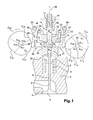
- FIG. 1 represents a first embodiment of a control device according to the invention, mounted on the cylinder head 1 of an internal combustion engine.
- the cylinder head 1 is conventionally equipped with at least one valve 2, for example an intake valve, comprising a head 3 held in abutment on a sealing seat 4 of the cylinder head 1, by a return spring 5.
- the valve 2 further comprises a rod 6 opposite to the head 3, supporting a cup 7 of support of one end of the return spring 5.
- the other end of the return spring is for example directly on the yoke 1.
- the device according to the invention comprises a body 8 fixed on the yoke 1, for example by screwing, and surrounding a cavity 9 communicating with the outside through four orthogonal cylinders 10, 11, 12, 13.
- a piston Ps is fixed to the free end of the rod 6 of the valve 2 and is slidably mounted in the first cylinder 10 of the body 8.
- the piston Ps is movable between a top dead center ( figure 1 ) for which the valve 2 is closed, that is to say rests on its seat 4, and a bottom dead point, for which the valve 2 is open at its maximum adjustable lift, that is to say is peeled of the seat 4.
- the pistons P1, P2 and Pa respectively called the opening piston, the closing piston and the shuttle piston, are slidably mounted respectively in the cylinders 11, 12 and 13 of the cavity 9.
- the pistons P1, P2, Pa and Ps delimit a portion of the cavity 9, filled with a substantially constant volume of incompressible fluid, such as oil, and whose sealing is ensured by the pistons P1, P2, Pa and Ps.
- the volume of fluid in the cavity 9 is the reference volume defined above, which does not evolve in operation, with the exception of possible leaks that can be compensated, as will be better described later.
- the pistons P1 and P2 are coaxial, as are the pistons Pa and Ps.
- the pistons P1 and P2 are furthermore oriented perpendicular to the pistons Pa and Ps.
- the piston Pa has an outer end 14, that is to say opposite to the cavity 9, comprising a flange 15 adapted to abut against an outer face 16 of the body 8 (internal abutment).
- the outer end 14 of the piston Pa is also able to bear against an external fixed stop 17 (external stop).
- the piston Pa is thus movable between its internal and external stops, a return spring 18 tending to push the shuttle piston Pa towards its internal stop.
- the shuttle piston Pa is movable between a top dead center, defined by the internal stop, and a bottom dead point, defined by the outer stop.
- the piston P1 is actuated by an opening cam C1, driven in rotation about an axis 19, by a first shaft (not shown).
- the piston P2 is actuated by a closure cam C2, driven in rotation about an axis 20, by a second shaft (not shown), synchronous and parallel to the first shaft and perpendicular to the section plane of the figure 1 .
- the axes 19, 20 intersect the common axis of the pistons P1 and P2.
- the direction of rotation of the cams C1, C2 is represented by arrows at the figure 1 and corresponds to the counterclockwise direction in this figure.
- the device according to the invention further comprises phase shift means (not shown) of the second shaft relative to the first shaft, or vice versa.
- the second shaft (and thus the closure cam C2) can be advanced in operation relative to the first shaft (and therefore with respect to the opening cam C1) up to a maximum phase shift angle.
- the outer ends of the pistons P1 and P2 comprise flanges 21, 22 cooperating with torsion springs 23, 24 mounted around fixed pins 25, 26 and tending to move the pistons P1 and P2 towards the outside of the cavity, c ' that is, towards their bottom dead center, so that the outer ends of the pistons P1 and P2 respectively bear on the opening cam C1 and closure C2, by means of rockers 27, 28 pivoting about fixed axes 29, 30 to avoid radial forces on the pistons P1 and P2.
- the opening C1 and closure C2 cams each comprise a base circle arc C11, C21 centered on the axis of rotation 19, 20 of each cam C1, C2 and a single lobe whose profile is constituted by a rising ramp C12, C22 making it possible to move the corresponding piston P1, P2 from its bottom dead center to its top dead center, followed by a second circular arc C13, C23 concentric with the base circle C11, C21 and of larger diameter than this one, to immobilize the opening pistons P1 and closing P2 at their top dead center, followed by a downward ramp C14, C24 to bring the opening pistons P1 and closing P2 to their neutral position low.
- the angular aperture ⁇ 11 of the basic circular arc C11 of the opening cam C1 is at least equal to the angular aperture ⁇ 22 of the rising ramp C22 of the closing cam C2, increased by the phase angle maximum between the first and second trees.
- the angular aperture ⁇ 21 of the basic circular arc C21 of the closing cam C2 is at least equal to the angular aperture ⁇ 14 of the descending ramp C14 of the aperture cam C1 increased by the angle maximum phase shift.
- the profile of each of the cams C1, C2 is continuous.
- the rising ramp C12 of the opening cam C1 and the downward ramp C24 of the closing cam C2 are so-called fast ramps.
- the rising ramp C22 of the closing cam C2 and the descending ramp C14 of the opening cam C1 are so-called slow ramps.
- the angular aperture ⁇ 12, ⁇ 24 of the fast ramps C12, C24 is smaller than the angular aperture ⁇ 14, ⁇ 22 of the slow ramps C14, C22
- the opening C1 and closure C2 cams are reversed in that the fast ramp C24 of the closing cam C2 is descending when the fast ramp C12 of the opening cam C1 is rising, and that the slow ramp C22 of the closure cam C2 is rising when the slow ramp C14 of the opening cam C1 is descending.
- the angular aperture ⁇ 13, ⁇ 23 of the second circular arcs C13, C23 is equal to that ⁇ 12, ⁇ 24 of the fast ramps C12, C24, in order to be able to reach the maximum lifting of the valve 2 of which the device is capable.
- the pistons P1 and P2 are identical and each move the same volume as the piston Pa between their bottom dead point and their top dead center. This volume is called common cylinder capacity.
- the stroke and the diameter of the piston Pa may be different from those of the pistons P1 and P2 to optimize the return spring 18 which generates in the cavity 9 a much lower pressure than that generated by the spring 5 of the valve 2, taking into account the the low inertia of the piston Pa and the slowness of the ramps C14 and C22.
- the return springs 18, 5 of the shuttle piston Pa and the valve 2 are such that the pressure of the fluid necessary for the displacement of the shuttle piston Pa to its bottom dead point is less than the pressure required to open the valve 2.
- the device according to the invention also comprises means of recalibration of the fluid reference volume in the cavity 9, comprising a supply conduit 32 in incompressible fluid equipped with a nonreturn valve 33 and connecting a source 34 of fluid under pressure at the cavity 9 (see Figures 4A and 5A ).
- the fluid pressure from the supply duct 32 is insufficient to move the piston Pa.
- recalibration means are known from the document WO 02/48510 , in the name of the Applicant.
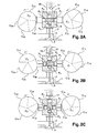
- FIGS 2A to 2E represent the different stages of the operation of the control device of the figure 1 during the duration of a cycle performed by a complete rotation of the cams C1 and C2.
- the cycle is represented for an intermediate phase shift cams C1 and C2, corresponding to an intermediate maximum lift of the valve 2 (see for example the curve 5 at the figure 3 ).
- the Figure 2A represents the device at the end of the recalibration phase of the fluid reference volume in the cavity 9, via the aforementioned recalibration means.
- the pistons P1 and P2 are at the bottom dead center on the base circle C11, C21 of the cams C1 and C2, the pistons Ps and Pa being at high dead point under the action of the return springs 5 and 18.
- the rotation of the cams C1, C2 thus produces no movement of the pistons and the hydraulic fluid in the cavity 9.
- the Figure 2B represents the device during the second phase of the cycle, called the arming phase, where the piston P1 remains stationary at its bottom dead point on the base circle C11 of the cam C1 when the piston P2, on the slow rising ramp C22 of the C2 cam drives into the cavity 9 a first common cylinder of fluid that pushes the shuttle piston Pa, the latter passing from its top dead center to its bottom dead stop by raising the pressure in the cavity 9 to compress the return spring 18 Pa piston.
- the Figure 2C represents the device at the end of the third phase of the cycle, said opening of the valve 2, where the valve 2 reaches its maximum lift, when the piston P1, on the fast ramp C12 of the cam C1, pushes in the cavity 9 a second common cylinder of fluid and that the piston P2 on the rapid descending ramp C24 of the cam C2 sucks a fraction of the volume discharged by P1 to limit the volume of fluid that pushes the piston Ps and to reduce the maximum lift of the valve 2 reached when the remaining volume to be discharged by the piston P1 is equal to the volume already sucked by the piston P2.
- the 2D figure represents the device at the end of the fourth phase of the so-called closing cycle of the valve 2, where the piston P1 is immobilized at its top dead center on the second circular arc C13 of the cam C1 when the piston P2, on the C24 fast descending ramp of the C2 cam sucks the fluid discharged by the piston Ps under the action of the return spring 5 which closes the valve 2.
- the figure 2E represents the device during the fifth phase of the disarming cycle, where the valve 2 has fallen back on its seat 4 and the piston Ps has found its top dead center, where the piston P2 has found its low dead point and where the piston P1 on the slow descending ramp C14 of the cam C1 sucks the common cylinder discharged by the piston Pa under the action of its return spring 18 to disarm the device and return to the position of the Figure 2A from which a new cycle can be approached.
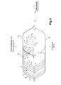
- FIG 3 shows an operating diagram of the device of the figure 1 whose abscissae represent the angle of rotation of the cams C1, C2 between the beginning and the end of a cycle, whose positive ordinates represent the volume of fluid discharged by the piston P1 (bold line), the volume of fluid discharged by the piston P2 (thin line) and the volume of fluid absorbed by the piston Ps of the valve 2 (dotted), and whose negative ordinate represents the volume of fluid absorbed by the shuttle piston Pa.
- the curves numbered 1 to 7 correspond to seven successive phase shifts between the shafts, the first curve 1 corresponding to a zero angle where the valve 2 is wide open and the last curve 7 corresponds to a phase shift of 50 degrees, for which the valve 2 no longer opens.
- the dotted curves thus also illustrate the lifting laws of the valve 2 for the seven phase shifts. It is recalled that the lifting of a valve 2 is the distance between the range of its head 3 and the seat 4 of the cylinder head 1.
- control device allows, in operation and by adjusting the phase shift between the two shafts, to adjust the maximum lift of the valve 2 and, simultaneously, to shift the closing angle of the valve 2 so as to adjust the duration angular opening of the valve 2 and, if necessary, to keep the valve 2 closed for the duration of a cycle.
- the relative angular setting of the shafts is defined in such a way that, for a zero phase shift angle (curve 1), the closure piston P2 leaves its top dead center at the same time that the opening piston P1 reaches its own, so that the maximum lifting of the valve 2 which is capable of the device is reached for a single angle of the cycle.
- the device may comprise means for erasing the abutment 17 of the bottom dead center of the shuttle piston Pa (shown schematically in FIG. figure 1 by an arrow 56), so that the piston Pa can suck the algebraic sum of the volumes of fluid discharged by the opening piston P1 and the closing piston P2, in order to prevent the arming of the device whatsoever the phase shift angle between the opening shaft and the closing shaft.
- FIGS. 4A and 4B illustrate a control device according to a second embodiment of the invention, for the synchronous actuation of two identical or twin valves 2a, 2b, via three cams C1a, C1b and C2, so as to ensure a hydraulic symmetry of the device.
- twin valves 2a, 2b have parallel axes and are actuated by two coaxial shafts 35, 36, whose axis is in the plane of the axes of the valves 2a, 2b and perpendicular to said axes, respectively carrying two cams of openings C1a, C1b a closure cam C2.
- the cams of openings C1a, C1b are arranged symmetrically on either side of the closure cam C2.
- the identical profiles of the cams C1 a, C1b and that of the cam C2 are similar to those described above.
- the body 8 has a cavity 9 and a plane of symmetry BB '.
- the cavity 9 opens outwards by six cylinders, respectively two parallel symmetrical cylinders 10a, 10b parallel to which slide two pistons Psa, Psb fixed on the free ends of the stems of the valves 2a, 2b, two other symmetrical cylinders 11a, 11b parallel to each other , where two opening pistons P1a, P1b slide, a first central cylinder 12 in which slides a closing piston P2, and a second perpendicular central cylinder 13 in which a shuttle piston Pa slides.
- the pistons Psa, Psb of the valves 2a, 2b, the opening pistons P1a, P1b and the closing piston P2 are parallel to each other.
- the shuttle piston Pa is orthogonal to the aforementioned pistons Psa, Psb, P1a, P1b, P2.
- the axis of the closing piston P2 and the axis of the shuttle piston Pa are located in the plane of symmetry BB 'of the body 8.
- the shuttle piston Pa is movable between inner and outer stops 16 and 17 respectively defining its top and bottom dead spots, a return spring 18 tending to push it towards its internal abutment 16.
- the return springs 18, 5a, 5b of the shuttle piston Pa and the valves 2a, 2b are such that the pressure of the fluid necessary for the displacement of the shuttle piston Pa to its bottom dead point is less than the pressure required to open the any of the valves 2a, 2b.
- the two opening cams C1a, C1b are identical, as are the two opening pistons P1a, P1b, that the two valve pistons Psa, Psb, that the two valves 2a, 2b and that the springs of recall 5a, 5b.
- the control device is thus symmetrical with respect to the plane BB '.
- each valve 2a, 2b comprises a head 3a, 3b intended to rest on a seat 4a, 4b of a yoke 4 on which is fixed the body 8, for example by screwing.
- Each cam C1a, C1b, C2 actuates the corresponding piston P1a, P1b, P2 via a pawl 27a, 27b, 28, pivoting about an axis 29a, 29b 30.
- the opening pistons P1 a, P1 b and P2 closing are maintained in contact with the latches 27a, 27b, 28, and the latches 27a, 27b, 28 are maintained in contact with the cams C1a, C1b, C2, through the springs of recall 23a, 23b, 24 tending to move the pistons P1a, P1b, P2 to their bottom dead center.
- the closing cam C2 is integral with the internal shaft 36, the latter being coupled to the coaxial outer shaft 35 carrying the opening cams C1a, C1b, via a not shown phase shifter.
- phase shifter is well known from the state of the art and will not be detailed here.
- the closing cam C2 is secured to the internal shaft 36 by a pin 37 which passes through the outer shaft 35 by two oblong slots 38 allowing the desired phase variation.
- the volume displaced by the closing piston P2 and the shuttle piston Pa is equal to twice the volume displaced by each opening piston P1a, P1b.
- the cavity 9 also communicates with a fluid source 34 under pressure via a duct 32 equipped with a unidirectional valve 33 oriented in the plane of symmetry BB '.
- the opening and closing flows of the twin valves 2a, 2b run on identical hydraulic paths, which guarantees the synchronism of the valves 2a, 2b provided that their return springs 5a , 5b are perfectly identical.
- the control device is housed inside a camshaft support 50 fixed on the yoke 1, for example by screwing.
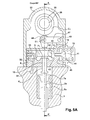
- FIGS. Figures 5A and 5B A control device according to a third embodiment is shown in FIGS. Figures 5A and 5B .
- This aims to mechanically ensure the synchronism of two twin valves 2a, 2b whose return springs 5a, 5b are not perfectly identical, from an asymmetrical hydraulic circuit activated by two cams only.
- twin valves 2a, 2b have parallel axes and are actuated, via a spreader 39, by two coaxial shafts, respectively external 35 and internal 36, respectively carrying an opening cam C1 and a closing cam C2.
- the profiles of the cams C1, C2 are similar or identical to those described above.
- the body 8 has a cavity 9 and a plane of symmetry BB '.
- the cavity 9 opens outwards by four cylinders, respectively a cylinder 10 which slides a piston Ps formed by a part of the spreader bar 39 ( Figure 5B ), a cylinder 11 in which slides an opening piston P1, a cylinder 12 in which a closing piston P2 slides, and a cylinder 13 in which a shuttle piston Pa slides.
- the opening piston P1, the closing piston P2 are parallel. between them.
- the shuttle piston Pa is, for example, orthogonal to the aforementioned pistons P1, P2, Ps.
- the shuttle piston Pa and the piston Ps of the spreader bar 39 have their axes in the plane of symmetry BB 'of the body 8.
- the opening pistons P1 and P2 closing pistons are identical and are arranged on either side of the plane of symmetry BB 'of the body 8.
- the shuttle piston Pa is movable between two stops, respectively defining its top and bottom dead spots, a return spring 18 tending to push it towards its top dead center.
- the shuttle piston Pa is formed of two parts 40, 41 assembled to each other, for example by screwing, a first part 40 comprising a flange 42 intended to abut against an internal sealing seat 43 of the cylinder 13, so as to define the bottom dead stop and limit leakage, a second portion 41 having a flange 44 intended to abut against an outer wall 45 of the body 8, so as to define the stop point dead high.
- the return springs 18, 5a, 5b of the shuttle piston Pa and the valves 2a, 2b are such that the pressure of the fluid necessary for the displacement of the shuttle piston Pa to its bottom dead point is less than the pressure required to open the valves 2a, 2b.
- each valve 2a, 2b comprises a head 3a, 3b intended to rest on a seat 4a 4b of a yoke 1 on which is fixed the body 8, for example by screwing.
- the free ends of the rods of the valves 2a, 2b each bear on a flange 46a, 46b of the spreader 39.
- the spreader 39 has a central portion intended to form the piston Ps mounted in the cylinder 10 of the body 8, and two symmetrical wings 46a, 46b extending laterally on either side of the central portion. The movement of the spreader 39 thus causes the synchronous movement of the twin valves 2a, 2b, even if the return springs 5a, 5b of said valves 2a, 2b are not perfectly identical.
- Each cam C1, C2 actuates the corresponding piston P1, P2 through an articulated roller rocker arm.
- Each rocker arm has an arm 47 pivoting about a fixed axis 49 and carrying the axis 51 of a roller 48 in contact with the cam.
- Each rocker arm further comprises a clevis articulated on the axis 51 of the roller 48, comprising two lateral branches 52 extending on either side of the roller 48 and traversed by the shaft 51, and a central branch 53, solidarizing the lateral branches 52, and carrying a rod the end comprises a sphere 54 trapped in a complementary spherical housing 55 formed in the corresponding piston P1, P2, so as to form a ball joint connection between the yoke and the corresponding piston P1, P2.
- rollers 48 are held in contact with the cams C1, C2, by means of return springs, not shown.
- the inner shaft 36 is coupled to the coaxial outer shaft via a not shown phase shifter.
- the closure cam C2 is secured to the internal shaft 36 by a pin 37 which passes through the outer tube 35 by two oblong slots allowing the desired phase variation.
- the volumes displaced by the opening piston P1, the closing piston P2 and the shuttle piston Pa are equal to each other.
- the cavity 9 also communicates with a source of fluid 34 under pressure, via a duct 32 equipped with a unidirectional valve 33.
- control device is housed inside a camshaft support 50 fixed on the yoke 1, for example by screwing.
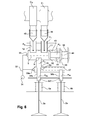
- figure 6 represents two parallel twin valves 2a, 2b whose lifts are equal.
- a control device is identical to the previous one to the cylinder 10 where the piston Ps slides.
- the body 8 comprises an additional non-deformable hydraulic cavity 57 communicating with the cavity 9 via the cylinder 10 and communicating with the outside via a cylinder 58a, of axis parallel to the cylinder 10, and preferably coaxial with the cylinder 10, and via a cylinder 58b which is not necessarily parallel to the cylinder 58a.
- a piston Ps slides in the cylinder 10 and is integral with a piston Psa, of smaller diameter (half section in the figure), which slides in the cylinder 58a and is integral and parallel to the valve stem 2a.
- the cavity 57 closed by the pistons Ps, Psa, Psb contains a constant volume of hydraulic fluid equal to its volume when the valves 2a and 2b rest on their seats in the closed position.
- the cavity 57 communicates with the pressure source 34 via a nonreturn valve 33a.
- the piston Ps activates the valve 2a via the piston Psa, the assembly being mechanically secured and therefore having the same stroke.
- the operating clearance of the valve 2a is canceled by the valve 33.
- the piston Ps delivers a volume of oil proportional to the difference in section between the pistons Ps in the cavity 57. and Psa which is absorbed by the displacement of the piston Psb which actuates the valve 2b.
- the operating clearance of the valve 2b is canceled by the valve 33a.
- This embodiment allows the piston Ps to move the valves 2a and 2b in synchronism with different lifts and non-parallel axes of movement.
- the lifting of the valve 2b is equal to that of the valve 2a multiplied by the ratio between the section difference Ps-Psa and the section Psb.
Description
La présente invention concerne de façon générale un dispositif de commande d'au moins une soupape, par exemple pour un moteur alternatif et de façon plus particulière un dispositif de commande variable d'au moins une soupape actionnée par au moins deux cames portées par des arbres synchrones et déphasables angulairement l'un par rapport à l'autre. L'invention s'applique notamment à la distribution variable en fonctionnement d'un moteur alternatif dont la culasse porte deux arbres à cames coaxiaux reliés par un déphaseur, par exemple hydraulique.The present invention generally relates to a device for controlling at least one valve, for example for an alternating motor and, more particularly, a device for variable control of at least one valve actuated by at least two cams carried by shafts. synchronous and dephasable angularly relative to each other. The invention applies in particular to the variable distribution in operation of an alternating motor whose head carries two coaxial camshafts connected by a phase shifter, for example hydraulic.
Par distribution on entend, de façon classique, l'ensemble des séquences d'ouverture et de fermeture des soupapes du moteur.By distribution means, in a conventional manner, all the opening and closing sequences of the engine valves.
On sait que les performances des moteurs alternatifs sont très dépendantes des positions angulaires du vilebrequin pour lesquelles les soupapes s'ouvrent et se ferment dans le cycle du moteur, et que le diagramme de distribution optimal change avec les conditions de fonctionnement, et, en particulier avec le régime et la charge. Cette distribution influence les taux de compression et de détente effectifs (cycles de Miller), la quantité de gaz brûlés éventuellement recyclée, l'énergie disponible dans les gaz d'échappement, le rendement volumétrique, les frottements mécaniques etc. Il est donc souhaitable de pouvoir modifier indépendamment, pendant le fonctionnement du moteur, les positions angulaires du vilebrequin pour lesquelles s'effectuent l'ouverture et la fermeture des soupapes d'admission et d'échappement.It is known that the performance of the reciprocating engines is very dependent on the angular positions of the crankshaft for which the valves open and close in the cycle of the engine, and that the optimal distribution diagram changes with the operating conditions, and in particular with the diet and the load. This distribution influences the effective compression and expansion rates (Miller cycles), the amount of flue gases possibly recycled, the energy available in the exhaust gas, the volumetric efficiency, the mechanical friction, etc. It is therefore desirable to be able to independently modify, during the operation of the engine, the angular positions of the crankshaft for which the opening and closing of the intake and exhaust valves take place.
De plus, la levée des soupapes d'admission conditionne largement le niveau de turbulence dans la chambre de combustion et il peut être avantageux de régler la puissance d'un moteur à allumage commandé en laminant le flux d'admission au niveau du siège des soupapes d'admission plutôt qu'au niveau d'un papillon disposé en amont d'un collecteur d'admission.In addition, the lift of the intake valves largely determines the level of turbulence in the combustion chamber and it may be advantageous to adjust the power of a spark-ignition engine by rolling the intake flow at the seat of the valves. rather than at the level of a butterfly disposed upstream of an intake manifold.
En dernier lieu, il peut être avantageux de désactiver certains cylindres d'un moteur en maintenant fermées leurs soupapes d'admission et/ou leurs soupapes d'échappement pendant certaines phases de fonctionnement du moteur.Finally, it may be advantageous to disable some engine cylinders by keeping their intake valves and / or their exhaust valves closed during certain phases of engine operation.
Dans le cas où les soupapes sont actionnées par des arbres à cames, lesdites soupapes sont appuyées, via des mécanismes oscillants ou coulissants par des ressorts de rappel, sur des cames rotatives dont le profil impose la cinématique des mouvements de translation alternatifs desdites soupapes. Pour éviter les chocs, les contacts entre les éléments de la chaine mécanique reliant les cames et les soupapes ne doivent pas être rompus, et les soupapes doivent atterrir sur leur siège avec une vitesse quasi nulle.In the case where the valves are actuated by camshafts, said valves are supported, via mechanisms oscillating or sliding by return springs, on rotating cams whose profile imposes the kinematics of reciprocating translational movements of said valves. To avoid shocks, the contacts between the elements of the mechanical chain connecting the cams and the valves must not be broken, and the valves must land on their seat with a speed almost zero.
La plupart des dispositifs variables utilisés à ce jour génèrent le mouvement d'une soupape à partir du profil d'une seule came que l'on déforme mécaniquement ou hydrauliquement.Most of the variable devices used to date generate the movement of a valve from the profile of a single cam that is deformed mechanically or hydraulically.
La complexité des dispositifs connus pour faire varier mécaniquement la durée et la levée des soupapes (tel que le dispositif « Valvetronic » faisant notamment l'objet du brevet
Les dispositifs électro-hydrauliques (tels que le dispositif « Uniair » décrit notamment dans les brevets
D'autres dispositifs génèrent le mouvement d'une soupape à partir des profils de deux cames déphasables, généralement portées par deux arbres coaxiaux, dont l'une assure l'ouverture de la soupape et l'autre la fermeture.Other devices generate the movement of a valve from the profiles of two cams dephasable, usually carried by two coaxial shafts, one of which ensures the opening of the valve and the other closing.
La demande de brevet
La présente invention, qui s'appuie sur le même principe vise à offrir les mêmes fonctionnalités que les meilleurs dispositifs connus, à partir d'un simple déphaseur rotatif reliant deux arbres à cames synchrones.The present invention, which is based on the same principle aims to offer the same functionality as the best known devices, from a simple rotary phase shifter connecting two synchronous camshafts.
Le but principal de la présente invention est donc de pouvoir régler en fonctionnement la durée angulaire d'ouverture d'au moins une soupape ainsi que sa levée jusqu'à sa fermeture totale, sans perdre, par laminage d'un fluide hydraulique, l'énergie accumulée dans les moyens de rappel du dispositif.The main object of the present invention is therefore to be able to adjust in operation the angular duration of opening of at least one valve and its lifting until its total closure, without losing, by rolling a hydraulic fluid, the energy accumulated in the return means of the device.
A cet effet, l'invention propose un dispositif de commande d'au moins une soupape, par exemple pour un moteur alternatif, animée d'un mouvement alternatif de translation rectiligne destiné à ouvrir ou fermer un orifice muni d'un siège d'étanchéité, ladite soupape comportant un moyen de rappel élastique vers une position de fermeture, le dispositif comportant un corps comprenant une cavité indéformable communiquant exclusivement avec l'extérieur par au moins quatre cylindres rectilignes fermés respectivement par quatre pistons déplaçables en mouvement alternatif entre un point mort bas éloigné de l'intérieur de la cavité et un point mort haut rapproché de l'intérieur de la cavité, caractérisé en ce que lesdits pistons sont un piston relié mécaniquement à la soupape et antagoniste à son moyen de rappel, un piston d'ouverture actionné par une came d'ouverture entraînée en rotation par un premier arbre, un piston de fermeture actionné par une came de fermeture entraînée en rotation par un second arbre tournant en synchronisme avec le premier arbre et pouvant être décalé par rapport au premier arbre d'un angle réglable en fonctionnement, un piston navette se déplaçant entre une première butée fixe définissant le point mort bas et une seconde butée fixe définissant le point mort haut, vers laquelle le piston navette est rappelé par un moyen élastique, en ce que la portion de la cavité délimitée par les pistons est remplie par un volume de référence constant de fluide hydraulique sensiblement incompressible défini quand la soupape repose sur son siège, que les pistons d'ouverture et de fermeture sont à leur point mort bas et que le piston navette est à son point mort haut, en ce que le piston d'ouverture, le piston de fermeture et le piston navette ont une cylindrée commune et déplacent le même volume de fluide entre leur point mort bas et leur point mort haut, et en ce que les moyens de rappel élastiques du piston navette et de la soupape sont tels que la pression du fluide nécessaire au déplacement du piston navette jusqu'à son point mort bas est inférieure à la pression nécessaire pour ouvrir la soupape.For this purpose, the invention proposes a device for controlling at least one valve, for example for an alternating motor, driven by reciprocating rectilinear movement intended to open or close an orifice provided with a sealing seat. , said valve comprising an elastic return means to a closed position, the device comprising a body comprising a non-deformable cavity communicating exclusively with the outside by at least four straight cylinders respectively closed by four reciprocable pistons in reciprocating motion between a bottom dead center remote from the interior of the cavity and a top dead center close to the inside of the cavity, characterized in that said pistons are a piston mechanically connected to the valve and antagonistic to its return means, an actuated opening piston by an opening cam driven in rotation by a first shaft, a closing piston actuated by a closing cam e driven in rotation by a second shaft rotating in synchronism with the first shaft and displaceable relative to the first shaft by an adjustable angle in operation, a shuttle piston moving between a first fixed stop defining the bottom dead center and a second fixed stop defining the top dead center towards which the shuttle piston is returned by a means elastic, in that the portion of the cavity delimited by the pistons is filled by a constant reference volume of substantially incompressible hydraulic fluid defined when the valve rests on its seat, that the opening and closing pistons are in their neutral position bottom and that the shuttle piston is at its top dead center, in that the opening piston, the closing piston and the shuttle piston have a common displacement and move the same volume of fluid between their bottom dead point and their neutral position high, and in that the elastic return means of the shuttle piston and the valve are such that the pressure of the fluid required to move the shuttle piston to its bottom dead point is less than the pressure required to open the valve.
Dans le dispositif conforme à l'invention, un cycle de travail correspondant à une ouverture-fermeture de la soupape s'effectue sur une rotation complète des arbres synchrones qui entraînent les cames d'ouverture et de fermeture de la soupape. Le cycle commence et s'achève dans une configuration de repos du dispositif qui définit le volume de référence de fluide hydraulique présent dans la cavité. Dans la configuration de repos, la soupape est rappelée sur son siège par des moyens élastiques, le piston Ps de la soupape est à son point mort haut, le piston navette Pa est rappelé sur sa seconde butée par le moyen élastique correspondant et est à son point mort haut, et les pistons d'ouverture P1 et de fermeture P2 sont à leur point mort bas, ces derniers étant définis par les cercles de base des cames d'ouverture C1 et de fermeture C2.In the device according to the invention, a working cycle corresponding to an opening-closing of the valve is performed on a complete rotation of the synchronous shafts which drive the cams opening and closing the valve. The cycle begins and ends in a rest configuration of the device that defines the reference volume of hydraulic fluid present in the cavity. In the rest configuration, the valve is returned to its seat by elastic means, the piston Ps of the valve is at its top dead point, the shuttle piston Pa is returned to its second stop by the corresponding elastic means and is at its top dead center, and the opening piston P1 and closing P2 are at their bottom dead point, the latter being defined by the base circles of the opening cams C1 and closure C2.
Pendant la rotation des arbres, la course des pistons d'ouverture P1 et de fermeture P2 dépend uniquement de la position angulaire des cames C1 et C2 conformément à leurs profils respectifs. Un vilebrequin entraînant les cames peut ainsi commander le débit de fluide instantané positif ou négatif refoulé dans la cavité par les pistons P1 et P2 et, en conséquence, le débit global instantané qui alimente la cavité, égal à la somme algébrique des débits instantanés refoulés par P1 et P2. Les pistons P1 et P2 se trouvant simultanément à leur point mort bas au commencement d'un cycle, le volume global refoulé dans la cavité par les pistons P1 et P2 depuis le début du cycle se situe à tout moment entre zéro et deux fois la cylindrée commune des pistons P1, P2 et Pa pendant toute la durée du cycle. Le volume de référence de fluide hydraulique présent dans la cavité restant constant, le débit global refoulé par les pistons P1 et P2 depuis leur point mort bas doit être absorbé par les pistons Pa et Ps qui se trouvaient à leur point mort haut au début du cycle. Compte tenu du tarage de leurs moyens de rappel respectifs, le débit global refoulé est exclusivement absorbé par le piston navette Pa tant que ledit débit reste inférieur à la cylindrée commune précitée. Le piston Ps ne peut donc absorber que le débit refoulé dépassant ladite cylindrée commune, excédent qui ne peut plus être absorbé par le piston navette Pa, dès lors que ce piston a atteint sa première butée à son point mort bas. Le piston Ps de la soupape ne peut donc absorber qu'un volume compris entre zéro et ladite cylindrée commune. On constate que la phase de déplacement du piston navette Pa, de son point mort haut à son point mort bas, constitue une phase d'armement du dispositif préalable à tout déplacement de la soupape.During the rotation of the shafts, the stroke of the opening pistons P1 and closing P2 depends solely on the angular position of the cams C1 and C2 according to their respective profiles. A crankshaft driving the cams can thus control the flow of positive or negative instantaneous fluid discharged into the cavity by the pistons P1 and P2 and, consequently, the instantaneous total flow rate that supplies the cavity, equal to the algebraic sum of the instantaneous flow rates discharged by P1 and P2. The pistons P1 and P2 being simultaneously at their bottom dead point at the beginning of a cycle, the overall volume discharged into the cavity by the pistons P1 and P2 from the beginning of the cycle is at any time between zero and twice the common cylinder capacity of the pistons P1, P2 and Pa for the duration of the cycle. Since the reference volume of hydraulic fluid present in the cavity remains constant, the global flow delivered by the pistons P1 and P2 from their bottom dead point must be absorbed by the pistons Pa and Ps which were at their top dead center at the beginning of the cycle. . Given the calibration of their respective biasing means, the total flow discharged is exclusively absorbed by the shuttle piston Pa as said flow rate remains lower than the aforementioned common displacement. The piston Ps can therefore absorb only the discharged flow exceeding said common displacement, which can no longer be absorbed by the shuttle piston Pa, since the piston has reached its first stop at its bottom dead point. The piston Ps of the valve can therefore absorb a volume between zero and said common cylinder. It can be seen that the displacement phase of the shuttle piston Pa, from its top dead center to its bottom dead point, constitutes an arming phase of the device prior to any displacement of the valve.
Pour modifier la distribution, on dispose d'un angle de déphasage maximal autorisé par le déphaseur pour, par exemple, avancer en fonctionnement le second arbre par rapport au premier arbre, les cames d'ouverture et de fermeture comportant chacune un arc de cercle de base et un lobe unique dont le profil est constitué par une rampe montante permettant de déplacer le piston correspondant de son point mort bas jusqu'à son point mort haut, suivie d'un second arc de cercle concentrique au cercle de base et de plus grand diamètre que celui-ci, permettant d'immobiliser les pistons d'ouverture et de fermeture à leur point mort haut, suivi d'une rampe descendante permettant de ramener les pistons d'ouverture et de fermeture vers leur point mort bas, l'ouverture angulaire de l'arc de cercle de base de la came d'ouverture étant au moins égale à l'ouverture angulaire de la rampe montante de la came de fermeture, augmentée de l'angle de déphasage maximum, l'ouverture angulaire de l'arc de cercle de base de la came de fermeture étant au moins égale à l'ouverture angulaire de la rampe descendante de la came d'ouverture augmentée de l'angle de déphasage maximum.To modify the distribution, it has a maximum phase shift angle allowed by the phase shifter to, for example, advance the second shaft in operation relative to the first shaft, the opening and closing cams each having a circular arc of base and a single lobe whose profile is constituted by a rising ramp for moving the corresponding piston from its bottom dead center to its top dead center, followed by a second circular arc concentric to the base circle and larger diameter that it, to immobilize the opening and closing pistons to their top dead center, followed by a downward ramp to bring the opening and closing pistons to their bottom dead center, the opening angularly of the base arc of the opening cam being at least equal to the angular aperture of the rising ramp of the closing cam, increased by the maximum phase shift angle, the angular aperture of the basic circle arc of the closing cam being at least equal to the angular aperture of the down ramp of the aperture cam increased by the maximum phase shift angle.
Selon une caractéristique de l'invention, sur la totalité de la plage de déphasage, le calage angulaire relatif des premier et second arbres est tel que le piston d'ouverture quitte son point mort bas sous l'action de la rampe montante de la came d'ouverture, après que le piston navette ait atteint son point mort haut sous l'action de la rampe montante de la came de fermeture, et que le piston de fermeture atteigne son point mort bas sous l'action de la rampe descendante de la came de fermeture avant que le piston d'ouverture quitte son point mort haut sous l'action de la rampe descendante de la came d'ouverture.According to one characteristic of the invention, over the entire range of phase shift, the relative angular setting of the first and second shafts is such that the opening piston leaves its bottom dead point under the action of the rising ramp of the cam opening, after the shuttle piston has reached its top dead point under the action of the rising ramp of the closing cam, and that the closing piston reaches its bottom dead point under the action of the downward ramp of the closing cam before the opening piston leaves its top dead center under the action of the downward ramp of the opening cam.
Dans ces conditions, à partir de la position de repos, la rampe montante de la came de fermeture C2 entame le cycle de travail en déplaçant le piston de fermeture P2 de son point mort bas à son point mort haut en refoulant dans la cavité une cylindrée commune de fluide pour repousser, sans choc, le piston navette Pa de son point mort haut à son point mort bas et armer ainsi le dispositif. Pendant cette phase, le piston P1 demeure à son point mort bas défini par le cercle de base de la came C1 et le piston Ps demeure à son point mort haut. Le piston P2 reste ensuite immobilisé à son point mort haut, défini par le second arc de cercle de la came C2, quand la rampe montante de la came C1 assure la phase suivante en déplaçant le piston P1 de son point mort bas vers son point mort haut pour refouler dans la cavité une deuxième cylindrée commune de fluide hydraulique nécessaire à l'ouverture de la soupape.Under these conditions, from the rest position, the rising ramp of the closure cam C2 starts the work cycle by moving the closing piston P2 from its bottom dead point to its top dead center by driving a displacement in the cavity. common fluid to repel, without shock, the shuttle piston Pa from its top dead center to its lowest dead point and thus arm the device. During this phase, the piston P1 remains at its bottom dead point defined by the base circle of the cam C1 and the piston Ps remains at its top dead center. The piston P2 then remains immobilized at its top dead point, defined by the second arc of the cam C2, when the rising ramp of the cam C1 ensures the next phase by moving the piston P1 from its bottom dead center to its neutral position high to discharge into the cavity a second common cylinder of hydraulic fluid required to open the valve.
Selon une forme de réalisation de l'invention, le calage angulaire relatif des arbres est défini de telle manière que, pour un angle de déphasage nul entre les premier et second arbres, qui correspond à la durée maximale d'ouverture de la soupape, le piston de fermeture quitte son point mort haut après que le piston d'ouverture ait atteint le sien, de manière à créer une plage initiale de déphasage pour laquelle la soupape stationne un certain temps à sa levée maximale entre ses phases d'ouverture et de fermeture.According to one embodiment of the invention, the relative angular setting of the shafts is defined in such a way that, for a zero phase angle between the first and second shafts, which corresponds to the maximum opening time of the valve, the closing piston leaves its top dead center after the opening piston has reached its, so as to create an initial range of phase shift for which the valve parks for a while at maximum lift between its opening and closing phases.
Pour cette configuration de l'invention, le piston P1 atteint son point mort haut avant que le piston P2 quitte le sien avec pour conséquence l'aspiration de la totalité de la cylindrée commune de fluide par le seul piston Ps qui ouvre la soupape jusqu'à la plus grande levée permise par le dispositif, qu'elle conserve jusqu'à ce que le piston P2 quitte son point mort haut, par l'effet de la rampe descendante de la came C2, en absorbant le débit refoulé par Ps pendant la fermeture de la soupape.For this configuration of the invention, the piston P1 reaches its top dead center before the piston P2 leaves its own, with the result that the entire common fluid cylinder is sucked by the single piston Ps which opens the valve until at the greatest lift allowed by the device, which it keeps until the piston P2 leaves its top dead center, by the effect of the downward ramp of the cam C2, absorbing the flow rate discharged by Ps during the closing the valve.
Selon une autre forme de réalisation de l'invention le calage relatif des arbres est défini de telle manière que, pour un angle de déphasage nul entre les premier et second arbres, le piston de fermeture quitte son point mort haut avant que le piston d'ouverture atteigne le sien.According to another embodiment of the invention, the relative setting of the shafts is defined in such a way that, for a zero phase shift angle between the first and second shafts, the closing piston leaves its top dead center before the piston of opening reaches his.
Dans ces conditions, avant la fin de la course de refoulement du piston P1, le piston P2 commence à aspirer une fraction croissante du débit refoulé par le piston P1 en diminuant de ce fait le débit global aspiré par le piston Ps et donc la levée maximale de la soupape, cette dernière n'étant atteinte que pour un seul angle de rotation des arbres et non pour une certaine période angulaire de rotation des arbres.Under these conditions, before the end of the discharge stroke of the piston P1, the piston P2 begins to suck up an increasing fraction of the flow delivered by the piston P1 thereby decreasing the overall flow sucked by the piston Ps and thus the maximum lift of the valve, the latter being reached only for a single angle of rotation of the trees and not for a certain angular period of rotation of the shafts.
Selon une forme de réalisation de l'invention permettant la fermeture totale de la soupape, l'angle de déphasage maximum de la came de fermeture par rapport à la came d'ouverture est suffisant pour que le piston de fermeture quitte son point mort haut avant que le piston d'ouverture quitte son point mort bas et que, à tout instant de la phase d'ouverture de la soupape, le volume de fluide aspiré par le piston de fermeture depuis son point mort haut soit supérieur au volume de fluide refoulé par le piston d'ouverture depuis son point mort bas, de manière à ce que, le débit global refoulé demeurant inférieur ou égal à la cylindrée commune, la soupape reste fermée pendant toute la durée du cycle et que le piston navette quitte et rejoigne son point mort bas pour maintenir le volume de la cavité à sa valeur de référence.According to one embodiment of the invention allowing the valve to close completely, the maximum phase angle of the closing cam relative to the opening cam is sufficient for the closing piston to leave its top dead center. that the opening piston leaves its low dead point and that, at any time during the opening phase of the valve, the volume of fluid sucked by the closing piston from its top dead center is greater than the volume of fluid discharged by the opening piston from its bottom dead point, so that, the total discharged flow remaining lower than or equal to the common cylinder capacity, the valve remains closed for the duration of the cycle and that the shuttle piston leaves and reaches its point death down to maintain the volume of the cavity at its reference value.
De cette manière, il est possible de déphaser les cames C1 et C2 de façon à ce que le débit global refoulé par les pistons P1 et P2 reste inférieur à la cylindrée commune et que le dispositif soit désarmé sur toute la durée du cycle, sans pouvoir déplacer la soupape à laquelle se substitue le piston Pa qui quitte et rejoint sa butée de point mort bas pour maintenir le volume de la cavité à sa valeur de référence.In this way, it is possible to phase shift the cams C1 and C2 so that the total flow delivered by the pistons P1 and P2 remains lower than the common cylinder capacity and the device is disarmed throughout the cycle, without being able to move the valve to which the piston Pa replaces which leaves and rejoins its bottom dead stop to maintain the volume of the cavity at its reference value.
La durée angulaire d'ouverture de la soupape ainsi que sa levée peut être réglée en fonctionnement, en modifiant l'angle de déphasage du second arbre et en maintenant fixe le premier arbre, ou inversement, ou encore en modifiant simultanément l'angle de déphasage de chacun des arbres par rapport à un vilebrequin entraînant lesdits arbres.The angular duration of opening of the valve and its lifting can be adjusted during operation, by modifying the phase shift angle of the second shaft and by holding the first shaft fixed, or conversely, or by simultaneously modifying the phase angle each of the shafts relative to a crankshaft driving said shafts.
Entre le déphasage nul où la soupape atteint sa durée d'ouverture et sa levée maximales et le déphasage maximal où la soupape ne s'ouvre pas, la durée angulaire d'ouverture est une fonction décroissante continue de l'angle de déphasage entre les arbres. La levée est aussi une fonction décroissante dudit angle de déphasage, la levée maximale pouvant éventuellement être maintenue pendant une période angulaire initiale de rotation des arbres comme indiqué précédemment. L'invention permet donc de régler la durée angulaire d'ouverture et permet aussi de régler la levée correspondante de la soupape entre une valeur nulle et une valeur maximale.Between the zero phase shift where the valve reaches its maximum opening time and its maximum lift and the maximum phase shift where the valve does not open, the opening angular duration is a continuous decreasing function of the phase angle between the shafts. . The lift is also a decreasing function of said phase shift angle, the maximum lift possibly being maintained during an initial angular period of rotation of the shafts as indicated above. The invention thus makes it possible to adjust the angular duration of opening and also makes it possible to adjust the corresponding lift of the valve between a zero value and a maximum value.
Si on dispose d'un seul déphaseur, on peut choisir entre un début d'ouverture fixe et une fin de fermeture variable, ou inversement. Si on dispose de deux déphaseurs, on peut régler simultanément le début d'ouverture et la fin de fermeture de la soupape.If we have a single phase shifter, we can choose between a fixed opening start and a variable end of closure, or vice versa. If two phase shifters are available, the start of opening and the end of closing of the valve can be adjusted simultaneously.
Dans toutes les formes de réalisation de l'invention, les profils des cames d'ouverture et de fermeture peuvent être tels qu'il existe une période de repos pendant laquelle la soupape est en position de fermeture, le piston navette est à son point mort haut et les pistons d'ouverture et de fermeture sont à leurs points mort bas, permettant de compenser les fuites de la cavité pour recalibrer le volume de référence de fluide via une communication unidirectionnelle avec une source de fluide à une pression insuffisante pour déplacer le piston navette.In all embodiments of the invention, the profiles of the opening and closing cams may be such that there is a rest period during which the valve is in the closed position, the shuttle piston is in its neutral position high and the opening and closing pistons are at their bottom dead points, making it possible to compensate for leaks in the cavity in order to recalibrate the fluid reference volume via a unidirectional communication with a source of fluid at a pressure insufficient to move the shuttle piston.
Une telle caractéristique permet d'annuler les jeux de fonctionnement du dispositif. Le rétablissement, au début de chaque cycle, d'une pression minimale dans la cavité garantit la mise en appui (directe ou indirecte) des pistons sur leur came. De plus, la phase d'armement du dispositif s'accompagne d'une augmentation de pression dans la cavité proportionnelle à la force de rappel élastique du piston navette Pa qui affermit la solidarisation mécanique entre les cames C1, C2 et la soupape, jouant ainsi le rôle de la classique rampe de silence.Such a characteristic makes it possible to cancel the operating games of the device. The restoration, at the beginning of each cycle, of a minimum pressure in the cavity guarantees the support (direct or indirect) of the pistons on their cam. In addition, the arming phase of the device is accompanied by an increase in pressure in the cavity proportional to the elastic return force of the shuttle piston Pa which strengthens the mechanical attachment between the cams C1, C2 and the valve, thus acting the role of the classic ramp of silence.
Les moteurs modernes comportent généralement quatre soupapes par cylindre, dont deux soupapes jumelles d'admission identiques fonctionnant en synchronisme commandées par deux cames d'un arbre d'admission et deux soupapes jumelles d'échappement identiques fonctionnant aussi en synchronisme commandées par deux cames d'un arbre d'échappement. Pour respecter cette architecture, l'arbre à cames classique peut être remplacé dans l'invention par un arbre tubulaire portant des cames fixes et des cames déphasables, ces dernières étant clavetées sur un arbre coaxial intérieur à l'arbre tubulaire et entrainé par ce dernier via un déphaseur. La complexité de cet arbre à cames déphasables s'accroit avec le nombre de cames par cylindre.Modern engines generally have four valves per cylinder, including two identical twin intake valves operating in synchronism controlled by two cams of an intake shaft and two identical twin exhaust valves also operating in synchronism controlled by two cams. an exhaust shaft. To respect this architecture, the conventional camshaft can be replaced in the invention by a tubular shaft carrying fixed cams and dephasable cams, the latter being keyed on a coaxial shaft inside the tubular shaft and driven by the latter via a phase shifter. The complexity of this out-of-phase camshaft increases with the number of cams per cylinder.
D'autre part, un synchronisme parfait des soupapes jumelles suppose un chemin hydraulique symétrique entre chaque piston de soupape et les pistons P1 et P2. Cette symétrie implique de regrouper en un point central les débits de fluide déplacés par les pistons P1 et P2 puis de les séparer vers les deux pistons de soupape Ps avec une augmentation néfaste du volume de référence et des changements de direction des flux de fluide. Une configuration hydrauliquement avantageuse à deux cames d'ouverture fixes encadrant une seule came de fermeture déphasable sera décrite ultérieurement. De plus, outre la symétrie hydraulique, le synchronisme des soupapes jumelles suppose deux ressorts de rappel parfaitement identiques et les mêmes frottements entre les deux tiges de soupape et leurs guides. Une configuration plus souhaitable à une seule came d'ouverture et une seule came de fermeture disposées côte à côte permet néanmoins de garantir le synchronisme de deux soupapes jumelles. Une première solution est caractérisée en ce que les deux soupapes sont commandées par deux dispositifs indépendants dont les deux pistons d'ouverture sont actionnés en synchronisme par une unique came d'ouverture et les deux pistons de fermeture sont actionnés en synchronisme par une unique came de fermeture. Une autre solution est caractérisé en ce que les deux soupapes sont actionnées par un seul dispositif conforme à l'invention via un palonnier de synchronisation.On the other hand, a perfect synchronism of the twin valves assumes a symmetrical hydraulic path between each valve piston and pistons P1 and P2. This symmetry involves regrouping at a central point the fluid flow rates displaced by the pistons P1 and P2 and then separating them towards the two valve pistons Ps with a detrimental increase of the reference volume and changes of direction of the fluid flows. A hydraulically advantageous configuration with two fixed opening cams framing a single phase-out closing cam will be described later. Moreover, besides the hydraulic symmetry, the synchronism of the twin valves presupposes two perfectly identical return springs and the same friction between the two valve stems and their guides. A more desirable configuration with only one opening cam and one closing cam arranged side by side nevertheless makes it possible to guarantee the synchronism of two twin valves. A first solution is characterized in that the two valves are controlled by two independent devices whose two opening pistons are actuated in synchronism by a single opening cam and the two closing pistons are actuated in synchronism by a single cam of closing. Another solution is characterized in that the two valves are actuated by a single device according to the invention via a synchronizer.
Pour permettre toutes les configurations, le dispositif selon l'invention peut commander en synchronisme un nombre N de soupapes identiques, et peut comporter un nombre P de pistons d'ouverture synchrones entre eux actionnés par Q cames d'ouverture identiques, un nombre R de pistons de fermeture synchrones entre eux actionnés par S cames de fermeture identiques et au moins un piston navette, le volume global déplacé par les P pistons d'ouvertures entre leur point mort bas et leur point mort haut étant identique au volume global déplacé par les R pistons de fermeture entre leur point mort bas et leur point mort haut, et étant également identique au volume global déplacé par le (les) piston(s) navette(s) entre son (leur) point mort bas et son (leur) point mort haut.To allow all the configurations, the device according to the invention can control in synchronism a number N of identical valves, and can comprise a number P of synchronous opening pistons between them actuated by Q identical opening cams, a number R of synchronous closing pistons between them actuated by S identical locking cams and at least one shuttle piston, the overall volume displaced by the P pistons of openings between their bottom dead point and their top dead point being identical to the overall volume displaced by the R's. closing pistons between their bottom dead point and top dead center, and also being identical to the overall volume displaced by the shuttle piston (s) between its bottom dead center and its dead point (s) high.
L'invention concerne également un ensemble de deux dispositifs du type précité, destiné à actionner chacun une seule soupape, caractérisé en ce qu'ils partagent une came d'ouverture unique et une came de fermeture unique, de façon à assurer le synchronisme de l'ouverture et de la fermeture desdites soupapes.The invention also relates to a set of two devices of the aforementioned type, each intended to actuate a single valve, characterized in that they share a single opening cam and a single closing cam, so as to ensure the synchronism of the opening and closing of said valves.
En variante, un seul dispositif selon l'invention actionne au moins deux soupapes identiques, via un palonnier ou un culbuteur de synchronisation.Alternatively, a single device according to the invention actuates at least two identical valves, via a rudder or a rocker arm synchronization.
Selon une autre forme de réalisation, le corps peut comporter une cavité indéformable additionnelle, communiquant avec l'autre cavité du corps via un premier cylindre, et communiquant avec l'extérieur via un deuxième cylindre rectiligne de section inférieure à celle du premier cylindre, parallèle et en regard du premier cylindre, ainsi que via un troisième cylindre rectiligne, la cavité additionnelle communiquant de façon unidirectionnelle avec une source de fluide sous pression. Dans ce cas, un premier piston coulisse dans le premier cylindre, un second piston coulisse dans le second cylindre, le second piston étant relié au premier piston et à une première soupape, d'axe parallèle aux premier et second pistons, un troisième piston coulisse dans le troisième cylindre, le troisième piston étant relié à une seconde soupape, d'axe parallèle au troisième piston. Par ailleurs, la cavité additionnelle contient un volume de fluide sensiblement incompressible qui est égal au volume de ladite cavité additionnelle lorsque les première et seconde soupapes reposent sur leurs sièges en position fermée desdites soupapes.According to another embodiment, the body may comprise an additional non-deformable cavity, communicating with the other body cavity via a first cylinder, and communicating with the outside via a second straight cylinder of smaller section than the first cylinder, parallel and facing the first cylinder, as well as via a third straight cylinder, the additional cavity communicating unidirectionally with a source of fluid under pressure. In this case, a first piston slides in the first cylinder, a second piston slides in the second cylinder, the second piston being connected to the first piston and to a first valve, of axis parallel to the first and second pistons, a third piston slides in the third cylinder, the third piston being connected to a second valve, of axis parallel to the third piston. Furthermore, the additional cavity contains a substantially incompressible fluid volume which is equal to the volume of said additional cavity when the first and second valves rest on their seats in the closed position of said valves.
Le dispositif selon l'invention peut en outre comporter des moyens d'effacement de la première butée de point mort bas du piston navette, de manière à ce que ledit piston puisse aspirer la somme algébrique des volumes de fluide refoulés par le piston d'ouverture et le piston de fermeture, afin d'empêcher l'ouverture de la soupape quel que soit l'angle de déphasage entre l'arbre d'ouverture et l'arbre de fermeture.The device according to the invention may further comprise means for erasing the first bottom dead stop of the shuttle piston, so that said piston can suck the algebraic sum of the volumes of fluid discharged by the opening piston. and the closing piston, to prevent the opening of the valve regardless of the phase angle between the opening shaft and the closing shaft.
Il est ainsi possible de désactiver et/ou de réactiver aisément un ou plusieurs cylindres d'un moteur.It is thus possible to disable and / or reactivate easily one or more cylinders of a motor.
Enfin, l'invention concerne également un procédé de fonctionnement d'un dispositif de commande du type précité, caractérisé en ce qu'à chaque révolution des arbres il exécute un cycle d'ouverture et de fermeture de la soupape comportant les étapes successives consistant à, depuis une position de repos du dispositif de commande dans laquelle la soupape repose sur son siège, dans laquelle les pistons d'ouverture et de fermeture sont à leur point mort bas et dans laquelle le piston navette est à son point mort haut :
- déplacer le piston de fermeture de son point mort bas à son point mort haut, par l'intermédiaire de la rampe montante de la came de fermeture, de façon à repousser le piston navette de son point mort haut à son point mort bas afin d'armer le dispositif de commande, le piston d'ouverture restant à son point mort bas, par l'intermédiaire de l'arc de cercle de base de la came d'ouverture,
- déplacer le piston d'ouverture par l'intermédiaire de la rampe montante de la came d'ouverture, de façon à ouvrir la soupape, le piston de fermeture restant à son point mort haut, par l'intermédiaire du second arc de cercle de la came de fermeture,
- régler la levée et la durée d'ouverture de la soupape en déphasant la came de fermeture par rapport à la came d'ouverture pour déplacer le piston de fermeture à partir de son point mort haut, par l'intermédiaire de la rampe descendante de la came de fermeture, à un moment quelconque de la course de refoulement du piston d'ouverture, par l'intermédiaire de la rampe montante de la came d'ouverture avant qu'il rejoigne son point mort haut,
- poursuivre le déplacement du piston de fermeture jusqu'à à son point mort bas, par l'intermédiaire de la rampe descendante de la came de fermeture, de façon à fermer la soupape, le piston d'ouverture restant à sont point mort haut, par l'intermédiaire du second arc de cercle de la came d'ouverture,
- déplacer le piston d'ouverture de son point mort haut vers son point mort bas, par l'intermédiaire de la rampe descendante de la came d'ouverture, de manière à déplacer le piston navette de son point mort bas à son point mort haut et à désarmer le dispositif.
- move the closing piston from its bottom dead center to its top dead center, via the rising ramp of the closing cam, so as to push the shuttle piston from its top dead center to its bottom dead point in order to cocking the control device, the opening piston remaining at its bottom dead point, through the basic arc of the opening cam,
- moving the opening piston through the rising ramp of the opening cam, so as to open the valve, the closing piston remaining at its top dead center, via the second arc of the closing cam,
- adjust the lift and the opening time of the valve by displacing the closing cam relative to the opening cam to move the closing piston from its top dead center, via the downward ramp of the closing cam, at any moment of the discharge stroke of the opening piston, via the rising ramp of the opening cam before it reaches its top dead center,
- continue moving the closing piston to its bottom dead point, via the downward ramp of the closing cam, so as to close the valve, the opening piston remaining at the top dead center, by through the second arc of the opening cam,
- move the opening piston from its top dead center to its bottom dead center, via the downward ramp of the opening cam, so as to move the shuttle piston from its bottom dead center to its top dead center and to disarm the device.
L'invention sera mieux comprise et d'autres détails, caractéristiques et avantages de l'invention apparaîtront à la lecture de la description suivante faite à titre d'exemple non limitatif en référence aux dessins annexés dans lesquels :
- la
figure 1 est une vue schématique d'un dispositif de commande d'une seule soupape, selon une première forme de réalisation de l'invention, dans laquelle la soupape est actionnée par deux arbres à cames parallèles portant des cames d'ouverture et de fermeture identiques inversées, - les
figures 2A à 2E sont des vues illustrant schématiquement les différentes étapes d'un cycle de fonctionnement du dispositif de commande de lafigure 1 , - la
figure 3 est un diagramme illustrant les volumes refoulés par les pistons d'ouverture et de fermeture, le volume absorbé par le piston de la soupape, et par le piston navette, en fonction de la position angulaire des cames, pour plusieurs décalages angulaires des cames d'ouverture et de fermeture, - les
figures 4A et 4B sont des vues en coupe, respectivement selon les lignes BB' et AA' desfigures 4B et 4A , d'une seconde forme de réalisation de l'invention, dans laquelle deux arbres coaxiaux portent trois cames par cylindre destinées à actionner en synchronisme deux soupapes identiques ou jumelles, - les
figures 5A et5B sont des vues en coupe, respectivement selon les lignes BB' et AA' desfigures 5B et5A , d'une troisième forme de réalisation de l'invention, dans laquelle deux arbres coaxiaux portent deux cames par cylindre destinées à actionner en synchronisme deux soupapes identiques ou jumelles, par l'intermédiaire d'un palonnier, - la
figure 6 est une vue en coupe d'une quatrième forme de réalisation de l'invention.
- the
figure 1 is a schematic view of a single valve control device, according to a first embodiment of the invention, in which the valve is actuated by two parallel camshafts carrying identical inverted opening and closing cams. , - the
Figures 2A to 2E are views schematically illustrating the various steps of an operating cycle of the control device of thefigure 1 , - the
figure 3 is a diagram illustrating the volumes discharged by the opening and closing pistons, the volume absorbed by the piston of the valve, and by the shuttle piston, as a function of the angular position of the cams, for several angular offsets of the cams. opening and closing, - the
Figures 4A and 4B are cross-sectional views respectively along lines BB 'and AA' ofFigures 4B and 4A a second embodiment of the invention in which two coaxial shafts carry three cams per cylinder for synchronously actuating two identical or twin valves, - the
Figures 5A and5B are cross-sectional views respectively along lines BB 'and AA' ofFigures 5B and5A of a third embodiment of the invention, in which two coaxial shafts bear two cams per cylinder intended to synchronously actuate two identical or twin valves, via a spreader, - the
figure 6 is a sectional view of a fourth embodiment of the invention.
On se réfère maintenant à la
La culasse 1 est équipée classiquement d'au moins une soupape 2, par exemple une soupape d'admission, comportant une tête 3 maintenue en appui sur un siège d'étanchéité 4 de la culasse 1, par un ressort de rappel 5. La soupape 2 comporte en outre une tige 6 opposée à la tête 3, supportant une coupelle 7 d'appui d'une extrémité du ressort de rappel 5. L'autre extrémité du ressort de rappel s'appuie par exemple directement sur la culasse 1.The
Le dispositif selon l'invention comporte un corps 8 fixé sur la culasse 1, par exemple par vissage, et entourant une cavité 9 communiquant avec l'extérieur par l'intermédiaire de quatre cylindres orthogonaux 10, 11, 12, 13.The device according to the invention comprises a
Un piston Ps est fixé à l'extrémité libre de la tige 6 de la soupape 2 et est monté coulissant dans le premier cylindre 10 du corps 8.A piston Ps is fixed to the free end of the
Le piston Ps est mobile entre un point mort haut (
Les pistons P1, P2 et Pa, dits respectivement piston d'ouverture, piston de fermeture et piston navette, sont montés coulissants respectivement dans les cylindres 11, 12 et 13 de la cavité 9.The pistons P1, P2 and Pa, respectively called the opening piston, the closing piston and the shuttle piston, are slidably mounted respectively in the
Les pistons P1, P2, Pa et Ps délimitent une portion de la cavité 9, remplie par un volume sensiblement constant de fluide incompressible, tel que de l'huile, et dont l'étanchéité est assurée par les pistons P1, P2, Pa et Ps. Le volume de fluide dans la cavité 9 est le volume de référence défini précédemment, qui n'évolue pas en fonctionnement, à l'exception d'éventuelles fuites qui peuvent être compensées, comme cela sera mieux décrit après.The pistons P1, P2, Pa and Ps delimit a portion of the
Dans cet exemple, les pistons P1 et P2 sont coaxiaux, de même que les pistons Pa et Ps. Les pistons P1 et P2 sont en outre orientés perpendiculairement aux pistons Pa et Ps.In this example, the pistons P1 and P2 are coaxial, as are the pistons Pa and Ps. The pistons P1 and P2 are furthermore oriented perpendicular to the pistons Pa and Ps.
Le piston Pa comporte une extrémité externe 14, c'est-à-dire opposée à la cavité 9, comprenant une collerette 15 apte à venir en butée contre une face externe 16 du corps 8 (butée interne). L'extrémité externe 14 du piston Pa est également apte à venir en appui contre une butée fixe externe 17 (butée externe). Le piston Pa est ainsi mobile entre ses butées interne et externe, un ressort de rappel 18 tendant à repousser le piston navette Pa vers sa butée interne.The piston Pa has an
Le piston navette Pa est donc mobile entre un point mort haut, défini par la butée interne, et un point mort bas, défini par la butée externe.The shuttle piston Pa is movable between a top dead center, defined by the internal stop, and a bottom dead point, defined by the outer stop.
Le piston P1 est actionné par une came d'ouverture C1, entraînée en rotation autour d'un axe 19, par un premier arbre (non représenté).The piston P1 is actuated by an opening cam C1, driven in rotation about an
Le piston P2 est actionné par une came de fermeture C2, entrainée en rotation autour d'un axe 20, par un second arbre (non représenté), synchrone et parallèle au premier arbre et perpendiculaire au plan de coupe de la
Le dispositif selon l'invention comporte en outre des moyens de déphasage (non représentés) du second arbre par rapport au premier arbre, ou inversement.The device according to the invention further comprises phase shift means (not shown) of the second shaft relative to the first shaft, or vice versa.
De cette manière, il est possible d'ajuster en fonctionnement la position angulaire de la came de fermeture C2 par rapport à la came d'ouverture C1, ou inversement.In this way, it is possible to adjust in operation the angular position of the closure cam C2 relative to the opening cam C1, or vice versa.
Dans la forme de réalisation des
Les extrémités externes des pistons P1 et P2 comportent des collerettes 21, 22 coopérant avec des ressorts de torsion 23, 24 montés autour de pions fixes 25, 26 et tendant à déplacer les pistons P1 et P2 vers l'extérieur de la cavité, c'est-à-dire vers leur point mort bas, de façon à ce que les extrémités externes des pistons P1 et P2 soient respectivement en appui sur les cames d'ouverture C1 et de fermeture C2, par l'intermédiaire de culbuteurs 27, 28 pivotants autour d'axes fixes 29, 30 pour éviter les efforts radiaux sur les pistons P1 et P2.The outer ends of the pistons P1 and P2 comprise
Les cames d'ouverture C1 et de fermeture C2 comportent chacune un arc de cercle de base C11, C21 centrés sur l'axe de rotation 19, 20 de chaque came C1, C2 et un lobe unique dont le profil est constitué par une rampe montante C12, C22 permettant de déplacer le piston correspondant P1, P2 de son point mort bas jusqu'à son point mort haut, suivie d'un second arc de cercle C13, C23 concentrique au cercle de base C11, C21 et de plus grand diamètre que celui-ci, permettant d'immobiliser les pistons d'ouverture P1 et de fermeture P2 à leur point mort haut, suivi d'une rampe descendante C14, C24 permettant de ramener les pistons d'ouverture P1 et de fermeture P2 vers leur point mort bas. L'ouverture angulaire α11 de l'arc de cercle de base C11 de la came d'ouverture C1 est au moins égale à l'ouverture angulaire α22 de la rampe montante C22 de la came de fermeture C2, augmentée de l'angle de déphasage maximum entre les premier et second arbres. En outre, l'ouverture angulaire α21 de l'arc de cercle de base C21 de la came de fermeture C2 est au moins égale à l'ouverture angulaire α14 de la rampe descendante C14 de la came d'ouverture C1 augmentée de l'angle de déphasage maximum. Le profil de chacune des cames C1, C2 est continu.The opening C1 and closure C2 cams each comprise a base circle arc C11, C21 centered on the axis of
La rampe montante C12 de la came d'ouverture C1 et la rampe descendante C24 de la came de fermeture C2 sont des rampes dites rapides. La rampe montante C22 de la came de fermeture C2 et la rampe descendante C14 de la came d'ouverture C1 sont des rampes dites lentes.The rising ramp C12 of the opening cam C1 and the downward ramp C24 of the closing cam C2 are so-called fast ramps. The rising ramp C22 of the closing cam C2 and the descending ramp C14 of the opening cam C1 are so-called slow ramps.
L'ouverture angulaire α12, α24 des rampes rapides C12, C24 est inférieure à l'ouverture angulaire α14, α22 des rampes lentes C14, C22The angular aperture α12, α24 of the fast ramps C12, C24 is smaller than the angular aperture α14, α22 of the slow ramps C14, C22
Les cames d'ouverture C1 et de fermeture C2 sont inversées en ce sens que la rampe rapide C24 de la came de fermeture C2 est descendante quand la rampe rapide C12 de la came d'ouverture C1 est montante, et que la rampe lente C22 de la came de fermeture C2 est montante quand la rampe lente C14 de la came d'ouverture C1 est descendante.The opening C1 and closure C2 cams are reversed in that the fast ramp C24 of the closing cam C2 is descending when the fast ramp C12 of the opening cam C1 is rising, and that the slow ramp C22 of the closure cam C2 is rising when the slow ramp C14 of the opening cam C1 is descending.
L'ouverture angulaire α13, α23 des seconds arcs de cercle C13, C23 est égale à celle α12, α24 des rampes rapides C12, C24, afin de pouvoir atteindre la levée maximale de la soupape 2 dont est capable le dispositif.The angular aperture α13, α23 of the second circular arcs C13, C23 is equal to that α12, α24 of the fast ramps C12, C24, in order to be able to reach the maximum lifting of the
Les pistons P1 et P2 sont identiques et déplacent chacun le même volume que le piston Pa entre leurs point mort bas et leur point mort haut. Ce volume est appelé cylindrée commune. La course et le diamètre du piston Pa peuvent être différents de ceux des pistons P1 et P2 pour optimiser le ressort de rappel 18 qui génère dans la cavité 9 une pression très inférieure à celle générée par le ressort 5 de la soupape 2, compte tenu de la faible inertie du piston Pa et de la lenteur des rampes C14 et C22.The pistons P1 and P2 are identical and each move the same volume as the piston Pa between their bottom dead point and their top dead center. This volume is called common cylinder capacity. The stroke and the diameter of the piston Pa may be different from those of the pistons P1 and P2 to optimize the
Les ressorts de rappel 18, 5 du piston navette Pa et de la soupape 2 sont tels que la pression du fluide nécessaire au déplacement du piston navette Pa jusqu'à son point mort bas est inférieure à la pression nécessaire pour ouvrir la soupape 2.The return springs 18, 5 of the shuttle piston Pa and the
Le dispositif selon l'invention comporte également des moyens de recalibrage du volume de référence de fluide dans la cavité 9, comportant un conduit d'alimentation 32 en fluide incompressible équipé d'un clapet anti-retour 33 et reliant une source 34 de fluide sous pression à la cavité 9 (voir
On se réfère maintenant aux
La
La
La
La
La
On se réfère maintenant à la
Les courbes en pointillés illustrent donc également les lois de levée de la soupape 2 pour les sept déphasages. On rappelle que la levée d'une soupape 2 est la distance qui sépare la portée de sa tête 3 et le siège 4 de la culasse 1.The dotted curves thus also illustrate the lifting laws of the
On remarque que le dispositif de commande précité permet, en fonctionnement et par réglage du déphasage entre les deux arbres, d'ajuster la levée maximale de la soupape 2 et, simultanément, de décaler l'angle de fermeture de la soupape 2 de manière à ajuster la durée angulaire d'ouverture de la soupape 2 et, si nécessaire, de maintenir fermée la soupape 2 sur toute la durée d'un cycle.Note that the aforementioned control device allows, in operation and by adjusting the phase shift between the two shafts, to adjust the maximum lift of the
Dans le cas de la
Dans une variante non représentée, il est possible de définir le calage angulaire relatif des arbres de telle manière que, pour un angle de déphasage nul entre les premier et second arbres, le piston de fermeture P2 quitte son point mort haut après que le piston d'ouverture P1 ait atteint le sien, de manière à créer une période angulaire réglable du cycle où la soupape 2 stationne à sa levée maximale entre ses phases d'ouverture et de fermeture.In a variant not shown, it is possible to define the relative angular setting of the shafts such that, for a zero phase angle between the first and second shafts, the closing piston P2 leaves its top dead center after the piston opening P1 has reached its own, so as to create an adjustable angular period of the cycle when the
Dans une autre variante, le dispositif peut comporter des moyens d'effacement de la butée 17 de point mort bas du piston navette Pa (schématisés à la
Les
Dans cette forme de réalisation, les soupapes jumelles 2a, 2b ont des axes parallèles et sont actionnées par deux arbres coaxiaux 35, 36, dont l'axe est dans le plan des axes des soupapes 2a, 2b et perpendiculaire auxdits axes, portant respectivement deux cames d'ouvertures C1 a, C1 b une came de fermeture C2.In this embodiment, the
Les cames d'ouvertures C1 a, C1 b sont disposées symétriquement de part et d'autre de la came de fermeture C2. Les profils identiques des cames C1 a, C1b et celui de la came C2 sont similaires à ceux décrits précédemment.The cams of openings C1a, C1b are arranged symmetrically on either side of the closure cam C2. The identical profiles of the cams C1 a, C1b and that of the cam C2 are similar to those described above.
Le corps 8 comporte une cavité 9 et un plan de symétrie BB'. La cavité 9 débouche vers l'extérieur par six cylindres, respectivement deux cylindres symétriques 10a, 10b parallèles où coulissent deux pistons Psa, Psb fixés sur les extrémités libres des tiges des soupapes 2a, 2b, deux autres cylindres symétriques 11a, 11b parallèles entre eux, où coulissent deux pistons d'ouverture P1a, P1b, un premier cylindre central 12 où coulisse un piston de fermeture P2, et un second cylindre central perpendiculaire 13 où coulisse un piston navette Pa.The
Les pistons Psa, Psb des soupapes 2a, 2b, les pistons d'ouverture P1 a, P1 b et le piston de fermeture P2 sont parallèles entre eux. Le piston navette Pa est orthogonal aux pistons précités Psa, Psb, P1 a, P1 b, P2.The pistons Psa, Psb of the
L'axe du piston de fermeture P2 et l'axe du piston navette Pa sont situés dans le plan de symétrie BB' du corps 8.The axis of the closing piston P2 and the axis of the shuttle piston Pa are located in the plane of symmetry BB 'of the
Comme précédemment, le piston navette Pa est mobile entre des butées interne 16 et externe 17, définissant respectivement ses points morts haut et bas, un ressort de rappel 18 tendant à le repousser vers sa butée interne 16.As before, the shuttle piston Pa is movable between inner and
Les ressorts de rappel 18, 5a, 5b du piston navette Pa et des soupapes 2a, 2b sont tels que la pression du fluide nécessaire au déplacement du piston navette Pa jusqu'à son point mort bas est inférieure à la pression nécessaire pour ouvrir l'une quelconque des soupapes 2a, 2b.The return springs 18, 5a, 5b of the shuttle piston Pa and the
Les deux cames d'ouverture C1 a, C1 b sont identiques, de même que les deux pistons d'ouverture P1a, P1b, que les deux pistons de soupape Psa, Psb, que les deux soupapes 2a, 2b et que les ressorts de rappel 5a, 5b. Le dispositif de commande est ainsi symétrique par rapport au plan BB'.The two opening cams C1a, C1b are identical, as are the two opening pistons P1a, P1b, that the two valve pistons Psa, Psb, that the two
Comme précédemment, chaque soupape 2a, 2b comporte une tête 3a, 3b destinée à s'appuyer sur un siège 4a, 4b d'une culasse 4 sur laquelle est fixé le corps 8, par exemple par vissage.As before, each
Chaque came C1 a, C1 b, C2 actionne le piston correspondant P1 a, P1 b, P2 par l'intermédiaire d'un linguet 27a, 27b, 28, pivotant autour d'un axe 29a, 29b 30. Les pistons d'ouverture P1 a, P1 b et de fermeture P2 sont maintenus au contact des linguets 27a, 27b, 28, et les linguets 27a, 27b, 28 sont maintenus au contact des cames C1 a, C1 b, C2, par l'intermédiaire des ressorts de rappel 23a, 23b, 24 tendant à déplacer les pistons P1 a, P1 b, P2 vers leur point mort bas.Each cam C1a, C1b, C2 actuates the corresponding piston P1a, P1b, P2 via a
La came de fermeture C2 est solidaire de l'arbre interne 36, ce dernier étant couplé à l'arbre externe 35 coaxial portant les cames d'ouverture C1 a, C1 b, par l'intermédiaire d'un déphaseur non représenté. Un tel déphaseur est bien connu de l'état de la technique et ne sera pas détaillé ici.The closing cam C2 is integral with the
La came de fermeture C2 est solidarisée avec l'arbre interne 36 par une goupille 37 qui traverse l'arbre externe 35 par deux lumières oblongues 38 permettant la variation de phase désirée.The closing cam C2 is secured to the
Le volume déplacé par le piston de fermeture P2 et par le piston navette Pa est égal au double du volume déplacé par chaque piston d'ouverture P1 a, P1 b.The volume displaced by the closing piston P2 and the shuttle piston Pa is equal to twice the volume displaced by each opening piston P1a, P1b.
Comme précédemment, la cavité 9 communique également avec une source de fluide 34 sous pression via un conduit 32 équipé d'un clapet unidirectionnel 33 axé dans le plan de symétrie BB'.As before, the
Le dispositif étant rigoureusement symétrique par rapport au plan BB', les flux d'ouverture et de fermeture des soupapes jumelles 2a, 2b parcourent des chemins hydrauliques identiques, ce qui garantit le synchronisme des soupapes 2a, 2b sous réserve que leurs ressorts de rappel 5a, 5b soient parfaitement identiques.Since the device is rigorously symmetrical relative to the plane BB ', the opening and closing flows of the
Le dispositif de commande est logé à l'intérieur d'un support d'arbre à cames 50 fixé sur la culasse 1, par exemple par vissage.The control device is housed inside a
Le fonctionnement d'un tel dispositif de commande est similaire à celui décrit en référence aux
Un dispositif de commande selon une troisième forme de réalisation est représenté aux
Dans cette forme de réalisation, les soupapes jumelles 2a, 2b ont des axes parallèles et sont actionnées, via un palonnier 39, par deux arbres coaxiaux, respectivement externe 35 et interne 36, portant respectivement une came d'ouverture C1 et une came de fermeture C2. Les profils des cames C1, C2 sont similaires ou identiques à ceux décrits précédemment.In this embodiment, the
Le corps 8 comporte une cavité 9 et un plan de symétrie BB'. La cavité 9 débouche vers l'extérieur par quatre cylindres, respectivement un cylindre 10 où coulisse un piston Ps formé par une partie du palonnier 39 (
Le piston navette Pa et le piston Ps du palonnier 39 ont leurs axes dans le plan de symétrie BB' du corps 8. Les pistons d'ouverture P1 et de fermeture P2 sont identiques et sont disposés de part et d'autre du plan de symétrie BB' du corps 8.The shuttle piston Pa and the piston Ps of the
Comme précédemment, le piston navette Pa est mobile entre deux butées, définissant respectivement ses points morts haut et bas, un ressort de rappel 18 tendant à le repousser vers son point mort haut.As before, the shuttle piston Pa is movable between two stops, respectively defining its top and bottom dead spots, a
Plus particulièrement, le piston navette Pa est formé de deux parties 40, 41 assemblées l'une à l'autre, par exemple par vissage, une première partie 40 comportant une collerette 42 destinée à venir en butée contre un siège d'étanchéité interne 43 du cylindre 13 , de façon à définir la butée de point mort bas et à limiter les fuites, une seconde partie 41 comportant une collerette 44 destinée à venir en butée contre une paroi externe 45 du corps 8, de façon à définir la butée de point mort haut.More particularly, the shuttle piston Pa is formed of two
Les ressorts de rappel 18, 5a, 5b du piston navette Pa et des soupapes 2a, 2b sont tels que la pression du fluide nécessaire au déplacement du piston navette Pa jusqu'à son point mort bas est inférieure à la pression nécessaire pour ouvrir les soupapes 2a, 2b.The return springs 18, 5a, 5b of the shuttle piston Pa and the
Comme précédemment, chaque soupape 2a, 2b comporte une tête 3a, 3b destinée à s'appuyer sur un siège 4a 4b d'une culasse 1 sur laquelle est fixé le corps 8, par exemple par vissage.As before, each
Les extrémités libres des tiges des soupapes 2a, 2b prennent chacune appui sur une aile 46a, 46b du palonnier 39. Plus particulièrement, le palonnier 39 comporte une partie centrale destinée à former le piston Ps monté dans le cylindre 10 du corps 8, et deux ailes symétriques 46a, 46b s'étendant latéralement de part et d'autre de la partie centrale. Le déplacement du palonnier 39 entraîne ainsi le déplacement en synchronisme des soupapes jumelles 2a, 2b, même si les ressorts de rappel 5a, 5b desdites soupapes 2a, 2b ne sont pas parfaitement identiques.The free ends of the rods of the
Chaque came C1, C2 actionne le piston correspondant P1, P2 par l'intermédiaire d'un culbuteur à rouleau articulé. Chaque culbuteur articulé comporte un bras 47 pivotant autour d'un axe fixe 49 et portant l'axe 51 d'un rouleau 48 en contact avec la came.Each cam C1, C2 actuates the corresponding piston P1, P2 through an articulated roller rocker arm. Each rocker arm has an
Chaque culbuteur comporte en outre une chape articulée sur l'axe 51 du rouleau 48, comportant deux branches latérales 52 s'étendant de part et d'autre du rouleau 48 et traversées par l'arbre 51, et une branche centrale 53, solidarisant les branches latérales 52, et portant une tige dont l'extrémité comporte une sphère 54 piégée dans un logement sphérique complémentaire 55 ménagé dans le piston correspondant P1, P2, de manière à former une liaison rotule entre la chape et le piston correspondant P1, P2.Each rocker arm further comprises a clevis articulated on the
Les rouleaux 48 sont maintenus au contact des cames C1, C2, par l'intermédiaire de ressorts de rappel non représentés.The
L'arbre interne 36 est couplé à l'arbre externe 35 coaxial par l'intermédiaire d'un déphaseur non représenté.The
La came de fermeture C2 est solidarisée avec l'arbre interne 36 par une goupille 37 qui traverse le tube externe 35 par deux lumières oblongues permettant la variation de phase désirée.The closure cam C2 is secured to the
Les volumes déplacés par le piston d'ouverture P1, par le piston de fermeture P2 et par le piston navette Pa sont égaux entre eux.The volumes displaced by the opening piston P1, the closing piston P2 and the shuttle piston Pa are equal to each other.
Comme précédemment, la cavité 9 communique également avec une source de fluide 34 sous pression, par un conduit 32 équipé d'un clapet unidirectionnel 33.As previously, the
Comme précédemment, le dispositif de commande est logé à l'intérieur d'un support d'arbre à cames 50 fixé sur la culasse 1, par exemple par vissage.As before, the control device is housed inside a
Le fonctionnement d'un tel dispositif de commande est similaire à celui décrit en référence aux
Cette forme de réalisation simple où les soupapes jumelles 2a, 2b sont actionnées par un palonnier mécanique 39 présente néanmoins les inconvénients suivants:
- les soupapes jumelles 2a, 2b ont forcément des axes parallèles et des courses identiques;
- une seule des deux soupapes 2a, 2b bénéficie de l'annulation hydraulique du jeu de fonctionnement, l'autre ne venant pas au contact de son siège si la géométrie n'est pas parfaite.
- the
twin valves - only one of the two
valves
Pour pallier à ces inconvénients, le palonnier mécanique 39 peut être avantageusement remplacé par un palonnier hydraulique dont le principe est schématisé sur la
- d'annuler le jeu de fonctionnement des deux soupapes jumelles 2a, 2b, d'actionner des soupapes jumelles 2a, 2b dont les axes ne sont pas parallèles,
- d'actionner des soupapes jumelles 2a, 2b dont les levées ne sont pas égales.
- to cancel the operating clearance of the two
twin valves twin valves - to operate
twin valves
Pour simplifier l'exposé la
Un dispositif de commande selon cette quatrième forme de réalisation représenté à la
Claims (15)
- A control device for actuating at least one valve (2), e.g. for a reciprocating engine, the valve being driven with reciprocating motion in rectilinear translation to open or close an orifice having a sealing seat (4), said valve (2) including resilient return means (5) urging it towards a closed position, said device comprising a body (8) including a non-deformable cavity (9) communicating exclusively with the outside via at least four rectilinear cylinders (10, 11, 12, 13) that are closed respectively by four pistons (P1, P2, Pa, Ps), each of which is movable in reciprocating motion between a respective bottom dead-center remote from the inside of the cavity (9) and a top dead-center close to the inside of the cavity (9), the device being characterized in that said pistons comprise a piston (Ps) mechanically connected to the valve (2) and opposing its return means (5), an opening piston (P1) actuated by an opening cam (C1) that is driven in rotation by a first shaft, a closing piston (P2) actuated by a closing cam (C2) that is driven in rotation by a second shaft that rotates synchronously with the first shaft and that may be offset in operation relative to the first shaft through an adjustable angle, and a shuttle piston (Pa) movable between a first stationary abutment (17) defining its bottom dead-center and a second stationary abutment (16) defining its top dead-center, the shuttle piston (Pa) being urged towards its top dead-center by resilient means (18), in that the portion of the cavity (9) that extends between the pistons (P1, P2, Pa, Ps) is filled with a constant reference volume of substantially incompressible hydraulic fluid that is defined when the valve (2) rests against its seat (4), when the opening and closing pistons (P1, P2) are at their bottom dead-centers, and when the shuttle piston (Pa) is at its top dead-center, in that the opening piston (P1), the closing piston (P2), and the shuttle piston (Pa) have a common cylinder capacity and move the same volume of fluid between their bottom and top dead-centers and in that the resilient return means (18, 5) of the shuttle piston (Pa) and of the valve (2) are such that the fluid pressure needed for moving the shuttle piston (Pa) to its bottom dead-center is less than the pressure needed for opening the valve (2).
- A control device according to claim 1, characterized in that the second shaft may be advanced in operation relative to the first shaft up to a maximum phase-shift angle, the opening and closing cams (C1, C2) each comprising a base circular arc (C11, C21) and a single lobe of profile that is constituted by a rising ramp (C12, C22) enabling the corresponding piston (P1, P2) to be moved from its bottom dead-center to its top dead-center, followed by a second circular arc (C13, C23) concentric with the base circle (C11, C21) and of greater diameter, enabling the opening and closing pistons (P1, P2) to be held stationary in their top dead-centers, followed by a descending ramp (C14, C24) enabling the opening and closing pistons (P1, P2) to be returned towards their bottom dead-centers, the central angle (α11) of the base circular arc (C11) of the opening cam (C1) being not less than the central angle (α22) of the rising ramp (C22) of the closing cam (C2) plus the maximum phase-shift angle, the central angle (α21) of the base circular arc (C21) of the closing cam (C2) being not less than the central angle (α14) of the descending ramp (C14) of the opening cam (C1) plus the maximum phase-shift angle.
- A control device according to claim 2, characterized in that, over the entire phase-shift range, the relative angular setting of the first and second shafts is such that the opening piston (P1) leaves its bottom dead-center under the action of the rising ramp (C12) of the opening cam (C1) after the shuttle piston (Pa) has reached its top dead-center under the action of the rising ramp (C22) of the closing cam (C2), and such that the closing piston (P2) reaches its bottom dead-center under the action of the descending ramp (C24) of the closing cam (C2) before the opening piston (P1) leaves its top dead-center under the action of the descending ramp (C14) of the opening cam (C1).
- A control device according to claim 3, characterized in that the relative angular setting of the shafts is defined in such a manner that, for a zero phase-shift angle between the first and second shafts, which angle corresponds to the maximum duration of valve opening, the closing piston (P2) leaves its top dead-center after the opening piston (P1) has reached its top dead-center, thereby creating an initial phase-shift range in which the valve (2) remains stationary for a certain length of time at its maximum lift between its opening and closing stages.
- A control device according to claim 3, characterized in that the relative setting of the shafts is defined in such a manner that, for a zero phase-shift angle between the first and second shafts, the closing piston (P2) leaves its top dead-center before the opening piston (P1) reaches its top dead-center.
- A control device according to any one of claims 2 to 5, characterized in that the maximum phase-shift angle of the closing cam (C2) relative to the opening cam (C1) is sufficient for the closing piston (P2) to leave its top dead-center before the opening piston (P1) leaves its bottom dead-center, and, at all times during the opening stage of the valve, for the volume of fluid sucked in by the closing piston (P2) from its top dead-center to be greater than the volume of fluid delivered by the opening piston (P1) from its bottom dead-center, such that the total flow delivered remains less than or equal to the common cylinder capacity, the valve (2) remaining closed throughout the duration of the cycle and the shuttle piston (Pa) leaving and returning to its bottom dead-center so as to keep the volume of the cavity at its reference value.
- A control device according to any one of claims 1 to 6, characterized in that the angular duration of the opening of the valve (2) and its lift are adjusted in operation by modifying the phase-shift angle of the second shaft while not shifting the first shaft, or vice versa, or indeed while simultaneously modifying the phase-shift angle of each of the shafts relative to a crank shaft driving said shafts.
- A control device according to any one of claims 1 to 7, characterized in that the profiles of the opening and closing cams (C1, C2) are such that a rest period exists during which the valve (2) is in its closed position, the shuttle piston (Pa) is at its top dead-center, and the opening and closing pistons (P1, P2) are at their bottom dead-centers, thereby enabling leaks from the cavity (9) to be compensated in order to recalibrate the reference volume of fluid via one-way communication (32, 33) with a source (34) of fluid at a pressure that is not sufficient to move the shuttle piston (Pa).
- A control device according to any one of claims 1 to 8, characterized in that it controls a number N of identical valves (2) synchronously and has a number P of mutually synchronous opening pistons (P1) that are actuated by Q identical opening cams (C1), a number R of mutually synchronous closing pistons (P2) that are actuated by S identical closing cams (C2), and at least one shuttle piston (Pa), the total volume moved by the P opening pistons (P1) between their bottom dead-centers and their top dead-centers being identical to the total volume moved by the R closing pistons (P2) between their bottom dead-centers and their top dead-centers, and also being identical to the total volume moved by the shuttle piston(s) (Pa) between its(their) bottom and top dead-centers.
- A set of two devices according to any one of claims 1 to 8, each for actuating a single valve (2), the set being characterized in that the devices share a single opening cam (C1) and a single closing cam (C2) in common, so as to ensure that said valves (2) are open and closed synchronously.
- A device according to any one of claims 1 to 8, characterized in that it actuates at least two identical valves (2a, 2b) via a T-bar (39) or a synchronization rocker.
- A control device according to any one of claims 1 to 8, characterized in that the body (8) includes an additional undeformable cavity (57) communicating with the cavity (9) via a first cylinder (10) and communicating with the outside via a second cylinder (58a) that is straight and of section smaller than the section of the first cylinder (10), being parallel thereto and facing the first cylinder (10), and via a third cylinder (58b) that is straight, the additional cavity (57) communicating in unidirectional manner with a source of fluid under pressure (34), and in that a first piston (Ps) slides in the first cylinder (10), a second piston (Psa) slides in the second cylinder (58a), the second piston (Psa) being connected to the first piston (Ps) and to a first valve (2a) of axis parallel to the first and second pistons (Ps, Psa), a third piston (Psb) slides in the third cylinder (58b), the third piston (Psb) being connected to a second valve (2b) of axis parallel to the third piston (Psb), and in that the additional cavity (57) contains a volume of substantially incompressible fluid that is equal to the volume of said additional cavity (57) when the first and second valves (2a, 2b) are resting on their seats in the closed positions of said valves (2a, 2b).
- A control device according to any one of claims 1 to 12, characterized in that the first and second shafts (35, 36) are coaxial.
- A control device according to any one of claims 1 to 12, characterized in that it includes means for retracting the first abutment (17) for the bottom dead-center of the shuttle piston (Pa) so that said piston (Pa) can suck in the algebraic sum of the volumes of fluid delivered by the opening piston (P1) and the closing piston (P2) so as to prevent the valve (2) from opening regardless of the phase-shift angle between the opening shaft and the closing shaft.
- A method of operating a control device according to any one of claims 2 to 14, characterized in that at each revolution of the shafts it executes an opening and closing cycle of the valve (2), which cycle comprises successive steps starting from a rest position of the control device in which the valve (2) rests against its seat (4), in which the opening and closing pistons (P1, P2) are at their bottom dead-centers, and in which the shuttle piston (Pa) is at its top dead-center, the steps consisting in:moving the closing piston (P2) from its bottom dead-center to its top dead-center by means of the rising ramp (C22) of the closing cam (C2) so as to push the shuttle piston (Pa) from its top dead-center to its
bottom dead-center in order to load the control device, the opening piston (P1) remaining at its bottom dead-center by means of the base circular arc (C11) of the opening cam (C1);• moving the opening piston (P1) by means of the rising ramp (C12) of the opening cam (C1) so as to begin to open the valve (2), the closing piston (P2) remaining at its top dead-center by means of the second circular arc (C23) of the closing cam (C2);• adjusting the lift and the duration of the opening of the valve (2) by shifting the phase of the closing cam (C2) relative to the opening cam (C1) so as to move the closing piston (P2) from its top dead-center by means of the descending ramp (C24) of the closing cam (C2) at any moment during the delivery stroke of the opening piston (P1) by means of the rising ramp (C12) of the opening cam (C1), before it reaches its top dead-center;• continuing to move the closing piston (P2) to its bottom dead-center by means of the descending ramp (C24) of the closing cam (C2) so as to close the valve (2), the opening piston (P1) remaining at its top dead-center by means of the second circular arc (C13) of the opening cam (C1) ; and• moving the opening piston (P1) towards its bottom dead-center by means of the descending ramp (C14) of the opening cam (C1), so as to move the shuttle piston (Pa) from its bottom dead-center to its top dead-center and unload the control device.
Applications Claiming Priority (3)
| Application Number | Priority Date | Filing Date | Title |
|---|---|---|---|
| US201261594069P | 2012-02-02 | 2012-02-02 | |
| FR1250963A FR2986558B1 (en) | 2012-02-02 | 2012-02-02 | DEVICE FOR VARIABLY CONTROLLING AT LEAST ONE VALVE, FOR EXAMPLE FOR AN ALTERNATIVE ENGINE |
| PCT/FR2013/050188 WO2013114041A1 (en) | 2012-02-02 | 2013-01-30 | Device for the variable control of at least one valve, for example for a reciprocating engine |
Publications (2)
| Publication Number | Publication Date |
|---|---|
| EP2809895A1 EP2809895A1 (en) | 2014-12-10 |
| EP2809895B1 true EP2809895B1 (en) | 2015-12-30 |
Family
ID=46062470
Family Applications (1)
| Application Number | Title | Priority Date | Filing Date |
|---|---|---|---|
| EP13706592.6A Active EP2809895B1 (en) | 2012-02-02 | 2013-01-30 | Device for the variable control of at least one valve, for example for a reciprocating engine |
Country Status (6)
| Country | Link |
|---|---|
| US (1) | US9181823B2 (en) |
| EP (1) | EP2809895B1 (en) |
| KR (1) | KR102000119B1 (en) |
| CN (1) | CN104136723B (en) |
| FR (1) | FR2986558B1 (en) |
| WO (1) | WO2013114041A1 (en) |
Families Citing this family (4)
| Publication number | Priority date | Publication date | Assignee | Title |
|---|---|---|---|---|
| EP3353390B1 (en) | 2015-09-22 | 2020-02-12 | Jacobs Vehicle Systems, Inc. | Lost motion differential valve actuation |
| KR101796255B1 (en) * | 2016-06-30 | 2017-11-10 | 주식회사 현대케피코 | Continuously variable valve duration system and operating method thereof |
| GB2568044A (en) * | 2017-11-01 | 2019-05-08 | Eaton Srl | Valve train assembly |
| CN113167142B (en) * | 2018-10-05 | 2022-12-30 | J·D·克拉詹西奇 | Improved internal combustion engine |
Family Cites Families (15)
| Publication number | Priority date | Publication date | Assignee | Title |
|---|---|---|---|---|
| GB313231A (en) | 1928-03-21 | 1929-06-13 | Thomas Henry Wintringham | Improvements in driving gear for use with internal combustion engines |
| DE4420064A1 (en) * | 1994-06-08 | 1995-12-14 | Bayerische Motoren Werke Ag | Valve train with variable control of the valve opening angle |
| JPH09133031A (en) * | 1995-11-13 | 1997-05-20 | Mitsubishi Motors Corp | Compression opening type engine auxiliary brake device |
| IT1285853B1 (en) | 1996-04-24 | 1998-06-24 | Fiat Ricerche | INTERNAL COMBUSTION ENGINE WITH VARIABLE OPERATION VALVES. |
| DE19913742A1 (en) | 1999-03-26 | 2000-09-28 | Bayerische Motoren Werke Ag | Device for stroke adjustment of a gas exchange valve in the cylinder head of an internal combustion engine |
| NL1013811C2 (en) | 1999-12-09 | 2000-11-28 | Prometheus Engineering B V | Hydraulic valve actuation mechanism. |
| AU2002225082A1 (en) * | 2000-12-15 | 2002-06-24 | Jean Frederic Melchior | Variable timing device for reciprocating engines, engines comprising same and distribution and turbocharging method |
| ITTO20020234A1 (en) | 2002-03-15 | 2003-09-15 | Fiat Ricerche | INTERNAL COMBUSTION MULTI-CYLINDER ENGINE WITH ELECTRONICALLY CONTROLLED HYDRAULIC DEVICE FOR VARIABLE OPERATION OF VALVES AND D |
| DE50200400D1 (en) * | 2002-06-28 | 2004-06-03 | Avl List Gmbh | Internal combustion engine |
| US7007650B2 (en) * | 2003-10-31 | 2006-03-07 | Caterpillar Inc | Engine valve actuation system |
| CN100446467C (en) * | 2005-07-15 | 2008-12-24 | 华为技术有限公司 | Restoring method for link fault |
| JP4459989B2 (en) * | 2007-07-30 | 2010-04-28 | 三菱自動車工業株式会社 | Engine with variable valve mechanism |
| JP5131478B2 (en) * | 2008-11-12 | 2013-01-30 | 三菱自動車工業株式会社 | Variable valve operating device for internal combustion engine |
| EP2204566B1 (en) * | 2008-12-29 | 2011-06-29 | Fiat Group Automobiles S.p.A. | Adaptive control system of the air-fuel ratio of an internal combustione engine with a variable valve timing system |
| KR101209726B1 (en) * | 2010-06-25 | 2012-12-07 | 현대자동차주식회사 | Variable valve lift apparatus |
-
2012
- 2012-02-02 FR FR1250963A patent/FR2986558B1/en not_active Expired - Fee Related
-
2013
- 2013-01-30 US US14/375,559 patent/US9181823B2/en active Active
- 2013-01-30 KR KR1020147022470A patent/KR102000119B1/en active IP Right Grant
- 2013-01-30 EP EP13706592.6A patent/EP2809895B1/en active Active
- 2013-01-30 WO PCT/FR2013/050188 patent/WO2013114041A1/en active Application Filing
- 2013-01-30 CN CN201380009333.4A patent/CN104136723B/en active Active
Also Published As
| Publication number | Publication date |
|---|---|
| FR2986558A1 (en) | 2013-08-09 |
| CN104136723A (en) | 2014-11-05 |
| WO2013114041A1 (en) | 2013-08-08 |
| CN104136723B (en) | 2017-07-07 |
| KR102000119B1 (en) | 2019-07-15 |
| KR20140120334A (en) | 2014-10-13 |
| FR2986558B1 (en) | 2014-03-07 |
| US9181823B2 (en) | 2015-11-10 |
| EP2809895A1 (en) | 2014-12-10 |
| US20150013630A1 (en) | 2015-01-15 |
Similar Documents
| Publication | Publication Date | Title |
|---|---|---|
| EP2307687B1 (en) | Ball lift device for adjusting the compression ratio of a variable compression ratio engine | |
| EP0460988B1 (en) | Drive mechanism having a camshaft and force transmission means with roller | |
| EP2809895B1 (en) | Device for the variable control of at least one valve, for example for a reciprocating engine | |
| EP2764217A2 (en) | Electro-hydraulic valve actuator having an alternating cam | |
| WO2003089764A1 (en) | Variable flow reducing valve and gradual control valve distribution system for a compressed air injection engine operating on mono or multi energy and other engines or compressors | |
| FR2933141A1 (en) | SCREW BALL LIFTING DEVICE FOR VARIABLE COMPRESSION RATE MOTOR. | |
| EP2279332B1 (en) | Internal combustion engine | |
| FR2830046A1 (en) | Valve drive for internal combustion engine has common actuator cylinder for inlet and exhaust valves | |
| WO2002090728A1 (en) | Device for controlling valve kinematics | |
| EP0027949A1 (en) | Variable lift valve distribution for internal-combustion engines with lift valves and camshaft | |
| FR2464372A1 (en) | METHOD AND DEVICE FOR IMPROVING THE EFFICIENCY OF AN INTERNAL COMBUSTION ENGINE BY SELECTIVE VARIATION AT THE ACTUAL COMPRESSION RATE ACCORDING TO THE MOTOR RPM | |
| FR2891004A1 (en) | Internal combustion engine`s valve e.g. inlet valve, actuating device, has fixed arms connected to each other by beam that permits to guide radial translation of mobile cam and form stop of mobile cam | |
| EP3692248B1 (en) | Regenerative hydraulic valve drive | |
| FR2663981A1 (en) | Device for adjusting the control of the valves of an internal-combustion engine | |
| FR2684135A1 (en) | Device for setting the valve control of an internal combustion engine | |
| WO2005024191A2 (en) | Hydraulic control device for the opening of internal combustion engine valves | |
| FR2899276A1 (en) | Intake and exhaust valves` variable lifting control device for e.g. petrol engine, has cam follower comprising support zones with clearance compensating device for compensating clearance induced by displacement of axle | |
| FR3103216A1 (en) | Control system for a piston-operated intake valve of a two-stroke engine | |
| WO1993025802A1 (en) | Rotary distributor device | |
| BE1000746A4 (en) | Inlet and exhaust system for internal combustion engine - uses rotary valve with transverse passages, rotating about axis parallel to crankshaft axis | |
| FR2865779A1 (en) | Hydraulic control device for opening inlet and exhaust valves, has axial pump with pistons whose heads rest on respective skids that pass into lunule, such that pumped hydraulic fluid is kept in communication with accumulator | |
| BE385731A (en) | ||
| FR2686373A1 (en) | Device intended to vary the timing of a camshaft and the time for which the valves are opened, for a four-stroke combustion engine | |
| FR2859236A1 (en) | Hydraulic intake/exhaust valve control device for e.g. four stroke IC engine, has four hollow pistons, each connected to respective jack of cylinder valves, and crescent shaped part by which hydraulic liquid is passed to interior of piston | |
| BE368102A (en) |
Legal Events
| Date | Code | Title | Description |
|---|---|---|---|
| PUAI | Public reference made under article 153(3) epc to a published international application that has entered the european phase |
Free format text: ORIGINAL CODE: 0009012 |
|
| 17P | Request for examination filed |
Effective date: 20140724 |
|
| AK | Designated contracting states |
Kind code of ref document: A1 Designated state(s): AL AT BE BG CH CY CZ DE DK EE ES FI FR GB GR HR HU IE IS IT LI LT LU LV MC MK MT NL NO PL PT RO RS SE SI SK SM TR |
|
| AX | Request for extension of the european patent |
Extension state: BA ME |
|
| DAX | Request for extension of the european patent (deleted) | ||
| GRAP | Despatch of communication of intention to grant a patent |
Free format text: ORIGINAL CODE: EPIDOSNIGR1 |
|
| INTG | Intention to grant announced |
Effective date: 20150624 |
|
| GRAS | Grant fee paid |
Free format text: ORIGINAL CODE: EPIDOSNIGR3 |
|
| GRAA | (expected) grant |
Free format text: ORIGINAL CODE: 0009210 |
|
| AK | Designated contracting states |
Kind code of ref document: B1 Designated state(s): AL AT BE BG CH CY CZ DE DK EE ES FI FR GB GR HR HU IE IS IT LI LT LU LV MC MK MT NL NO PL PT RO RS SE SI SK SM TR |
|
| REG | Reference to a national code |
Ref country code: GB Ref legal event code: FG4D Free format text: NOT ENGLISH |
|
| REG | Reference to a national code |
Ref country code: CH Ref legal event code: EP |
|
| REG | Reference to a national code |
Ref country code: AT Ref legal event code: REF Ref document number: 767596 Country of ref document: AT Kind code of ref document: T Effective date: 20160115 |
|
| REG | Reference to a national code |
Ref country code: IE Ref legal event code: FG4D Free format text: LANGUAGE OF EP DOCUMENT: FRENCH |
|
| REG | Reference to a national code |
Ref country code: DE Ref legal event code: R096 Ref document number: 602013004366 Country of ref document: DE |
|
| REG | Reference to a national code |
Ref country code: FR Ref legal event code: PLFP Year of fee payment: 4 |
|
| REG | Reference to a national code |
Ref country code: LT Ref legal event code: MG4D |
|
| PG25 | Lapsed in a contracting state [announced via postgrant information from national office to epo] |
Ref country code: HR Free format text: LAPSE BECAUSE OF FAILURE TO SUBMIT A TRANSLATION OF THE DESCRIPTION OR TO PAY THE FEE WITHIN THE PRESCRIBED TIME-LIMIT Effective date: 20151230 Ref country code: NO Free format text: LAPSE BECAUSE OF FAILURE TO SUBMIT A TRANSLATION OF THE DESCRIPTION OR TO PAY THE FEE WITHIN THE PRESCRIBED TIME-LIMIT Effective date: 20160330 Ref country code: LT Free format text: LAPSE BECAUSE OF FAILURE TO SUBMIT A TRANSLATION OF THE DESCRIPTION OR TO PAY THE FEE WITHIN THE PRESCRIBED TIME-LIMIT Effective date: 20151230 |
|
| REG | Reference to a national code |
Ref country code: NL Ref legal event code: MP Effective date: 20151230 |
|
| REG | Reference to a national code |
Ref country code: AT Ref legal event code: MK05 Ref document number: 767596 Country of ref document: AT Kind code of ref document: T Effective date: 20151230 |
|
| PG25 | Lapsed in a contracting state [announced via postgrant information from national office to epo] |
Ref country code: GR Free format text: LAPSE BECAUSE OF FAILURE TO SUBMIT A TRANSLATION OF THE DESCRIPTION OR TO PAY THE FEE WITHIN THE PRESCRIBED TIME-LIMIT Effective date: 20160331 Ref country code: RS Free format text: LAPSE BECAUSE OF FAILURE TO SUBMIT A TRANSLATION OF THE DESCRIPTION OR TO PAY THE FEE WITHIN THE PRESCRIBED TIME-LIMIT Effective date: 20151230 Ref country code: LV Free format text: LAPSE BECAUSE OF FAILURE TO SUBMIT A TRANSLATION OF THE DESCRIPTION OR TO PAY THE FEE WITHIN THE PRESCRIBED TIME-LIMIT Effective date: 20151230 Ref country code: SE Free format text: LAPSE BECAUSE OF FAILURE TO SUBMIT A TRANSLATION OF THE DESCRIPTION OR TO PAY THE FEE WITHIN THE PRESCRIBED TIME-LIMIT Effective date: 20151230 Ref country code: FI Free format text: LAPSE BECAUSE OF FAILURE TO SUBMIT A TRANSLATION OF THE DESCRIPTION OR TO PAY THE FEE WITHIN THE PRESCRIBED TIME-LIMIT Effective date: 20151230 Ref country code: BE Free format text: LAPSE BECAUSE OF NON-PAYMENT OF DUE FEES Effective date: 20160131 |
|
| PG25 | Lapsed in a contracting state [announced via postgrant information from national office to epo] |
Ref country code: NL Free format text: LAPSE BECAUSE OF FAILURE TO SUBMIT A TRANSLATION OF THE DESCRIPTION OR TO PAY THE FEE WITHIN THE PRESCRIBED TIME-LIMIT Effective date: 20151230 |
|
| PG25 | Lapsed in a contracting state [announced via postgrant information from national office to epo] |
Ref country code: CZ Free format text: LAPSE BECAUSE OF FAILURE TO SUBMIT A TRANSLATION OF THE DESCRIPTION OR TO PAY THE FEE WITHIN THE PRESCRIBED TIME-LIMIT Effective date: 20151230 Ref country code: ES Free format text: LAPSE BECAUSE OF FAILURE TO SUBMIT A TRANSLATION OF THE DESCRIPTION OR TO PAY THE FEE WITHIN THE PRESCRIBED TIME-LIMIT Effective date: 20151230 |
|
| PG25 | Lapsed in a contracting state [announced via postgrant information from national office to epo] |
Ref country code: PL Free format text: LAPSE BECAUSE OF FAILURE TO SUBMIT A TRANSLATION OF THE DESCRIPTION OR TO PAY THE FEE WITHIN THE PRESCRIBED TIME-LIMIT Effective date: 20151230 Ref country code: SM Free format text: LAPSE BECAUSE OF FAILURE TO SUBMIT A TRANSLATION OF THE DESCRIPTION OR TO PAY THE FEE WITHIN THE PRESCRIBED TIME-LIMIT Effective date: 20151230 Ref country code: IS Free format text: LAPSE BECAUSE OF FAILURE TO SUBMIT A TRANSLATION OF THE DESCRIPTION OR TO PAY THE FEE WITHIN THE PRESCRIBED TIME-LIMIT Effective date: 20160430 Ref country code: RO Free format text: LAPSE BECAUSE OF FAILURE TO SUBMIT A TRANSLATION OF THE DESCRIPTION OR TO PAY THE FEE WITHIN THE PRESCRIBED TIME-LIMIT Effective date: 20151230 Ref country code: PT Free format text: LAPSE BECAUSE OF FAILURE TO SUBMIT A TRANSLATION OF THE DESCRIPTION OR TO PAY THE FEE WITHIN THE PRESCRIBED TIME-LIMIT Effective date: 20160502 Ref country code: EE Free format text: LAPSE BECAUSE OF FAILURE TO SUBMIT A TRANSLATION OF THE DESCRIPTION OR TO PAY THE FEE WITHIN THE PRESCRIBED TIME-LIMIT Effective date: 20151230 Ref country code: LU Free format text: LAPSE BECAUSE OF FAILURE TO SUBMIT A TRANSLATION OF THE DESCRIPTION OR TO PAY THE FEE WITHIN THE PRESCRIBED TIME-LIMIT Effective date: 20160130 Ref country code: SK Free format text: LAPSE BECAUSE OF FAILURE TO SUBMIT A TRANSLATION OF THE DESCRIPTION OR TO PAY THE FEE WITHIN THE PRESCRIBED TIME-LIMIT Effective date: 20151230 Ref country code: AT Free format text: LAPSE BECAUSE OF FAILURE TO SUBMIT A TRANSLATION OF THE DESCRIPTION OR TO PAY THE FEE WITHIN THE PRESCRIBED TIME-LIMIT Effective date: 20151230 |
|
| REG | Reference to a national code |
Ref country code: CH Ref legal event code: PL |
|
| PG25 | Lapsed in a contracting state [announced via postgrant information from national office to epo] |
Ref country code: MC Free format text: LAPSE BECAUSE OF FAILURE TO SUBMIT A TRANSLATION OF THE DESCRIPTION OR TO PAY THE FEE WITHIN THE PRESCRIBED TIME-LIMIT Effective date: 20151230 |
|
| REG | Reference to a national code |
Ref country code: DE Ref legal event code: R097 Ref document number: 602013004366 Country of ref document: DE |
|
| PG25 | Lapsed in a contracting state [announced via postgrant information from national office to epo] |
Ref country code: LI Free format text: LAPSE BECAUSE OF NON-PAYMENT OF DUE FEES Effective date: 20160131 Ref country code: CH Free format text: LAPSE BECAUSE OF NON-PAYMENT OF DUE FEES Effective date: 20160131 Ref country code: DK Free format text: LAPSE BECAUSE OF FAILURE TO SUBMIT A TRANSLATION OF THE DESCRIPTION OR TO PAY THE FEE WITHIN THE PRESCRIBED TIME-LIMIT Effective date: 20151230 |
|
| REG | Reference to a national code |
Ref country code: IE Ref legal event code: MM4A |
|
| PLBE | No opposition filed within time limit |
Free format text: ORIGINAL CODE: 0009261 |
|
| STAA | Information on the status of an ep patent application or granted ep patent |
Free format text: STATUS: NO OPPOSITION FILED WITHIN TIME LIMIT |
|
| 26N | No opposition filed |
Effective date: 20161003 |
|
| PG25 | Lapsed in a contracting state [announced via postgrant information from national office to epo] |
Ref country code: IE Free format text: LAPSE BECAUSE OF NON-PAYMENT OF DUE FEES Effective date: 20160130 |
|
| REG | Reference to a national code |
Ref country code: FR Ref legal event code: PLFP Year of fee payment: 5 |
|
| PG25 | Lapsed in a contracting state [announced via postgrant information from national office to epo] |
Ref country code: SI Free format text: LAPSE BECAUSE OF FAILURE TO SUBMIT A TRANSLATION OF THE DESCRIPTION OR TO PAY THE FEE WITHIN THE PRESCRIBED TIME-LIMIT Effective date: 20151230 |
|
| PG25 | Lapsed in a contracting state [announced via postgrant information from national office to epo] |
Ref country code: MT Free format text: LAPSE BECAUSE OF FAILURE TO SUBMIT A TRANSLATION OF THE DESCRIPTION OR TO PAY THE FEE WITHIN THE PRESCRIBED TIME-LIMIT Effective date: 20151230 |
|
| REG | Reference to a national code |
Ref country code: FR Ref legal event code: PLFP Year of fee payment: 6 |
|
| PG25 | Lapsed in a contracting state [announced via postgrant information from national office to epo] |
Ref country code: HU Free format text: LAPSE BECAUSE OF FAILURE TO SUBMIT A TRANSLATION OF THE DESCRIPTION OR TO PAY THE FEE WITHIN THE PRESCRIBED TIME-LIMIT; INVALID AB INITIO Effective date: 20130130 |
|
| PG25 | Lapsed in a contracting state [announced via postgrant information from national office to epo] |
Ref country code: MK Free format text: LAPSE BECAUSE OF FAILURE TO SUBMIT A TRANSLATION OF THE DESCRIPTION OR TO PAY THE FEE WITHIN THE PRESCRIBED TIME-LIMIT Effective date: 20151230 Ref country code: CY Free format text: LAPSE BECAUSE OF FAILURE TO SUBMIT A TRANSLATION OF THE DESCRIPTION OR TO PAY THE FEE WITHIN THE PRESCRIBED TIME-LIMIT Effective date: 20151230 |
|
| PG25 | Lapsed in a contracting state [announced via postgrant information from national office to epo] |
Ref country code: BG Free format text: LAPSE BECAUSE OF FAILURE TO SUBMIT A TRANSLATION OF THE DESCRIPTION OR TO PAY THE FEE WITHIN THE PRESCRIBED TIME-LIMIT Effective date: 20151230 |
|
| PG25 | Lapsed in a contracting state [announced via postgrant information from national office to epo] |
Ref country code: TR Free format text: LAPSE BECAUSE OF FAILURE TO SUBMIT A TRANSLATION OF THE DESCRIPTION OR TO PAY THE FEE WITHIN THE PRESCRIBED TIME-LIMIT Effective date: 20151230 Ref country code: AL Free format text: LAPSE BECAUSE OF FAILURE TO SUBMIT A TRANSLATION OF THE DESCRIPTION OR TO PAY THE FEE WITHIN THE PRESCRIBED TIME-LIMIT Effective date: 20151230 |
|
| PGFP | Annual fee paid to national office [announced via postgrant information from national office to epo] |
Ref country code: FR Payment date: 20230125 Year of fee payment: 11 |
|
| PGFP | Annual fee paid to national office [announced via postgrant information from national office to epo] |
Ref country code: IT Payment date: 20230110 Year of fee payment: 11 Ref country code: GB Payment date: 20230123 Year of fee payment: 11 Ref country code: DE Payment date: 20230112 Year of fee payment: 11 |