EP2809486B1 - Elektromechanisches werkzeug halteranordnung für eine fahrbarer handhabungsvorrichtung - Google Patents
Elektromechanisches werkzeug halteranordnung für eine fahrbarer handhabungsvorrichtung Download PDFInfo
- Publication number
- EP2809486B1 EP2809486B1 EP13701405.6A EP13701405A EP2809486B1 EP 2809486 B1 EP2809486 B1 EP 2809486B1 EP 13701405 A EP13701405 A EP 13701405A EP 2809486 B1 EP2809486 B1 EP 2809486B1
- Authority
- EP
- European Patent Office
- Prior art keywords
- parts
- holder assembly
- tool holder
- flexible arms
- tool
- Prior art date
- Legal status (The legal status is an assumption and is not a legal conclusion. Google has not performed a legal analysis and makes no representation as to the accuracy of the status listed.)
- Active
Links
- 239000007788 liquid Substances 0.000 claims description 8
- 238000005476 soldering Methods 0.000 claims description 6
- 239000013307 optical fiber Substances 0.000 claims description 5
- 238000004630 atomic force microscopy Methods 0.000 claims description 4
- 238000004140 cleaning Methods 0.000 claims description 4
- 239000000523 sample Substances 0.000 claims description 4
- 238000006748 scratching Methods 0.000 claims description 4
- 230000002393 scratching effect Effects 0.000 claims description 4
- 239000000919 ceramic Substances 0.000 description 9
- 230000000712 assembly Effects 0.000 description 5
- 238000000429 assembly Methods 0.000 description 5
- 238000004519 manufacturing process Methods 0.000 description 5
- 239000010979 ruby Substances 0.000 description 5
- 229910001750 ruby Inorganic materials 0.000 description 5
- 239000004020 conductor Substances 0.000 description 4
- 230000005684 electric field Effects 0.000 description 3
- 230000005540 biological transmission Effects 0.000 description 2
- 238000006073 displacement reaction Methods 0.000 description 2
- 230000009977 dual effect Effects 0.000 description 2
- 230000007613 environmental effect Effects 0.000 description 2
- 239000003292 glue Substances 0.000 description 2
- 238000003780 insertion Methods 0.000 description 2
- 230000037431 insertion Effects 0.000 description 2
- 238000010884 ion-beam technique Methods 0.000 description 2
- 239000000696 magnetic material Substances 0.000 description 2
- 230000003287 optical effect Effects 0.000 description 2
- 238000003466 welding Methods 0.000 description 2
- 230000005294 ferromagnetic effect Effects 0.000 description 1
- 230000005291 magnetic effect Effects 0.000 description 1
- 238000012986 modification Methods 0.000 description 1
- 230000004048 modification Effects 0.000 description 1
- 230000002093 peripheral effect Effects 0.000 description 1
- 230000002441 reversible effect Effects 0.000 description 1
Images
Classifications
-
- B—PERFORMING OPERATIONS; TRANSPORTING
- B25—HAND TOOLS; PORTABLE POWER-DRIVEN TOOLS; MANIPULATORS
- B25J—MANIPULATORS; CHAMBERS PROVIDED WITH MANIPULATION DEVICES
- B25J15/00—Gripping heads and other end effectors
- B25J15/04—Gripping heads and other end effectors with provision for the remote detachment or exchange of the head or parts thereof
Definitions
- the present invention relates to an electromechanical tool holder assembly for mobile manipulation apparatus, in particularly, but not exclusively, to an electromechanical tool holder assembly in which comprises a first part which is configured such that it is attachable to a mobile vehicle; and a second part which is configured to cooperate with a tool, wherein the first and second parts mechanically cooperate.
- Mobile manipulators are robotic systems comprising a robotic manipulator arm mounted on a mobile platform.
- Mobile manipulator combines the advantages of mobile platforms and robotic manipulator arms; for example, the mobile platform extends the workspace of the manipulator arm, whereas the manipulator arm offers several operational functionalities.
- Mobile manipulators are typically remote controlled, and can be moved in any orientation linearly or rotationally; normally the movement resolution of a mobile manipulator is between one tenth of a nanometre to the centimetres range. Mobile manipulators can move on flat surface or along surfaces which have an inclination or declination.
- the manipulator arm has a tool which is suitable to execute a particular task.
- a dedicated tool is mounted on the end of the manipulator arm.
- the tool can take many different forms, such as an electrical probing tip, an optical fiber, a gripper, a force sensor, a temperature sensor, etc.
- Each mobile manipulator will therefore have a specific functionality defined by the tool which is attached to its manipulator arm. Of course the operation of the tool may also be controlled remotely.
- the tools are usually attached to the manipulator arms using screws. Since the manipulator arms and tools typically have small dimensions the screws used to attach the tools are often very small. Thus, high dexterity is required to attach a tool. Moreover it is time consuming to attach a tool using a screw, and even more time consuming when an attached tool is to be replaced with another tool. Accordingly in existing mobile manipulators tools may not be easily attached or replaced.
- US2008182738 discloses a two-piece tool changing device is described.
- the changing device includes a base and a plate that nests with the base.
- the base includes a body along with guide brackets and a manifold attached to, or defined within, the base at a point along the peripheral edge of the base.
- the plate includes shoulders that reversible engage with the guide brackets.
- a standing section extends from the manifold toward the guide brackets, and defines a channel between the standing section and the body.
- a spring-biased plunger is optionally disposed within an aperture in the standing section, and the spring plunger is movable between a first position extending into the channel and a second position withdrawn from the channel.
- At least one conduit is optionally defined in the manifold and a corresponding conduit is defined in the plate, such that the conduit in the manifold and the conduit in the plate are in registration when the plate is nested in the base.
- a tool holder assembly comprising, a first part which is configured such that it is attachable to a mobile vehicle; and a second part which is configured to cooperate with a tool; wherein the first and second parts each comprise, a first flexible arm and a second flexible arm and one or more slots; wherein the first and second parts are configured such that they can be arranged so that at least a portion of each the first and second flexible arms, of each of the first and second parts, may be simultaneously received into the one or more slots of the other part, to hold the first and second parts in cooperation.
- the first and second parts may be configured such that when the portions of the first and second flexible arms, of the each of the first and second parts, are simultaneously received into the one or more slots of the other part, the first and second flexible arms of each part may be in a flexed position, so that the first and second flexible arms of the first part may apply an elastic force to the second part and the first and second flexible arms of the second part may apply an elastic force to the first part.
- the tool is fixed to the second part.
- the tool may be irremovably fixed to the second part.
- the tool may be integral to the second part.
- the tool is fixed to the second part during the manufacture of the second part.
- the first part which is attached to a mobile vehicle.
- the tool holder assembly of the present invention allows a user easily mount or replace tools on a mobile vehicle (e.g. to mount or replace tools on a mobile platform of a mobile manipulator).
- a tool may be pre-attached to the second part of the tool assembly; typically a user will comprise a plurality of second parts each having a different tool attached thereto.
- the first part may be pre-attached to the mobile vehicle (such as mobile platform of a mobile manipulator).
- a user will select a tool to be mounted on the mobile vehicle.
- the present invention enables a user quickly, and easily replace and mount tools on a mobile manipulator and obviates the need for fixed attachments in which tools cannot be replaced or screw attachments which require high dexterity.
- the elastic force of the flexible arms holds the first and second parts in mechanical cooperation.
- the tool holder assembly is preferably configured such that it is attachable to a mobile vehicle.
- the tool holder assembly may comprise a connecting means for connecting the tool holder assembly to a mobile vehicle.
- the first part may comprise a connecting means which is suitable for connecting to a second connecting means provided on the mobile vehicle.
- the first and second flexible arms of each of the first and second parts are configured to have an elasticity which ensures that, in the flexed position, they provide an elastic force sufficient to hold the first and second parts in cooperation.
- the dimensions of said slots may be smaller than the dimensions of said projections on the first and second flexible arms, so that only a part of each projection is received into each slot, so that the first and second flexible arms are flexed when projections on the first and second flexible arms of each part are received into slot on the other part, so that the first and second flexible arms or the first part apply an elastic force to the second part and the first and second flexible arms of the second part apply an elastic force to the first part.
- the opening of the slots is smaller than the cross sectional area of the projections.
- the dimensions of the slots and/or the dimensions of the portions of the first and second flexible arms which are simultaneously received into the one or more slots of the other part; and the elasticity of the first and second flexible arms; are such that the elastic force of the flexible arms is sufficient to hold the first and second parts in cooperation.
- the slots may be configured such that the opening of each slot may have the dimensions in the range from 0.15mm x 0.3mm x 0.3mm up to 2.5mm x 5mm x 5mm.
- the dimensions of the slots are preferably 0.5mm x 1 mm x 1 mm.
- the dimensions of the first and second flexible arms of each for the first and second parts may be in the range from 1.5mm x 0.1 mm x 0.3mm up to 25mm x 2mm x 5mm.
- the dimensions of the first and second flexible arms of each part are 5.1 mm x 0.4mm x 1 mm.
- the spring constant of the first and second arms of each of the first and second part is between 0.5 and 10N/mm 2 .
- Each of the first and second parts may further comprise a stopper.
- the stopper on each of the first and second parts may be configured to restrict the relative movement between first and second parts as the first part and second parts are being arranged so that at least a portion of the first and second flexible arms of the each of the first and second parts are simultaneously received into the one or more slots of the other part.
- the stopper on each of the first and second parts may comprise an extension which is interposed between the first and second flexible arms.
- Each stopper may be configured such that the stopper on the first part abuts the stopper on the second part, when the first and second parts are arranged such that the portion of the first and second flexible arms of the each of the first and second parts is simultaneously received into the one or more slots of the other part.
- extensions which define each stopper may have dimensions (e.g. a length) such that the extension on the first part abuts the extension on the second part, when the first and second parts are arranged such that the portion of the first and second flexible arms of the each of the first and second parts is simultaneously received into the one or more slots of the other part.
- the first flexible arm and a second flexible arm of each of the first and second parts may each define a receiving region which can receive the stopper of the other part.
- the first part may be arranged such that it is fixed to a mobile vehicle.
- the first part may be arranged such that it is removably attached to a mobile vehicle.
- the first part may comprise a connecting means.
- the connecting means may be which is suitable for connecting to, or preferably releasably connecting to, a second connecting means provided on mobile vehicle.
- the second part may further comprise a tool.
- the tool may be removably attached to the second part.
- the tool may be fixed to the second part.
- the second part may be configured such that it can cooperate with the tool such that the tool can be attached, preferably removably attached, to the second part.
- the second part may comprise a connecting means.
- the connecting means may be suitable for connecting to, or preferably releasably connecting to, a second connecting means provided on a tool.
- the tool may comprise at least one of, a force sensor, thermal/heat sensor, electrical probing tip, atomic force microscopy probe tip, micro/nano gripper, micro/nano tweezers, optical fiber, pipette, antenna, electrodes, micro-valve, liquid/gas injector, liquid dispenser, scanning tunnelling microscope tips, suction cup, cleaning system, scratching system, soldering system, screwdriver, scanner device, actuator, actuated subsystem with at least one degree of freedom, and/or sensor suitable for measuring physical parameters.
- the tool holder assembly further comprises an electrical interface which can electrically connect the tool holder assembly to a mobile Vehicle.
- the electrical interface may comprise a cable mounted on the second part.
- the first part may comprise a first electrical connection and the second part may comprise a second electrical connection.
- the first part and second part may be arranged such that the first and second electrical connections electrically connect.
- the first and second electrical connections may be arranged on the first and second parts respectively, such that when the first and second parts are arranged such that when first and second parts are arranged such that the portion of the first and second flexible arms, of the each of the first and second parts, are simultaneously received into the one or more slots of the other part, then the first and second electrical connections will electrically connect.
- the first part may further comprise a third electrical connection for electrically connecting the first part to a mobile vehicle.
- the electrical interface and/or the electrical connections may enable a tool to be remotely controlled.
- Each of the first flexible arm and a second flexible arm in each of the first and second parts may comprise a projection.
- the projections may define the portion of each the first and second flexible arms, of each of the first and second parts, which is simultaneously received into the one or more slots of the other part.
- the projections are configured such that at least a portion of the projection may be received into a slot on the other part.
- first and second flexible arms which are simultaneously received into the one or more slots of the other part, each comprise a curved surface.
- first flexible arm and a second flexible arm in each of the first and second parts may comprise a projection at least a part of which are received in to the one or more slots of the other part; these projections may comprise a curved surface.
- the one or more slots may be defined by one or more blind holes.
- the one or more slots may be defined by a through-hole.
- the first part and second part each comprise conductive material.
- the first and second parts comprises conductive material, this prevents electric charges from building up on the first and second parts, when in use.
- the first part and second part may each comprise non-magnetic material.
- the first part and second part may each comprise plastic.
- a mobile vehicle comprising a tool holder assembly according to of the above-mentioned tool holder assemblies.
- the mobile vehicle with tool holder assembly may define a mobile manipulator.
- a mobile manipulator comprising, a mobile vehicle, and a tool holder assembly according to any one of the above-mentioned tool holder assemblies.
- the mobile vehicle may further comprise at least one piezoelectric actuator operable to move the mobile vehicle.
- the tool holder assembly is preferably connected to the mobile vehicle via a connecting means provided on the first part of the tool holder assembly.
- the mobile vehicle preferably comprises a connecting means which is suitable for cooperating with a connecting means provided on the first part of the tool holder assembly.
- the mobile vehicle may further comprise a connecting means which connects to the first part of the tool holder assembly so that the tool holder assembly is attached to the mobile vehicle.
- the connecting means may be configured such that it removable connects to a second part of the tool holder assembly so that the tool holder assembly is removably attached to the mobile vehicle.
- the at least one piezoelectric actuator is configured such that it is operable to move the mobile vehicle with a resolution down to the tenth of a nanometer and with displacements in the centimeter range.
- the mobile vehicle is preferably configured to have, a height which is at most 25mm, a width which is at most 25mm and a length which is at most 25mm.
- the mobile vehicle may further comprise an electrical connector.
- the mobile vehicle may further comprise a controller which is operable to control the operation of the tool holder assembly.
- the mobile vehicle may further comprise an electrical connection which can electrically connect to the tool holder assembly such that a controller in the mobile vehicle can control the operation of the tool holder assembly.
- the mobile vehicle may be a mobile micro-manipulator.
- a tool assembly comprising, a tool holder assembly according to any one of the above-mentioned tool holder assemblies, and a tool which is arranged in cooperation with the second part of the tool holder assembly.
- the tool may comprise at least one of, a force sensor, thermal/heat sensor, electrical probing tip, atomic force microscopy probe tip, micro/nano gripper, micro/nano tweezers, optical fiber, pipette, antenna, electrodes, micro-valve, liquid/gas injector, liquid dispenser, scanning tunnelling microscope tips, suction cup, cleaning system, scratching system, soldering system, screwdriver, scanner device, actuator, actuated subsystem with at least one degree of freedom, and/or a sensor suitable for measuring physical parameters.
- a scanning electron microscope system comprising a tool holder assembly according to any one of the above-mentioned tool holder assemblies.
- a tool holder assembly according to any one of the above-mentioned tool holder assemblies, in any one of; a scanning electron microscope system; a transmission electron microscope system; a focused ion beam system; a dual beam microscope system; a scanning tunnelling microscope; a vacuum chamber; an ultra-high vacuum chamber; an environmental chamber; and/or in an optical or light microscope system.
- a tool holder assembly kit comprising, a first part of a tool holder assembly which is configured such that it is attachable to a mobile vehicle; and two or more second parts of the tool holder assembly, each of the two or more second parts comprising a different tool attached thereto; wherein the first part and two or more second parts each comprise, a first flexible arm and a second flexible arm and a slot; wherein the first and second parts are configured such that a first part and any one of the second parts can be arranged so that at least a portion of each of the first and second flexible arms of each of the first and second parts, may be simultaneously received into the slots of the other part, to hold the first and second parts in cooperation.
- the portions of the first and second flexible arms of each of the first and second parts may be projections provided on the first and second flexible arms of each part.
- the dimensions of the slots may be smaller than the dimensions of the projections, so that only a part of each projection can be received into each slot, so that the first and second flexible arms are flexed when the projections on the first and second flexible arms of each part are received into the slot on the other part.
- the opening of the slots is smaller than the cross sectional area of the projections.
- FIG. 1 is a perspective view of a mobile manipulator 1 according to an embodiment of the present invention.
- the mobile manipulator 1 comprises a mobile vehicle 50.
- the mobile manipulator 1 comprises a tool holder assembly 3 according to an embodiment of the present invention which is attached to the mobile vehicle 50.
- a tool 6 is connected to the tool holder assembly 3.
- the tool 6 comprises a support 5 which is used to connect the tool 6 to the tool holder assembly 3.
- the support 5 is integral to the tool 6 and the support 5 is in electrical connection with the tool 6.
- the support may be glued or secured to the tool 6 using any other suitable fastening means e.g. screwed, clipped, welded, soldered, inserted, clamped on said support 5.
- the support 5 is a mechanical interface which enables the tool 6 to be easily mechanically connected to the tool holder assembly 3.
- the tool 6 could be directly connected to the tool holder assembly 3 and that the support 5 is not an essential feature of the invention; in the preferable embodiment of the invention the tool 6 will be connected directly to the tool holder assembly 3 by means of glue, screws, or any another other suitable fastening means.
- the tool 6 in this example is in the form of is an electrical probing tip 6; however it will be understood that the tool may take any other suitable form; for example the tool 6 may be, any of a force sensor, thermal/heat sensor, electrical probing tip, atomic force microscopy probe tip, micro/nano gripper, micro/nano tweezers, optical fiber, pipette, antenna, electrodes, micro-valve, liquid/gas injector, liquid dispenser, scanning tunnelling microscope tips, suction cup, cleaning system, scratching system, soldering system, screwdriver, scanner device, actuator, actuated subsystem with at least one degree of freedom, and/or sensor suitable for measuring physical parameters.
- the mobile manipulator 1 further comprises an electrical connector 2 which is integral to the mobile vehicle 50.
- a flexible cable 7, which is electrically connected to the support 5 (which is electrically connected to the electrical probing tip 6 (tool 6)) may be plugged into the electrical connector 2 on the mobile vehicle 50.
- the flexible cable 7 is glued to said support 5, but it could alternatively be screwed, clipped, welded, soldered, inserted, clamped on said support 5. It will also be understood, that in embodiments which do not comprise a support 5, the flexible cable 7, may be electrically connected directly to the electrical probing tip 6 (tool 6), and plugged into the electrical connector 2 on the mobile vehicle 50.
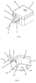
- FIG 2 is a perspective view of the mobile manipulator 1 of figure 1 in which an under-surface 20 of the mobile manipulator 1 is shown.
- Said mobile manipulator 1 comprises a piezoelectric actuator 23 which are operable to manoeuvre the mobile manipulator 1.
- the piezoelectric actuator 23 comprises a piezoelectric ceramic plate 20 and a plurality of ruby contacts 21, which are fixed to said piezoelectric ceramic plate 20.
- the piezoelectric actuator 23 can operate to manoeuvre the mobile manipulator 1 using a stick and slip principle: a stick and slip principle comprises a first, stick, phase and a second, slip, phase; during the first, stick, phase, the piezoelectric ceramic plate 20 is compressed by applying an electrical field across the ceramic plate 20.
- the ruby contacts 21 grip the surface on which the mobile manipulator 1 rests, so that mobile manipulator 1 is dragged forward.
- the electrical field is removed from the piezoelectric ceramic plate 20 or the direction of the electric field is reversed; the piezoelectric ceramic plate 20 returns quickly from its compressed state to its uncompressed state; due to high inertia of said mobile manipulator 1, the ruby contacts 21 will slide over the surface on which the mobile manipulator 1 rests without moving the mobile manipulator 1.
- the piezoelectric ceramic plate 20 first, stick, phase may be repeated.
- the stick and slip phases are repeated to move the mobile manipulator 1 further forward.
- the piezoelectric actuator 23 can move the mobile manipulator 1 in any orientation, including linearly or rotationally.
- the piezoelectric actuator 23 enables movement resolution one tenth of a nanometer and displacements up to several centimetres, to be achieved.
- the mobile manipulator 1 further comprises a magnet 22. If the surface on which the mobile manipulator 1 rests is a ferromagnetic surface, then the magnet 22 may be used to secure the mobile manipulator 1 to the surface. The magnetic force between the magnet 22 and surface, will pull the mobile manipulator 1 towards the surface thus increasing the frictional forces which exist between the ruby contacts 21 and the surface.
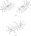
- Figure 3 is a perspective view of the first and second parts which define the tool holder assembly 3.
- Figure 4 shows a perspective view of the first and second parts of the tool holder assembly shown in Figure 3 , when assembled.
- the tool holder assembly 3 comprises, a first part 30 which is configured such that it is attachable to a mobile vehicle; and a second part 31.
- a tool 6 may be connected to the second part 31 by means of a support 5 for example. It should be understood that the tool 6 and support 5 are not essential features of the tool holder assembly 3.
- the first part 30 and second part 31 each comprise conductive material, non-magnetic material and/or plastic.
- the first and second parts 30,31 each comprise, a first flexible arm 8,10 and a second flexible arm 9,11.
- Each of the first and second flexible arms 8,9,10,11 in each of the first and second parts 30,31, comprise a projection 16, 17, 18, 19.
- Each projection comprises a curved surface 33.
- the first and second parts 30,31 each comprise a slot 14,15 which is defined by a through-hole in each of the respective first and second parts 30,31 so that each slot 14,15 is accessible from opposite sides of each part.
- the projections 16,17 on the first and second flexible arms 8,9 on the first part 30 are dimensioned such that at least a portion of each projection 16,17 may be received into the slot 15 on the second part 31.
- the projections 18, 19 on the first and second flexible arms 10,11 on the second part 31 are dimensioned such that at least a portion of each projection 18,19 may be received into the slot 14 on the first part 30.
- the curved surfaces 33 on the projections 16,17,18,19 will facilitate the projections 16,17,18,19 in being received into their respective slots 14,15.
- the dimensions of the first and second parts 30,31 are such that they can be arranged so that the projections 16,17,18,19 on each of the first and second flexible arms 8,9,10,11 of each of the first and second parts 30,31, may be simultaneously received into the slot 14,15 of the other part 30,31.
- the projections 16,17 on the first and second flexible arms 8,9 of the first part 30 are received into the slot 15 in the second part 31.
- the slot 15 on the second part 31 is defined by a through-hole the projection 17 on the first flexible arm 8 is inserted into a slot 15 opening located on a first side 34 of the second part 31, and the projection 16 on the second flexible arm 9 is inserted into a slot 15 opening located on a second side 36 of the second part 31.
- the projections 18,19 on the first and second flexible arms 10,11 of the second part 31 are received into the slot 14 in the first part 30.
- the slot 14 on the first part is defined by a through-hole
- the projection 19 on the first flexible arm 10 is inserted into a slot 14 opening located on a first side 37 of the first part 30, and the projection 18 on the second flexible arm 11 is inserted into a slot 14 opening located on the a second side 38 of the first part 30.
- the projections 16,17,18,19 on each of the first and second flexible arms 8,9,10,11, of each of the first and second parts 30,31 are simultaneously received into the slot 14,15 of the other part 30,31.
- the dimensions of the slots 14,15 and projections 16,17,18,19 are such that when the first and second parts 30,31 are arranged to cooperate such that all the projections 16,17,18,19 are received into their respective slots 14,15, each of the first and second flexible arms 8,9,10,11, of each of the first and second parts 30,31, will be flexed.
- the elastic force of the flexible arms 8,9,10,11 will maintain the projections 16,17,18,19 inserted in their respective slots 14,15; as a result the first and second parts are maintained in mechanical cooperation. Additionally, the elastic force of the flexible arms 8,9,10,11 will ensure that the flexible arms 8,9 of the first part 30, will grip the second part 31, and that the flexible arms 10,11 of the second part, will grip the first part 30.
- the dimensions of the opening of each slot 14,15, the dimensions of the projections 16,17,18,19 on the first and second flexible arms 8,9,10,11 of each part 30,31, and the elasticity of the first and second flexible arms 8,9,10,11, are such that the first and second parts 30,31 are held in rigid mechanical cooperation so that the first and second parts 30,31 are prevented from moving with respect to one another.
- each slot 14,15 each have the dimensions 0.5mm x 1 mm x 1 mm; the dimensions of the first and second flexible arms 8,9,10,11 of each part 30,31 are 5.1 mm x 0.4mm x 1 mm; and the spring constant of the first and second flexible arms 8,9,10,11 of each of the first and second parts 30,31 is between 0.5 and 10N/mm 2 .
- each of the first and second parts 30,31 further comprise a stopper 12, 13 in the form of an extension 12,13 which is interposed between the first and second flexible arms 8,9,10,11.
- the extension 12,13 on each of the first and second parts 30,31 are configured to restrict the relative movement between first and second parts 30,31 as the first part and second parts are being arranged to mechanically cooperate (as shown in figure 4 ).
- Each extension has a length 'L' which ensures that, when the first and second parts 30,31 are being arranged such that the projections 16,17,18,19 on each of the first and second flexible arms 8,9,10,11 of the each of the first and second parts 30,31 are simultaneously received into the slot 14,15 of the other part 30,31, an end 42 of the extension 12 on the first part 30 will abut an end 43 of the extension 13 on the second part 31. As the extensions 12,13 abut they will prevent the first and second parts 30,31 from moving so that the projections 16,17,18,19 are moved beyond the slots 14,15 on the other part 30,31.
- first and second flexible arms 8,9,10,11 of each of the first and second parts 30,31 define a receiving region 44,45 which can receive the extension 12,13 provided on the other part 30,31. Accordingly, when the first and second parts 30,31 are arranged in mechanical cooperation, as shown in figure 4 , the extension 12 provided on the first part 30 is received into the receiving region 45 in the second part 31 and the extension 13 provided on the second part 31 is received into the receiving region 44 in the first part 30.
- the first part 30 may further comprise a connecting means (not shown) which is suitable for connecting to a second connecting means (not shown) provided on the mobile vehicle; the connecting means will facilitate easy connection of the first part 30 to the mobile vehicle 50.
- a connecting means (not shown) which is suitable for connecting to a second connecting means (not shown) provided on the mobile vehicle; the connecting means will facilitate easy connection of the first part 30 to the mobile vehicle 50.
- the first part 30 of the tool holder assembly 3 is glued to the mobile vehicle 50. It will be understood that the first part 30 of the tool holder assembly may alternatively be fixed to the mobile vehicle 50 using screws, clips, welding, soldering.
- the second part 31 may further comprise a connecting means which is suitable for releasably connecting to a tool 6.
- a tool 6 will be fixed to the second part 31, or integral to the second part 31.
- the tool 6 will fixed to the second part 31 during manufacturing process, so that a user is not required to handle the tool 6 independently of the second part 31.
- the tool holder assembly 3 of the present invention allows a user easily mount or replace tools 6 on a mobile vehicle 50 (e.g. to mount or replace tools on a mobile platform of a mobile manipulator).
- a tool 6 may be pre-attached to the second part 31 of the tool assembly 3 during the manufacturing stage; typically a user will comprise a plurality of second parts 31 each having a different tool 6 attached thereto.
- the first part 30 may be pre-attached to the mobile vehicle 50.
- a user will select a suitable tool 6 to be mounted on the mobile vehicle 50; thus providing a mobile manipulator 1 which is suitable for the application.
- the user is required to simply arrange the second part 31, to which the tool 6 is attached, so that the projections 19,18 of the first and second flexible arms 10,11 of the second part 31 are received into the slot 14 on the first part 30 and such that the projections 16, 17 of the first and second flexible arms 8,9 of the first part 30 are received into the slot 15 on the second part 31. Then, the projections 16,17,18,19 which are inserted into the slots 14,15, the elastic force of the flexible arms 8,9,10,11 and the extensions 12,13 will ensure that the first and second parts 30,31 are prevented from moving with respect to one another; accordingly the first and second parts 30,31 will be rigidly connected. A user can thus easily configure a mobile manipulator 1 so that it is suitable for a particular application.
- the user is required simply to remove the projections 16,17,18,19 of the first and second flexible arms 8,9,10,11 from their respective slots 14,15 so that the second part 31 is no longer held in mechanical cooperation with the first part 30; the second part 31 and tool 6 (which is attached to the second part 31) can thus be removed from the mobile manipulator 1.
- the user may then apply another second part 31, which has the desired tool 6 pre-attached thereto, to the first part 30, which is attached to the mobile vehicle 50.
- a user may easily reconfigure the mobile manipulator 1 so that it is suitable for a different application.
- the present invention enables a user to quickly, and easily replace and mount tools 6 on a mobile manipulator 1 and obviates the need for either fixed attachments in which tools 6 cannot be replaced, or screw attachments which require high dexterity.
- the tool 6 is preferably fixed, or pre-attached to the second part 31 during the manufacturing process, a user is not required to handle a small dimensioned tool 6 alone; the user is required to handle the second part 31 to which the tool 6 is fixed, or pre-attached. Since the second part 31 with the tool 6 attached will have larger dimensions than the tool 6 alone, this makes for easier handling, application, and replacement of tools 6 on the mobile manipulator 1.
- the first part 30 and second part 31 of the tool assembly 3 will have dimensions in the range from 2.5mm x 0.5mm x 0.3mm up to 40mm x 10mm x 5mm (length x width x height), and preferably will have dimensions 8mm x 2mm x 1 mm (length x width x height).
- the first part 30 of the tool handling assembly 3 is pre-attached, or fixed, to an movable actuator or fixed part of the mobile vehicle 50.
- the first part 30 may be attached using glue or any other suitable securing means such as screws, clamps, welding, or soldering.
- a plurality of second parts 31 are provided, each having a different tool 6 pre-attached thereto. A user selects a second part 31 which has a desired tool attached thereto.
- the extension 12 on the first part 30 and the extension 13 on the second part 31 will abut one another to prevent further movement of the second part 31, relative to the first part 30.
- the projections 18,19 on the first and second flexible arms 10,11 of the second part 31 will clip into the slot 14 on the first part 30 and the projections 16,17 on the first and second flexible arms 8,9 of the first part 30 will clip into the slot 15 on the second part 31.
- the curved surface 33 of the projections 16,17,18,19 will facilitate the insertion of the projections 16,17,18,19 into their respective slots 14,15.
- the first and second flexible arms 8,9,10,11 of each part 30,31 will be in a flexed position and the elastic force of the first and second flexible arms 8,9,10,11 will maintain the projections inserted in their respective slots.
- the elastic force of the first and second flexible arms 8,9,10,11 of each of the first and second parts 30,31 will also ensure that the first and second parts 30,31 frictionally grip one another.
- the projections 16,17,18,19, slots 14,15, elastic force of the flexible arms 8,9,10,11, and the extensions 12,13, will prevent the first and second parts 30,31 from moving with respect to each other; and the first and second parts will be maintained in rigid mechanical cooperation.
- the dimension of the opening of each slot 14,15, the location of the slots (specifically, its location relative to said extension 12,13) as well as the distance between the projections 16,17,18,19 on the first and second flexible arms 8,9,10,11, may be such that the projections 16,17,18,19 on each flexible arm 8,9,10,11 are not fully received into their respective slots 14,15 when the first and second parts are arranged in mechanical cooperation; this will result in an increase in the amount that the first and second flexible arms 8,9,10,11 of each part 30,31 are flexed and thus will increase the elastic force which is applied by the flexed first and second flexible arms 8,9,10,11. This will further increase the amount which the flexible arms 8,9,10,11 of one part 30,31 frictionally grip the other part 30,31.
- an electrical cable may be used to connect the tool handling assembly 3 to the electrical connector 2 on the mobile vehicle 50.
- the shape of the first and second parts allows simple and low cost manufacturing; both the first and second parts of the attachment system can be easily cut out from a plate using, for example, a laser cutter.
- the force required to arrange the first and second parts 30,31 in mechanical cooperation and the elastic force of the flexed flexible arms 8,9,10,11 may depend on the thickness, height and length of the first and second flexible arms 8,9,10,11.
- the dimensions of the first and second flexible arms 8,9,10,11 of each part 30,31 may range from 1.5mm x 0.1 mm x 0.3mm up to 25mm x 2mm x 5mm (length x thickness x height).
- the dimensions of the first and second flexible arms 8,9,10,11 of each part 30,31 will be 5.1 mm x 0.4mm x 1 mm (length x thickness x height).
- the first and second parts 30,31 will be configured such that the force required to arrange the first and second parts 30,31 in mechanical cooperation is preferably within the range of 0.1 N up to 5N.
- the first and second parts 30,31 will be configured such that the force required to arrange the first and second parts 30,31 in mechanical cooperation is 2N. This reduces the possibility of damage being caused to a tool 6 attached to the second part 31, or to either of the first and second parts 30,31.
- the force required to arrange the first and second parts 30,31 in mechanical cooperation is dictated by the dimensions of the first and second parts 30,31, the dimensions of the first and second flexible arms 8,9,10,11 of each part 30,31, and the elasticity of the first and second flexible arms 8,9,10,11.
- the flexible cable 7 could alternatively be rigid if said first part 30 of the tool holder assembly 3 is rigidly attached to said mobile vehicle 50, or flexible if said first part 30 of the tool holder assembly 3 is actuated and mobile.
- the rigid or flexible cable 7 may comprise one or a plurality of electrical conductors, so that the flexible cable could be used to transmit one or several electrical signals.
Landscapes
- Engineering & Computer Science (AREA)
- Robotics (AREA)
- Mechanical Engineering (AREA)
- Manipulator (AREA)
Claims (15)
- Eine Werkzeughalteranordnung (3) ausgebildet zur Benutzung in einem mobilen Manipulator (1), die Werkzeughalteranordnung (3) aufweisend,
ein erstes Teil (30), das so ausgebildet ist, dass es an einem mobilen Gefährt (50) befestigbar ist; und
ein zweites Teil (31), das ausgebildet ist, mit einem Werkzeug (6) zusammenzuarbeiten;
wobei das erste und das zweite Teil (30, 31) jeweils einen ersten flexiblen Arm (8, 10) und einen zweiten flexiblen Arm (9, 11) und einen Einschub (14, 15) aufweist;
dadurch gekennzeichnet, dass das erste und das zweite Teil (30, 31) so ausgebildet sind, dass sie so angeordnet werden können, dass mindestens ein Teil (16, 17, 18, 19) des ersten und zweiten flexiblen Arms (8, 9, 10, 11) jedes des ersten und zweiten Teils (30, 31) gleichzeitig in einem oder mehreren Einschüben (14, 15) in dem anderen Teil (39, 31) empfangen werden kann, um das erste und das zweite Teil (30, 31) in mechanischem Zusammenspiel zu halten. - Werkzeughalteranordnung (3) nach Anspruch 1, wobei die Teile (16, 17, 18, 19) des ersten und zweiten flexiblen Arms (8, 9, 10, 11) jedes des ersten und zweiten Teils (30, 31) an dem ersten und zweiten flexiblen Arm angebrachte Vorsprünge sind.
- Werkzeughalteranordnung (3) nach Anspruch 2, wobei das erste und das zweite Teil (30, 31) so ausgebildet sind, dass, wenn die Vorsprünge (16, 17, 18, 19) auf dem ersten und dem zweiten flexiblen Arm (8, 9, 10, 11) jedes Teils in dem Einschub (14, 15) des anderen Teils empfangen werden, der erste und der zweite flexible Arm (8, 9, 10, 11) jedes Teils (30, 31) gebogen ist, so dass der erste und zweite flexible Arm (8, 9, 10, 11) eines Teil eine elastische Kraft auf das andere Teil ausübt.
- Werkzeughalteranordnung (3) nach Anspruch 3, wobei die Dimensionen des Einschubs (14, 15) kleiner als die Dimensionen der Vorsprünge (16, 17, 18, 19) auf dem ersten und zweiten flexiblen Arm (8, 9, 10, 11) ist, so dass nur ein Teil jedes Vorsprungs (16, 17, 18, 19) in jedem Einschub (14, 15) empfangen wird, so dass der erste und zweite flexible Arm (8, 9, 10, 11) gebogen werden, wenn die Vorsprünge (16, 17, 18, 19) auf dem ersten und zweiten flexiblen Arm (8, 9, 10, 11) jedes Teils in dem Einschub (14, 15) des anderen Teils empfangen werden, so dass der erste und zweite flexible Arm (8, 9) des ersten Teils (30) eine elastische Kraft auf das zweite Teil (31) ausübt und der erste und zweite flexible Arm (10, 11) zweiten Teils (31) eine elastische Kraft auf das erste Teil (30) ausübt.
- Werkzeughalteranordnung (3) nach einem der vorigen Ansprüche, wobei der Einschub (14, 15) in jedem des ersten und zweiten Teils (30, 31) durch ein in dem ersten und zweiten Teil (30, 31) bereitgestellten Durchgangsloch definiert ist.
- Werkzeughalteranordnung (3) nach einem der vorigen Ansprüche, wobei jedes des ersten und zweiten Teils (30, 31) weiter einen Stopper aufweist, der ausgebildet ist die relative Bewegung zwischen dem ersten Teil und dem zweiten Teil (30, 31), wenn das erste und zweite Teil angeordnet sind, um zu zusammenzuarbeiten.
- Werkzeughalteranordnung (3) nach Anspruch 6, wobei jeder Stopper eine Erweiterung (12, 13) aufweist, die zwischen dem ersten und dem zweiten flexiblen Arm (8, 9, 10, 11) angeordnet ist, wobei jede Erweiterung (12, 13) so ausgebildet ist, dass die Erweiterung auf dem ersten Teil (12) an die Erweiterung auf dem zweiten Teil (13) stösst, wenn der Teil (16, 17, 18, 19) des ersten und zweiten flexiblen Arms (8 9, 10, 11) jedes des ersten und zweiten Teils (30, 31) gleichzeitig in dem einen oder mehreren Einschüben (14, 15) des anderen Teils empfangen wird.
- Werkzeughalteranordnung (3) nach einem der vorigen Ansprüche, wobei das erste Teil (30) ein Verbindungsmittel zum Verbinden der Werkzeughalteranordnung mit einem mobilen Gefährt.
- Werkzeughalteranordnung (3) nach einem der vorigen Ansprüche, wobei das zweite Teil (31) weiter ein Werkzeug (6) aufweist, das daran befestigt ist.
- Werkzeughalteranordnung (3) nach Anspruch 9, wobei das Werkzeug mindestens eine aus einem Kraftsensor, einem thermischen/Hitzesensor, eine elektrische Probenspitze, eine atomare Kraftmikroskopprobenspitze, einen micro/nano Greifer, eine mikro/nano Pinzette, eine optische Faser, eine Pipette, eine Antenne, Elektroden, ein Mikroventil, einen Flüssigkeits-/Gaseinführer, einen Flüssigkeitsspender, eine Tunnelmikroskopspitze, ein Saug..., ein Reinigungssystem, ein Kratzsystem, ein Schweisssystem, ein Schraubenzieher, ein Scangerät, ein Aktuator, ein Aktuatorsubsystem mit mindestens einem Freiheitsgrad, und/oder einem Sensor, der für das Messen physikalischer Parameter ausgebildet ist, aufweist.
- Werkzeughalteranordnung (3) nach einem der vorigen Ansprüche, wobei die Werkzeughalteranordnung (3) weiter eine elektrische Schnittstelle aufweist, die die Werkzeughalteranordnung (3) mit einem mobilen Gefährt (50) elektrisch verbinden kann.
- Werkzeughalteranordnung (3) nach einem der Ansprüche 2 bis 12, wobei jede der Vorsprünge (16, 17, 18, 19) eine gekrümmte Oberfläche (33) aufweist.
- Mobiler Manipulator aufweisend ein mobiles Gefährt (50) und eine Werkzeughalteranordnung (3) nach einem der Ansprüche 1 bis 12, die an dem mobilen Gefährt (50) angeordnet ist.
- Werkzeughalteranordnungskit aufweisend,
ein erstes Teil (30) einer Werkzeughalteranordnung (3), das so ausgebildet ist, dass es an einem mobilen Gefährt (1) befestigbar ist; und
zwei oder mehrere zweite Teile (31) der Werkzeughalteranordnung (3), wobei jedes der zwei oder mehr zweiten Teile (31) ein daran befestigtes unterschiedliches Werkzeug (6) aufweisen;
wobei das erste Teil (30) und die zwei oder mehr zweite Teile (31) jeweils einen ersten flexiblen Arm (8, 10) und einen zweiten flexiblen Arm (9, 11) und einen Einschub (14, 15) aufweist;
dadurch gekennzeichnet, dass das erste und das zweite Teil (30, 31) so ausgebildet sind, dass das erste Teil (30) und jedes der zweiten Teile (31) so angeordnet werden können, dass mindestens ein Teil (16, 17, 18, 19) jedes des ersten und zweiten flexiblen Arms (8, 9, 10, 11) jedes des ersten und zweiten Teils (30, 31) gleichzeitig in den Einschüben (14, 15) des anderen Teils (39, 31) empfangen werden kann, um das erste und das zweite Teil (30, 31) in mechanischem Zusammenspiel zu halten. - Werkzeughalteranordnungskit nach Anspruch 14, wobei die Teile des ersten und zweiten flexiblen Arms (8, 9, 10, 11) jedes des ersten und zweiten Teils (30, 31) an dem ersten und zweiten flexiblen Arm angebrachte Vorsprünge sind, und wobei die Ausdehnungen des Einschubs (14, 15) kleiner als die Ausdehnungen der Vorsprünge (16, 17, 18, 19) sind, so dass nur ein Teil jedes Vorsprungs (16, 17, 18, 19) in jedem Einschub (14, 15) empfangen wird, so dass der erste und zweite flexible Arm (8, 9, 10, 11) gebogen werden, wenn die Vorsprünge (16, 17, 18, 19) auf dem ersten und zweiten flexiblen Arm (8, 9, 10, 11) jedes Teils in dem Einschub (14, 15) des anderen Teils empfangen werden.
Applications Claiming Priority (2)
| Application Number | Priority Date | Filing Date | Title |
|---|---|---|---|
| CH1372012 | 2012-02-01 | ||
| PCT/EP2013/050755 WO2013113557A1 (en) | 2012-02-01 | 2013-01-16 | Electromechanical tool holder assembly for mobile manipulation apparatus |
Publications (2)
| Publication Number | Publication Date |
|---|---|
| EP2809486A1 EP2809486A1 (de) | 2014-12-10 |
| EP2809486B1 true EP2809486B1 (de) | 2016-04-06 |
Family
ID=47605499
Family Applications (1)
| Application Number | Title | Priority Date | Filing Date |
|---|---|---|---|
| EP13701405.6A Active EP2809486B1 (de) | 2012-02-01 | 2013-01-16 | Elektromechanisches werkzeug halteranordnung für eine fahrbarer handhabungsvorrichtung |
Country Status (3)
| Country | Link |
|---|---|
| US (1) | US9925671B2 (de) |
| EP (1) | EP2809486B1 (de) |
| WO (1) | WO2013113557A1 (de) |
Families Citing this family (2)
| Publication number | Priority date | Publication date | Assignee | Title |
|---|---|---|---|---|
| CN114778422B (zh) * | 2022-04-19 | 2023-09-08 | 北京理工大学 | 一种基于微液滴操控技术的自动化细胞分选系统及其方法 |
| CN115971083B (zh) * | 2022-12-02 | 2025-09-26 | 宁波佳韵电子有限公司 | 一种电路板检测设备 |
Family Cites Families (16)
| Publication number | Priority date | Publication date | Assignee | Title |
|---|---|---|---|---|
| US3350752A (en) * | 1966-08-02 | 1967-11-07 | Walter A Plummer | Laterally-engaging self-locking plastic seam assembly |
| US3413752A (en) * | 1967-11-14 | 1968-12-03 | Charles O. Perry | Body having a snap-type fastener |
| FR2639573A1 (fr) * | 1988-11-30 | 1990-06-01 | Snecma | Support souple dispose entre un porte-outil et un bras mobile de robot |
| US5640744A (en) * | 1990-07-16 | 1997-06-24 | Allan; Robert M. | Nested ridge strap connector apparatus |
| US5791810A (en) * | 1995-09-21 | 1998-08-11 | Williams; Douglas | Connecting apparatus |
| US5774955A (en) * | 1996-06-28 | 1998-07-07 | First Brands Corporation | Closure device providing tactile confirmation of occlusion |
| US6367128B1 (en) * | 2000-02-10 | 2002-04-09 | 3M Innovative Properties Company | Self-mating reclosable mechanical fastener |
| US6854886B2 (en) * | 2002-06-28 | 2005-02-15 | Illinois Tool Works Inc. | Watertight closure for a reclosable package |
| US20080182738A1 (en) * | 2007-01-31 | 2008-07-31 | Terry Grunke | Robotic end-of-arm tool quick-change device |
| US8011849B2 (en) * | 2008-04-24 | 2011-09-06 | Douglas Williams | Corner connector |
| US8776376B2 (en) * | 2008-04-24 | 2014-07-15 | Douglas Williams | Method of forming paneled corners |
| US20100009825A1 (en) * | 2008-07-10 | 2010-01-14 | Ati Industrial Automation, Inc. | Compliant Service Transfer Module for Robotic Tool Changer |
| US8857821B2 (en) * | 2008-09-05 | 2014-10-14 | Ati Industrial Automation, Inc. | Manual robotic tool changer with rotating piston |
| US8533930B2 (en) * | 2008-09-05 | 2013-09-17 | Ati Industrial Automation, Inc. | Manual robotic tool changer having rapid coupling mechanism |
| US9724830B2 (en) * | 2008-09-05 | 2017-08-08 | Ati Industrial Automation, Inc. | Manual robotic tool changer with rolling members |
| US8079186B2 (en) * | 2008-12-22 | 2011-12-20 | Douglas Williams | Soffit system |
-
2013
- 2013-01-16 EP EP13701405.6A patent/EP2809486B1/de active Active
- 2013-01-16 US US14/372,962 patent/US9925671B2/en active Active
- 2013-01-16 WO PCT/EP2013/050755 patent/WO2013113557A1/en not_active Ceased
Non-Patent Citations (1)
| Title |
|---|
| None * |
Also Published As
| Publication number | Publication date |
|---|---|
| US9925671B2 (en) | 2018-03-27 |
| EP2809486A1 (de) | 2014-12-10 |
| WO2013113557A1 (en) | 2013-08-08 |
| US20150015010A1 (en) | 2015-01-15 |
Similar Documents
| Publication | Publication Date | Title |
|---|---|---|
| CN104603515B (zh) | 固持装置 | |
| US20110304241A1 (en) | Apparatus and method for electromechanical positioning | |
| CN108656105B (zh) | 自动取料设备 | |
| US8752283B2 (en) | Assembly of electronic and optical devices | |
| EP2809486B1 (de) | Elektromechanisches werkzeug halteranordnung für eine fahrbarer handhabungsvorrichtung | |
| KR101081634B1 (ko) | 초소형 커넥터 및 커넥터가 장치되는 무동력 초소형 조립체 | |
| JP7203127B2 (ja) | エネルギ処置具及び処置システム | |
| JP3232783U (ja) | クランプホルダ | |
| CN111133319A (zh) | 用于操作测量探针的操作设备 | |
| JP2020019104A (ja) | グリッパーモジュール及びグリッパー装置 | |
| JP4373449B2 (ja) | 超音波モータを備えた微動機構及び振動体保持機構 | |
| US20140159545A1 (en) | Piezoelectric linear actuator | |
| US11101749B2 (en) | Vibration wave motor and imaging device having vibration wave motor | |
| CN110896018B (zh) | 具备双机械手的扫描电子显微镜样品台 | |
| CN111108651A (zh) | 用于连接电线的连接装置 | |
| US20150349665A1 (en) | Piezoelectric actuator and robot | |
| KR102903993B1 (ko) | 마이크로 액추에이터용 장치 및 이러한 장치가 장착된 마이크로 액추에이터 | |
| JP4087054B2 (ja) | 電子顕微鏡 | |
| RU2297078C1 (ru) | Позиционер трехкоординатный | |
| JP7804976B2 (ja) | 駆動装置 | |
| US20140284950A1 (en) | Micro-nano tools with changeable tips for micro-nano manipulation | |
| JP3856171B2 (ja) | 標本ホルダ付き顕微鏡ステージ | |
| KR101672263B1 (ko) | 전자현미경용 홀더장치 및 이에 적용되는 탐침 유니트 | |
| JP2021157938A (ja) | コネクタ位置決め装置 | |
| JP2025009942A (ja) | クランプ装置およびセンサケーブル |
Legal Events
| Date | Code | Title | Description |
|---|---|---|---|
| PUAI | Public reference made under article 153(3) epc to a published international application that has entered the european phase |
Free format text: ORIGINAL CODE: 0009012 |
|
| 17P | Request for examination filed |
Effective date: 20140716 |
|
| AK | Designated contracting states |
Kind code of ref document: A1 Designated state(s): AL AT BE BG CH CY CZ DE DK EE ES FI FR GB GR HR HU IE IS IT LI LT LU LV MC MK MT NL NO PL PT RO RS SE SI SK SM TR |
|
| AX | Request for extension of the european patent |
Extension state: BA ME |
|
| DAX | Request for extension of the european patent (deleted) | ||
| GRAP | Despatch of communication of intention to grant a patent |
Free format text: ORIGINAL CODE: EPIDOSNIGR1 |
|
| INTG | Intention to grant announced |
Effective date: 20150715 |
|
| GRAS | Grant fee paid |
Free format text: ORIGINAL CODE: EPIDOSNIGR3 |
|
| INTG | Intention to grant announced |
Effective date: 20160202 |
|
| GRAA | (expected) grant |
Free format text: ORIGINAL CODE: 0009210 |
|
| AK | Designated contracting states |
Kind code of ref document: B1 Designated state(s): AL AT BE BG CH CY CZ DE DK EE ES FI FR GB GR HR HU IE IS IT LI LT LU LV MC MK MT NL NO PL PT RO RS SE SI SK SM TR |
|
| REG | Reference to a national code |
Ref country code: GB Ref legal event code: FG4D |
|
| REG | Reference to a national code |
Ref country code: AT Ref legal event code: REF Ref document number: 787234 Country of ref document: AT Kind code of ref document: T Effective date: 20160415 Ref country code: CH Ref legal event code: EP Ref country code: CH Ref legal event code: NV Representative=s name: P&TS SA, CH |
|
| REG | Reference to a national code |
Ref country code: DE Ref legal event code: R082 Ref document number: 602013006190 Country of ref document: DE Representative=s name: BECK & ROESSIG - EUROPEAN PATENT ATTORNEYS, DE Ref country code: DE Ref legal event code: R082 Ref document number: 602013006190 Country of ref document: DE Representative=s name: WOHLMUTH, JOHANNES, DE Ref country code: DE Ref legal event code: R082 Ref document number: 602013006190 Country of ref document: DE Representative=s name: WOHLMUTH, JOHANNES, DIPL.-PHYS., DE |
|
| REG | Reference to a national code |
Ref country code: IE Ref legal event code: FG4D |
|
| REG | Reference to a national code |
Ref country code: DE Ref legal event code: R096 Ref document number: 602013006190 Country of ref document: DE |
|
| REG | Reference to a national code |
Ref country code: NL Ref legal event code: FP |
|
| REG | Reference to a national code |
Ref country code: LT Ref legal event code: MG4D |
|
| REG | Reference to a national code |
Ref country code: AT Ref legal event code: MK05 Ref document number: 787234 Country of ref document: AT Kind code of ref document: T Effective date: 20160406 |
|
| PG25 | Lapsed in a contracting state [announced via postgrant information from national office to epo] |
Ref country code: FI Free format text: LAPSE BECAUSE OF FAILURE TO SUBMIT A TRANSLATION OF THE DESCRIPTION OR TO PAY THE FEE WITHIN THE PRESCRIBED TIME-LIMIT Effective date: 20160406 Ref country code: PL Free format text: LAPSE BECAUSE OF FAILURE TO SUBMIT A TRANSLATION OF THE DESCRIPTION OR TO PAY THE FEE WITHIN THE PRESCRIBED TIME-LIMIT Effective date: 20160406 Ref country code: LT Free format text: LAPSE BECAUSE OF FAILURE TO SUBMIT A TRANSLATION OF THE DESCRIPTION OR TO PAY THE FEE WITHIN THE PRESCRIBED TIME-LIMIT Effective date: 20160406 Ref country code: IS Free format text: LAPSE BECAUSE OF FAILURE TO SUBMIT A TRANSLATION OF THE DESCRIPTION OR TO PAY THE FEE WITHIN THE PRESCRIBED TIME-LIMIT Effective date: 20160806 Ref country code: NO Free format text: LAPSE BECAUSE OF FAILURE TO SUBMIT A TRANSLATION OF THE DESCRIPTION OR TO PAY THE FEE WITHIN THE PRESCRIBED TIME-LIMIT Effective date: 20160706 |
|
| PG25 | Lapsed in a contracting state [announced via postgrant information from national office to epo] |
Ref country code: GR Free format text: LAPSE BECAUSE OF FAILURE TO SUBMIT A TRANSLATION OF THE DESCRIPTION OR TO PAY THE FEE WITHIN THE PRESCRIBED TIME-LIMIT Effective date: 20160707 Ref country code: HR Free format text: LAPSE BECAUSE OF FAILURE TO SUBMIT A TRANSLATION OF THE DESCRIPTION OR TO PAY THE FEE WITHIN THE PRESCRIBED TIME-LIMIT Effective date: 20160406 Ref country code: PT Free format text: LAPSE BECAUSE OF FAILURE TO SUBMIT A TRANSLATION OF THE DESCRIPTION OR TO PAY THE FEE WITHIN THE PRESCRIBED TIME-LIMIT Effective date: 20160808 Ref country code: AT Free format text: LAPSE BECAUSE OF FAILURE TO SUBMIT A TRANSLATION OF THE DESCRIPTION OR TO PAY THE FEE WITHIN THE PRESCRIBED TIME-LIMIT Effective date: 20160406 Ref country code: RS Free format text: LAPSE BECAUSE OF FAILURE TO SUBMIT A TRANSLATION OF THE DESCRIPTION OR TO PAY THE FEE WITHIN THE PRESCRIBED TIME-LIMIT Effective date: 20160406 Ref country code: LV Free format text: LAPSE BECAUSE OF FAILURE TO SUBMIT A TRANSLATION OF THE DESCRIPTION OR TO PAY THE FEE WITHIN THE PRESCRIBED TIME-LIMIT Effective date: 20160406 Ref country code: SE Free format text: LAPSE BECAUSE OF FAILURE TO SUBMIT A TRANSLATION OF THE DESCRIPTION OR TO PAY THE FEE WITHIN THE PRESCRIBED TIME-LIMIT Effective date: 20160406 Ref country code: ES Free format text: LAPSE BECAUSE OF FAILURE TO SUBMIT A TRANSLATION OF THE DESCRIPTION OR TO PAY THE FEE WITHIN THE PRESCRIBED TIME-LIMIT Effective date: 20160406 |
|
| PG25 | Lapsed in a contracting state [announced via postgrant information from national office to epo] |
Ref country code: BE Free format text: LAPSE BECAUSE OF FAILURE TO SUBMIT A TRANSLATION OF THE DESCRIPTION OR TO PAY THE FEE WITHIN THE PRESCRIBED TIME-LIMIT Effective date: 20160406 Ref country code: IT Free format text: LAPSE BECAUSE OF FAILURE TO SUBMIT A TRANSLATION OF THE DESCRIPTION OR TO PAY THE FEE WITHIN THE PRESCRIBED TIME-LIMIT Effective date: 20160406 |
|
| REG | Reference to a national code |
Ref country code: DE Ref legal event code: R097 Ref document number: 602013006190 Country of ref document: DE |
|
| REG | Reference to a national code |
Ref country code: FR Ref legal event code: PLFP Year of fee payment: 5 |
|
| PG25 | Lapsed in a contracting state [announced via postgrant information from national office to epo] |
Ref country code: SK Free format text: LAPSE BECAUSE OF FAILURE TO SUBMIT A TRANSLATION OF THE DESCRIPTION OR TO PAY THE FEE WITHIN THE PRESCRIBED TIME-LIMIT Effective date: 20160406 Ref country code: CZ Free format text: LAPSE BECAUSE OF FAILURE TO SUBMIT A TRANSLATION OF THE DESCRIPTION OR TO PAY THE FEE WITHIN THE PRESCRIBED TIME-LIMIT Effective date: 20160406 Ref country code: EE Free format text: LAPSE BECAUSE OF FAILURE TO SUBMIT A TRANSLATION OF THE DESCRIPTION OR TO PAY THE FEE WITHIN THE PRESCRIBED TIME-LIMIT Effective date: 20160406 Ref country code: DK Free format text: LAPSE BECAUSE OF FAILURE TO SUBMIT A TRANSLATION OF THE DESCRIPTION OR TO PAY THE FEE WITHIN THE PRESCRIBED TIME-LIMIT Effective date: 20160406 Ref country code: RO Free format text: LAPSE BECAUSE OF FAILURE TO SUBMIT A TRANSLATION OF THE DESCRIPTION OR TO PAY THE FEE WITHIN THE PRESCRIBED TIME-LIMIT Effective date: 20160406 |
|
| PLBE | No opposition filed within time limit |
Free format text: ORIGINAL CODE: 0009261 |
|
| STAA | Information on the status of an ep patent application or granted ep patent |
Free format text: STATUS: NO OPPOSITION FILED WITHIN TIME LIMIT |
|
| PG25 | Lapsed in a contracting state [announced via postgrant information from national office to epo] |
Ref country code: SM Free format text: LAPSE BECAUSE OF FAILURE TO SUBMIT A TRANSLATION OF THE DESCRIPTION OR TO PAY THE FEE WITHIN THE PRESCRIBED TIME-LIMIT Effective date: 20160406 |
|
| 26N | No opposition filed |
Effective date: 20170110 |
|
| PG25 | Lapsed in a contracting state [announced via postgrant information from national office to epo] |
Ref country code: SI Free format text: LAPSE BECAUSE OF FAILURE TO SUBMIT A TRANSLATION OF THE DESCRIPTION OR TO PAY THE FEE WITHIN THE PRESCRIBED TIME-LIMIT Effective date: 20160406 |
|
| PG25 | Lapsed in a contracting state [announced via postgrant information from national office to epo] |
Ref country code: MC Free format text: LAPSE BECAUSE OF FAILURE TO SUBMIT A TRANSLATION OF THE DESCRIPTION OR TO PAY THE FEE WITHIN THE PRESCRIBED TIME-LIMIT Effective date: 20160406 |
|
| PG25 | Lapsed in a contracting state [announced via postgrant information from national office to epo] |
Ref country code: LU Free format text: LAPSE BECAUSE OF NON-PAYMENT OF DUE FEES Effective date: 20170116 |
|
| REG | Reference to a national code |
Ref country code: FR Ref legal event code: PLFP Year of fee payment: 6 |
|
| PG25 | Lapsed in a contracting state [announced via postgrant information from national office to epo] |
Ref country code: MT Free format text: LAPSE BECAUSE OF NON-PAYMENT OF DUE FEES Effective date: 20170116 |
|
| PG25 | Lapsed in a contracting state [announced via postgrant information from national office to epo] |
Ref country code: AL Free format text: LAPSE BECAUSE OF FAILURE TO SUBMIT A TRANSLATION OF THE DESCRIPTION OR TO PAY THE FEE WITHIN THE PRESCRIBED TIME-LIMIT Effective date: 20160406 |
|
| PG25 | Lapsed in a contracting state [announced via postgrant information from national office to epo] |
Ref country code: HU Free format text: LAPSE BECAUSE OF FAILURE TO SUBMIT A TRANSLATION OF THE DESCRIPTION OR TO PAY THE FEE WITHIN THE PRESCRIBED TIME-LIMIT; INVALID AB INITIO Effective date: 20130116 |
|
| PG25 | Lapsed in a contracting state [announced via postgrant information from national office to epo] |
Ref country code: BG Free format text: LAPSE BECAUSE OF FAILURE TO SUBMIT A TRANSLATION OF THE DESCRIPTION OR TO PAY THE FEE WITHIN THE PRESCRIBED TIME-LIMIT Effective date: 20160406 |
|
| PG25 | Lapsed in a contracting state [announced via postgrant information from national office to epo] |
Ref country code: CY Free format text: LAPSE BECAUSE OF FAILURE TO SUBMIT A TRANSLATION OF THE DESCRIPTION OR TO PAY THE FEE WITHIN THE PRESCRIBED TIME-LIMIT Effective date: 20160406 |
|
| PG25 | Lapsed in a contracting state [announced via postgrant information from national office to epo] |
Ref country code: MK Free format text: LAPSE BECAUSE OF FAILURE TO SUBMIT A TRANSLATION OF THE DESCRIPTION OR TO PAY THE FEE WITHIN THE PRESCRIBED TIME-LIMIT Effective date: 20160406 |
|
| REG | Reference to a national code |
Ref country code: DE Ref legal event code: R082 Ref document number: 602013006190 Country of ref document: DE Representative=s name: BECK & ROESSIG EUROPEAN PATENT ATTORNEYS, DE Ref country code: DE Ref legal event code: R082 Ref document number: 602013006190 Country of ref document: DE Representative=s name: BECK & ROESSIG - EUROPEAN PATENT ATTORNEYS, DE |
|
| PG25 | Lapsed in a contracting state [announced via postgrant information from national office to epo] |
Ref country code: TR Free format text: LAPSE BECAUSE OF FAILURE TO SUBMIT A TRANSLATION OF THE DESCRIPTION OR TO PAY THE FEE WITHIN THE PRESCRIBED TIME-LIMIT Effective date: 20160406 |
|
| PGFP | Annual fee paid to national office [announced via postgrant information from national office to epo] |
Ref country code: IE Payment date: 20230119 Year of fee payment: 11 |
|
| PGFP | Annual fee paid to national office [announced via postgrant information from national office to epo] |
Ref country code: GB Payment date: 20230119 Year of fee payment: 11 |
|
| GBPC | Gb: european patent ceased through non-payment of renewal fee |
Effective date: 20240116 |
|
| PG25 | Lapsed in a contracting state [announced via postgrant information from national office to epo] |
Ref country code: GB Free format text: LAPSE BECAUSE OF NON-PAYMENT OF DUE FEES Effective date: 20240116 |
|
| PG25 | Lapsed in a contracting state [announced via postgrant information from national office to epo] |
Ref country code: GB Free format text: LAPSE BECAUSE OF NON-PAYMENT OF DUE FEES Effective date: 20240116 |
|
| PG25 | Lapsed in a contracting state [announced via postgrant information from national office to epo] |
Ref country code: IE Free format text: LAPSE BECAUSE OF NON-PAYMENT OF DUE FEES Effective date: 20240116 |
|
| PG25 | Lapsed in a contracting state [announced via postgrant information from national office to epo] |
Ref country code: IE Free format text: LAPSE BECAUSE OF NON-PAYMENT OF DUE FEES Effective date: 20240116 |
|
| PGFP | Annual fee paid to national office [announced via postgrant information from national office to epo] |
Ref country code: NL Payment date: 20250121 Year of fee payment: 13 |
|
| PGFP | Annual fee paid to national office [announced via postgrant information from national office to epo] |
Ref country code: DE Payment date: 20250121 Year of fee payment: 13 |
|
| PGFP | Annual fee paid to national office [announced via postgrant information from national office to epo] |
Ref country code: CH Payment date: 20250201 Year of fee payment: 13 |
|
| PGFP | Annual fee paid to national office [announced via postgrant information from national office to epo] |
Ref country code: FR Payment date: 20250127 Year of fee payment: 13 |