EP2808658A1 - Liquid level detection device and method - Google Patents
Liquid level detection device and method Download PDFInfo
- Publication number
- EP2808658A1 EP2808658A1 EP13741506.3A EP13741506A EP2808658A1 EP 2808658 A1 EP2808658 A1 EP 2808658A1 EP 13741506 A EP13741506 A EP 13741506A EP 2808658 A1 EP2808658 A1 EP 2808658A1
- Authority
- EP
- European Patent Office
- Prior art keywords
- signal
- liquid
- liquid level
- probe
- temperature
- Prior art date
- Legal status (The legal status is an assumption and is not a legal conclusion. Google has not performed a legal analysis and makes no representation as to the accuracy of the status listed.)
- Withdrawn
Links
Images

Classifications
-
- G—PHYSICS
- G01—MEASURING; TESTING
- G01F—MEASURING VOLUME, VOLUME FLOW, MASS FLOW OR LIQUID LEVEL; METERING BY VOLUME
- G01F23/00—Indicating or measuring liquid level or level of fluent solid material, e.g. indicating in terms of volume or indicating by means of an alarm
- G01F23/22—Indicating or measuring liquid level or level of fluent solid material, e.g. indicating in terms of volume or indicating by means of an alarm by measuring physical variables, other than linear dimensions, pressure or weight, dependent on the level to be measured, e.g. by difference of heat transfer of steam or water
- G01F23/24—Indicating or measuring liquid level or level of fluent solid material, e.g. indicating in terms of volume or indicating by means of an alarm by measuring physical variables, other than linear dimensions, pressure or weight, dependent on the level to be measured, e.g. by difference of heat transfer of steam or water by measuring variations of resistance of resistors due to contact with conductor fluid
- G01F23/241—Indicating or measuring liquid level or level of fluent solid material, e.g. indicating in terms of volume or indicating by means of an alarm by measuring physical variables, other than linear dimensions, pressure or weight, dependent on the level to be measured, e.g. by difference of heat transfer of steam or water by measuring variations of resistance of resistors due to contact with conductor fluid for discrete levels
- G01F23/243—Schematic arrangements of probes combined with measuring circuits
-
- G—PHYSICS
- G01—MEASURING; TESTING
- G01F—MEASURING VOLUME, VOLUME FLOW, MASS FLOW OR LIQUID LEVEL; METERING BY VOLUME
- G01F23/00—Indicating or measuring liquid level or level of fluent solid material, e.g. indicating in terms of volume or indicating by means of an alarm
- G01F23/22—Indicating or measuring liquid level or level of fluent solid material, e.g. indicating in terms of volume or indicating by means of an alarm by measuring physical variables, other than linear dimensions, pressure or weight, dependent on the level to be measured, e.g. by difference of heat transfer of steam or water
- G01F23/24—Indicating or measuring liquid level or level of fluent solid material, e.g. indicating in terms of volume or indicating by means of an alarm by measuring physical variables, other than linear dimensions, pressure or weight, dependent on the level to be measured, e.g. by difference of heat transfer of steam or water by measuring variations of resistance of resistors due to contact with conductor fluid
- G01F23/246—Indicating or measuring liquid level or level of fluent solid material, e.g. indicating in terms of volume or indicating by means of an alarm by measuring physical variables, other than linear dimensions, pressure or weight, dependent on the level to be measured, e.g. by difference of heat transfer of steam or water by measuring variations of resistance of resistors due to contact with conductor fluid thermal devices
- G01F23/247—Indicating or measuring liquid level or level of fluent solid material, e.g. indicating in terms of volume or indicating by means of an alarm by measuring physical variables, other than linear dimensions, pressure or weight, dependent on the level to be measured, e.g. by difference of heat transfer of steam or water by measuring variations of resistance of resistors due to contact with conductor fluid thermal devices for discrete levels
- G01F23/248—Constructional details; Mounting of probes
-
- G—PHYSICS
- G21—NUCLEAR PHYSICS; NUCLEAR ENGINEERING
- G21C—NUCLEAR REACTORS
- G21C17/00—Monitoring; Testing ; Maintaining
- G21C17/02—Devices or arrangements for monitoring coolant or moderator
- G21C17/035—Moderator- or coolant-level detecting devices
-
- G—PHYSICS
- G21—NUCLEAR PHYSICS; NUCLEAR ENGINEERING
- G21C—NUCLEAR REACTORS
- G21C19/00—Arrangements for treating, for handling, or for facilitating the handling of, fuel or other materials which are used within the reactor, e.g. within its pressure vessel
- G21C19/02—Details of handling arrangements
- G21C19/06—Magazines for holding fuel elements or control elements
- G21C19/07—Storage racks; Storage pools
-
- Y—GENERAL TAGGING OF NEW TECHNOLOGICAL DEVELOPMENTS; GENERAL TAGGING OF CROSS-SECTIONAL TECHNOLOGIES SPANNING OVER SEVERAL SECTIONS OF THE IPC; TECHNICAL SUBJECTS COVERED BY FORMER USPC CROSS-REFERENCE ART COLLECTIONS [XRACs] AND DIGESTS
- Y02—TECHNOLOGIES OR APPLICATIONS FOR MITIGATION OR ADAPTATION AGAINST CLIMATE CHANGE
- Y02E—REDUCTION OF GREENHOUSE GAS [GHG] EMISSIONS, RELATED TO ENERGY GENERATION, TRANSMISSION OR DISTRIBUTION
- Y02E30/00—Energy generation of nuclear origin
- Y02E30/30—Nuclear fission reactors
Definitions
- the present invention relates to a technique for sensing a liquid level of a liquid held in a container.
- a liquid level is kept under surveillance so as not to fall below a reference level, e.g., a level a little over twice a length of spent fuel assemblies.
- the liquid level in a conventional spent fuel storage pool is measured by a float level switch installed in an upper end portion of the pool. Also, water temperature of the pool is measured by a thermometer installed separately from the float level switch.
- Cranes for use to replace fuel are placed above the spent fuel storage pool and configured to move over an entire surface of the pool, severely limiting space for installation of liquid level meters and thermometers. Also from the perspective of preventing pool water leakage, through-holes cannot be formed in a pool wall surface, making it impossible to adopt a typical differential pressure system as a liquid level meter. Furthermore, if foreign objects drop in the fuel storage pool, it is difficult to take them out, and thus it is also necessary to take measures to prevent foreign objects from getting into the pool.
- a sensor which involves placing a heater in a neighborhood of one of two junctions of a thermocouple to sense a liquid level (e.g., Patent Document 1). Relying on the fact that there is a difference in thermal diffusivity between a water phase and gas phase, this technique determines in which of the water phase and gas phase a sensor portion is located, based on a temperature difference (electromotive force difference) between the two junctions.
- the present invention has been made in view of the above circumstances and has an object to provide a technique for sensing a liquid level reliably based solely on an analog process even if a liquid held in a container boils, causing the liquid level to fall.
- a liquid level sensing apparatus which measures a liquid level in a liquid holding vessel based on temperature signals from a plurality of probes placed at fixed intervals in a vertical direction of the liquid holding vessel, where each of the probes contains a temperature sensor and a heater enclosed in the probe and the heater is placed in a neighborhood of a detecting point of the temperature sensor, the liquid level sensing apparatus includes: a probe selection unit configured to select a probe whose heater is to be activated from among the plurality of probes; an input unit configured to receive an output of the temperature sensor of the probe selected by the probe selection unit, the output being received as a temperature signal directly in the form of an analog quantity; a signal processing unit configured to output a processing signal of the temperature signal in synchronization with activation of the heater; a calculation unit configured to arithmetically process the temperature signal and the processing signal and output a result; a gas/liquid discrimination unit configured to discriminate whether the detecting point exists in a gas phase or a liquid phase based on the output result of the arithm
- the present invention provides a technique for sensing a liquid level reliably based solely on an analog process even if the liquid held in a container boils, causing the liquid level to fall.
- Fig. 1A shows a spent fuel storage pool 1 to which a liquid level sensing apparatus 20 according to the embodiments is applied.
- a rack 2 adapted to store plural spent fuel assemblies 3 is placed in a spent fuel storage pool 1 (hereinafter also referred to as a "liquid holding vessel 1"). Furthermore, a circulation cooler (not shown) is placed in the spent fuel storage pool 1 to cool pool water 4 whose temperature is raised by decay heat of the spent fuel assemblies 3.
- the probe 10 k is made up of an enclosing tube 11 in which a temperature sensor 12 and a heater 14 are enclosed, the temperature sensor 12 being placed in a neighborhood of a detecting point 15 of the heater 14.
- the temperature sensor 12 is made up of a copper-constantan thermocouple and a sheath tube whose tip is closed, where wires 13 of the thermocouple are contained in the sheath tube. A space between the wires 13 and sheath tube is filled with magnesium oxide serving as an insulating material.
- a copper and constantan wires are welded together at the detecting point 15. Other ends of the wires 13 are led to a temperature detecting unit 21, and ambient temperature around the detecting point 15 is measured based on a thermo-electromotive force detected at these ends.
- the wires 13 of the copper-constantan thermocouple are superior to those of a commonly-used chromel-alumel thermocouple in capability to produce a larger thermo-electromotive force and suitability for low-temperature measurement, but inferior in mechanical properties.
- a sheathed copper-constantan thermocouple is adopted as the temperature sensor 12 to ensure mechanical strength.
- the sheathed copper-constantan temperature sensor 12 is produced by inserting the wires of the copper-constantan thermocouple into the sheath tube before stretching, and then stretching the wires and sheath tube together. Being contained in the sheath tube, the wires 13 of the copper-constantan thermocouple does not become overloaded, which makes it possible to create the temperature sensor 12 elongated in shape.
- the enclosing tube 11 contains the temperature sensor 12 and heater 14. Also, the enclosing tube 11 is filled with magnesium oxide and externally placed in contact with the pool water 4 (liquid phase) and atmosphere (gas phase), where the magnesium oxide has a high heat conductivity.
- the temperature sensor 12 measures the temperatures of the pool water 4 (liquid phase) and atmosphere (gas phase) via the enclosing tube 11 and magnesium oxide while thermal energy from the heater 14 is released to the pool water 4 (liquid phase) and atmosphere (gas phase) by passing through the magnesium oxide and enclosing tube 11.
- a signal processing unit 34 adapted to output a processing signal V B (k) of the temperature signal V A (k) in synchronization with activation of the heater
- a calculation unit 35 adapted to arithmetically process the temperature signal V A (k) and processing signal V B (k) and output a result
- a gas/liquid discrimination unit 37 adapted to discriminate whether the detecting point 15 exists in a gas phase or liquid phase based on the output result of the arithmetic processing
- a display unit 38 adapted to indicate a discrimination result produced by the gas/liquid discrimination unit 37.
- a heat supply control unit 32 causes thermal energy to be supplied to the heater 14 of the selected probe 10 k at a fixed flow rate for the duration t and causes the signal processing unit 34 to start processing in synchronization with the start time of the heat supply.
- the heat supply control unit 32 outputs a voltage signal to the heat supply unit 22 to activate and deactivate the heater, thereby prescribing the duration t of heat supply, and outputs a same level of a voltage signal to the signal processing unit 34 as well.
- the input unit 33 divides the received temperature signal V A (k) into two parts directly in the form of analog quantity and inputs one part directly to the calculation unit 35 and inputs another part to the signal processing unit 34.
- the signal processing unit (hold circuit) 34A accepts as input a synchronizing signal from the heat supply control unit 32, and outputs the processing signal V B (k) held at a level of the temperature signal V A (k) at the time of input.
- the signal processing unit 34A when the synchronizing signal from the heat supply control unit 32 is set to OFF, the signal processing unit 34A outputs the received temperature signal V A (k) as it is. Then, when the synchronizing signal is switched to ON, the signal processing unit 34A continues to output the held processing signal V B (k) by maintaining an input voltage level of the temperature signal V A (k) inputted at that time until the synchronizing signal is switched to OFF again.
- the signal processing unit 34A is comprised, for example, of a hold circuit and the like, the hold circuit being made up of a combination of a switch contact and capacitor.
- a graph in Fig. 3 shows time variations of the temperature signal V A and the processing signal V B thereof when the detecting point 15 of the probe 10 k is exposed to a gas phase and the synchronizing signal of the heat supply control unit 32 is switched from an OFF setting to an ON setting.
- the temperature signal V A (k) of the temperature sensor 12 increases with a time constant on the order of a few minutes and greatly diverges from the processing signal V B held at the level of the temperature signal V A (k) at the time of switching to ON.
- a graph in Fig. 4 shows time variations of the temperature signal V A and the processing signal V B thereof when the detecting point 15 of the probe 10 k is immersed in a liquid phase and the synchronizing signal of the heat supply control unit 32 is switched from an OFF setting to an ON setting.
- the temperature signal V A (k) of the temperature sensor 12 reaches a state of equilibrium without diverging much from the processing signal V B held at the level of the temperature signal V A (k) at the time of switching to ON.
- the calculation unit 35 applies a subtraction process to the temperature signal V A (k) and processing signal V B (k) thereof, and outputs a difference to a threshold comparison unit 36.
- the threshold comparison unit 36 outputs a determination signal to the gas/liquid discrimination unit 37, indicating whether or not a relationship between the output of the calculation unit 35 and a threshold ⁇ satisfies determination formula (1) below.
- the threshold ⁇ an optimal value is established experimentally.
- the gas/liquid discrimination unit 37 determines that the tip of the probe 10 k is exposed to a gas phase and when determination formula (1) is not satisfied, the gas/liquid discrimination unit 37 determines that the tip of the probe 10 k is immersed in a liquid phase.
- the display unit 38 is designed to present a discrimination result to an operator, indicating whether the tip portion of the probe 10 k is in a liquid phase or gas phase and is implemented, for example, by a function to turn on and off a lamp.
- the calculation unit 35 applies a division process to the temperature signal V A (k) and processing signal V B (k) thereof, and outputs a quotient to the threshold comparison unit 36.
- the threshold comparison unit 36 outputs a determination signal to the gas/liquid discrimination unit 37, indicating whether or not a relationship between the output of the calculation unit 35 and a threshold ⁇ satisfies determination formula (2) below.
- the threshold ⁇ an optimal value is established experimentally.
- the gas/liquid discrimination unit 37 determines that the tip of the probe 10 k is exposed to a gas phase and when determination formula (2) is not satisfied, the gas/liquid discrimination unit 37 determines that the tip of the probe 10 k is immersed in a liquid phase.
- the second embodiment differs from the first embodiment in that a signal processing unit 34B (34) of the determination unit 30 is a first order delay circuit adapted to output a first order delay response to a temperature signal.
- a signal processing unit 34B (34) of the determination unit 30 is a first order delay circuit adapted to output a first order delay response to a temperature signal.
- Fig. 5 components same as or equivalent to those in Fig. 2 are denoted by the same reference numerals as the corresponding components in Fig. 2 , and redundant description thereof will be omitted.
- the signal processing unit 34B is configured as a first order delay circuit, a processing signal V B (k) for use in gas/liquid discrimination can be outputted to the calculation unit 35 in synchronization with heat supply without the need for a synchronizing signal from the heat supply control unit 32.
- Such a first order delay circuit can be implemented solely by a resistor and capacitor, eliminating the need for the threshold comparison unit 36 to recognize the start time of the duration t of heat supply and thereby allowing a determination to be made based on determination formula (1) or (2) described above without regard to time.
- the second embodiment allows configuration of the determination unit 30 to be simplified.
- a graph in Fig. 6 shows time variations of the temperature signal V A and the processing signal V B thereof when the detecting point 15 of the probe 10 k according to the second embodiment is exposed to a gas phase and the heat supply control unit 32 is switched from an OFF setting to an ON setting.
- the temperature signal V A (k) from the gas phase rises greatly and shifts to a transient state.
- the processing signal V B (k) which indicates a first order delay response to the transient state increases, following the temperature signal V A (k), but diverges greatly, being unable to keep up with a rate of change of the temperature signal V A (k).
- a graph in Fig. 7 shows time variations of the temperature signal V A and the processing signal V B thereof when the detecting point 15 of the probe 10 k according to the second embodiment is immersed in a liquid phase and the heat supply control unit 32 is switched from an OFF setting to an ON setting.
- the temperature signal V A (k) from the liquid phase rises and shifts to a transient state, but has a low rate of change. Consequently, the processing signal V B (k) which indicates a first order delay response to the transient state increases, following the temperature signal V A (k) with a small divergence.
- a time constant of the first order delay is, for example, around 60 seconds.
- the processing signal V B (k) (hold value or first order delay response) of the temperature signal V A (k) is outputted in synchronization with the heat supply (S15), and the temperature signal V A (k) and processing signal V B (k) thereof are arithmetically processed and results are outputted until the duration t of heat supply expires (No or Yes in S16).
- the liquid level sensing apparatus can be made up solely of analog circuit, providing robustness against contingencies in nuclear facilities.
Landscapes
- Physics & Mathematics (AREA)
- Engineering & Computer Science (AREA)
- Thermal Sciences (AREA)
- Fluid Mechanics (AREA)
- General Physics & Mathematics (AREA)
- Plasma & Fusion (AREA)
- General Engineering & Computer Science (AREA)
- High Energy & Nuclear Physics (AREA)
- Measurement Of Levels Of Liquids Or Fluent Solid Materials (AREA)
Abstract
Description
- The present invention relates to a technique for sensing a liquid level of a liquid held in a container.
- In a spent fuel storage pool, to ensure a radiation shielding effect of water, a liquid level is kept under surveillance so as not to fall below a reference level, e.g., a level a little over twice a length of spent fuel assemblies.
- The liquid level in a conventional spent fuel storage pool is measured by a float level switch installed in an upper end portion of the pool. Also, water temperature of the pool is measured by a thermometer installed separately from the float level switch.
- Cranes for use to replace fuel are placed above the spent fuel storage pool and configured to move over an entire surface of the pool, severely limiting space for installation of liquid level meters and thermometers. Also from the perspective of preventing pool water leakage, through-holes cannot be formed in a pool wall surface, making it impossible to adopt a typical differential pressure system as a liquid level meter. Furthermore, if foreign objects drop in the fuel storage pool, it is difficult to take them out, and thus it is also necessary to take measures to prevent foreign objects from getting into the pool.
- Under these circumstances, a sensor has been proposed which involves placing a heater in a neighborhood of one of two junctions of a thermocouple to sense a liquid level (e.g., Patent Document 1). Relying on the fact that there is a difference in thermal diffusivity between a water phase and gas phase, this technique determines in which of the water phase and gas phase a sensor portion is located, based on a temperature difference (electromotive force difference) between the two junctions.
-
- Patent Document 1: Japanese Patent Laid-Open No.
10-153681 - Now, in the spent fuel storage pool, if a cooling function stops for a long period of time, disabling water supply, water temperature rises due to heat dissipation of the spent fuel, and the liquid level falls due to evaporation. If the liquid level falls in this way, the radiation shielding effect decreases, resulting in a deteriorated radiation environment. Thus, when the liquid level falls below a predetermined reference level, it is required to evaluate safety of the radiation environment by accurately keeping track of the liquid level.
- However, with the technique described in
Patent Document 1, when the water temperature rises to boiling temperature, it is difficult to measure the temperature difference (electromotive force difference) between the two junctions of the thermocouple in a stable manner. Consequently, there is concern that sensing accuracy for the liquid level in the spent fuel storage pool may decrease. - Also, since output signals of various sensors are processed digitally, meaning that the system is software-controlled, there is concern about vulnerability of nuclear facilities to contingencies.
- The present invention has been made in view of the above circumstances and has an object to provide a technique for sensing a liquid level reliably based solely on an analog process even if a liquid held in a container boils, causing the liquid level to fall.
- A liquid level sensing apparatus which measures a liquid level in a liquid holding vessel based on temperature signals from a plurality of probes placed at fixed intervals in a vertical direction of the liquid holding vessel, where each of the probes contains a temperature sensor and a heater enclosed in the probe and the heater is placed in a neighborhood of a detecting point of the temperature sensor, the liquid level sensing apparatus includes: a probe selection unit configured to select a probe whose heater is to be activated from among the plurality of probes; an input unit configured to receive an output of the temperature sensor of the probe selected by the probe selection unit, the output being received as a temperature signal directly in the form of an analog quantity; a signal processing unit configured to output a processing signal of the temperature signal in synchronization with activation of the heater; a calculation unit configured to arithmetically process the temperature signal and the processing signal and output a result; a gas/liquid discrimination unit configured to discriminate whether the detecting point exists in a gas phase or a liquid phase based on the output result of the arithmetic processing; and a display unit configured to indicate a discrimination result produced by the gas/liquid discrimination unit.
- The present invention provides a technique for sensing a liquid level reliably based solely on an analog process even if the liquid held in a container boils, causing the liquid level to fall.
-
-
Fig. 1A is a conceptual diagram showing a spent fuel storage pool to which a liquid level sensing apparatus according to an embodiment of the present invention is applied andFig. 1B is a sectional view of a tip portion of a temperature sensor. -
Fig. 2 is a block diagram showing a liquid level sensing apparatus according to a first embodiment. -
Fig. 3 is a graph showing time variations of a temperature signal VA and processing signal VB when the liquid level sensing apparatus according to the first embodiment makes a decision of a gas phase. -
Fig. 4 is a graph showing time variations of a temperature signal VA and processing signal VB when the liquid level sensing apparatus according to the first embodiment makes a decision of a liquid phase. -
Fig. 5 is a block diagram showing a liquid level sensing apparatus according to a second embodiment. -
Fig. 6 is a graph showing time variations of a temperature signal VA and processing signal VB when the liquid level sensing apparatus according to the second embodiment makes a decision of a gas phase. -
Fig. 7 is a graph showing time variations of a temperature signal VA and processing signal VB when the liquid level sensing apparatus according to the second embodiment makes a decision of a liquid phase. -
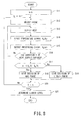
Fig. 8 is a flowchart showing operation of the liquid level sensing apparatus according to the above embodiments. - Embodiments of the present invention will be described below with reference to the accompanying drawings.
-
Fig. 1A shows a spentfuel storage pool 1 to which a liquidlevel sensing apparatus 20 according to the embodiments is applied. - A
rack 2 adapted to store plural spentfuel assemblies 3 is placed in a spent fuel storage pool 1 (hereinafter also referred to as a "liquid holding vessel 1"). Furthermore, a circulation cooler (not shown) is placed in the spentfuel storage pool 1 tocool pool water 4 whose temperature is raised by decay heat of thespent fuel assemblies 3. - If, for example, length a of the
spent fuel assemblies 3 is approximately 4.5 m (a = approximately 4.5 m) and height b of therack 2 is approximately 5 m (b = approximately 5 m), aliquid holding vessel 1 with a depth of about 12 m is required (d = approximately 12 m) and a liquid level of thepool water 4 is kept at a normal water level c = approximately 11 m. - Consequently, a high-level of radiation released from the
spent fuel assemblies 3 is blocked by thepool water 4 and kept from leaking out of theliquid holding vessel 1. - In the
liquid holding vessel 1, plural probes 10k (k = 0 to n) are placed with their tip portions spaced from one another in a height direction. - As shown in
Fig. 1B , the probe 10k is made up of an enclosingtube 11 in which atemperature sensor 12 and aheater 14 are enclosed, thetemperature sensor 12 being placed in a neighborhood of a detectingpoint 15 of theheater 14. - The
temperature sensor 12 is made up of a copper-constantan thermocouple and a sheath tube whose tip is closed, wherewires 13 of the thermocouple are contained in the sheath tube. A space between thewires 13 and sheath tube is filled with magnesium oxide serving as an insulating material. - A copper and constantan wires are welded together at the detecting
point 15. Other ends of thewires 13 are led to atemperature detecting unit 21, and ambient temperature around the detectingpoint 15 is measured based on a thermo-electromotive force detected at these ends. - In order to detect the liquid level of the
pool water 4 in deep part of theliquid holding vessel 1, thewires 13 of the thermocouple need to be extended in length. In this case, however, a large load is placed on thewires 13 of the thermocouple, and thus superior mechanical properties are required of thewires 13 themselves. Furthermore, noise in the detected thermo-electromotive force increases as thewires 13 of the thermocouple get longer, and thus it is necessary to adopt a thermocouple with a large thermo-electromotive force to increase a signal to noise ratio. - The
wires 13 of the copper-constantan thermocouple are superior to those of a commonly-used chromel-alumel thermocouple in capability to produce a larger thermo-electromotive force and suitability for low-temperature measurement, but inferior in mechanical properties. Thus, a sheathed copper-constantan thermocouple is adopted as thetemperature sensor 12 to ensure mechanical strength. - The sheathed copper-
constantan temperature sensor 12 is produced by inserting the wires of the copper-constantan thermocouple into the sheath tube before stretching, and then stretching the wires and sheath tube together. Being contained in the sheath tube, thewires 13 of the copper-constantan thermocouple does not become overloaded, which makes it possible to create thetemperature sensor 12 elongated in shape. - The enclosing
tube 11 contains thetemperature sensor 12 andheater 14. Also, the enclosingtube 11 is filled with magnesium oxide and externally placed in contact with the pool water 4 (liquid phase) and atmosphere (gas phase), where the magnesium oxide has a high heat conductivity. Thetemperature sensor 12 measures the temperatures of the pool water 4 (liquid phase) and atmosphere (gas phase) via the enclosingtube 11 and magnesium oxide while thermal energy from theheater 14 is released to the pool water 4 (liquid phase) and atmosphere (gas phase) by passing through the magnesium oxide and enclosingtube 11. - A voltage output Vk (k = 0 to n) on the order of millivolts is produced from the
temperature sensor 12 of the probe 10k configured as described above. Joule heat generated when an electric current is passed through theheater 14 varies in thermal diffusivity depending on whether the detectingpoint 15 of the probe 10k (k = 0 to n) is surrounded by a gas phase or liquid phase. This makes a difference in the voltage output Vk of thetemperature sensor 12. - The
temperature detecting unit 21 converts the week voltage output Vk received from the probe 10k (k = 0 to n) into a temperature signal VA(k) at a voltage level processible by an analog circuit and outputs the temperature signal to adetermination unit 30. Specifically, a voltage range of the voltage output Vk corresponding to a temperature measurement range of 0 to 100C° of the probe 10k is converted into the temperature signal VA(k) corresponding to a voltage range of 1 to 5 V. - A
heat supply unit 22 generates Joule heat by activating theheater 14 of a selected probe 10k (k = 0 to n) and thereby supplies thermal energy to around the detectingpoint 15 at a fixed flow rate. Note that a start time and duration t of the heat supply is controlled by thedetermination unit 30. - As shown in
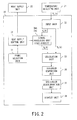
Fig. 2 (see alsoFig. 1 as appropriate), thedetermination unit 30 includes aprobe selection unit 31 adapted to select a probe 10 whoseheater 14 is to be activated from among the plural probes 10k (k = 0 to n), aninput unit 33 adapted to receive the voltage output Vk of the sensor 12 (Fig. 1 ) selected by theprobe selection unit 31, as the temperature signal VA(k) directly in the form of an analog quantity, asignal processing unit 34 adapted to output a processing signal VB(k) of the temperature signal VA(k) in synchronization with activation of the heater, acalculation unit 35 adapted to arithmetically process the temperature signal VA(k) and processing signal VB(k) and output a result, a gas/liquid discrimination unit 37 adapted to discriminate whether the detectingpoint 15 exists in a gas phase or liquid phase based on the output result of the arithmetic processing, and adisplay unit 38 adapted to indicate a discrimination result produced by the gas/liquid discrimination unit 37. - The
probe selection unit 31 selects a probe 10 to be used for liquid discrimination in theliquid holding vessel 1 from among the plural probes 10k (k = 0 to n). - A heat
supply control unit 32 causes thermal energy to be supplied to theheater 14 of the selected probe 10k at a fixed flow rate for the duration t and causes thesignal processing unit 34 to start processing in synchronization with the start time of the heat supply. - That is, the heat
supply control unit 32 outputs a voltage signal to theheat supply unit 22 to activate and deactivate the heater, thereby prescribing the duration t of heat supply, and outputs a same level of a voltage signal to thesignal processing unit 34 as well. - The
input unit 33 divides the received temperature signal VA(k) into two parts directly in the form of analog quantity and inputs one part directly to thecalculation unit 35 and inputs another part to thesignal processing unit 34. - The signal processing unit (hold circuit) 34A accepts as input a synchronizing signal from the heat
supply control unit 32, and outputs the processing signal VB(k) held at a level of the temperature signal VA(k) at the time of input. - That is, when the synchronizing signal from the heat
supply control unit 32 is set to OFF, thesignal processing unit 34A outputs the received temperature signal VA(k) as it is. Then, when the synchronizing signal is switched to ON, thesignal processing unit 34A continues to output the held processing signal VB(k) by maintaining an input voltage level of the temperature signal VA(k) inputted at that time until the synchronizing signal is switched to OFF again. - The
signal processing unit 34A is comprised, for example, of a hold circuit and the like, the hold circuit being made up of a combination of a switch contact and capacitor. - A graph in
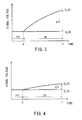
Fig. 3 shows time variations of the temperature signal VA and the processing signal VB thereof when the detectingpoint 15 of the probe 10k is exposed to a gas phase and the synchronizing signal of the heatsupply control unit 32 is switched from an OFF setting to an ON setting. - When a tip of the probe 10k is exposed to a gas phase in this way, the thermal energy supplied from the
heater 14 does not diffuse in the gas phase with low thermal diffusivity and thus greatly raises the ambient temperature around the detectingpoint 15. - Consequently, the temperature signal VA(k) of the
temperature sensor 12 increases with a time constant on the order of a few minutes and greatly diverges from the processing signal VB held at the level of the temperature signal VA(k) at the time of switching to ON. - Next, a graph in
Fig. 4 shows time variations of the temperature signal VA and the processing signal VB thereof when the detectingpoint 15 of the probe 10k is immersed in a liquid phase and the synchronizing signal of the heatsupply control unit 32 is switched from an OFF setting to an ON setting. When the tip of the probe 10k is immersed in a liquid phase in this way, the thermal energy supplied from theheater 14 is diffused in the liquid phase with high thermal diffusivity, and thus the ambient temperature around the detectingpoint 15 does not rise much. - Consequently, the temperature signal VA(k) of the
temperature sensor 12 reaches a state of equilibrium without diverging much from the processing signal VB held at the level of the temperature signal VA(k) at the time of switching to ON. - The calculation unit 35 (
Fig. 2 ) applies a subtraction process to the temperature signal VA(k) and processing signal VB(k) thereof, and outputs a difference to athreshold comparison unit 36. - During the duration t of heat supply, the
threshold comparison unit 36 outputs a determination signal to the gas/liquid discrimination unit 37, indicating whether or not a relationship between the output of thecalculation unit 35 and a threshold α satisfies determination formula (1) below. As the threshold α, an optimal value is established experimentally.
- When determination formula (1) is satisfied, the gas/
liquid discrimination unit 37 determines that the tip of the probe 10k is exposed to a gas phase and when determination formula (1) is not satisfied, the gas/liquid discrimination unit 37 determines that the tip of the probe 10k is immersed in a liquid phase. - The
display unit 38 is designed to present a discrimination result to an operator, indicating whether the tip portion of the probe 10k is in a liquid phase or gas phase and is implemented, for example, by a function to turn on and off a lamp. - As another operation example, the calculation unit 35 (
Fig. 2 ) applies a division process to the temperature signal VA(k) and processing signal VB(k) thereof, and outputs a quotient to thethreshold comparison unit 36. - During the duration t of heat supply, the
threshold comparison unit 36 outputs a determination signal to the gas/liquid discrimination unit 37, indicating whether or not a relationship between the output of thecalculation unit 35 and a threshold β satisfies determination formula (2) below. As the threshold β, an optimal value is established experimentally.
- When determination formula (2) is satisfied, the gas/
liquid discrimination unit 37 determines that the tip of the probe 10k is exposed to a gas phase and when determination formula (2) is not satisfied, the gas/liquid discrimination unit 37 determines that the tip of the probe 10k is immersed in a liquid phase. - Referring now to
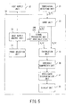
Fig. 5 , a second embodiment of the present invention will be described. - The second embodiment differs from the first embodiment in that a
signal processing unit 34B (34) of thedetermination unit 30 is a first order delay circuit adapted to output a first order delay response to a temperature signal. InFig. 5 , components same as or equivalent to those inFig. 2 are denoted by the same reference numerals as the corresponding components inFig. 2 , and redundant description thereof will be omitted. - In this way, since the
signal processing unit 34B is configured as a first order delay circuit, a processing signal VB(k) for use in gas/liquid discrimination can be outputted to thecalculation unit 35 in synchronization with heat supply without the need for a synchronizing signal from the heatsupply control unit 32. - Also, such a first order delay circuit can be implemented solely by a resistor and capacitor, eliminating the need for the
threshold comparison unit 36 to recognize the start time of the duration t of heat supply and thereby allowing a determination to be made based on determination formula (1) or (2) described above without regard to time. - Thus, the second embodiment allows configuration of the
determination unit 30 to be simplified. - A graph in
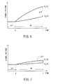
Fig. 6 shows time variations of the temperature signal VA and the processing signal VB thereof when the detectingpoint 15 of the probe 10k according to the second embodiment is exposed to a gas phase and the heatsupply control unit 32 is switched from an OFF setting to an ON setting. - During a period when the heat
supply control unit 32 is at an OFF setting, since the temperature signal VA(k) is in a steady state, the processing signal VB converges to the temperature signal VA(k). - However, when the heat
supply control unit 32 is switched to an ON setting, the temperature signal VA(k) from the gas phase rises greatly and shifts to a transient state. Then, the processing signal VB (k) which indicates a first order delay response to the transient state increases, following the temperature signal VA(k), but diverges greatly, being unable to keep up with a rate of change of the temperature signal VA(k). - Next, a graph in
Fig. 7 shows time variations of the temperature signal VA and the processing signal VB thereof when the detectingpoint 15 of the probe 10k according to the second embodiment is immersed in a liquid phase and the heatsupply control unit 32 is switched from an OFF setting to an ON setting. - During a period when the heat
supply control unit 32 is at an OFF setting, since the temperature signal VA(k) is in a steady state, the processing signal VB converges to the temperature signal VA(k). - Then, when the heat
supply control unit 32 is switched to an ON setting, the temperature signal VA(k) from the liquid phase rises and shifts to a transient state, but has a low rate of change. Consequently, the processing signal VB(k) which indicates a first order delay response to the transient state increases, following the temperature signal VA(k) with a small divergence. A time constant of the first order delay is, for example, around 60 seconds. - Operation of the liquid level sensing apparatus according to the above embodiments will be described with reference to a flowchart of
Fig. 8 (also toFig. 1 as appropriate). - Plural probes 10k (k = 0 to n) placed by varying their tip position in a height direction of the
liquid holding vessel 1 are selected one at a time beginning at the top (S11 and S12). Then, heat supply to theheater 14 is started by inputting the output Vk from thetemperature sensor 12 of the selected probe 10k as the temperature signal VA(k) directly in the form of an analog quantity (S13 and S14). - The processing signal VB(k) (hold value or first order delay response) of the temperature signal VA(k) is outputted in synchronization with the heat supply (S15), and the temperature signal VA(k) and processing signal VB(k) thereof are arithmetically processed and results are outputted until the duration t of heat supply expires (No or Yes in S16).
- If the output result of the arithmetic processing satisfies determination formula (1) or (2) described above, a decision of a gas phase is made (Yes in S17; S18), and if the output result does not satisfy determination formula (1) or (2), a decision of a liquid phase is made (No in S17; S19).
- Furthermore, a determination as to a gas phase or liquid phase is made using a next probe 10k (No in S20), and the liquid level in the
liquid holding vessel 1 is determined based on determination results produced using all the probes 10k (k = 0 to n) (Yes in S20; S21). - The liquid level sensing apparatus according to at least one of the embodiments described above can be made up solely of analog circuit, providing robustness against contingencies in nuclear facilities.
- Whereas a few embodiments of the present invention have been described, these embodiments are presented only by way of example, and not intended to limit the scope of the invention. These embodiments can be implemented in various other forms, and various omissions, replacements, changes, and combinations can be made without departing from the spirit of the invention. Such embodiments and modifications thereof are included in the spirit and scope of the invention as well as in the invention set forth in the appended claims and the scope of equivalents thereof.
- For example, although the liquid level is sensed by the plural probes 10k (k = 0 to n) mounted at fixed locations in the above embodiments, the liquid level may be sensed by moving the probes in a vertical direction.
Claims (5)
- A liquid level sensing apparatus which measures a liquid level in a liquid holding vessel based on temperature signals from a plurality of probes placed at fixed intervals in a vertical direction of the liquid holding vessel, where each of the probes contains a temperature sensor and a heater enclosed in the probe and the heater is placed in a neighborhood of a detecting point of the temperature sensor, the liquid level sensing apparatus comprising:a probe selection unit configured to select a probe whose heater is to be activated from among the plurality of probes;an input unit configured to receive an output of the temperature sensor of the probe selected by the probe selection unit, the output being received as a temperature signal directly in the form of an analog quantity;a signal processing unit configured to output a processing signal of the temperature signal in synchronization with activation of the heater;a calculation unit configured to arithmetically process the temperature signal and the processing signal and output a result;a gas/liquid discrimination unit configured to discriminate whether the detecting point exists in a gas phase or a liquid phase based on the output result of the arithmetic processing; anda display unit configured to indicate a discrimination result produced by the gas/liquid discrimination unit.
- The liquid level sensing apparatus according to claim 1, further comprising a liquid level determination unit configured to determine the liquid level based on the discrimination result produced by the gas/liquid discrimination unit.
- The liquid level sensing apparatus according to claim 1, wherein the calculation unit finds one of a difference and a quotient between the temperature signal and the processing signal and outputs a result.
- The liquid level sensing apparatus according to claim 1, wherein
the signal processing unit is one of a hold circuit and a first order delay circuit, where the hold circuit holds the processing signal at a level of the temperature signal at a start time of the heat supply and the first order delay circuit outputs a first order delay response to the temperature signal. - A liquid level sensing method for measuring a liquid level in a liquid holding vessel based on temperature signals from a plurality of probes placed at fixed intervals in a vertical direction of the liquid holding vessel, where each of the probes contains a temperature sensor and a heater enclosed in the probe and the heater is placed in a neighborhood of a detecting point of the temperature sensor, the liquid level sensing method comprising the steps of:selecting a probe whose heater is to be activated from among the plurality of probes;receiving an output of the temperature sensor of the selected probe as a temperature signal directly in the form of an analog quantity;outputting a processing signal of the temperature signal in synchronization with activation of the heater;arithmetically processing the temperature signal and the processing signal and outputting a result;discriminating whether the detecting point exists in a gas phase or a liquid phase based on the output result of the arithmetic processing; anddisplaying a discrimination result based on at least one of the selected probes.
Applications Claiming Priority (2)
| Application Number | Priority Date | Filing Date | Title |
|---|---|---|---|
| JP2012014554A JP5583153B2 (en) | 2012-01-26 | 2012-01-26 | Liquid level detection device and method |
| PCT/JP2013/051560 WO2013111847A1 (en) | 2012-01-26 | 2013-01-25 | Liquid level detection device and method |
Publications (2)
| Publication Number | Publication Date |
|---|---|
| EP2808658A1 true EP2808658A1 (en) | 2014-12-03 |
| EP2808658A4 EP2808658A4 (en) | 2015-12-23 |
Family
ID=48873559
Family Applications (1)
| Application Number | Title | Priority Date | Filing Date |
|---|---|---|---|
| EP13741506.3A Withdrawn EP2808658A4 (en) | 2012-01-26 | 2013-01-25 | Liquid level detection device and method |
Country Status (4)
| Country | Link |
|---|---|
| US (1) | US9423286B2 (en) |
| EP (1) | EP2808658A4 (en) |
| JP (1) | JP5583153B2 (en) |
| WO (1) | WO2013111847A1 (en) |
Families Citing this family (11)
| Publication number | Priority date | Publication date | Assignee | Title |
|---|---|---|---|---|
| US20140072086A1 (en) * | 2012-09-11 | 2014-03-13 | Ge-Hitachi Nuclear Energy Americas Llc | Method and system for measuring a spent fuel pool temperature and liquid level without external electrical power |
| US11017907B2 (en) | 2013-12-31 | 2021-05-25 | Nuscale Power, Llc | Nuclear reactor protection systems and methods |
| US20150323938A1 (en) * | 2014-05-09 | 2015-11-12 | Honeywell International Inc. | Temperature-based level detection and control method and apparatus |
| JP6401584B2 (en) * | 2014-11-25 | 2018-10-10 | 住友精密工業株式会社 | Liquid level detection device and liquid level detection system |
| JP6653161B2 (en) * | 2015-11-10 | 2020-02-26 | 日立Geニュークリア・エナジー株式会社 | Water level measurement system |
| JP2020514700A (en) * | 2016-12-30 | 2020-05-21 | ニュースケール パワー エルエルシー | Reactor protection system and method |
| JP6752169B2 (en) * | 2017-03-14 | 2020-09-09 | 日立Geニュークリア・エナジー株式会社 | Thermocouple liquid level measurement system |
| RU175490U1 (en) * | 2017-05-15 | 2017-12-06 | Общество с ограниченной ответственностью Научно-производственное объединение (ООО НПО "ИНКОР") | TEMPERATURE AND LIQUID CONTROL PROBE |
| US10760937B2 (en) * | 2017-09-08 | 2020-09-01 | RV Whisper LLC | System and method for measuring the level of fluid in a container |
| EP4053516A1 (en) * | 2021-03-05 | 2022-09-07 | HORIBA STEC, Co., Ltd. | Material supply system, program for a material supply system and material supply method |
| CN113280887A (en) * | 2021-05-14 | 2021-08-20 | 山西天泽煤化工集团股份公司 | Special algorithm liquid level meter |
Family Cites Families (42)
| Publication number | Priority date | Publication date | Assignee | Title |
|---|---|---|---|---|
| US2246563A (en) * | 1940-06-13 | 1941-06-24 | Universal Oil Prod Co | Liquid level indication and control |
| US3280627A (en) * | 1963-05-27 | 1966-10-25 | American Radiator & Standard | Liquid level sensor |
| US3905243A (en) * | 1973-09-11 | 1975-09-16 | Us Energy | Liquid-level sensing device |
| US4016758A (en) * | 1975-09-09 | 1977-04-12 | Taylor Julian S | Thermal gauge probe |
| JPS5593025A (en) * | 1979-01-08 | 1980-07-15 | Mitsubishi Electric Corp | Superconductive liquid level indicator |
| JPS5673320A (en) * | 1979-11-20 | 1981-06-18 | Toshiba Corp | Water level detecting device |
| JPS5676014A (en) * | 1979-11-28 | 1981-06-23 | Hitachi Ltd | Measuring device for liquid level at extreme low temperature |
| JPS56114718A (en) * | 1980-02-14 | 1981-09-09 | Toshiba Corp | Liquid level indicator |
| DE3022398A1 (en) * | 1980-06-14 | 1982-01-07 | Vdo Adolf Schindling Ag, 6000 Frankfurt | DEVICE FOR ELECTRICALLY MONITORING THE LEVEL OF A LIQUID CONTAINED IN A CONTAINER |
| US4356480A (en) * | 1980-09-11 | 1982-10-26 | Minnesota Mining And Manufacturing Company | Liquid level sensing circuitry |
| JPS5764115A (en) * | 1980-10-07 | 1982-04-19 | Japan Atom Energy Res Inst | Method and apparatus detecting liquid level |
| US4367462A (en) * | 1981-01-05 | 1983-01-04 | Minnesota Mining And Manufacturing Company | Liquid level sensing circuitry |
| DE3148383A1 (en) * | 1981-12-07 | 1983-06-16 | Siemens AG, 1000 Berlin und 8000 München | Device for measuring the filling level |
| JPS59107213A (en) * | 1982-12-10 | 1984-06-21 | Mitsubishi Electric Corp | Detector for liquid level |
| DE3408824A1 (en) * | 1984-03-10 | 1985-09-12 | Vdo Adolf Schindling Ag, 6000 Frankfurt | CIRCUIT ARRANGEMENT FOR ELECTROTHERMIC, AMBIENT TEMPERATURE COMPENSATED LEVEL MEASUREMENT |
| DE3423802A1 (en) * | 1984-06-28 | 1986-01-02 | Vdo Adolf Schindling Ag, 6000 Frankfurt | METHOD AND DEVICE FOR ELECTROTHERMIC, AMBIENT TEMPERATURE COMPENSATED LEVEL MEASUREMENT |
| JPS6176913A (en) * | 1984-09-25 | 1986-04-19 | Hitachi Ltd | Thermocouple type liquid-level meter |
| US4609913A (en) * | 1985-02-22 | 1986-09-02 | Wickes Manufacturing Company | Fluid level sensor |
| JPH0535293Y2 (en) * | 1988-03-18 | 1993-09-08 | ||
| US4929930A (en) * | 1988-10-24 | 1990-05-29 | Process Technology Inc. | Liquid level controller utilizing the rate of change of a thermocouple |
| US5111692A (en) * | 1990-03-27 | 1992-05-12 | Fluid Components, Inc. | Temperature compensated liquid level and fluid flow sensor |
| US5211904A (en) * | 1990-12-10 | 1993-05-18 | General Electric Company | In-vessel water level monitor for boiling water reactors |
| US5209115A (en) * | 1991-09-11 | 1993-05-11 | Intelsat | Liquid detector for thin-walled tanks operating in zero gravity |
| JPH05107099A (en) * | 1991-10-18 | 1993-04-27 | Chichibu Cement Co Ltd | Liquid level meter |
| JPH078729U (en) * | 1993-07-20 | 1995-02-07 | 清彦 三嘴 | Water level sensor |
| DE4434559C2 (en) * | 1994-09-28 | 1999-09-02 | Mannesmann Vdo Ag | Method and arrangement for operating a level sensor |
| US5730026A (en) * | 1995-03-31 | 1998-03-24 | Josef Maatuk | Microprocessor-based liquid sensor and ice detector |
| US5782131A (en) * | 1996-06-28 | 1998-07-21 | Lord; Richard G. | Flooded cooler with liquid level sensor |
| JPH10153681A (en) | 1996-11-22 | 1998-06-09 | Mitsubishi Heavy Ind Ltd | Water level measuring device for pressure suppression pool |
| JPH10332458A (en) * | 1997-05-27 | 1998-12-18 | Furukawa Electric Co Ltd:The | Cryogenic refrigerant liquid level gage |
| US6615658B2 (en) * | 1999-08-03 | 2003-09-09 | Charles Darwin Snelling | Method and apparatus for detecting the internal liquid level in a vessel |
| JP2002214020A (en) * | 2001-01-15 | 2002-07-31 | Erumekku Denshi Kogyo Kk | Liquid level measuring apparatus |
| US6536276B2 (en) * | 2001-02-27 | 2003-03-25 | Rosemont Aerospace Inc. | Apparatus and method to non-intrusively measure the level of liquid in a sealed container |
| US6546796B2 (en) * | 2001-03-15 | 2003-04-15 | Therm-O-Disc, Incorporated | Liquid level sensor |
| AUPR689601A0 (en) * | 2001-08-08 | 2001-08-30 | Refrigerant Monitoring Systems Pty Ltd | Liquid level sensor |
| JP2005134230A (en) * | 2003-10-30 | 2005-05-26 | Fuji Electric Retail Systems Co Ltd | Liquid level detection device |
| US20050126282A1 (en) * | 2003-12-16 | 2005-06-16 | Josef Maatuk | Liquid sensor and ice detector |
| EP2009431A1 (en) * | 2006-03-28 | 2008-12-31 | Mitsui Mining and Smelting Co., Ltd | Fluid identifying device and fluid identifying method |
| US7828960B1 (en) * | 2007-05-16 | 2010-11-09 | Thermaco, Inc. | F.O.G. separator control |
| JP5865614B2 (en) | 2011-06-27 | 2016-02-17 | 株式会社東芝 | Water level detector for nuclear power plant |
| WO2013003891A1 (en) * | 2011-07-01 | 2013-01-10 | Breville Pty Limited | Method and apparatus for water level sensing |
| US9091583B2 (en) * | 2012-11-16 | 2015-07-28 | Amphenol Thermometrics, Inc. | Fluid level sensor system and method |
-
2012
- 2012-01-26 JP JP2012014554A patent/JP5583153B2/en active Active
-
2013
- 2013-01-25 US US14/374,272 patent/US9423286B2/en not_active Expired - Fee Related
- 2013-01-25 EP EP13741506.3A patent/EP2808658A4/en not_active Withdrawn
- 2013-01-25 WO PCT/JP2013/051560 patent/WO2013111847A1/en active Application Filing
Also Published As
| Publication number | Publication date |
|---|---|
| EP2808658A4 (en) | 2015-12-23 |
| US9423286B2 (en) | 2016-08-23 |
| US20150040660A1 (en) | 2015-02-12 |
| JP2013156036A (en) | 2013-08-15 |
| WO2013111847A1 (en) | 2013-08-01 |
| JP5583153B2 (en) | 2014-09-03 |
Similar Documents
| Publication | Publication Date | Title |
|---|---|---|
| US9423286B2 (en) | Liquid level sensing apparatus and method | |
| US4590797A (en) | Thermal system for measuring liquid levels | |
| EP2995913B1 (en) | Robust dynamical method for detecting the level of a liquid using resistance temperature detectors | |
| US7926345B2 (en) | Apparatus for measuring a filling level | |
| RU2469278C2 (en) | Method and device for monitoring level of liquid in reservoir | |
| US20130177122A1 (en) | Reactor Water-Level/Temperature Measurement Apparatus | |
| US20060042375A1 (en) | Fluid-level sensing and fluid detection | |
| JP6529401B2 (en) | Apparatus, method and program for detecting gas leakage of radioactive substance sealed container | |
| EP0066516B1 (en) | Device for checking the coolant condition in a nuclear reactor | |
| EP2306066A1 (en) | Apparatus for determining liquid volume | |
| JP2013108905A (en) | Reactor water level instrumentation system | |
| JP5826605B2 (en) | Apparatus and method for detecting water level in spent fuel storage pool | |
| JPWO2018123854A1 (en) | Liquid level gauge, vaporizer equipped with the same, and liquid level detection method | |
| JP2013007721A (en) | Water level temperature detector of nuclear power plant | |
| RU2487323C2 (en) | Electric heating element | |
| US4781469A (en) | Detecting proximity or occurrence of change of phase within a fluid | |
| JP6382609B2 (en) | Liquid level measurement system and method | |
| JP2013113808A (en) | Liquid level measuring device, method and program | |
| US11326974B2 (en) | Gas leakage detection method and gas leakage detection apparatus in horizontally-installed canister | |
| RU2755841C1 (en) | Apparatus for measuring the parameters of a medium | |
| US3369401A (en) | Temperature-gradient-insensitive resistance-type liquid metal level detector | |
| Takeyama et al. | Phase Detection aided Thermometry and Its Application to Natural Convective Subcooled Flow Boiling in a Narrow Gap | |
| RU2523085C1 (en) | Liquid nitrogen level alarm | |
| JP2005003458A (en) | Sensing method for inside pressure creep rupture | |
| JP2018025503A (en) | Liquid level measurement device, liquid level measurement evaluation method |
Legal Events
| Date | Code | Title | Description |
|---|---|---|---|
| PUAI | Public reference made under article 153(3) epc to a published international application that has entered the european phase |
Free format text: ORIGINAL CODE: 0009012 |
|
| 17P | Request for examination filed |
Effective date: 20140725 |
|
| AK | Designated contracting states |
Kind code of ref document: A1 Designated state(s): AL AT BE BG CH CY CZ DE DK EE ES FI FR GB GR HR HU IE IS IT LI LT LU LV MC MK MT NL NO PL PT RO RS SE SI SK SM TR |
|
| DAX | Request for extension of the european patent (deleted) | ||
| RA4 | Supplementary search report drawn up and despatched (corrected) |
Effective date: 20151124 |
|
| RIC1 | Information provided on ipc code assigned before grant |
Ipc: G21C 17/035 20060101ALI20151118BHEP Ipc: G21C 19/07 20060101ALI20151118BHEP Ipc: G01F 23/24 20060101ALN20151118BHEP Ipc: G01F 23/22 20060101AFI20151118BHEP |
|
| STAA | Information on the status of an ep patent application or granted ep patent |
Free format text: STATUS: THE APPLICATION HAS BEEN WITHDRAWN |
|
| 18W | Application withdrawn |
Effective date: 20160906 |