EP2808635A1 - Drying furnace unit and drying furnace - Google Patents
Drying furnace unit and drying furnace Download PDFInfo
- Publication number
- EP2808635A1 EP2808635A1 EP13740522.1A EP13740522A EP2808635A1 EP 2808635 A1 EP2808635 A1 EP 2808635A1 EP 13740522 A EP13740522 A EP 13740522A EP 2808635 A1 EP2808635 A1 EP 2808635A1
- Authority
- EP
- European Patent Office
- Prior art keywords
- drying oven
- air
- vent
- sheet
- flow
- Prior art date
- Legal status (The legal status is an assumption and is not a legal conclusion. Google has not performed a legal analysis and makes no representation as to the accuracy of the status listed.)
- Withdrawn
Links
Images




Classifications
-
- F—MECHANICAL ENGINEERING; LIGHTING; HEATING; WEAPONS; BLASTING
- F26—DRYING
- F26B—DRYING SOLID MATERIALS OR OBJECTS BY REMOVING LIQUID THEREFROM
- F26B3/00—Drying solid materials or objects by processes involving the application of heat
- F26B3/28—Drying solid materials or objects by processes involving the application of heat by radiation, e.g. from the sun
- F26B3/283—Drying solid materials or objects by processes involving the application of heat by radiation, e.g. from the sun in combination with convection
-
- F—MECHANICAL ENGINEERING; LIGHTING; HEATING; WEAPONS; BLASTING
- F26—DRYING
- F26B—DRYING SOLID MATERIALS OR OBJECTS BY REMOVING LIQUID THEREFROM
- F26B13/00—Machines and apparatus for drying fabrics, fibres, yarns, or other materials in long lengths, with progressive movement
- F26B13/10—Arrangements for feeding, heating or supporting materials; Controlling movement, tension or position of materials
-
- F—MECHANICAL ENGINEERING; LIGHTING; HEATING; WEAPONS; BLASTING
- F26—DRYING
- F26B—DRYING SOLID MATERIALS OR OBJECTS BY REMOVING LIQUID THEREFROM
- F26B21/00—Arrangements for supplying or controlling air or other gases for drying solid materials or objects
- F26B21/50—Ducting arrangements from the source of air or other gases to the materials or objects being dried
- F26B21/55—Outlets for directing or distributing the air or other gases
-
- F—MECHANICAL ENGINEERING; LIGHTING; HEATING; WEAPONS; BLASTING
- F26—DRYING
- F26B—DRYING SOLID MATERIALS OR OBJECTS BY REMOVING LIQUID THEREFROM
- F26B3/00—Drying solid materials or objects by processes involving the application of heat
- F26B3/28—Drying solid materials or objects by processes involving the application of heat by radiation, e.g. from the sun
- F26B3/30—Drying solid materials or objects by processes involving the application of heat by radiation, e.g. from the sun from infrared-emitting elements
Definitions
- the present invention relates to a drying oven unit and a drying oven.
- Patent Literature (PTL) 1 discloses a drying oven in which four drying zones having an entrance and an exit are coupled together in series along a predetermined direction. A top of each drying zone is provided with an air inlet and an air outlet. An air supply means for forcibly supplying air is attached to each air inlet. An exhaust means for forcibly exhausting air is attached to each air outlet.
- the direction of air flow in each drying zone is the same as, and parallel to, a sheet conveying direction.
- PTL 1 explains that the direction of air flow may be made opposite the sheet conveying direction, but for efficient removal of evaporated organic solvent, it is preferable that the direction of air flow be the same as and parallel to the sheet conveying direction.
- PTL 1 neither describes nor suggests the technical idea of freely changing the air flow in each drying zone in the drying oven. Since the air supply means is attached to the air inlet and the exhaust means is attached to the air outlet, the direction of air flow is fixed to the direction from the air inlet to the air outlet. To reverse the air flow, the exhaust means is to be attached to the air inlet and the air supply means is to be attached to the air outlet. In this case, however, the direction of air flow is fixed to the direction from the air outlet to the air inlet. This means that the flow of air cannot be freely changed.
- a primary object of the present invention is to provide a drying oven unit capable of freely changing the flow of air, and a drying oven including the drying oven unit.
- a drying oven unit includes an oven body; a conveyance path passing through the oven body in a predetermined direction, the conveyance path being a path along which a sheet coated with slurry on at least one side thereof is conveyed in the predetermined direction; first and second vents provided at respective ends of the conveyance path such that ambient gas flows along a slurry coated surface of the sheet; air supply means connected to the first vent and the second vent; and air-flow switching means for switching between permitting air from the air supply means to flow from the first vent to the second vent along the coated surface of the sheet and permitting air from the air supply means to flow from the second vent to the first vent along the coated surface of the sheet.
- air from the air supply means can be set to flow either from the first vent to the second vent along the coated surface of the sheet, or reversely from the second vent to the first vent along the coated surface of the sheet.
- the flow of ambient gas can be freely changed by switching the air-flow switching means.
- the air supply means may supply either hot air (having, for example, a temperature of 60°C to 150°C) or cool air (having, for example, a room temperature or a temperature of 40°C to 50°C).
- the ambient gas is not limited to a specific one, but may be, for example, air or inert gas (such as nitrogen).
- the drying oven unit according to the present invention preferably includes an infrared heater along the conveyance path, the infrared heater being disposed to face the coated surface of the sheet.
- the infrared heater to be used may be one in which the outer periphery of a filament is concentrically covered by a plurality of pipes functioning as filters that absorb infrared radiation having a wavelength of greater than 3.5 ⁇ m, and a flow path for a cooling fluid that suppresses an increase in surface temperature of the infrared heater is formed between the pipes (see Japanese Patent No. 4790092 ).
- the drying oven unit according to the present invention preferably includes air-volume regulating means for regulating a volume of air from the air supply means. This makes it possible to freely change the volume of air as well as the direction of air flow.
- the sheet may be coated with slurry on both sides thereof, and the first and second vents may be provided for each of the slurry coated surfaces.
- both the slurry coated surfaces of the sheet can be dried simultaneously. This simultaneous drying requires less time than drying each surface at a time, and thus can enhance production efficiency.
- a drying oven according to the present invention is formed by coupling together a plurality of drying oven units, each being the drying oven unit described above, such that conveyance paths are arranged in series along the predetermined direction.
- the flow of ambient gas can be freely changed for each drying oven unit by switching the air-flow switching means in each drying oven unit.
- the directions of air flows in adjacent drying oven units can be made the same or opposite.
- the air flows can either collide with, or move away from, each other.
- those at both ends of the drying oven may be set by the air-flow switching means such that the flows of air are directed from the outside to the inside.
- air is not easily blown out of either the conveyance path in the drying oven unit at one end of the drying oven or the conveyance path in the drying oven unit at the other end of the drying oven. Therefore, it is possible to maintain good environment in the room where the drying oven is installed.
- the drying oven according to the present invention may include detecting means for detecting the amount of solvent evaporated from the slurry in each drying oven unit; and control means for controlling the air-flow switching means such that if the amount of solvent evaporated exceeds a predetermined value in successive drying oven units, flows of air in the successive drying oven units are directed in the same direction.
- control means for controlling the air-flow switching means such that if the amount of solvent evaporated exceeds a predetermined value in successive drying oven units, flows of air in the successive drying oven units are directed in the same direction.
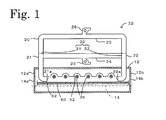
- Fig. 1 is a vertical cross-sectional view of a drying oven unit 10.
- Fig. 2 is a vertical cross-sectional view of an infrared heater 36.
- Fig. 3 is a cross-sectional view taken along line A-A of Fig. 2 .
- the drying oven unit 10 includes an oven body 12, a conveyance path 14, a pipe structure 20 having first and second vents 21a and 22a, a hot air generator 26, an exhaust blower 28, an air-flow switching valve 30, and infrared heaters 36.
- the oven body 12 is a heat insulating structure substantially in the shape of a substantially rectangular parallelepiped.
- the oven body 12 has a front end face 12a and a rear end face 12b provided with an opening 14a and an opening 14b, respectively.
- a distance between the front end face 12a and the rear end face 12b of the oven body 12 is 2 m to 6 m.
- a conveyance path 14 is a path extending from the opening 14a to the opening 14b.
- the conveyance path 14 horizontally passes through the oven body 12.
- a sheet 60 coated with slurry on one side thereof passes along the conveyance path 14.
- the sheet 60 is introduced through the opening 14a into the oven body 12, horizontally conveyed in the oven body 12, and discharged through the opening 14b.
- the pipe structure 20 has a first pipe segment 21 vertically passing through a ceiling of the oven body 12 at a location near the front end face 12a, a second pipe segment 22 vertically passing through the ceiling of the oven body 12 at a location near the rear end face 12b, a third pipe segment 23 connecting an upper end of the first pipe segment 21 to an upper end of the second pipe segment 22, and a fourth pipe segment 24 connecting a midpoint of the first pipe segment 21 to a midpoint of the second pipe segment 22. That is, the third pipe segment 23 and the fourth pipe segment 24 are paths that connect the first pipe segment 21 in parallel with the second pipe segment 22.
- the first pipe segment 21 is bent inside the oven body 12 to allow a lower end portion thereof to face in the horizontal direction.
- the first vent 21a which is an opening at the lower end of the first pipe segment 21, is open toward the rear end face 12b.
- the second pipe segment 22 is bent inside the oven body to allow a lower end portion thereof to face in the horizontal direction. Therefore, the second vent 22a, which is an opening at the lower end of the second pipe segment 22, is open toward the front end face 12a.
- the first vent 21a and the second vent 22a are positioned to face each other.
- the first vent 21a and the second vent 22a may be located at different heights, but are often located at the same height. Therefore, the flow of air from one of the first and second vents 21a and 22a into the other is directed along the slurry coated surface 62 of the sheet 60.
- the hot air generator 26 is attached to the fourth pipe segment 24.
- the hot air generator 26 is configured to supply hot air to the inside of the fourth pipe segment 24.
- the hot air generator 26 is capable of regulating the air volume.
- the exhaust blower 28 is attached to the third pipe segment 23.
- the exhaust blower 28 has the function of discharging gas in the third pipe segment 23 to the outside.
- the exhaust blower 28 is also capable of regulating the air volume.
- the air-flow switching valve 30 includes a first valve 31 at a joint between the first pipe segment 21 and the fourth pipe segment 24, and a second valve 32 at a joint between the second pipe segment 22 and the fourth pipe segment 24.
- the first valve 31 is switched between a position (indicated by a solid line in Fig. 1 and referred to as an air supply position) for both permitting communication between the first pipe segment 21 and the fourth pipe segment 24 and blocking communication between the first pipe segment 21 and the third pipe segment 23 and a position (indicated by a dotted line in Fig. 1 and referred to as an exhaust position) for both blocking communication between the first pipe segment 21 and the fourth pipe segment 24 and permitting communication between the first pipe segment 21 and the third pipe segment 23.
- the second valve 32 is switched between a position (indicated by a solid line in Fig. 1 and referred to as an exhaust position) for both blocking communication between the second pipe segment 22 and the fourth pipe segment 24 and permitting communication between the second pipe segment 22 and the third pipe segment 23 and a position (indicated by a dotted line in Fig. 1 and referred to as an air supply position) for both permitting communication between the second pipe segment 22 and the fourth pipe segment 24 and blocking communication between the second pipe segment 22 and the third pipe segment 23.
- Each of the valves 31 and 32 may be switched either manually or electrically by an electromagnetic solenoid.
- a piping system for circulation may be added between pipes to compensate for part of supply air with part of exhaust air.
- each infrared heater 36 includes a heater main body 42 formed by surrounding a filament 38 with an inner pipe 40, an outer pipe 44 surrounding the heater main body 42, caps 46 each having a cylindrical shape with a bottom and airtightly fitted over the corresponding end of the outer pipe 44, and a flow path 48 formed between the heater main body 42 and the outer pipe 44 and permitting circulation of a cooling fluid.
- the filament 38 is electrically heated to a temperature of 700°C to 1200°C, and emits infrared radiation with a peak wavelength of around 3 ⁇ m.
- An electric wire 38a connected to the filament 38 extends through a wire lead portion 46a of each cap 46 and is airtightly led to the outside.
- the inner pipe 40 is made of silica glass, borosilicate crown glass, or the like.
- the inner pipe 40 functions as a filter that transmits infrared radiation having a wavelength of 3.5 ⁇ m or less and absorbs infrared radiation having a wavelength of greater than 3.5 ⁇ m.
- the heater main body 42 is supported by holders 50 disposed inside the respective caps 46 at both ends thereof.
- the outer pipe 44 is made of silica glass, borosilicate crown glass, or the like.
- the outer pipe 44 functions as a filter that transmits infrared radiation having a wavelength of 3.5 ⁇ m or less and absorbs infrared radiation having a wavelength of greater than 3.5 ⁇ m.
- Each cap 46 has a fluid port 46b.
- the flow path 48 allows a cooling fluid to flow from one fluid port 46b to the other fluid port 46b. Examples of the cooling fluid flowing through the flow path 48 include air and inert gas. The cooling fluid cools the inner pipe 40 and the outer pipe 44 by contacting them to remove heat therefrom.
- infrared radiation having a peak wavelength of around 3 ⁇ m When infrared radiation having a peak wavelength of around 3 ⁇ m is emitted from the filament 38 of the infrared heater 36, infrared radiation having a wavelength of 3.5 ⁇ m or less passes through the inner pipe 40 and the outer pipe 44 and is applied to the slurry coated surface 62 of the sheet 60 passing along the conveyance path.
- Infrared radiation having a wavelength of 3.5 ⁇ m or less is said to be highly capable of breaking hydrogen bonding in an organic solvent contained in the slurry coated surface 62 of the sheet 60, and can efficiently evaporate the organic solvent.
- the inner pipe 40 and the outer pipe 44 absorb infrared radiation having a wavelength of greater than 3.5 ⁇ m, but are cooled by the cooling fluid flowing through the flow path 48. Therefore, the inner pipe 40 and the outer pipe 44 can be kept at a temperature below the ignition point of the organic solvent evaporated from the slurry coated surface 62.
- the infrared heater 36 is disposed in an inner space of each arched groove 52 in a reflective plate near the ceiling of the oven body 12. Like the infrared heater 36, the arched groove 52 extends in a direction orthogonal to the conveyance direction.
- the cross section of the arched groove 52 has a curved shape, such as a parabolic shape, an elliptical arc shape, or a circular arc shape.
- the infrared heater 36 is disposed at a focal or central point of the cross section of the arched groove 52.
- the infrared radiation having a wavelength of 3.5 ⁇ m or less emitted from the infrared heater 36 is reflected by the arched groove 52 and efficiently applied to the slurry coated surface 62.
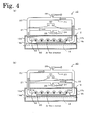
- FIG. 4 illustrates switching of air flow in the drying oven unit 10.
- Fig. 4(a) illustrates the drying oven unit 10 in which hot air flows from the first vent 21a to the second vent 22a
- Fig. 4(b) illustrates the drying oven unit 10 in which hot air flows from the second vent 22a to the first vent 21a.
- the first valve 31 is set to the air supply position and the second valve 32 is set to the exhaust position as illustrated in Fig. 4(a) .
- the first valve 31 is set to the position for both permitting communication between the first pipe segment 21 and the fourth pipe segment 24 and blocking communication between the first pipe segment 21 and the third pipe segment 23.
- the second valve 32 is set to the position for both blocking communication between the second pipe segment 22 and the fourth pipe segment 24 and permitting communication between the second pipe segment 22 and the third pipe segment 23.
- hot air supplied from the hot air generator 26 to the fourth pipe segment 24 passes through the first pipe segment 21 and is blown out of the first vent 21a. Gas passing through the second vent 22a and the second pipe segment 22 is discharged from the third pipe segment 23 by the exhaust blower 28.
- hot air flows from the first vent 21a to the second vent 22a.
- the second valve 32 is set to the air supply position and the first valve 31 is set to the exhaust position as illustrated in Fig. 4(b) .
- the second valve 32 is set to the position for both permitting communication between the second pipe segment 22 and the fourth pipe segment 24 and blocking communication between the second pipe segment 22 and the third pipe segment 23.
- the first valve 31 is set to the position for both blocking communication between the first pipe segment 21 and the fourth pipe segment 24 and permitting communication between the first pipe segment 21 and the third pipe segment 23.
- hot air supplied from the hot air generator 26 to the fourth pipe segment 24 passes through the second pipe segment 22 and is blown out of the second vent 22a. Gas passing through the first vent 21a and the first pipe segment 21 is discharged from the third pipe segment 23 by the exhaust blower 28.
- hot air flows from the second vent 22a to the first vent 21a.
- a drying oven 70 which is formed by coupling together a plurality of drying oven units 10 such that a plurality of conveyance paths 14 are arranged in a straight line along the horizontal direction.
- Fig. 5 illustrates the drying oven 70.
- Fig. 6 illustrates a relationship between an evaporation curve and an air flow direction in each of the drying oven units 10 included in the drying oven 70.
- the drying oven 70 is formed by coupling the front end face 12a of each drying oven unit 10, with bolts, to the rear end face 12b of the adjacent drying oven unit 10.
- a gasket (not shown) ensures airtightness of the opening 14a of the front end face 12a and the opening 14b of the rear end face 12b.
- the gasket may be made of any material resistant to an organic solvent.
- the gasket may be made of polytetrafluoroethylene.
- the bolt coupling may not be necessary.
- the drying oven 70 is installed in a drying oven installation room, the exhaust blowers 28 may be installed outside the drying oven installation room. Even when the exhaust blowers 28 are installed indoors, since each blower outlet is connected through a duct to an air outlet leading to the outside of the building, air discharged from the exhaust blower 28 is not released into the drying oven installation room.
- drying oven units 10 are coupled together to form the drying oven 70 as illustrated in Fig. 6 .
- the drying oven units 10 are referred to as a drying oven unit U1, a drying oven unit U2, ..., and a drying oven unit U7, from the left in this order.
- the sheet 60 is unwound from a roll 72 at the left end of the drying oven 70, coated with slurry on the upper surface thereof by a coater (not shown) immediately before being introduced into the drying oven 70, and introduced through the opening 14a of the drying oven unit U1 into the drying oven 70.
- the organic solvent is evaporated from the slurry coated surface 62, and the evaporated organic solvent is discharged to the outside by the exhaust blower 28.
- the sheet 60 is eventually taken out through the opening 14b of the drying oven unit U7 and wound on a roll 74 at the right end of the drying oven 70.
- the organic solvent is evaporated from the slurry coated surface 62 by the action of infrared radiation from the infrared heaters 36 and hot air from the hot air generators 26.
- the resulting evaporation curve has a profile shown in Fig. 6 .
- the evaporation curve shows that immediately after the sheet 60 is introduced into the drying oven unit U1, the amount of evaporation of the organic solvent is small because the sheet temperature is not sufficiently high.
- the amount of evaporation is very large in the drying oven units U2 to U4. Then in the drying oven unit U5 and the subsequent units, that is, after evaporation of most of the organic solvent, the amount of evaporation is small.
- the solvent may accumulate unless all flows of hot air are directed in the same direction. That is, if the direction of hot air flow in any of the drying oven units U2 to U4 is different from that in the other units, stagnation of air flow occurs in an area where the directions of hot air flows are different (for example, where flows of hot air collide with, or move away from, each other) and the evaporated solvent may accumulate in that area. However, since all the flows of hot air in these drying oven units are directed in the same direction here, the evaporated solvent is less likely to accumulate in any area.
- the drying oven 70 has at least one connection point at which air flows are opposed to each other. It is preferable that the connection point be set to a position where the amount of solvent evaporation is small. However, since the shape of the evaporation curve varies depending on the type of slurry coated, it is necessary to move the connection point to an appropriate position in accordance with the type of the slurry. Such a manipulation is possible in the present invention, because the direction of air flow can be changed for each drying oven unit.
- the sheet 60 having the slurry coated surface 62 is not limited to a specific type.
- a sheet coated with electrodes for a lithium-ion secondary battery may be used.
- a metal sheet such as an aluminum or copper sheet, coated with electrode slurry made by blending a positive-electrode active material (or negative-electrode active material) with a binder, a conductive material, and an organic solvent.
- a fired ceramic sheet coated with an unfired ceramic compact may be used.
- Examples of such a sheet include a fired ceramic sheet coated with slurry made by blending ceramic particles with a binder and water (or organic solvent).
- hot air can be set to flow either from the first vent 21a to the second vent 22a along the slurry coated surface 62 of the sheet 60, or reversely from the second vent 22a to the first vent 21a along the slurry coated surface 62 of the sheet 60.
- the flow of air can be freely changed by switching the air-flow switching valve 30.
- the infrared heaters 36 are provided, even when it is difficult to dry the slurry coated surface 62 with hot air alone, the slurry coated surface 62 can be dried in a short time by using the infrared heaters 36 along with hot air.
- the infrared heaters 36 emit infrared radiation having a wavelength of 3.5 ⁇ m or less and keep the heater surface temperature as low as below the ignition point of the organic solvent. Therefore, it is possible not only to efficiently evaporate the organic solvent, but also prevent the organic solvent from being ignited.
- the hot air generator 26 and the exhaust blower 28 are capable of regulating the air volume, it is possible to freely change the volume as well as the direction of hot air.
- the drying oven 70 is formed by coupling the drying oven units U1 to U7 together such that the conveyance paths are arranged in series along the conveyance direction of the sheet 60. Therefore, by switching the air-flow switching valve 30 in each of the drying oven units U1 to U7, the flow of air can be freely changed for each of the drying oven units U1 to U7.
- the directions of hot air flows in adjacent drying oven units can be made the same or opposite. When the directions are made opposite, the flows of hot air can either collide with, or move away from, each other.
- the flow of hot air in each of the drying oven units U1 to U7 can be regulated in accordance with the evaporation curve.
- each of the drying oven units U1 and U7 at the respective ends of the drying oven 70 is set such that the flow of hot air is directed from the outside to the inside. Therefore, the hot air is not easily blown out of either the conveyance path 14 in the drying oven unit U1 or the conveyance path 14 in the drying oven unit U7. It is thus possible to maintain good environment in the drying oven installation room where the drying oven 70 is installed.
- the drying oven unit 10 and the drying oven 70 are designed to dry the sheet 60 coated with slurry on one side thereof.
- a drying oven unit 110 and a drying oven 170 may be designed to dry a sheet 160 coated with slurry on both sides thereof.
- the same components as those of the drying oven unit 10 and the drying oven 70 described above are given the same reference numerals and their description will be omitted.
- the drying oven unit 110 illustrated in Fig. 7 is used to dry the sheet 160 having slurry coated surfaces 162 on both sides.
- the drying oven unit 110 includes the pipe structure 20 having the first and second vents 21a and 22a, the hot air generator 26, the exhaust blower 28, the air-flow switching valve 30, and the infrared heaters 36 for each of the slurry coated surfaces 162.
- the direction of air flow can be switched by means of the first and second valves 31 and 32 of the air-flow switching valve 30.
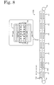
- the drying oven 170 illustrated in Fig. 8 is formed by coupling a plurality of drying oven units 110 together such that the conveyance paths 14 are arranged in a straight line along the horizontal direction.
- the drying oven units 110 are coupled together in the same manner as in the drying oven 70.
- the drying oven units 110 are referred to as a drying oven unit U1, a drying oven unit U2, ..., and a drying oven unit U7, from the left in this order.
- the sheet 160 is unwound from the roll 72 at the left end of the drying oven 170, coated with slurry on both the upper and lower surfaces thereof by a rotor (not shown) immediately before being introduced into the drying oven 70, and introduced through the opening 14a of the drying oven unit U1 into the drying oven 70.
- the organic solvent is evaporated from the upper and lower slurry coated surfaces 162 and the evaporated organic solvent is discharged by each exhaust blower 28 to the outside.
- the sheet 160 is eventually taken out through the opening 14b of the drying oven unit U7 and wound on the roll 74 at the right end of the drying oven 170.
- the direction of hot air flow in each of the drying oven units U1 to U7 is determined on the basis of an evaporation curve obtained by a numerical simulation. In the drying oven units U1 and U7 at the respective ends of the drying oven 170, the flow of hot air is directed from the outside to the inside.
- the drying oven units 110 and the drying oven 170 can simultaneously dry both the slurry coated surfaces of the sheet 160. This simultaneous drying requires less time than drying each surface at a time, and thus can enhance production efficiency.
- the direction of hot air flow in each of the drying oven units U1 to U7 is determined on the basis of the evaporation curve.
- the direction of hot air flow may be changed while the sheet 60 is being dried.
- the direction of air flow may be changed either manually or automatically.
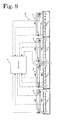
- An example of automatically changing the direction of air flow will be described with reference to Fig. 9 .
- a sensor S for detecting the amount of solvent evaporated from the slurry coated surface 62 is attached to each drying oven unit 10 of the drying oven 70. Solenoid valves are used as the first and second valves 31 and 32. Additionally, a controller C is prepared.
- Each sensor S is connected to the corresponding input port of the controller C, and the first and second valves 31 and 32 are connected to the corresponding output ports of the controller C.
- a signal related to the amount of solvent evaporation output from each sensor S is input to the controller C.
- a driving signal is output to the first and second valves 31 and 32.
- the controller C determines whether the amount of solvent evaporation exceeds a predetermined threshold. If the threshold is exceeded, the controller C controls the first and second valves 31 and 32 such that the flows of hot air in the successive drying oven units are directed in the same direction.
- the type of the sensor S may be selected depending on the type of the organic solvent used in the slurry. For example, a hydrocarbon (HC) sensor may be selected for a hydrocarbon solvent, and an alcohol sensor may be selected for an alcohol solvent.
- each conveyance path 14 may be provided with some supporting rollers that support the sheet 60 from below. This can prevent the sheet 60 from being bent by gravity.
- the sheet 160 has the slurry coated surfaces 162 on both sides as illustrated in Figs. 7 and 8 , it is preferable not to provide any supporting rollers. This is because the slurry coated surfaces 62 may come into contact with such supporting rollers, and unintended surface irregularities may be produced.
- the infrared heaters 36 are mounted in the ceiling of the oven body 12 in the embodiments described above.
- the infrared heaters 36 may not be provided if the slurry coated surface 62 of the sheet 60 is thin enough to be sufficiently dried with hot air alone.
- Each infrared heater 36 used in the embodiments described above is one in which the outer periphery of the filament 38 is concentrically covered by a plurality of pipes 40 and 44 functioning as filters that absorb infrared radiation having a wavelength of greater than 3.5 ⁇ m, and the flow path 48 for a cooling fluid that suppresses an increase in surface temperature of the infrared heater 36 is formed between the pipes 40 and 44.
- other types of infrared heaters may be used.
- drying oven 70 is formed by a plurality of drying oven units 10 arranged in series in the embodiments described above, a drying oven formed by a single drying oven unit 10 may be used.
- an inert gas such as nitrogen, may be used instead of air.
- the air supply means is not particularly limited to this.
- a cool air generator that generates cool air having a temperature of 40°C to 50°C may be used as the air supply means.
- the present invention is applicable in industries that involve drying sheets coated with slurry.
- industries include battery industries that manufacture electrode coatings for lithium-ion secondary batteries, ceramic industries that manufacture ceramic layered products formed by two-layer ceramic sintered bodies, and film manufacturing industries that manufacture optical film products.
- drying oven unit 12 oven body, 12a front end face, 12b rear end face, 14 conveyance path, 14a opening, 14b opening, 20 pipe structure, 21 first pipe segment, 21a first vent, 22 second pipe segment, 22a second vent, 23 third pipe segment, 24 fourth pipe segment, 26 hot air generator, 28 exhaust blower, 30 air-flow switching valve, 31 first valve, 32 second valve, 36 infrared heater, 38 filament, 38a electric wire, 40 inner pipe, 42 heater main body, 44 outer pipe, 46 cap, 46a wire lead portion, 46b fluid port, 48 flow path, 50 holder, 52 arched groove, 60 sheet, 62 slurry coated surface, 70 drying oven, 72 roll, 74 roll, 110 drying oven unit, 160 sheet, 162 slurry coated surface, 170 drying oven, C controller, S sensor, U1-U7 drying oven unit
Landscapes
- Engineering & Computer Science (AREA)
- Mechanical Engineering (AREA)
- General Engineering & Computer Science (AREA)
- Life Sciences & Earth Sciences (AREA)
- Microbiology (AREA)
- Textile Engineering (AREA)
- Drying Of Solid Materials (AREA)
- Coating Apparatus (AREA)
Abstract
Description
- The present invention relates to a drying oven unit and a drying oven.
- A drying oven for drying a sheet coated with slurry is known. For example, Patent Literature (PTL) 1 discloses a drying oven in which four drying zones having an entrance and an exit are coupled together in series along a predetermined direction. A top of each drying zone is provided with an air inlet and an air outlet. An air supply means for forcibly supplying air is attached to each air inlet. An exhaust means for forcibly exhausting air is attached to each air outlet. In this drying oven, the direction of air flow in each drying zone is the same as, and parallel to, a sheet conveying direction. PTL 1 explains that the direction of air flow may be made opposite the sheet conveying direction, but for efficient removal of evaporated organic solvent, it is preferable that the direction of air flow be the same as and parallel to the sheet conveying direction.
- PTL 1: Japanese Unexamined Patent Application Publication No.
2008-302297 - PTL 1 neither describes nor suggests the technical idea of freely changing the air flow in each drying zone in the drying oven. Since the air supply means is attached to the air inlet and the exhaust means is attached to the air outlet, the direction of air flow is fixed to the direction from the air inlet to the air outlet. To reverse the air flow, the exhaust means is to be attached to the air inlet and the air supply means is to be attached to the air outlet. In this case, however, the direction of air flow is fixed to the direction from the air outlet to the air inlet. This means that the flow of air cannot be freely changed.
- A primary object of the present invention is to provide a drying oven unit capable of freely changing the flow of air, and a drying oven including the drying oven unit.
- A drying oven unit according to the present invention includes an oven body; a conveyance path passing through the oven body in a predetermined direction, the conveyance path being a path along which a sheet coated with slurry on at least one side thereof is conveyed in the predetermined direction; first and second vents provided at respective ends of the conveyance path such that ambient gas flows along a slurry coated surface of the sheet; air supply means connected to the first vent and the second vent; and air-flow switching means for switching between permitting air from the air supply means to flow from the first vent to the second vent along the coated surface of the sheet and permitting air from the air supply means to flow from the second vent to the first vent along the coated surface of the sheet.
- In the drying oven unit described above, by switching the air-flow switching means, air from the air supply means can be set to flow either from the first vent to the second vent along the coated surface of the sheet, or reversely from the second vent to the first vent along the coated surface of the sheet. In other words, the flow of ambient gas can be freely changed by switching the air-flow switching means.
- The air supply means may supply either hot air (having, for example, a temperature of 60°C to 150°C) or cool air (having, for example, a room temperature or a temperature of 40°C to 50°C). The ambient gas is not limited to a specific one, but may be, for example, air or inert gas (such as nitrogen).
- The drying oven unit according to the present invention preferably includes an infrared heater along the conveyance path, the infrared heater being disposed to face the coated surface of the sheet. Thus even when it is difficult to dry the slurry coated surface only by blowing air, the slurry coated surface can be dried in a short time by using the infrared heater along with blowing air. For example, the infrared heater to be used may be one in which the outer periphery of a filament is concentrically covered by a plurality of pipes functioning as filters that absorb infrared radiation having a wavelength of greater than 3.5 µm, and a flow path for a cooling fluid that suppresses an increase in surface temperature of the infrared heater is formed between the pipes (see Japanese Patent No.
4790092 - The drying oven unit according to the present invention preferably includes air-volume regulating means for regulating a volume of air from the air supply means. This makes it possible to freely change the volume of air as well as the direction of air flow.
- In the drying oven unit according to the present invention, the sheet may be coated with slurry on both sides thereof, and the first and second vents may be provided for each of the slurry coated surfaces. Thus, both the slurry coated surfaces of the sheet can be dried simultaneously. This simultaneous drying requires less time than drying each surface at a time, and thus can enhance production efficiency.
- A drying oven according to the present invention is formed by coupling together a plurality of drying oven units, each being the drying oven unit described above, such that conveyance paths are arranged in series along the predetermined direction.
- In the drying oven described above, the flow of ambient gas can be freely changed for each drying oven unit by switching the air-flow switching means in each drying oven unit. For example, the directions of air flows in adjacent drying oven units can be made the same or opposite. When the directions are made opposite, the air flows can either collide with, or move away from, each other.
- In the drying oven according to the present invention, of the plurality of drying oven units, those at both ends of the drying oven may be set by the air-flow switching means such that the flows of air are directed from the outside to the inside. In this case, air is not easily blown out of either the conveyance path in the drying oven unit at one end of the drying oven or the conveyance path in the drying oven unit at the other end of the drying oven. Therefore, it is possible to maintain good environment in the room where the drying oven is installed.
- The drying oven according to the present invention may include detecting means for detecting the amount of solvent evaporated from the slurry in each drying oven unit; and control means for controlling the air-flow switching means such that if the amount of solvent evaporated exceeds a predetermined value in successive drying oven units, flows of air in the successive drying oven units are directed in the same direction. When the amount of solvent evaporated in the successive drying oven units exceeds the predetermined value, if the flows of air in the successive drying oven units are directed in opposite directions, stagnation of ambient gas flow may occur in some area and evaporated solvent may accumulate in this area. However, since control is performed such that flows of air in the successive drying oven units are directed in the same direction, evaporated solvent is less likely to accumulate in any area.
-
-
Fig. 1 is a vertical cross-sectional view of adrying oven unit 10. -
Fig. 2 is a vertical cross-sectional view of aninfrared heater 36. -
Fig. 3 is a cross-sectional view taken along line A-A ofFig. 2 . -
Fig. 4 illustrates switching of air flow in thedrying oven unit 10;Fig. 4(a) illustrates thedrying oven unit 10 in which hot air flows from afirst vent 21a to asecond vent 22a, andFig. 4(b) illustrates thedrying oven unit 10 in which hot air flows from thesecond vent 22a to thefirst vent 21a. -
Fig. 5 illustrates adrying oven 70. -
Fig. 6 illustrates a relationship between an evaporation curve and an air flow direction in each of drying oven units U1 to U7 included in the dryingoven 70. -
Fig. 7 is a vertical cross-sectional view of adrying oven unit 110. -
Fig. 8 illustrates adrying oven 170. -
Fig. 9 illustrates a modification of the dryingoven 70. - A preferred embodiment of the present invention will now be described with reference to the drawings.
Fig. 1 is a vertical cross-sectional view of adrying oven unit 10.Fig. 2 is a vertical cross-sectional view of aninfrared heater 36.Fig. 3 is a cross-sectional view taken along line A-A ofFig. 2 . - The
drying oven unit 10 includes anoven body 12, aconveyance path 14, apipe structure 20 having first andsecond vents hot air generator 26, anexhaust blower 28, an air-flow switching valve 30, andinfrared heaters 36. - The
oven body 12 is a heat insulating structure substantially in the shape of a substantially rectangular parallelepiped. Theoven body 12 has afront end face 12a and arear end face 12b provided with an opening 14a and an opening 14b, respectively. A distance between thefront end face 12a and therear end face 12b of theoven body 12 is 2 m to 6 m. - A
conveyance path 14 is a path extending from the opening 14a to the opening 14b. Theconveyance path 14 horizontally passes through theoven body 12. Asheet 60 coated with slurry on one side thereof passes along theconveyance path 14. Specifically, with a surface coated with slurry (slurry coated surface) 62 facing up, thesheet 60 is introduced through theopening 14a into theoven body 12, horizontally conveyed in theoven body 12, and discharged through theopening 14b. - The
pipe structure 20 has afirst pipe segment 21 vertically passing through a ceiling of theoven body 12 at a location near thefront end face 12a, asecond pipe segment 22 vertically passing through the ceiling of theoven body 12 at a location near therear end face 12b, athird pipe segment 23 connecting an upper end of thefirst pipe segment 21 to an upper end of thesecond pipe segment 22, and afourth pipe segment 24 connecting a midpoint of thefirst pipe segment 21 to a midpoint of thesecond pipe segment 22. That is, thethird pipe segment 23 and thefourth pipe segment 24 are paths that connect thefirst pipe segment 21 in parallel with thesecond pipe segment 22. Thefirst pipe segment 21 is bent inside theoven body 12 to allow a lower end portion thereof to face in the horizontal direction. Therefore, thefirst vent 21a, which is an opening at the lower end of thefirst pipe segment 21, is open toward therear end face 12b. Thesecond pipe segment 22 is bent inside the oven body to allow a lower end portion thereof to face in the horizontal direction. Therefore, thesecond vent 22a, which is an opening at the lower end of thesecond pipe segment 22, is open toward thefront end face 12a. Thefirst vent 21a and thesecond vent 22a are positioned to face each other. Thefirst vent 21a and thesecond vent 22a may be located at different heights, but are often located at the same height. Therefore, the flow of air from one of the first andsecond vents surface 62 of thesheet 60. - The
hot air generator 26 is attached to thefourth pipe segment 24. Thehot air generator 26 is configured to supply hot air to the inside of thefourth pipe segment 24. Thehot air generator 26 is capable of regulating the air volume. - The
exhaust blower 28 is attached to thethird pipe segment 23. Theexhaust blower 28 has the function of discharging gas in thethird pipe segment 23 to the outside. Theexhaust blower 28 is also capable of regulating the air volume. - The air-
flow switching valve 30 includes afirst valve 31 at a joint between thefirst pipe segment 21 and thefourth pipe segment 24, and asecond valve 32 at a joint between thesecond pipe segment 22 and thefourth pipe segment 24. Thefirst valve 31 is switched between a position (indicated by a solid line inFig. 1 and referred to as an air supply position) for both permitting communication between thefirst pipe segment 21 and thefourth pipe segment 24 and blocking communication between thefirst pipe segment 21 and thethird pipe segment 23 and a position (indicated by a dotted line inFig. 1 and referred to as an exhaust position) for both blocking communication between thefirst pipe segment 21 and thefourth pipe segment 24 and permitting communication between thefirst pipe segment 21 and thethird pipe segment 23. Thesecond valve 32 is switched between a position (indicated by a solid line inFig. 1 and referred to as an exhaust position) for both blocking communication between thesecond pipe segment 22 and thefourth pipe segment 24 and permitting communication between thesecond pipe segment 22 and thethird pipe segment 23 and a position (indicated by a dotted line inFig. 1 and referred to as an air supply position) for both permitting communication between thesecond pipe segment 22 and thefourth pipe segment 24 and blocking communication between thesecond pipe segment 22 and thethird pipe segment 23. Each of thevalves - A plurality of
infrared heaters 36 are mounted near the ceiling of theoven body 12. Each of theinfrared heaters 36 is mounted such that the longitudinal direction thereof is orthogonal to the conveyance direction. As illustrated inFigs. 2 and3 , eachinfrared heater 36 includes a heatermain body 42 formed by surrounding afilament 38 with aninner pipe 40, anouter pipe 44 surrounding the heatermain body 42, caps 46 each having a cylindrical shape with a bottom and airtightly fitted over the corresponding end of theouter pipe 44, and aflow path 48 formed between the heatermain body 42 and theouter pipe 44 and permitting circulation of a cooling fluid. Thefilament 38 is electrically heated to a temperature of 700°C to 1200°C, and emits infrared radiation with a peak wavelength of around 3 µm. Anelectric wire 38a connected to thefilament 38 extends through awire lead portion 46a of eachcap 46 and is airtightly led to the outside. Theinner pipe 40 is made of silica glass, borosilicate crown glass, or the like. Theinner pipe 40 functions as a filter that transmits infrared radiation having a wavelength of 3.5 µm or less and absorbs infrared radiation having a wavelength of greater than 3.5 µm. The heatermain body 42 is supported byholders 50 disposed inside therespective caps 46 at both ends thereof. Like theinner pipe 40, theouter pipe 44 is made of silica glass, borosilicate crown glass, or the like. Theouter pipe 44 functions as a filter that transmits infrared radiation having a wavelength of 3.5 µm or less and absorbs infrared radiation having a wavelength of greater than 3.5 µm. Eachcap 46 has afluid port 46b. Theflow path 48 allows a cooling fluid to flow from onefluid port 46b to the otherfluid port 46b. Examples of the cooling fluid flowing through theflow path 48 include air and inert gas. The cooling fluid cools theinner pipe 40 and theouter pipe 44 by contacting them to remove heat therefrom. When infrared radiation having a peak wavelength of around 3 µm is emitted from thefilament 38 of theinfrared heater 36, infrared radiation having a wavelength of 3.5 µm or less passes through theinner pipe 40 and theouter pipe 44 and is applied to the slurry coatedsurface 62 of thesheet 60 passing along the conveyance path. Infrared radiation having a wavelength of 3.5 µm or less is said to be highly capable of breaking hydrogen bonding in an organic solvent contained in the slurry coatedsurface 62 of thesheet 60, and can efficiently evaporate the organic solvent. Theinner pipe 40 and theouter pipe 44 absorb infrared radiation having a wavelength of greater than 3.5 µm, but are cooled by the cooling fluid flowing through theflow path 48. Therefore, theinner pipe 40 and theouter pipe 44 can be kept at a temperature below the ignition point of the organic solvent evaporated from the slurry coatedsurface 62. - The
infrared heater 36 is disposed in an inner space of eacharched groove 52 in a reflective plate near the ceiling of theoven body 12. Like theinfrared heater 36, thearched groove 52 extends in a direction orthogonal to the conveyance direction. The cross section of thearched groove 52 has a curved shape, such as a parabolic shape, an elliptical arc shape, or a circular arc shape. Theinfrared heater 36 is disposed at a focal or central point of the cross section of thearched groove 52. Thus, the infrared radiation having a wavelength of 3.5 µm or less emitted from theinfrared heater 36 is reflected by thearched groove 52 and efficiently applied to the slurry coatedsurface 62. - Switching of air flow in the drying
oven unit 10 will now be described.Fig. 4 illustrates switching of air flow in the dryingoven unit 10.Fig. 4(a) illustrates the dryingoven unit 10 in which hot air flows from thefirst vent 21a to thesecond vent 22a, andFig. 4(b) illustrates the dryingoven unit 10 in which hot air flows from thesecond vent 22a to thefirst vent 21a. - To permit hot air to flow from the
first vent 21a to thesecond vent 22a, thefirst valve 31 is set to the air supply position and thesecond valve 32 is set to the exhaust position as illustrated inFig. 4(a) . Specifically, thefirst valve 31 is set to the position for both permitting communication between thefirst pipe segment 21 and thefourth pipe segment 24 and blocking communication between thefirst pipe segment 21 and thethird pipe segment 23. At the same time, thesecond valve 32 is set to the position for both blocking communication between thesecond pipe segment 22 and thefourth pipe segment 24 and permitting communication between thesecond pipe segment 22 and thethird pipe segment 23. Thus, hot air supplied from thehot air generator 26 to thefourth pipe segment 24 passes through thefirst pipe segment 21 and is blown out of thefirst vent 21a. Gas passing through thesecond vent 22a and thesecond pipe segment 22 is discharged from thethird pipe segment 23 by theexhaust blower 28. Thus, in theoven body 12, hot air flows from thefirst vent 21a to thesecond vent 22a. - To permit hot air to flow from the
second vent 22a to thefirst vent 21a, thesecond valve 32 is set to the air supply position and thefirst valve 31 is set to the exhaust position as illustrated inFig. 4(b) . Specifically, thesecond valve 32 is set to the position for both permitting communication between thesecond pipe segment 22 and thefourth pipe segment 24 and blocking communication between thesecond pipe segment 22 and thethird pipe segment 23. At the same time, thefirst valve 31 is set to the position for both blocking communication between thefirst pipe segment 21 and thefourth pipe segment 24 and permitting communication between thefirst pipe segment 21 and thethird pipe segment 23. Thus, hot air supplied from thehot air generator 26 to thefourth pipe segment 24 passes through thesecond pipe segment 22 and is blown out of thesecond vent 22a. Gas passing through thefirst vent 21a and thefirst pipe segment 21 is discharged from thethird pipe segment 23 by theexhaust blower 28. Thus, in theoven body 12, hot air flows from thesecond vent 22a to thefirst vent 21a. - Next, a drying
oven 70 will be described, which is formed by coupling together a plurality of dryingoven units 10 such that a plurality ofconveyance paths 14 are arranged in a straight line along the horizontal direction.Fig. 5 illustrates the dryingoven 70.Fig. 6 illustrates a relationship between an evaporation curve and an air flow direction in each of the dryingoven units 10 included in the dryingoven 70. - As illustrated in
Fig. 5 , the dryingoven 70 is formed by coupling thefront end face 12a of each dryingoven unit 10, with bolts, to therear end face 12b of the adjacentdrying oven unit 10. A gasket (not shown) ensures airtightness of theopening 14a of thefront end face 12a and theopening 14b of therear end face 12b. The gasket may be made of any material resistant to an organic solvent. For example, the gasket may be made of polytetrafluoroethylene. When the gasket 18 provides good sealing, the bolt coupling may not be necessary. Although the dryingoven 70 is installed in a drying oven installation room, theexhaust blowers 28 may be installed outside the drying oven installation room. Even when theexhaust blowers 28 are installed indoors, since each blower outlet is connected through a duct to an air outlet leading to the outside of the building, air discharged from theexhaust blower 28 is not released into the drying oven installation room. - Assume that seven drying
oven units 10 are coupled together to form the dryingoven 70 as illustrated inFig. 6 . For convenience, the dryingoven units 10 are referred to as a drying oven unit U1, a drying oven unit U2, ..., and a drying oven unit U7, from the left in this order. Thesheet 60 is unwound from aroll 72 at the left end of the dryingoven 70, coated with slurry on the upper surface thereof by a coater (not shown) immediately before being introduced into the dryingoven 70, and introduced through theopening 14a of the drying oven unit U1 into the dryingoven 70. As thesheet 60 passes through the drying oven units U1 to U7, the organic solvent is evaporated from the slurry coatedsurface 62, and the evaporated organic solvent is discharged to the outside by theexhaust blower 28. Thesheet 60 is eventually taken out through theopening 14b of the drying oven unit U7 and wound on aroll 74 at the right end of the dryingoven 70. The organic solvent is evaporated from the slurry coatedsurface 62 by the action of infrared radiation from theinfrared heaters 36 and hot air from thehot air generators 26. - Assume that a numerical simulation is performed in advance for the case where the
sheet 60 having the slurry coatedsurface 62 is dried by the dryingoven 70, and that the resulting evaporation curve has a profile shown inFig. 6 . The evaporation curve shows that immediately after thesheet 60 is introduced into the drying oven unit U1, the amount of evaporation of the organic solvent is small because the sheet temperature is not sufficiently high. The amount of evaporation is very large in the drying oven units U2 to U4. Then in the drying oven unit U5 and the subsequent units, that is, after evaporation of most of the organic solvent, the amount of evaporation is small. In the drying oven units U2 to U4 where the evaporation curve exceeds a threshold (indicated by a dotted line) of the amount of evaporation, the solvent may accumulate unless all flows of hot air are directed in the same direction. That is, if the direction of hot air flow in any of the drying oven units U2 to U4 is different from that in the other units, stagnation of air flow occurs in an area where the directions of hot air flows are different (for example, where flows of hot air collide with, or move away from, each other) and the evaporated solvent may accumulate in that area. However, since all the flows of hot air in these drying oven units are directed in the same direction here, the evaporated solvent is less likely to accumulate in any area. In normal design work, a plan is made in which, after each unit is individually designed, the amount of hot air required to dilute a volatile solvent within the designed unit is secured. Even when this is used as a design basis, it is preferable to enhance safety by using a mechanism in which air is supplied to and discharged from each unit in a coordinated manner in an area where a large amount of solvent is evaporated. - In each of the drying oven units U1 and U7 at respective ends of the drying
oven 70, the flow of hot air is directed from the outside to the inside. Therefore, the hot air is not easily blown out of either theopening 14a of the drying oven unit U1 or theopening 14b of the drying oven unit U7. In this case, since the directions of air flows in the drying oven units U1 and U7 are opposite, the dryingoven 70 has at least one connection point at which air flows are opposed to each other. It is preferable that the connection point be set to a position where the amount of solvent evaporation is small. However, since the shape of the evaporation curve varies depending on the type of slurry coated, it is necessary to move the connection point to an appropriate position in accordance with the type of the slurry. Such a manipulation is possible in the present invention, because the direction of air flow can be changed for each drying oven unit. - The
sheet 60 having the slurry coatedsurface 62 is not limited to a specific type. For example, a sheet coated with electrodes for a lithium-ion secondary battery may be used. Examples of such a sheet include a metal sheet, such as an aluminum or copper sheet, coated with electrode slurry made by blending a positive-electrode active material (or negative-electrode active material) with a binder, a conductive material, and an organic solvent. Alternatively, a fired ceramic sheet coated with an unfired ceramic compact may be used. Examples of such a sheet include a fired ceramic sheet coated with slurry made by blending ceramic particles with a binder and water (or organic solvent). - In the drying
oven unit 10 of the present embodiment described above, by switching the air-flow switching valve 30, hot air can be set to flow either from thefirst vent 21a to thesecond vent 22a along the slurry coatedsurface 62 of thesheet 60, or reversely from thesecond vent 22a to thefirst vent 21a along the slurry coatedsurface 62 of thesheet 60. In other words, the flow of air can be freely changed by switching the air-flow switching valve 30. - Also, since the
infrared heaters 36 are provided, even when it is difficult to dry the slurry coatedsurface 62 with hot air alone, the slurry coatedsurface 62 can be dried in a short time by using theinfrared heaters 36 along with hot air. Theinfrared heaters 36 emit infrared radiation having a wavelength of 3.5 µm or less and keep the heater surface temperature as low as below the ignition point of the organic solvent. Therefore, it is possible not only to efficiently evaporate the organic solvent, but also prevent the organic solvent from being ignited. - Additionally, since the
hot air generator 26 and theexhaust blower 28 are capable of regulating the air volume, it is possible to freely change the volume as well as the direction of hot air. - As described above, the drying
oven 70 is formed by coupling the drying oven units U1 to U7 together such that the conveyance paths are arranged in series along the conveyance direction of thesheet 60. Therefore, by switching the air-flow switching valve 30 in each of the drying oven units U1 to U7, the flow of air can be freely changed for each of the drying oven units U1 to U7. For example, the directions of hot air flows in adjacent drying oven units can be made the same or opposite. When the directions are made opposite, the flows of hot air can either collide with, or move away from, each other. To prevent solvent accumulation, the flow of hot air in each of the drying oven units U1 to U7 can be regulated in accordance with the evaporation curve. - As described above, each of the drying oven units U1 and U7 at the respective ends of the drying
oven 70 is set such that the flow of hot air is directed from the outside to the inside. Therefore, the hot air is not easily blown out of either theconveyance path 14 in the drying oven unit U1 or theconveyance path 14 in the drying oven unit U7. It is thus possible to maintain good environment in the drying oven installation room where the dryingoven 70 is installed. - The present invention is by no means limited to the embodiments described above, and can be carried out in various modes within the technical scope of the present invention.
- In the embodiments described above, the drying
oven unit 10 and the dryingoven 70 are designed to dry thesheet 60 coated with slurry on one side thereof. Alternatively, as illustrated inFigs. 7 and8 , a dryingoven unit 110 and a dryingoven 170 may be designed to dry asheet 160 coated with slurry on both sides thereof. In the dryingoven unit 110 and the dryingoven 170, the same components as those of the dryingoven unit 10 and the dryingoven 70 described above are given the same reference numerals and their description will be omitted. The dryingoven unit 110 illustrated inFig. 7 is used to dry thesheet 160 having slurry coatedsurfaces 162 on both sides. The dryingoven unit 110 includes thepipe structure 20 having the first andsecond vents hot air generator 26, theexhaust blower 28, the air-flow switching valve 30, and theinfrared heaters 36 for each of the slurry coated surfaces 162. As in the embodiments described above, the direction of air flow can be switched by means of the first andsecond valves flow switching valve 30. - The drying
oven 170 illustrated inFig. 8 is formed by coupling a plurality of dryingoven units 110 together such that theconveyance paths 14 are arranged in a straight line along the horizontal direction. The dryingoven units 110 are coupled together in the same manner as in the dryingoven 70. Again, for convenience, the dryingoven units 110 are referred to as a drying oven unit U1, a drying oven unit U2, ..., and a drying oven unit U7, from the left in this order. Thesheet 160 is unwound from theroll 72 at the left end of the dryingoven 170, coated with slurry on both the upper and lower surfaces thereof by a rotor (not shown) immediately before being introduced into the dryingoven 70, and introduced through theopening 14a of the drying oven unit U1 into the dryingoven 70. As thesheet 160 passes through the drying oven units U1 to U7, the organic solvent is evaporated from the upper and lower slurry coatedsurfaces 162 and the evaporated organic solvent is discharged by eachexhaust blower 28 to the outside. Thesheet 160 is eventually taken out through theopening 14b of the drying oven unit U7 and wound on theroll 74 at the right end of the dryingoven 170. As in the dryingoven 70 described above, the direction of hot air flow in each of the drying oven units U1 to U7 is determined on the basis of an evaporation curve obtained by a numerical simulation. In the drying oven units U1 and U7 at the respective ends of the dryingoven 170, the flow of hot air is directed from the outside to the inside. Therefore, the hot air is not easily blown out of either theopening 14a of the drying oven unit U1 or theopening 14b of the drying oven unit U7. The dryingoven units 110 and the dryingoven 170 can simultaneously dry both the slurry coated surfaces of thesheet 160. This simultaneous drying requires less time than drying each surface at a time, and thus can enhance production efficiency. - In the embodiments described above, the direction of hot air flow in each of the drying oven units U1 to U7 is determined on the basis of the evaporation curve. Alternatively, the direction of hot air flow may be changed while the
sheet 60 is being dried. In this case, the direction of air flow may be changed either manually or automatically. An example of automatically changing the direction of air flow will be described with reference toFig. 9 . A sensor S for detecting the amount of solvent evaporated from the slurry coatedsurface 62 is attached to each dryingoven unit 10 of the dryingoven 70. Solenoid valves are used as the first andsecond valves second valves second valves second valves - In the embodiments described above, each
conveyance path 14 may be provided with some supporting rollers that support thesheet 60 from below. This can prevent thesheet 60 from being bent by gravity. However, when thesheet 160 has the slurry coatedsurfaces 162 on both sides as illustrated inFigs. 7 and8 , it is preferable not to provide any supporting rollers. This is because the slurry coatedsurfaces 62 may come into contact with such supporting rollers, and unintended surface irregularities may be produced. - The
infrared heaters 36 are mounted in the ceiling of theoven body 12 in the embodiments described above. Theinfrared heaters 36 may not be provided if the slurry coatedsurface 62 of thesheet 60 is thin enough to be sufficiently dried with hot air alone. - Each
infrared heater 36 used in the embodiments described above is one in which the outer periphery of thefilament 38 is concentrically covered by a plurality ofpipes flow path 48 for a cooling fluid that suppresses an increase in surface temperature of theinfrared heater 36 is formed between thepipes - Although the drying
oven 70 is formed by a plurality of dryingoven units 10 arranged in series in the embodiments described above, a drying oven formed by a singledrying oven unit 10 may be used. - Although air is used as an ambient gas in each drying
oven unit 10 in the embodiments described above, an inert gas, such as nitrogen, may be used instead of air. - Although the
hot air generator 26 is used as air supply means in the embodiments described above, the air supply means is not particularly limited to this. For example, a cool air generator that generates cool air having a temperature of 40°C to 50°C may be used as the air supply means. - The present application claims priority from Japanese Patent Application No.
2012-10631 filed on January 23, 2012 - The present invention is applicable in industries that involve drying sheets coated with slurry. Examples of the industries include battery industries that manufacture electrode coatings for lithium-ion secondary batteries, ceramic industries that manufacture ceramic layered products formed by two-layer ceramic sintered bodies, and film manufacturing industries that manufacture optical film products.
- 10 drying oven unit, 12 oven body, 12a front end face, 12b rear end face, 14 conveyance path, 14a opening, 14b opening, 20 pipe structure, 21 first pipe segment, 21a first vent, 22 second pipe segment, 22a second vent, 23 third pipe segment, 24 fourth pipe segment, 26 hot air generator, 28 exhaust blower, 30 air-flow switching valve, 31 first valve, 32 second valve, 36 infrared heater, 38 filament, 38a electric wire, 40 inner pipe, 42 heater main body, 44 outer pipe, 46 cap, 46a wire lead portion, 46b fluid port, 48 flow path, 50 holder, 52 arched groove, 60 sheet, 62 slurry coated surface, 70 drying oven, 72 roll, 74 roll, 110 drying oven unit, 160 sheet, 162 slurry coated surface, 170 drying oven, C controller, S sensor, U1-U7 drying oven unit
Claims (7)
- A drying oven unit comprising:an oven body,a conveyance path passing through the oven body in a predetermined direction, the conveyance path being a path along which a sheet coated with slurry on at least one side thereof is conveyed in the predetermined direction,first and second vents provided at respective ends of the conveyance path such that ambient gas flows along a slurry coated surface of the sheet,air supply means connected to the first vent and the second vent, andair-flow switching means for switching between permitting air from the air supply means to flow from the first vent to the second vent along the coated surface of the sheet and permitting air from the air supply means to flow from the second vent to the first vent along the coated surface of the sheet.
- The drying oven unit according to Claim 1, comprising an infrared heater along the conveyance path, the infrared heater being disposed to face the coated surface of the sheet.
- The drying oven unit according to Claim 1 or 2, comprising air-volume regulating means for regulating a volume of air from the air supply means.
- The drying oven unit according to any one of Claims 1 to 3,
wherein the sheet is coated with slurry on both sides thereof, and
the first and second vents are provided for each of the slurry coated surfaces. - A drying oven formed by coupling together a plurality of drying oven units, each being the drying oven unit according to any one of Claims 1 to 4, such that conveyance paths are arranged in series along the predetermined direction.
- The drying oven according to Claim 5,
wherein the plurality of drying oven units, those at both ends of the drying oven are set by the air-flow switching means such that the flows of air are directed from the outside to the inside. - The drying oven according to Claim 5 or 6, comprising:detecting means for detecting the amount of solvent evaporated from the slurry in each drying oven unit, andcontrol means for controlling the air-flow switching means such that if the amount of solvent evaporated exceeds a predetermined value in successive drying oven units, flows of air in the successive drying oven units are directed in the same direction.
Applications Claiming Priority (2)
| Application Number | Priority Date | Filing Date | Title |
|---|---|---|---|
| JP2012010631 | 2012-01-23 | ||
| PCT/JP2013/050641 WO2013111647A1 (en) | 2012-01-23 | 2013-01-16 | Drying furnace unit and drying furnace |
Publications (2)
| Publication Number | Publication Date |
|---|---|
| EP2808635A1 true EP2808635A1 (en) | 2014-12-03 |
| EP2808635A4 EP2808635A4 (en) | 2015-07-15 |
Family
ID=48873368
Family Applications (1)
| Application Number | Title | Priority Date | Filing Date |
|---|---|---|---|
| EP13740522.1A Withdrawn EP2808635A4 (en) | 2012-01-23 | 2013-01-16 | HOT AIR DRYER UNIT, AND HOT AIR DRYER |
Country Status (5)
| Country | Link |
|---|---|
| EP (1) | EP2808635A4 (en) |
| JP (1) | JPWO2013111647A1 (en) |
| KR (1) | KR20140115328A (en) |
| CN (1) | CN104067080A (en) |
| WO (1) | WO2013111647A1 (en) |
Cited By (4)
| Publication number | Priority date | Publication date | Assignee | Title |
|---|---|---|---|---|
| CN104729257A (en) * | 2015-03-25 | 2015-06-24 | 苏州华策纺织科技有限公司 | Cloth drying device |
| IT202100002936A1 (en) * | 2021-02-10 | 2022-08-10 | Ecosys S R L | APPARATUS FOR THE TREATMENT OF A CHEMICAL PRODUCT APPLIED TO THE SURFACES OF ITEMS |
| IT202400008293A1 (en) * | 2024-04-12 | 2025-10-12 | Pinco Sa | OVEN AND METHOD FOR DRYING ELECTRIC BATTERY PLATES |
| WO2025215549A1 (en) * | 2024-04-12 | 2025-10-16 | Pinco Sa | Oven and method for drying plates of electric accumulators |
Families Citing this family (15)
| Publication number | Priority date | Publication date | Assignee | Title |
|---|---|---|---|---|
| FR3016432B1 (en) * | 2014-01-16 | 2019-05-24 | Sunkiss Matherm Radiation | AIR RECYCLING VENTILATION ASSEMBLY FOR INFRARED RADIATION EMITTER WITH TEMPERATURE CONTROL |
| CN108885056A (en) * | 2016-03-28 | 2018-11-23 | 日本碍子株式会社 | Low temperature drying device |
| CN108355907A (en) * | 2018-05-21 | 2018-08-03 | 浙江吉高实业有限公司 | One kind being based on copper-clad plate technique gluing production line |
| CN110014662B (en) * | 2019-03-11 | 2021-04-30 | 江苏科强新材料股份有限公司 | Preparation process of aramid fiber rubber composite material for totally-enclosed high-speed train |
| CN110849090A (en) * | 2019-12-25 | 2020-02-28 | 广东利元亨智能装备股份有限公司 | Preheat drying oven |
| JP7272658B2 (en) * | 2020-01-10 | 2023-05-12 | ドライングシステム株式会社 | Drying equipment and drying method |
| CN111750659A (en) * | 2020-08-04 | 2020-10-09 | 山东省玛丽亚农业机械有限公司 | Waste heat recycling drying system and drying method |
| CN111923275B (en) * | 2020-09-01 | 2024-10-22 | 无锡正佳自控系统股份有限公司 | Intelligent mixing dryer and drying method thereof |
| CN112414085B (en) * | 2020-12-15 | 2022-03-11 | 广州凯能电器科技有限公司 | Modularization sludge drying-machine |
| JP7592356B2 (en) * | 2021-11-18 | 2024-12-02 | エルジー エナジー ソリューション リミテッド | Electrode manufacturing apparatus and method |
| CN216459890U (en) * | 2021-11-24 | 2022-05-10 | 宁德时代新能源科技股份有限公司 | Oven and battery assembly line production equipment |
| KR102969179B1 (en) * | 2021-12-01 | 2026-05-27 | 주식회사 엘지화학 | Device for drying |
| KR102969178B1 (en) * | 2021-12-01 | 2026-05-27 | 주식회사 엘지화학 | Device for drying |
| EP4296064A1 (en) * | 2022-06-22 | 2023-12-27 | Canon Production Printing Holding B.V. | Gas impingement unit |
| EP4745502A1 (en) | 2023-07-14 | 2026-05-20 | NGK Insulators, Ltd. | DRYING OVEN |
Family Cites Families (13)
| Publication number | Priority date | Publication date | Assignee | Title |
|---|---|---|---|---|
| JPS6336871A (en) * | 1986-07-28 | 1988-02-17 | Hirano Kinzoku Kk | Drying and heat treating device making use of infrared radiation |
| JPH062779Y2 (en) * | 1987-03-30 | 1994-01-26 | トリニテイ工業株式会社 | Drying oven for painting |
| JPH0731006B2 (en) * | 1993-01-25 | 1995-04-10 | 株式会社市金エンジニアリング | Vertical continuous dryer for sheet materials |
| US5606805A (en) * | 1996-04-01 | 1997-03-04 | Meyer; Jens-Uwe | Process for drying a coated moving web |
| JP3259049B2 (en) * | 1997-06-06 | 2002-02-18 | 株式会社ヒラノテクシード | Drying equipment |
| JP2001310150A (en) * | 2000-04-28 | 2001-11-06 | Nippon Paint Co Ltd | Exhaust gas treatment apparatus and method for hot air drying furnace for coating, and hot air drying furnace for coating employing these |
| JP3930801B2 (en) * | 2002-12-12 | 2007-06-13 | 株式会社リコー | Continuous drying method and continuous drying apparatus |
| JP3988676B2 (en) * | 2003-05-01 | 2007-10-10 | セイコーエプソン株式会社 | Coating apparatus, thin film forming method, thin film forming apparatus, and semiconductor device manufacturing method |
| US6954994B1 (en) * | 2004-06-30 | 2005-10-18 | Hewlett-Packard Development Company, L.P. | Moisture removal mechanism |
| CN101360965B (en) * | 2006-05-18 | 2010-12-22 | 富士胶片株式会社 | Method and apparatus for drying object to be dried |
| JP2008302297A (en) | 2007-06-07 | 2008-12-18 | Toppan Printing Co Ltd | Coating film drying apparatus and drying method, coating material manufacturing apparatus and manufacturing method using the drying apparatus and drying method |
| JP2008302303A (en) * | 2007-06-07 | 2008-12-18 | Toppan Printing Co Ltd | Coating film drying apparatus and drying method, coating material manufacturing apparatus and manufacturing method using the drying apparatus and drying method |
| JP4790092B1 (en) | 2010-04-30 | 2011-10-12 | 日本碍子株式会社 | Coating film drying furnace |
-
2013
- 2013-01-16 EP EP13740522.1A patent/EP2808635A4/en not_active Withdrawn
- 2013-01-16 WO PCT/JP2013/050641 patent/WO2013111647A1/en not_active Ceased
- 2013-01-16 JP JP2013555225A patent/JPWO2013111647A1/en not_active Abandoned
- 2013-01-16 KR KR1020147020587A patent/KR20140115328A/en not_active Ceased
- 2013-01-16 CN CN201380006378.6A patent/CN104067080A/en active Pending
Cited By (6)
| Publication number | Priority date | Publication date | Assignee | Title |
|---|---|---|---|---|
| CN104729257A (en) * | 2015-03-25 | 2015-06-24 | 苏州华策纺织科技有限公司 | Cloth drying device |
| CN104729257B (en) * | 2015-03-25 | 2016-08-17 | 苏州华策纺织科技有限公司 | A kind of cloth drying device |
| IT202100002936A1 (en) * | 2021-02-10 | 2022-08-10 | Ecosys S R L | APPARATUS FOR THE TREATMENT OF A CHEMICAL PRODUCT APPLIED TO THE SURFACES OF ITEMS |
| WO2022172081A1 (en) * | 2021-02-10 | 2022-08-18 | Ecosys S.R.L. | Apparatus for the treatment of a chemical product applied to surfaces of items |
| IT202400008293A1 (en) * | 2024-04-12 | 2025-10-12 | Pinco Sa | OVEN AND METHOD FOR DRYING ELECTRIC BATTERY PLATES |
| WO2025215549A1 (en) * | 2024-04-12 | 2025-10-16 | Pinco Sa | Oven and method for drying plates of electric accumulators |
Also Published As
| Publication number | Publication date |
|---|---|
| WO2013111647A1 (en) | 2013-08-01 |
| JPWO2013111647A1 (en) | 2015-05-11 |
| EP2808635A4 (en) | 2015-07-15 |
| KR20140115328A (en) | 2014-09-30 |
| CN104067080A (en) | 2014-09-24 |
Similar Documents
| Publication | Publication Date | Title |
|---|---|---|
| CN104067080A (en) | Drying furnace unit and drying furnace | |
| JP4790092B1 (en) | Coating film drying furnace | |
| US11594713B2 (en) | Notching apparatus and method for secondary battery | |
| JP4999944B2 (en) | Induced radiant air conditioner | |
| KR102383920B1 (en) | low temperature drying device | |
| WO2014129072A1 (en) | Heater provided with nozzle and drying furnace | |
| US6308702B1 (en) | Compact high-efficiency air heater | |
| EP2919554A1 (en) | Infrared heating device and drying furnace | |
| JP5932356B2 (en) | How to use the drying oven | |
| KR20140081873A (en) | Grain-drying facility | |
| TW201510451A (en) | Drying furnace | |
| JP5810074B2 (en) | Drying equipment | |
| WO2013007531A1 (en) | Device for transferring a metallurgical material | |
| WO2013007533A1 (en) | Device for transferring a metallurgical material | |
| CN102553108A (en) | Orifice-plate spark particle obstructing device | |
| US20170146254A1 (en) | Green HVAC for commercia buildings/warehouses/multi level residentials | |
| CN101862592A (en) | System and method for purifying waste gas containing flammable components | |
| US6694968B1 (en) | Linear multi-oil furnace and heat exchanger | |
| EP3045836B1 (en) | Heating device | |
| CN223726758U (en) | Drying equipment | |
| CN224050821U (en) | Infrared heater and drying equipment | |
| ES2306574B1 (en) | OVEN FOR PLASTER AND ESCAYOLA. | |
| US20250172297A1 (en) | Air separator within a solar air collector | |
| CN110948078A (en) | Welding devices and welding systems for photovoltaic cells | |
| CN108930976A (en) | A kind of hanging basket regenerative air preheater |
Legal Events
| Date | Code | Title | Description |
|---|---|---|---|
| PUAI | Public reference made under article 153(3) epc to a published international application that has entered the european phase |
Free format text: ORIGINAL CODE: 0009012 |
|
| 17P | Request for examination filed |
Effective date: 20140721 |
|
| AK | Designated contracting states |
Kind code of ref document: A1 Designated state(s): AL AT BE BG CH CY CZ DE DK EE ES FI FR GB GR HR HU IE IS IT LI LT LU LV MC MK MT NL NO PL PT RO RS SE SI SK SM TR |
|
| DAX | Request for extension of the european patent (deleted) | ||
| RA4 | Supplementary search report drawn up and despatched (corrected) |
Effective date: 20150612 |
|
| RIC1 | Information provided on ipc code assigned before grant |
Ipc: F26B 3/30 20060101ALN20150608BHEP Ipc: F26B 21/00 20060101ALI20150608BHEP Ipc: F26B 3/28 20060101AFI20150608BHEP Ipc: F26B 13/10 20060101ALI20150608BHEP |
|
| STAA | Information on the status of an ep patent application or granted ep patent |
Free format text: STATUS: THE APPLICATION HAS BEEN WITHDRAWN |
|
| 18W | Application withdrawn |
Effective date: 20160329 |