EP2808566B1 - Spreizverbinder - Google Patents
Spreizverbinder Download PDFInfo
- Publication number
- EP2808566B1 EP2808566B1 EP14156622.4A EP14156622A EP2808566B1 EP 2808566 B1 EP2808566 B1 EP 2808566B1 EP 14156622 A EP14156622 A EP 14156622A EP 2808566 B1 EP2808566 B1 EP 2808566B1
- Authority
- EP
- European Patent Office
- Prior art keywords
- pot
- tab
- hollow
- spreading
- wall
- Prior art date
- Legal status (The legal status is an assumption and is not a legal conclusion. Google has not performed a legal analysis and makes no representation as to the accuracy of the status listed.)
- Active
Links
Images

Classifications
-
- F—MECHANICAL ENGINEERING; LIGHTING; HEATING; WEAPONS; BLASTING
- F16—ENGINEERING ELEMENTS AND UNITS; GENERAL MEASURES FOR PRODUCING AND MAINTAINING EFFECTIVE FUNCTIONING OF MACHINES OR INSTALLATIONS; THERMAL INSULATION IN GENERAL
- F16B—DEVICES FOR FASTENING OR SECURING CONSTRUCTIONAL ELEMENTS OR MACHINE PARTS TOGETHER, e.g. NAILS, BOLTS, CIRCLIPS, CLAMPS, CLIPS OR WEDGES; JOINTS OR JOINTING
- F16B12/00—Jointing of furniture or the like, e.g. hidden from exterior
- F16B12/10—Jointing of furniture or the like, e.g. hidden from exterior using pegs, bolts, tenons, clamps, clips, or the like
- F16B12/12—Jointing of furniture or the like, e.g. hidden from exterior using pegs, bolts, tenons, clamps, clips, or the like for non-metal furniture parts, e.g. made of wood, of plastics
- F16B12/20—Jointing of furniture or the like, e.g. hidden from exterior using pegs, bolts, tenons, clamps, clips, or the like for non-metal furniture parts, e.g. made of wood, of plastics using clamps, clips, wedges, sliding bolts, or the like
- F16B12/2009—Jointing of furniture or the like, e.g. hidden from exterior using pegs, bolts, tenons, clamps, clips, or the like for non-metal furniture parts, e.g. made of wood, of plastics using clamps, clips, wedges, sliding bolts, or the like actuated by rotary motion
- F16B12/2054—Jointing of furniture or the like, e.g. hidden from exterior using pegs, bolts, tenons, clamps, clips, or the like for non-metal furniture parts, e.g. made of wood, of plastics using clamps, clips, wedges, sliding bolts, or the like actuated by rotary motion with engaging screw threads as securing means for limiting movement
- F16B12/2063—Jointing of furniture or the like, e.g. hidden from exterior using pegs, bolts, tenons, clamps, clips, or the like for non-metal furniture parts, e.g. made of wood, of plastics using clamps, clips, wedges, sliding bolts, or the like actuated by rotary motion with engaging screw threads as securing means for limiting movement with engaging screw threads as tightening means
-
- F—MECHANICAL ENGINEERING; LIGHTING; HEATING; WEAPONS; BLASTING
- F16—ENGINEERING ELEMENTS AND UNITS; GENERAL MEASURES FOR PRODUCING AND MAINTAINING EFFECTIVE FUNCTIONING OF MACHINES OR INSTALLATIONS; THERMAL INSULATION IN GENERAL
- F16B—DEVICES FOR FASTENING OR SECURING CONSTRUCTIONAL ELEMENTS OR MACHINE PARTS TOGETHER, e.g. NAILS, BOLTS, CIRCLIPS, CLAMPS, CLIPS OR WEDGES; JOINTS OR JOINTING
- F16B12/00—Jointing of furniture or the like, e.g. hidden from exterior
- F16B12/10—Jointing of furniture or the like, e.g. hidden from exterior using pegs, bolts, tenons, clamps, clips, or the like
- F16B12/12—Jointing of furniture or the like, e.g. hidden from exterior using pegs, bolts, tenons, clamps, clips, or the like for non-metal furniture parts, e.g. made of wood, of plastics
- F16B12/20—Jointing of furniture or the like, e.g. hidden from exterior using pegs, bolts, tenons, clamps, clips, or the like for non-metal furniture parts, e.g. made of wood, of plastics using clamps, clips, wedges, sliding bolts, or the like
-
- F—MECHANICAL ENGINEERING; LIGHTING; HEATING; WEAPONS; BLASTING
- F16—ENGINEERING ELEMENTS AND UNITS; GENERAL MEASURES FOR PRODUCING AND MAINTAINING EFFECTIVE FUNCTIONING OF MACHINES OR INSTALLATIONS; THERMAL INSULATION IN GENERAL
- F16B—DEVICES FOR FASTENING OR SECURING CONSTRUCTIONAL ELEMENTS OR MACHINE PARTS TOGETHER, e.g. NAILS, BOLTS, CIRCLIPS, CLAMPS, CLIPS OR WEDGES; JOINTS OR JOINTING
- F16B12/00—Jointing of furniture or the like, e.g. hidden from exterior
- F16B12/10—Jointing of furniture or the like, e.g. hidden from exterior using pegs, bolts, tenons, clamps, clips, or the like
- F16B12/12—Jointing of furniture or the like, e.g. hidden from exterior using pegs, bolts, tenons, clamps, clips, or the like for non-metal furniture parts, e.g. made of wood, of plastics
- F16B12/20—Jointing of furniture or the like, e.g. hidden from exterior using pegs, bolts, tenons, clamps, clips, or the like for non-metal furniture parts, e.g. made of wood, of plastics using clamps, clips, wedges, sliding bolts, or the like
- F16B12/2009—Jointing of furniture or the like, e.g. hidden from exterior using pegs, bolts, tenons, clamps, clips, or the like for non-metal furniture parts, e.g. made of wood, of plastics using clamps, clips, wedges, sliding bolts, or the like actuated by rotary motion
- F16B12/2027—Jointing of furniture or the like, e.g. hidden from exterior using pegs, bolts, tenons, clamps, clips, or the like for non-metal furniture parts, e.g. made of wood, of plastics using clamps, clips, wedges, sliding bolts, or the like actuated by rotary motion with rotating excenters or wedges
- F16B12/2036—Jointing of furniture or the like, e.g. hidden from exterior using pegs, bolts, tenons, clamps, clips, or the like for non-metal furniture parts, e.g. made of wood, of plastics using clamps, clips, wedges, sliding bolts, or the like actuated by rotary motion with rotating excenters or wedges with rotating excenters or wedges acting on a head of a pin or screw
-
- A—HUMAN NECESSITIES
- A47—FURNITURE; DOMESTIC ARTICLES OR APPLIANCES; COFFEE MILLS; SPICE MILLS; SUCTION CLEANERS IN GENERAL
- A47B—TABLES; DESKS; OFFICE FURNITURE; CABINETS; DRAWERS; GENERAL DETAILS OF FURNITURE
- A47B2230/00—Furniture jointing; Furniture with such jointing
- A47B2230/0029—Dowels
- A47B2230/0044—Fastening elements comprising radially expansible plugs by rotation therein of inserted pins
-
- A—HUMAN NECESSITIES
- A47—FURNITURE; DOMESTIC ARTICLES OR APPLIANCES; COFFEE MILLS; SPICE MILLS; SUCTION CLEANERS IN GENERAL
- A47B—TABLES; DESKS; OFFICE FURNITURE; CABINETS; DRAWERS; GENERAL DETAILS OF FURNITURE
- A47B2230/00—Furniture jointing; Furniture with such jointing
- A47B2230/0029—Dowels
- A47B2230/0048—Fastening elements comprising plugs, radially expansible by eccentric pins inserted therein
-
- F—MECHANICAL ENGINEERING; LIGHTING; HEATING; WEAPONS; BLASTING
- F16—ENGINEERING ELEMENTS AND UNITS; GENERAL MEASURES FOR PRODUCING AND MAINTAINING EFFECTIVE FUNCTIONING OF MACHINES OR INSTALLATIONS; THERMAL INSULATION IN GENERAL
- F16B—DEVICES FOR FASTENING OR SECURING CONSTRUCTIONAL ELEMENTS OR MACHINE PARTS TOGETHER, e.g. NAILS, BOLTS, CIRCLIPS, CLAMPS, CLIPS OR WEDGES; JOINTS OR JOINTING
- F16B12/00—Jointing of furniture or the like, e.g. hidden from exterior
- F16B12/10—Jointing of furniture or the like, e.g. hidden from exterior using pegs, bolts, tenons, clamps, clips, or the like
- F16B12/12—Jointing of furniture or the like, e.g. hidden from exterior using pegs, bolts, tenons, clamps, clips, or the like for non-metal furniture parts, e.g. made of wood, of plastics
- F16B12/20—Jointing of furniture or the like, e.g. hidden from exterior using pegs, bolts, tenons, clamps, clips, or the like for non-metal furniture parts, e.g. made of wood, of plastics using clamps, clips, wedges, sliding bolts, or the like
- F16B12/2009—Jointing of furniture or the like, e.g. hidden from exterior using pegs, bolts, tenons, clamps, clips, or the like for non-metal furniture parts, e.g. made of wood, of plastics using clamps, clips, wedges, sliding bolts, or the like actuated by rotary motion
- F16B2012/2018—Jointing of furniture or the like, e.g. hidden from exterior using pegs, bolts, tenons, clamps, clips, or the like for non-metal furniture parts, e.g. made of wood, of plastics using clamps, clips, wedges, sliding bolts, or the like actuated by rotary motion pin and drum securing device; drum has cam surface to engage the head of the pin
Definitions
- the invention relates to a Sp Dr Driserbinder for connecting two furniture parts, comprising a Einbautopf, which is pressed with its bottom pot in a pot bore of a furniture part and its hollow cylindrical Topfwandung a wall opening and at least one cut free in the hollow cylindrical pot wall to a tangent to the hollow cylindrical pot wall axis Has pivotable expansion tab, and a rotatably mounted within the Einbautopfes tightening element for attracting a through the wall opening extending through the clamping bolt of the other furniture part, wherein the tightening element an outer eccentric surface for spreading the at least one expansion strap has.
- Such expansion connectors are well known eg for wood or chipboard.
- a generic Sp Schwarzverbinder according to the Oberbegiff of claim 1 is made DE 202 19 178 U1 known.
- a tight fit of the Sp Schwarzverbinders in the pot bore of the furniture part can be achieved. Normally, this is achieved by a diameter of the mounting pot that is about 0.5 mm larger than the bore diameter, ie the expansion connector must be hammered in for this interference fit.
- expansion connectors that can be easily pressed into the hole. In such Sp DrISSverbindindern the rotational movement of the tightening element for clamping the clamping bolt is then used also for spreading spreading tabs, which are cut free in the hollow cylindrical pot wall and spread around a tangential to the hollow cylindrical pot wall extending axis.
- the expansion tabs extend with their free end of the tab in the direction of the bottom of the pan pot, the spread does not take place in the near-surface wall portion of the pot bore, but in the middle portion remote from the surface.
- the maximum spread is thus in the non-compressed middle layer, so that here the spreading effect is not optimal.
- This object is achieved in that extends at least one, insbesondre U-shaped cut-away expansion tab with its free end of the tab in the axial direction away from the bottom of the pot. According to the spreading of the expansion tab thus takes place in the opposite to the central layer compacted near the edge region, so that the spreading effect or the power transmission is optimal.
- the at least one expansion tab is connected to the end of the hollow cylindrical pot wall facing the bottom of the pot, advantageously axially spaced from the bottom of the pot.
- the free tab end of the at least one expansion tab is axially spaced by at least 1 mm, preferably by at least 2 mm, from an outwardly projecting stop edge of the installation pot over the hollow cylindrical pot wall.
- the free flap end thus forms an opposite to the press-fitting of the built-in pot undercut, which digs into the wood material of the bore wall and provides additional anchoring.
- the hollow cylindrical pot wall has at least two mutually opposite with respect to the tightening element cut-free expansion straps, which cooperate in each case with an outer cam surface of the tightening element.
- FIGS. 1 and 2 Sp Drardverbinder shown 1 is used to connect two furniture parts (not shown).
- FIGS. 1a-1c is the expansion connector 1 in the assembled state and in FIGS. 2a, 2b shown in an exploded view.
- the expansion connector 1 comprises a built-in pot 2 (for example made of plastic), which is pressed with its bottom 3 pot in a pot bore of a furniture part until it abuts the other end with an outwardly on the hollow cylindrical pot wall 3 projecting stop edge 4 on the one furniture part, as well a rotatably mounted within the Einbautopfes 3 tightening element 5 (eg zinc die-casting), which is inserted via a pot bottom side opening 6 in the mounting pot 2 latching.
- a built-in pot 2 for example made of plastic
- the Einbautopfes 3 tightening element 5 eg zinc die-casting
- the mounting pot 2 has in its hollow cylindrical pot wall 7 up to the stop edge 4 into open wall opening 8 , through which a clamping bolt 9 of the other furniture part through and engages in the tightening element 5.
- the tightening element 5 has an inner eccentric surface 10 to engage behind by turning the tightening element 5, the head of the clamping bolt 9 and thereby tighten the clamping bolt 9.
- the tightening element 5 has on its side facing away from the bottom of the pot 3, a tool holder (not shown), for example, a Phillips, in order to turn the tightening element 5 in pressed-expansion connector 1 can.
- the two expansion tabs 11 are cut free by a U-shaped section 14 , whereby the hollow cylindrical pot wall 3 is recessed between the free tab end 11 and the stop edge 4.
- the tightening element 5 has two outer eccentric surfaces 15 for spreading apart the two expansion straps 11 in order to spread the two expansion straps 11 out of the hollow cylindrical pot wall 7 outwards by turning the tightening element 5.
Landscapes
- Engineering & Computer Science (AREA)
- General Engineering & Computer Science (AREA)
- Mechanical Engineering (AREA)
- Connection Of Plates (AREA)
- Furniture Connections (AREA)
- Dowels (AREA)
Description
- Die Erfindung betrifft einen Spreizverbinder zum Verbinden zweier Möbelteile, umfassend einen Einbautopf, der mit seinem Topfboden voran in eine Topfbohrung des einen Möbelteils einpressbar ist und dessen hohlzylindrische Topfwandung eine Wandöffnung und mindestens eine in der hohlzylindrischen Topfwandung freigeschnittene, um eine tangential zur hohlzylindrischen Topfwandung verlaufende Achse schwenkbare Spreizlasche aufweist, sowie ein innerhalb des Einbautopfes drehbar gelagertes Anzugselement zum Anziehen eines durch die Wandöffnung hindurchgreifenden Spannbolzens des anderen Möbelteils, wobei das Anzugselement eine äußere Exzenterfläche zum Aufspreizen der mindestens einen Spreizlasche aufweist.
Derartige Spreizverbinder sind z.B. für Holz- oder Spanplatten hinlänglich bekannt. Ein gattungsgemäßer Spreizverbinder nach dem Oberbegiff des Anspruchs 1 ist ausDE 202 19 178 U1 bekannt. Für eine gute Funktion ist ein fester Sitz des Spreizverbinders in der Topfbohrung des Möbelteils zu erreichen. Dies wird im Normalfall durch einen um ca. 0,5mm größeren Durchmesser des Einbautopfes gegenüber dem Bohrungsdurchmesser erreicht, d.h., der Spreizverbinder muss für diese Presspassung eingeschlagen werden.
Es gibt auch Spreizverbinder, die sich einfach in die Bohrung eindrücken lassen. Bei solchen Spreizverbindern wird die Drehbewegung des Anzugselementes zum Verspannen des Spannbolzens dann auch zur Aufspreizung von Spreizlaschen verwendet, die in der hohlzylindrischen Topfwandung freigeschnitten sind und sich um eine tangential zur hohlzylindrischen Topfwandung verlaufende Achse abspreizen. Da sich die Spreizlaschen mit ihrem freien Laschenende in Richtung auf den Topfboden des Einbautopfes erstrecken, erfolgt die Spreizung nicht im oberflächennahen Wandungsbereich der Topfbohrung, sondern im oberflächenfernen Mittelbereich. Bei Spanplatten, bei denen der Mittelbereich eine deutlich geringere Dichte und geringere Festigkeit als die auf den äußeren 2-3mm zusätzlich verdichteten oberflächennahen Randbereiche aufweist, liegt die maximale Spreizung somit in der nicht verdichteten Mittellage, so dass hier die Spreizwirkung nicht optimal ist.
Demgegenüber ist es die Aufgabe der vorliegenden Erfindung, einen Spreizverbinder der eingangs genannten Art dahingehend zu verbessern, dass insbesondere in Spanplatten eine bessere Spreizwirkung erreicht werden kann.
Diese Aufgabe wird erfindungsgemäß dadurch gelöst, dass sich die mindestens eine, insbesondre U-förmige ausgeschnittene Spreizlasche mit ihrem freien Laschenende in axialer Richtung fort von dem Topfboden erstreckt. Erfindungsgemäß erfolgt die Spreizung der Spreizlasche somit in dem gegenüber der Mittellage verdichteten oberflächennahen Randbereich, so dass die Spreizwirkung bzw. die Kraftübertragung optimal ist. - Vorzugsweise ist die mindestens eine Spreizlasche an dem dem Topfboden zugewandten Endbereich der hohlzylindrischen Topfwandung angebunden, und zwar vorteilhaft axial beabstandet zum Topfboden.
- Besonders bevorzugt ist das freie Laschenende der mindestens einen Spreizlasche von einem nach außen über die hohlzylindrische Topfwandung vorstehenden Anschlagrand des Einbautopfes um mindestens 1 mm, vorzugsweise um mindestens 2mm, axial beabstandet. Das freie Laschenende bildet somit einen entgegen der Einpressrichtung des Einbautopfes wirkenden Hinterschnitt, der sich in das Holzmaterial der Bohrungswandung eingräbt und für eine zusätzliche Verankerung sorgt.
- Vorzugsweise weist die hohlzylindrische Topfwandung mindestens zwei einander bezüglich des Anzugselements gegenüberliegende freigeschnittene Spreizlaschen auf, die jeweils mit einer äußeren Exzenterfläche des Anzugselements zusammenwirken.
- Weitere Vorteile der Erfindung ergeben sich aus der Beschreibung, den Ansprüchen und der Zeichnung. Ebenso können die vorstehend genannten und die noch weiter aufgeführten Merkmale je für sich oder zu mehreren in beliebigen Kombinationen Verwendung finden. Die gezeigte und beschriebene Ausführungsform ist nicht als abschließende Aufzählung zu verstehen, sondern hat vielmehr beispielhaften Charakter für die Schilderung der Erfindung.
- Es zeigen:
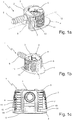
- Fign. 1a-1c
- den erfindungsgemäßen Spreizverbinder in zwei perspektivischen Ansichten (
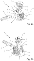
Fign. 1a, 1b ) und in einer Seitenansicht (Fig. 1c ); - Fign. 2a, 2b
- zwei unterschiedliche Explosionsdarstellungen des erfindungsgemäßen Spreizverbinders; und
- Fign. 3a, 3b
- einen Einbautopf des erfindungsgemäßen Spreizverbinders in einer perspektivischen Ansicht (
Fig. 3a ) und in einer Seitenansicht (Fig. 3b ). - Der in
Fign. 1 und2 gezeigte Spreizverbinder 1 dient zum Verbinden zweier Möbelteile (nicht gezeigt). InFign. 1a-1c ist der Spreizverbinder 1 im zusammengebauten Zustand und inFign. 2a, 2b in einer Explosionsdarstellung gezeigt. - Der Spreizverbinder 1 umfasst einen Einbautopf 2 (z.B. aus Kunststoff), der mit seinem Topfboden 3 voran in eine Topfbohrung des einen Möbelteils eingepresst wird, bis er andernends mit einem nach außen über die hohlzylindrische Topfwandung 3 vorstehenden Anschlagrand 4 an dem einen Möbelteil anliegt, sowie ein innerhalb des Einbautopfes 3 drehbar gelagertes Anzugselement 5 (z.B. Zinkdruckguss), das über eine topfbodenseitige Öffnung 6 in den Einbautopf 2 rastend eingesetzt ist.
- Der Einbautopf 2 weist in seiner hohlzylindrischen Topfwandung 7 eine bis in den Anschlagrand 4 hinein offene Wandöffnung 8 auf, durch die ein Spannbolzen 9 des anderen Möbelteils hindurch- und in das Anzugselement 5 eingreift. Das Anzugselement 5 hat eine innere Exzenterfläche 10, um durch Drehen des Anzugelements 5 den Kopf des Spannbolzens 9 zu hintergreifen und dadurch den Spannbolzen 9 anzuziehen. Das Anzugselement 5 weist auf seiner dem Topfboden 3 abgewandten Seite eine Werkzeugaufnahme (nicht gezeigt), z.B. einen Kreuzschlitz auf, um bei eingepresstem Spreizverbinder 1 das Anzugselement 5 drehen zu können.
- In der hohlzylindrischen Topfwandung 7 sind zwei einander bezüglich des Anzugselements 5 gegenüberliegende Spreiziaschen 11 freigeschnitten, die an dem dem Topfboden 3 zugewandten Endbereich der hohlzylindrischen Topfwandung 7 - beabstandet zum Topfboden 3 - an der hohlzylindrischen Topfwandung 7 angebunden und jeweils um eine tangential zur hohlzylindrischen Topfwandung 7 und parallel zum Topfboden 3 verlaufende Achse 12 schwenkbar sind. Die beiden Spreizlaschen 11 erstrecken sich jeweils mit ihrem freien Laschenende 13 in Richtung auf den Anschlagrand 4 und sind von diesem axial beabstandet, bevorzugt um ca. 1 bis 3 mm. Dadurch bilden die dem Anschlagrand 4 zugewandten Kanten der freien Laschenenden 13 jeweils einen entgegen der Einpressrichtung des Einbautopfes wirkenden Hinterschnitt, der sich in das Holzmaterial einer Bohrungswandung eingräbt und für eine zusätzliche Verankerung sorgt.
- Wie in
Fign. 3a, 3b gezeigt, sind die beiden Spreizlaschen 11 durch einen U-förmigen Schnitt 14 freigeschnitten, wodurch die hohlzylindrische Topfwandung 3 zwischen dem freien Laschenende 11 und dem Anschlagrand 4 ausgespart ist. - Das Anzugselement 5 weist zwei äußere Exzenterflächen 15 auf zum Aufspreizen der beiden Spreizlaschen 11, um durch Drehen des Anzugelements 5 die beiden Spreizlaschen 11 aus der hohlzylindrischen Topfwandung 7 heraus nach außen abzuspreizen.
Claims (8)
- Spreizverbinder (1) zum Verbinden zweier Möbelteile, umfassend einen Einbautopf (2), der mit seinem Topfboden (3) voran in eine Topfbohrung des einen Möbelteils einpressbar ist und dessen hohlzylindrische Topfwandung (7) eine Wandöffnung (8) und mindestens eine in der hohlzylindrischen Topfwandung (7) freigeschnittene, um eine tangential zur hohlzylindrischen Topfwandung (7) verlaufende Achse (12) schwenkbare Spreizlasche (11) aufweist, sowie ein innerhalb des Einbautopfes (7) drehbar gelagertes Anzugselement (5) zum Anziehen eines durch die Wandöffnung (8) hindurchgreifenden Spannbolzens (9) des anderen Möbelteils, wobei das Anzugselement (5) eine äußere Exzenterfläche (15) zum Aufspreizen der mindestens einen Spreizlasche (11) aufweist,
dadurch gekennzeichnet,
dass sich die mindestens eine Spreizlasche (11) mit ihrem freien Laschenende (13) in axialer Richtung fort von dem Topfboden (3) erstreckt. - Spreizverbinder nach Anspruch 1, dadurch gekennzeichnet, dass die mindestens eine Spreizlasche (11) an dem dem Topfboden (3) zugewandten Endbereich der hohlzylindrischen Topfwandung (7) angebunden ist.
- Spreizverbinder nach Anspruch 1 oder 2, dadurch gekennzeichnet, dass die mindestens eine Spreizlasche (11) axial beabstandet zum Topfboden (3) an der hohlzylindrischen Topfwandung (7) angebunden ist.
- Spreizverbinder nach einem der vorhergehenden Ansprüche, dadurch gekennzeichnet, dass das freie Laschenende (13) der mindestens einen Spreizlasche (11) von einem nach außen über die hohlzylindrische Topfwandung (3) vorstehenden Anschlagrand (4) des Einbautopfes (2) axial beabstandet ist.
- Spreizverbinder nach Anspruch 4, dadurch gekennzeichnet, dass das freie Laschenende (13) der mindestens einen Spreizlasche (11) von dem Anschlagrand (4) um mindestens 1mm, vorzugsweise um mindestens 2mm, beabstandet ist.
- Spreizverbinder nach Anspruch 4 oder 5, dadurch gekennzeichnet, dass die hohlzylindrische Topfwandung (7) zwischen dem freien Laschenende (13) und dem Anschlagrand (4) ausgespart ist.
- Spreizverbinder nach einem der vorhergehenden Ansprüche, dadurch gekennzeichnet, dass die mindestens eine Spreizlasche (11) in der hohlzylindrischen Topfwandung (7) durch einen U-förmigen Schnitt (14) freigeschnitten ist.
- Spreizverbinder nach einem der vorhergehenden Ansprüche, dadurch gekennzeichnet, dass die hohlzylindrische Topfwandung (7) mindestens zwei einander bezüglich des Anzugselements (5) gegenüberliegende freigeschnittene Spreizlaschen (11) aufweist.
Priority Applications (1)
| Application Number | Priority Date | Filing Date | Title |
|---|---|---|---|
| PL14156622T PL2808566T3 (pl) | 2013-05-31 | 2014-02-25 | Łącznik rozporowy |
Applications Claiming Priority (1)
| Application Number | Priority Date | Filing Date | Title |
|---|---|---|---|
| DE202013102366U DE202013102366U1 (de) | 2013-05-31 | 2013-05-31 | Spreizverbinder |
Publications (2)
| Publication Number | Publication Date |
|---|---|
| EP2808566A1 EP2808566A1 (de) | 2014-12-03 |
| EP2808566B1 true EP2808566B1 (de) | 2017-06-28 |
Family
ID=48784288
Family Applications (1)
| Application Number | Title | Priority Date | Filing Date |
|---|---|---|---|
| EP14156622.4A Active EP2808566B1 (de) | 2013-05-31 | 2014-02-25 | Spreizverbinder |
Country Status (5)
| Country | Link |
|---|---|
| US (1) | US10161432B2 (de) |
| EP (1) | EP2808566B1 (de) |
| DE (1) | DE202013102366U1 (de) |
| ES (1) | ES2642007T3 (de) |
| PL (1) | PL2808566T3 (de) |
Families Citing this family (13)
| Publication number | Priority date | Publication date | Assignee | Title |
|---|---|---|---|---|
| DE202015103874U1 (de) | 2015-07-23 | 2016-10-25 | Grass Gmbh | Vorrichtung zum Verbinden zweier Möbelteile |
| DE102016103248B4 (de) * | 2016-02-24 | 2022-04-14 | Elepart Plastics Gmbh | Exzentereinheit, Federklammer, Verbinder und Verfahren hierzu |
| WO2018149517A1 (en) * | 2017-02-15 | 2018-08-23 | Husqvarna Ab | Locking element for detachably coupling a work implement to a handle of a tool |
| US10669773B2 (en) * | 2017-09-19 | 2020-06-02 | Richard Paul Grube | Adjustable assembly double stabilized screen door |
| IT201800010832A1 (it) * | 2018-12-05 | 2020-06-05 | Sea Soc Europea Autocaravan S P A | Sistema di fissaggio per mobili |
| AT522092B1 (de) * | 2018-12-20 | 2020-08-15 | Blum Gmbh Julius | Möbelantrieb |
| DE102019127895A1 (de) * | 2019-10-16 | 2021-04-22 | Grass Gmbh | Dübelvorrichtung |
| EP3872356B1 (de) * | 2020-02-27 | 2022-04-27 | Franz-Josef Langhorst | Möbelteilverbindungsanordnung |
| EP3933146B1 (de) * | 2020-07-01 | 2025-09-10 | Siemens Gamesa Renewable Energy A/S | Bolzensystem für verbindungsflansche |
| US12516691B2 (en) | 2021-05-25 | 2026-01-06 | Textron Innovations Inc. | Fastening system with edgemount insert |
| MX2021011602A (es) * | 2021-09-23 | 2023-03-24 | Eduardo Calderon Abad | Tejido plastico de ensamble rotativo. |
| CN116557392A (zh) * | 2022-01-27 | 2023-08-08 | 广东卡诺亚家居股份有限公司 | 三合一层托板固层连接件 |
| CN115263880B (zh) * | 2022-06-16 | 2023-05-23 | 广东卡诺亚家居股份有限公司 | 一种三合一层托板固层连接件 |
Family Cites Families (12)
| Publication number | Priority date | Publication date | Assignee | Title |
|---|---|---|---|---|
| DE6916620U (de) * | 1969-04-24 | 1969-10-02 | Poschinger Whb Anbaumoebel | Beschlag zum verbinden zweier aufeinander senkrecht stehender regalteile, vorzugsweise zweier holzbretter |
| FR2333991A1 (fr) * | 1975-12-05 | 1977-07-01 | Aubier Cuny Sa | Dispositif pour l'assemblage de deux panneaux, en particulier de deux panneaux appartenant a un meuble |
| DE2610200C3 (de) * | 1976-03-11 | 1980-01-31 | Richard Heinze Gmbh & Co Kg, 4900 Herford | Beschlag zum lösbaren Verbinden zweier Bauteile, insbesondere von plattenförmigen Bauteilen für Möbel |
| US4353663A (en) * | 1980-06-03 | 1982-10-12 | Conroy, Inc. | Detachable connector for structural members and method of installation |
| IT1169586B (it) * | 1983-10-18 | 1987-06-03 | Giovannetti F | Dispositivo di fissaggio per unire tra loro pannelli in modo sbloccabile |
| GB2301412B (en) * | 1995-05-31 | 1999-03-10 | Titus Int Plc | A housing for joint forming devices |
| ES2221492B1 (es) * | 1998-12-09 | 2005-07-16 | Miguel Angel Rioja Calvo | Dispositivo perfeccionado para ensamble de paneles de muebles. |
| DE20219178U1 (de) * | 2002-12-11 | 2003-03-06 | Hettich-Heinze GmbH & Co. KG, 32139 Spenge | Verbindungsbeschlag zum Verbinden zweier Möbelteile |
| ITPN20030037U1 (it) * | 2003-11-14 | 2005-05-15 | Livenza Ferramenta Srl | Dispositivo reggi-piano perfezionato |
| DE202007009771U1 (de) * | 2007-07-13 | 2007-09-20 | Häfele GmbH & Co KG | Verbindungsbeschlag für Platten, insbesondere für Tablare |
| WO2009146503A1 (en) * | 2008-06-04 | 2009-12-10 | Milan Pilja | Connecting fitting |
| US20100202852A1 (en) * | 2009-02-09 | 2010-08-12 | Krause Steven T | No-tools panel coupler and insert |
-
2013
- 2013-05-31 DE DE202013102366U patent/DE202013102366U1/de not_active Expired - Lifetime
-
2014
- 2014-02-25 EP EP14156622.4A patent/EP2808566B1/de active Active
- 2014-02-25 PL PL14156622T patent/PL2808566T3/pl unknown
- 2014-02-25 ES ES14156622.4T patent/ES2642007T3/es active Active
- 2014-04-21 US US14/257,346 patent/US10161432B2/en active Active
Also Published As
| Publication number | Publication date |
|---|---|
| PL2808566T3 (pl) | 2018-01-31 |
| EP2808566A1 (de) | 2014-12-03 |
| DE202013102366U1 (de) | 2013-06-12 |
| US20140356093A1 (en) | 2014-12-04 |
| ES2642007T3 (es) | 2017-11-14 |
| US10161432B2 (en) | 2018-12-25 |
Similar Documents
| Publication | Publication Date | Title |
|---|---|---|
| EP2808566A1 (de) | Spreizverbinder | |
| DE4124727C2 (de) | Befestigungselement mit einer dübelartigen Buchse | |
| DE19828059C2 (de) | Anschlußarmatur mit einem durch Schlitze in Haltezungen aufgeteilten Befestigungsvorsprung | |
| DE2702643B2 (de) | Beschlag zum lösbaren Verbinden zweier senkrecht aufeinanderstoßender Bauteile, insbesondere Möbelteile | |
| WO2008011950A1 (de) | Vorrichtung zum befestigen eines anbauteiles und eines trägerteiles in einem abstand voneinander | |
| WO2011120609A1 (de) | Kabelverschraubung mit klemmeinrichtung für eine armierung des kabels | |
| EP1277971A1 (de) | Unverlierbarer Spreizanker | |
| DE102013215955A1 (de) | Wanddurchführungselement für eine Fluidleitung und Wanddurchführung | |
| DE10134605A1 (de) | Spreizdübel | |
| DE102011002163A1 (de) | Spreizdübel | |
| EP2715200B1 (de) | Spielfreie steckverbindung für rohr- oder schlauchleitungen | |
| EP2867966A2 (de) | Kabelverschraubung für ein abgeschirmtes kabel mit einer kontakteinrichtung | |
| AT519920B1 (de) | Befestigungsvorrichtung | |
| EP4018100B1 (de) | Verbindungsbeschlag | |
| DE102011111064A1 (de) | Anordnung zur, insbesondere distanzierten, Befestigung zumindest einer Dammstoffplatte an einem Gebäude | |
| WO2017108730A1 (de) | Zahnscheibe mit mehrstegigen haltezähnen | |
| DE202006013243U1 (de) | Stecker | |
| EP4019819B1 (de) | Vorrichtung mit zwei bauteilen, insbesondere schelle mit einem schellenring | |
| DE102019213029B4 (de) | Schraubenmuttervorrichtung | |
| EP2612040B1 (de) | Spreizdübel | |
| EP3180521A1 (de) | Clip-element, verfahren zum herstellen einer bauteilverbindung sowie bauteilverbindung | |
| DE19647209C2 (de) | Befestigungsvorrichtung aus Kunststoff | |
| DE19717116B4 (de) | Drehlager | |
| EP2020513B1 (de) | Beschlag zum Verbinden zweier Möbelplatten | |
| DE102006057206A1 (de) | Mit einem Stahlregler versehenes sanitäres Wasserventil |
Legal Events
| Date | Code | Title | Description |
|---|---|---|---|
| PUAI | Public reference made under article 153(3) epc to a published international application that has entered the european phase |
Free format text: ORIGINAL CODE: 0009012 |
|
| 17P | Request for examination filed |
Effective date: 20140225 |
|
| AK | Designated contracting states |
Kind code of ref document: A1 Designated state(s): AL AT BE BG CH CY CZ DE DK EE ES FI FR GB GR HR HU IE IS IT LI LT LU LV MC MK MT NL NO PL PT RO RS SE SI SK SM TR |
|
| AX | Request for extension of the european patent |
Extension state: BA ME |
|
| R17P | Request for examination filed (corrected) |
Effective date: 20150203 |
|
| RBV | Designated contracting states (corrected) |
Designated state(s): AL AT BE BG CH CY CZ DE DK EE ES FI FR GB GR HR HU IE IS IT LI LT LU LV MC MK MT NL NO PL PT RO RS SE SI SK SM TR |
|
| GRAP | Despatch of communication of intention to grant a patent |
Free format text: ORIGINAL CODE: EPIDOSNIGR1 |
|
| INTG | Intention to grant announced |
Effective date: 20161209 |
|
| GRAS | Grant fee paid |
Free format text: ORIGINAL CODE: EPIDOSNIGR3 |
|
| GRAA | (expected) grant |
Free format text: ORIGINAL CODE: 0009210 |
|
| AK | Designated contracting states |
Kind code of ref document: B1 Designated state(s): AL AT BE BG CH CY CZ DE DK EE ES FI FR GB GR HR HU IE IS IT LI LT LU LV MC MK MT NL NO PL PT RO RS SE SI SK SM TR |
|
| REG | Reference to a national code |
Ref country code: GB Ref legal event code: FG4D Free format text: NOT ENGLISH |
|
| REG | Reference to a national code |
Ref country code: CH Ref legal event code: EP |
|
| REG | Reference to a national code |
Ref country code: AT Ref legal event code: REF Ref document number: 905124 Country of ref document: AT Kind code of ref document: T Effective date: 20170715 |
|
| REG | Reference to a national code |
Ref country code: IE Ref legal event code: FG4D Free format text: LANGUAGE OF EP DOCUMENT: GERMAN |
|
| REG | Reference to a national code |
Ref country code: DE Ref legal event code: R096 Ref document number: 502014004381 Country of ref document: DE |
|
| REG | Reference to a national code |
Ref country code: NL Ref legal event code: FP |
|
| REG | Reference to a national code |
Ref country code: SE Ref legal event code: TRGR |
|
| PG25 | Lapsed in a contracting state [announced via postgrant information from national office to epo] |
Ref country code: LT Free format text: LAPSE BECAUSE OF FAILURE TO SUBMIT A TRANSLATION OF THE DESCRIPTION OR TO PAY THE FEE WITHIN THE PRESCRIBED TIME-LIMIT Effective date: 20170628 Ref country code: NO Free format text: LAPSE BECAUSE OF FAILURE TO SUBMIT A TRANSLATION OF THE DESCRIPTION OR TO PAY THE FEE WITHIN THE PRESCRIBED TIME-LIMIT Effective date: 20170928 Ref country code: FI Free format text: LAPSE BECAUSE OF FAILURE TO SUBMIT A TRANSLATION OF THE DESCRIPTION OR TO PAY THE FEE WITHIN THE PRESCRIBED TIME-LIMIT Effective date: 20170628 Ref country code: GR Free format text: LAPSE BECAUSE OF FAILURE TO SUBMIT A TRANSLATION OF THE DESCRIPTION OR TO PAY THE FEE WITHIN THE PRESCRIBED TIME-LIMIT Effective date: 20170929 Ref country code: HR Free format text: LAPSE BECAUSE OF FAILURE TO SUBMIT A TRANSLATION OF THE DESCRIPTION OR TO PAY THE FEE WITHIN THE PRESCRIBED TIME-LIMIT Effective date: 20170628 |
|
| REG | Reference to a national code |
Ref country code: LT Ref legal event code: MG4D |
|
| REG | Reference to a national code |
Ref country code: ES Ref legal event code: FG2A Ref document number: 2642007 Country of ref document: ES Kind code of ref document: T3 Effective date: 20171114 |
|
| PG25 | Lapsed in a contracting state [announced via postgrant information from national office to epo] |
Ref country code: LV Free format text: LAPSE BECAUSE OF FAILURE TO SUBMIT A TRANSLATION OF THE DESCRIPTION OR TO PAY THE FEE WITHIN THE PRESCRIBED TIME-LIMIT Effective date: 20170628 Ref country code: BG Free format text: LAPSE BECAUSE OF FAILURE TO SUBMIT A TRANSLATION OF THE DESCRIPTION OR TO PAY THE FEE WITHIN THE PRESCRIBED TIME-LIMIT Effective date: 20170928 Ref country code: RS Free format text: LAPSE BECAUSE OF FAILURE TO SUBMIT A TRANSLATION OF THE DESCRIPTION OR TO PAY THE FEE WITHIN THE PRESCRIBED TIME-LIMIT Effective date: 20170628 |
|
| PG25 | Lapsed in a contracting state [announced via postgrant information from national office to epo] |
Ref country code: EE Free format text: LAPSE BECAUSE OF FAILURE TO SUBMIT A TRANSLATION OF THE DESCRIPTION OR TO PAY THE FEE WITHIN THE PRESCRIBED TIME-LIMIT Effective date: 20170628 Ref country code: SK Free format text: LAPSE BECAUSE OF FAILURE TO SUBMIT A TRANSLATION OF THE DESCRIPTION OR TO PAY THE FEE WITHIN THE PRESCRIBED TIME-LIMIT Effective date: 20170628 Ref country code: RO Free format text: LAPSE BECAUSE OF FAILURE TO SUBMIT A TRANSLATION OF THE DESCRIPTION OR TO PAY THE FEE WITHIN THE PRESCRIBED TIME-LIMIT Effective date: 20170628 Ref country code: CZ Free format text: LAPSE BECAUSE OF FAILURE TO SUBMIT A TRANSLATION OF THE DESCRIPTION OR TO PAY THE FEE WITHIN THE PRESCRIBED TIME-LIMIT Effective date: 20170628 |
|
| REG | Reference to a national code |
Ref country code: FR Ref legal event code: PLFP Year of fee payment: 5 |
|
| PG25 | Lapsed in a contracting state [announced via postgrant information from national office to epo] |
Ref country code: IS Free format text: LAPSE BECAUSE OF FAILURE TO SUBMIT A TRANSLATION OF THE DESCRIPTION OR TO PAY THE FEE WITHIN THE PRESCRIBED TIME-LIMIT Effective date: 20171028 Ref country code: SM Free format text: LAPSE BECAUSE OF FAILURE TO SUBMIT A TRANSLATION OF THE DESCRIPTION OR TO PAY THE FEE WITHIN THE PRESCRIBED TIME-LIMIT Effective date: 20170628 |
|
| REG | Reference to a national code |
Ref country code: DE Ref legal event code: R097 Ref document number: 502014004381 Country of ref document: DE |
|
| PG25 | Lapsed in a contracting state [announced via postgrant information from national office to epo] |
Ref country code: DK Free format text: LAPSE BECAUSE OF FAILURE TO SUBMIT A TRANSLATION OF THE DESCRIPTION OR TO PAY THE FEE WITHIN THE PRESCRIBED TIME-LIMIT Effective date: 20170628 |
|
| PLBE | No opposition filed within time limit |
Free format text: ORIGINAL CODE: 0009261 |
|
| STAA | Information on the status of an ep patent application or granted ep patent |
Free format text: STATUS: NO OPPOSITION FILED WITHIN TIME LIMIT |
|
| 26N | No opposition filed |
Effective date: 20180329 |
|
| PG25 | Lapsed in a contracting state [announced via postgrant information from national office to epo] |
Ref country code: SI Free format text: LAPSE BECAUSE OF FAILURE TO SUBMIT A TRANSLATION OF THE DESCRIPTION OR TO PAY THE FEE WITHIN THE PRESCRIBED TIME-LIMIT Effective date: 20170628 |
|
| REG | Reference to a national code |
Ref country code: CH Ref legal event code: PL |
|
| PG25 | Lapsed in a contracting state [announced via postgrant information from national office to epo] |
Ref country code: MC Free format text: LAPSE BECAUSE OF FAILURE TO SUBMIT A TRANSLATION OF THE DESCRIPTION OR TO PAY THE FEE WITHIN THE PRESCRIBED TIME-LIMIT Effective date: 20170628 Ref country code: MT Free format text: LAPSE BECAUSE OF FAILURE TO SUBMIT A TRANSLATION OF THE DESCRIPTION OR TO PAY THE FEE WITHIN THE PRESCRIBED TIME-LIMIT Effective date: 20170628 |
|
| PG25 | Lapsed in a contracting state [announced via postgrant information from national office to epo] |
Ref country code: CH Free format text: LAPSE BECAUSE OF NON-PAYMENT OF DUE FEES Effective date: 20180228 Ref country code: LI Free format text: LAPSE BECAUSE OF NON-PAYMENT OF DUE FEES Effective date: 20180228 Ref country code: LU Free format text: LAPSE BECAUSE OF NON-PAYMENT OF DUE FEES Effective date: 20180225 |
|
| REG | Reference to a national code |
Ref country code: IE Ref legal event code: MM4A |
|
| PG25 | Lapsed in a contracting state [announced via postgrant information from national office to epo] |
Ref country code: IE Free format text: LAPSE BECAUSE OF NON-PAYMENT OF DUE FEES Effective date: 20180225 |
|
| REG | Reference to a national code |
Ref country code: AT Ref legal event code: MM01 Ref document number: 905124 Country of ref document: AT Kind code of ref document: T Effective date: 20190225 |
|
| PG25 | Lapsed in a contracting state [announced via postgrant information from national office to epo] |
Ref country code: AT Free format text: LAPSE BECAUSE OF NON-PAYMENT OF DUE FEES Effective date: 20190225 |
|
| PG25 | Lapsed in a contracting state [announced via postgrant information from national office to epo] |
Ref country code: PT Free format text: LAPSE BECAUSE OF FAILURE TO SUBMIT A TRANSLATION OF THE DESCRIPTION OR TO PAY THE FEE WITHIN THE PRESCRIBED TIME-LIMIT Effective date: 20170628 Ref country code: HU Free format text: LAPSE BECAUSE OF FAILURE TO SUBMIT A TRANSLATION OF THE DESCRIPTION OR TO PAY THE FEE WITHIN THE PRESCRIBED TIME-LIMIT; INVALID AB INITIO Effective date: 20140225 |
|
| PG25 | Lapsed in a contracting state [announced via postgrant information from national office to epo] |
Ref country code: MK Free format text: LAPSE BECAUSE OF NON-PAYMENT OF DUE FEES Effective date: 20170628 Ref country code: CY Free format text: LAPSE BECAUSE OF FAILURE TO SUBMIT A TRANSLATION OF THE DESCRIPTION OR TO PAY THE FEE WITHIN THE PRESCRIBED TIME-LIMIT Effective date: 20170628 |
|
| PG25 | Lapsed in a contracting state [announced via postgrant information from national office to epo] |
Ref country code: AL Free format text: LAPSE BECAUSE OF FAILURE TO SUBMIT A TRANSLATION OF THE DESCRIPTION OR TO PAY THE FEE WITHIN THE PRESCRIBED TIME-LIMIT Effective date: 20170628 |
|
| PGFP | Annual fee paid to national office [announced via postgrant information from national office to epo] |
Ref country code: NL Payment date: 20230220 Year of fee payment: 10 |
|
| PGFP | Annual fee paid to national office [announced via postgrant information from national office to epo] |
Ref country code: FR Payment date: 20230217 Year of fee payment: 10 Ref country code: ES Payment date: 20230317 Year of fee payment: 10 |
|
| PGFP | Annual fee paid to national office [announced via postgrant information from national office to epo] |
Ref country code: TR Payment date: 20230223 Year of fee payment: 10 Ref country code: SE Payment date: 20230220 Year of fee payment: 10 Ref country code: BE Payment date: 20230220 Year of fee payment: 10 |
|
| P01 | Opt-out of the competence of the unified patent court (upc) registered |
Effective date: 20230630 |
|
| PGFP | Annual fee paid to national office [announced via postgrant information from national office to epo] |
Ref country code: GB Payment date: 20240222 Year of fee payment: 11 |
|
| REG | Reference to a national code |
Ref country code: SE Ref legal event code: EUG |
|
| REG | Reference to a national code |
Ref country code: NL Ref legal event code: MM Effective date: 20240301 |
|
| PG25 | Lapsed in a contracting state [announced via postgrant information from national office to epo] |
Ref country code: NL Free format text: LAPSE BECAUSE OF NON-PAYMENT OF DUE FEES Effective date: 20240301 |
|
| PG25 | Lapsed in a contracting state [announced via postgrant information from national office to epo] |
Ref country code: NL Free format text: LAPSE BECAUSE OF NON-PAYMENT OF DUE FEES Effective date: 20240301 |
|
| REG | Reference to a national code |
Ref country code: BE Ref legal event code: MM Effective date: 20240229 |
|
| PG25 | Lapsed in a contracting state [announced via postgrant information from national office to epo] |
Ref country code: BE Free format text: LAPSE BECAUSE OF NON-PAYMENT OF DUE FEES Effective date: 20240229 |
|
| PG25 | Lapsed in a contracting state [announced via postgrant information from national office to epo] |
Ref country code: FR Free format text: LAPSE BECAUSE OF NON-PAYMENT OF DUE FEES Effective date: 20240229 |
|
| PG25 | Lapsed in a contracting state [announced via postgrant information from national office to epo] |
Ref country code: FR Free format text: LAPSE BECAUSE OF NON-PAYMENT OF DUE FEES Effective date: 20240229 Ref country code: BE Free format text: LAPSE BECAUSE OF NON-PAYMENT OF DUE FEES Effective date: 20240229 |
|
| REG | Reference to a national code |
Ref country code: ES Ref legal event code: FD2A Effective date: 20250402 |
|
| PG25 | Lapsed in a contracting state [announced via postgrant information from national office to epo] |
Ref country code: ES Free format text: LAPSE BECAUSE OF NON-PAYMENT OF DUE FEES Effective date: 20240226 |
|
| PG25 | Lapsed in a contracting state [announced via postgrant information from national office to epo] |
Ref country code: SE Free format text: LAPSE BECAUSE OF NON-PAYMENT OF DUE FEES Effective date: 20240226 |
|
| GBPC | Gb: european patent ceased through non-payment of renewal fee |
Effective date: 20250225 |
|
| PG25 | Lapsed in a contracting state [announced via postgrant information from national office to epo] |
Ref country code: GB Free format text: LAPSE BECAUSE OF NON-PAYMENT OF DUE FEES Effective date: 20250225 |
|
| PGFP | Annual fee paid to national office [announced via postgrant information from national office to epo] |
Ref country code: DE Payment date: 20260224 Year of fee payment: 13 |
|
| PGFP | Annual fee paid to national office [announced via postgrant information from national office to epo] |
Ref country code: IT Payment date: 20260227 Year of fee payment: 13 |
|
| PGFP | Annual fee paid to national office [announced via postgrant information from national office to epo] |
Ref country code: PL Payment date: 20260122 Year of fee payment: 13 |