EP2808486B1 - Wuchtkörper für eine Laufschaufelanordnung - Google Patents
Wuchtkörper für eine Laufschaufelanordnung Download PDFInfo
- Publication number
- EP2808486B1 EP2808486B1 EP13169289.9A EP13169289A EP2808486B1 EP 2808486 B1 EP2808486 B1 EP 2808486B1 EP 13169289 A EP13169289 A EP 13169289A EP 2808486 B1 EP2808486 B1 EP 2808486B1
- Authority
- EP
- European Patent Office
- Prior art keywords
- balancing body
- rotor blade
- ring
- blade arrangement
- stop
- Prior art date
- Legal status (The legal status is an assumption and is not a legal conclusion. Google has not performed a legal analysis and makes no representation as to the accuracy of the status listed.)
- Not-in-force
Links
Images
Classifications
-
- F—MECHANICAL ENGINEERING; LIGHTING; HEATING; WEAPONS; BLASTING
- F01—MACHINES OR ENGINES IN GENERAL; ENGINE PLANTS IN GENERAL; STEAM ENGINES
- F01D—NON-POSITIVE DISPLACEMENT MACHINES OR ENGINES, e.g. STEAM TURBINES
- F01D5/00—Blades; Blade-carrying members; Heating, heat-insulating, cooling or antivibration means on the blades or the members
- F01D5/02—Blade-carrying members, e.g. rotors
- F01D5/027—Arrangements for balancing
-
- F—MECHANICAL ENGINEERING; LIGHTING; HEATING; WEAPONS; BLASTING
- F01—MACHINES OR ENGINES IN GENERAL; ENGINE PLANTS IN GENERAL; STEAM ENGINES
- F01D—NON-POSITIVE DISPLACEMENT MACHINES OR ENGINES, e.g. STEAM TURBINES
- F01D25/00—Component parts, details, or accessories, not provided for in, or of interest apart from, other groups
- F01D25/28—Supporting or mounting arrangements, e.g. for turbine casing
-
- F—MECHANICAL ENGINEERING; LIGHTING; HEATING; WEAPONS; BLASTING
- F01—MACHINES OR ENGINES IN GENERAL; ENGINE PLANTS IN GENERAL; STEAM ENGINES
- F01D—NON-POSITIVE DISPLACEMENT MACHINES OR ENGINES, e.g. STEAM TURBINES
- F01D5/00—Blades; Blade-carrying members; Heating, heat-insulating, cooling or antivibration means on the blades or the members
- F01D5/12—Blades
- F01D5/22—Blade-to-blade connections, e.g. for damping vibrations
- F01D5/225—Blade-to-blade connections, e.g. for damping vibrations by shrouding
-
- F—MECHANICAL ENGINEERING; LIGHTING; HEATING; WEAPONS; BLASTING
- F16—ENGINEERING ELEMENTS AND UNITS; GENERAL MEASURES FOR PRODUCING AND MAINTAINING EFFECTIVE FUNCTIONING OF MACHINES OR INSTALLATIONS; THERMAL INSULATION IN GENERAL
- F16F—SPRINGS; SHOCK-ABSORBERS; MEANS FOR DAMPING VIBRATION
- F16F15/00—Suppression of vibrations in systems; Means or arrangements for avoiding or reducing out-of-balance forces, e.g. due to motion
- F16F15/32—Correcting- or balancing-weights or equivalent means for balancing rotating bodies, e.g. vehicle wheels
-
- F—MECHANICAL ENGINEERING; LIGHTING; HEATING; WEAPONS; BLASTING
- F05—INDEXING SCHEMES RELATING TO ENGINES OR PUMPS IN VARIOUS SUBCLASSES OF CLASSES F01-F04
- F05D—INDEXING SCHEME FOR ASPECTS RELATING TO NON-POSITIVE-DISPLACEMENT MACHINES OR ENGINES, GAS-TURBINES OR JET-PROPULSION PLANTS
- F05D2230/00—Manufacture
- F05D2230/60—Assembly methods
-
- F—MECHANICAL ENGINEERING; LIGHTING; HEATING; WEAPONS; BLASTING
- F05—INDEXING SCHEMES RELATING TO ENGINES OR PUMPS IN VARIOUS SUBCLASSES OF CLASSES F01-F04
- F05D—INDEXING SCHEME FOR ASPECTS RELATING TO NON-POSITIVE-DISPLACEMENT MACHINES OR ENGINES, GAS-TURBINES OR JET-PROPULSION PLANTS
- F05D2260/00—Function
- F05D2260/15—Load balancing
-
- Y—GENERAL TAGGING OF NEW TECHNOLOGICAL DEVELOPMENTS; GENERAL TAGGING OF CROSS-SECTIONAL TECHNOLOGIES SPANNING OVER SEVERAL SECTIONS OF THE IPC; TECHNICAL SUBJECTS COVERED BY FORMER USPC CROSS-REFERENCE ART COLLECTIONS [XRACs] AND DIGESTS
- Y10—TECHNICAL SUBJECTS COVERED BY FORMER USPC
- Y10T—TECHNICAL SUBJECTS COVERED BY FORMER US CLASSIFICATION
- Y10T29/00—Metal working
- Y10T29/49—Method of mechanical manufacture
- Y10T29/49229—Prime mover or fluid pump making
- Y10T29/49236—Fluid pump or compressor making
- Y10T29/49245—Vane type or other rotary, e.g., fan
-
- Y—GENERAL TAGGING OF NEW TECHNOLOGICAL DEVELOPMENTS; GENERAL TAGGING OF CROSS-SECTIONAL TECHNOLOGIES SPANNING OVER SEVERAL SECTIONS OF THE IPC; TECHNICAL SUBJECTS COVERED BY FORMER USPC CROSS-REFERENCE ART COLLECTIONS [XRACs] AND DIGESTS
- Y10—TECHNICAL SUBJECTS COVERED BY FORMER USPC
- Y10T—TECHNICAL SUBJECTS COVERED BY FORMER US CLASSIFICATION
- Y10T29/00—Metal working
- Y10T29/49—Method of mechanical manufacture
- Y10T29/49316—Impeller making
- Y10T29/4932—Turbomachine making
Definitions
- the present invention relates to a balancing body for attachment to a ring of a blade assembly, a blade assembly of a compressor or turbine stage of a gas turbine having such a balancing body and a method for setting or releasing such balancing body of the blade assembly.
- An object of an embodiment of the present invention is to improve a gas turbine.
- One aspect of the present invention relates to a blade assembly of a compressor or turbine stage or for a compressor or turbine stage of a gas turbine and a gas turbine with such a compressor or turbine stage or blade assembly.
- the blade assembly includes a plurality of blade blades adjacent or distributed in a circumferential direction. These may be releasably or permanently attached to a rotor of the turbine (ntyp), in particular be formed integrally therewith.
- the blade assembly includes a ring defining a flow channel for a working fluid of the gas turbine.
- the ring is a one-piece or multi-part radially outer or outer ring or a so-called outer shroud, which may be connected to one or more blades.
- the ring may be a one-piece or multi-piece radially inner or inner ring or a so-called blade platform, which may be connected to one or more blade blades.
- One or more balancing bodies are or are arranged, preferably at one or more predetermined circumferential positions, on the ring in each case between two blade leaves of the rotor blade arrangement which are adjacent in a circumferential direction.
- a balancing body engages in a circumferential direction a parting line between two adjacent ring parts.
- the mass or mass distribution of a balancing body can be represented in one embodiment by varying one or more recesses and / or by varying a wall thickness of the balancing body.
- a balancing body from the adjacent blades, between which it is disposed spaced apart in a circumferential direction and positively defines by one or in opposite directions by two axial paragraphs of the ring. This can be reduced by balancing body in one embodiment, the risk of deterioration of airfoils. Additionally or alternatively, the assembly and / or disassembly of balancing bodies, in particular in situ on the arranged in the gas turbine rotor blade assembly, preferably through a thrust nozzle of the gas turbine through, can be improved.
- a balancer for attachment to a ring of a blade assembly of a compressor or turbine stage of a gas turbine has a first stop for positively locking the balancer in a circumferential direction on a first axial shoulder of the ring.
- at least one limitation of a clearance in the circumferential direction in a further development, is a rotationally fixed one or - understood at least substantially - backlash-free attachment.
- opposite circumferential direction or in the opposite direction to the first stop-paragraph pair of the balancing body can be fixed in a form-fitting manner by a second stop of the balancing body to a second axial shoulder of the ring or be.
- the balancing body can also be fixed in the further circumferential direction by an airfoil of the rotor blade arrangement.
- the one circumferential direction may be opposite one direction of rotation of the gas turbine or this, the other, opposite circumferential direction may accordingly be opposite to the direction of rotation of the gas turbine or the direction of rotation.
- the first stop-paragraph pair may determine the balancing body in or against the direction of rotation, an opposing second stop-paragraph pair corresponding to opposite or in the direction of rotation.
- a stop and an axial shoulder are understood to mean, in particular, a surface, in particular an end surface, which extends, at least substantially, in the axial direction and in the radial direction, wherein the surface forms a right angle with the circumferential direction, at least substantially or may be chamfered against them in or against the direction of rotation.
- the end face may in one embodiment, at least substantially, have the wall thickness of the remaining ring or be formed as a material projection or - Wegten of the ring in the axial direction.
- the shoulder may extend axially away from an airfoil assembly of the blade assembly or may be formed as an axial material projection.
- a lever arm for limiting, in particular preventing, a rotation of the balancing body about a radial axis can advantageously be increased.
- the shoulder may extend axially toward the airfoil assembly of the blade assembly, or may be formed as an axial material recess opposite an axial outer edge of the ring.
- an axial projection of the ring can be reduced or avoided.
- the stop / heel pairs can set the balancer on or gegensinning in one or two opposite circumferential directions with play or limit its movement in the or the circumferential directions.
- the balancing body as stated above, also be - at least substantially free of play - be rotationally fixed or.
- the balancing body is clamped in the circumferential direction.
- at least one stop for the positive fixing of the balancing body in a circumferential direction can extend in the manner of a web or nose in the radial direction or can be made yielding in this circumferential direction.
- the balancing body in one embodiment has a first and an axially spaced second radial flange, which is connected by an axial web to the first radial flange.
- the two radial flanges overlap two axial end faces of the ring and fix it axially with or without play.
- the ring is or is axially clamped between the first and second radial flange.
- the first and / or second radial flange may be formed yielding.
- a radial flange can, seen in an embodiment in the direction of rotation, converge towards the ring, in particular beveled in the direction of rotation. In this way, in one embodiment, a snagging of the radial flange can be prevented.
- a stop for the positive fixing of the balancing body can be arranged in a circumferential direction on a radial flange, in particular be formed integrally therewith.
- the first and second stops can be arranged on circumferentially opposite sides of the same radial flange.
- the first stop is disposed on the first radial flange, the second stop on the circumferentially opposite side of the axially spaced second radial flange.
- the stop may, as stated above, web-like or nose-like extend in the radial direction. Accordingly, a web-like or nose-like stop can be formed by a radial cut in a radial flange. In this way, the web-like stopper can yield elastically or plastically in a circumferential direction into the recess.
- the balancing body in one embodiment has one or two, in particular axially spaced, undercuts which engage behind or under the ring.
- An undercut can be arranged in a development on a radial flange for positive fixing of the balancing body in the axial direction, in particular be formed integrally therewith.
- the undercut can be arranged on a stop for the positive fixing of the balancing body in a circumferential direction, in particular be formed integrally therewith. In this way, the definitions in the circumferential, radial and / or axial direction can be united.
- an undercut an axial shoulder of the ring behind or under which a stop of the balancing body determines this form-fitting in a circumferential direction.
- an undercut is formed by a folded flap, which also forms a stop for the positive fixing of the balancing body in the circumferential direction.
- At least one stop for the positive fixing of the balancing body in the circumferential direction in the axial direction to the blade blades of the blade assembly is elastically or plastically deformed and thus in or out of alignment, in particular in positive, preferably preloaded, contact, brought with the circumferentially opposite shoulder of the ring.
- an alignment or in-alignment is understood to mean, in particular, an arrangement such that the shoulder positively restricts a further movement of the stop in a circumferential direction, in particular that the shoulder contacts the stop and thus positively prevents a further movement of the stop in the circumferential direction.
- a stop of the balancing body in particular a part of a radial flange of the balancing body which is defined by an incision and defines the stop, can be elastically or plastically bent toward the ring or be aligned with an axial shoulder or To oppose this and set the balancing body so in the circumferential direction.
- a stop of the balancing body in particular one, preferably defined by an incision, part of a radial flange of the balancing body, which defines the stop, are elastically or plastically bent away from the ring or to be out of alignment with an axial shoulder his or this no longer be opposite, so that the balancing body is movable in the circumferential direction.
- the stop may have a predetermined bending line along which it can be elastically or plastically bent toward the ring or away from the ring.
- This bending line can be defined in particular by a thinning of the material and / or an incision which, in a development, can additionally form the abutment web or nose-like manner.
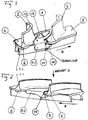
- Fig. 1, 2 show in perspective views ( Fig. 1 ) or in ( Fig. 2 ) a flow direction of a portion of an outer shroud of a blade assembly of a low-pressure turbine output stage of a gas turbine with a balancing body 1 according to an embodiment of the present invention.
- FIG. 1 In the views of Fig. 1, 2 are two blades 2, 3 of the blade assembly shown cut, which are each formed integrally with a shroud 4 and 5, which - together with other, not shown, shrouds form a ring in the form of a multi-part outer shroud.
- 3.1 (cf. Fig. 2 ) or 4.1 (cf. Fig. 1 ) is an input ( Fig. 2 ) or trailing edge ( Fig. 1 ) of an airfoil.
- Fig. 2 with III a plan view direction of the view of Fig. 3 indicated.
- Each shroud 4, 5 has on axially opposite end faces in each case an axial shoulder 6, which in the embodiment of Fig. 1-3 is formed by an axial material projection.
- the balancing body 1 is arranged between the two blade leaves 2, 3 of the blade arrangement, which are adjacent in a direction of rotation R, and are spaced therefrom in the direction of rotation R.
- first radial flange 8.1 see. Fig. 1
- second radially spaced therefrom second radial flange 8.2 see. Fig. 2
- a recess 12 is formed to adjust a predetermined mass or mass distribution of the balancing body.
- a first stop 11 of the balancing body is designed to fix the balancing body in the rotational direction R at the first axial shoulder of the outer shroud in a form-fitting manner.
- the first stop 11 extends web-like or nose-like in the radial direction and is defined for this purpose by a radial incision. In this way, the web-like stop 11 is designed to be yielding in the direction of rotation R.
- a second stop 14 of the balancing body is formed in order to fix the balancing body in opposite directions or counter to the direction of rotation R on the axially opposite second axial shoulder 6 of the outer shroud in a form-fitting manner.
- Both radial flanges 8.1, 8.2 converge in the direction of rotation R, seen at the end, towards the outer shroud (upward in FIG Fig. 1, 2 ) to avoid entanglement with an inlet lining (not shown).
- Integral with the first radial flange 8.1 (see. Fig. 1 ) is formed a first undercut 10, the first axial shoulder of the outer shroud in the radial direction (vertically in Fig. 1, 2 ) engages under to fix the balancing body on this axial shoulder in the radial direction positively.
- integral with the second radial flange 8.2 (see. Fig. 2 ) formed a second undercut 9, which engages under the second axial shoulder 6 of the outer shroud in the radial direction to fix the balancing body on this axial shoulder in the radial direction positively.
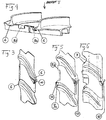
- FIG. 4, 5 show in Fig. 2 . 3 corresponding representation, a further embodiment of the present invention.
- Corresponding elements are designated by identical reference numerals, so that reference is made to the rest of the description and will be discussed below only the differences from other embodiments.
- Fig. 4 5 is the second undercut 9a formed integrally with the second stop 14 by a tab is turned over and at the same time engages under the axial shoulder 6 and rotatably sets the balancing body against the rotational direction of this. Distance therefrom in the direction of rotation sets the second radial flange 8.2 the balancing body in the axial direction. In this way, the individual areas of the balancing body can be better optimized for their respective functionality.
- the undercut 9a can already be formed prior to the attachment of the balancing body 1 on the outer shroud 4, 5, the balancing body are hooked accordingly. Similarly, the undercut can be formed only after the radial attachment of the balancing body 1 on the outer shroud 4, 5 by plastic folding the tab or be.
- FIG. 6 shows in Fig. 5 corresponding representation, a further embodiment of the present invention.
- Corresponding elements are again denoted by identical reference numerals, so that reference is made to the rest of the description and will be discussed below only the differences from other embodiments.
- Fig. 6 do not extend the axial paragraphs as in the embodiments of Fig. 1-5 axially away from the airfoil assembly 2, 3 of the blade assembly, but axially toward the airfoil assembly or ring. They are correspondingly formed by material recesses 7 against an edge of the outer cover tape. Also in the execution of Fig. 6 is the first undercut 10 with the web-like first stop 11 (see Fig. 1 ), the first - as in Fig. 6 indicated by dashed lines - plastically away from the blades 2, 3 (to the right in Fig. 6 ) is bent to the bending line B (see. Fig. 1 ) plastically towards the blades 2, 3 (left in Fig. 6 ) bent.
- the web-like first stop 11 is brought into alignment with the axial shoulder 7 and thereby clamped.
- the contacting of the end face of the material recess 7 by the stop 11 bent inward towards the ring is also referred to as alignment in the sense of the present invention, since this arrangement prevents movement of the balancing body in the direction of rotation.
- the balancing body 1 is fixed both in the radial and in the circumferential direction of the outer shroud.
Landscapes
- Engineering & Computer Science (AREA)
- General Engineering & Computer Science (AREA)
- Mechanical Engineering (AREA)
- Physics & Mathematics (AREA)
- Acoustics & Sound (AREA)
- Aviation & Aerospace Engineering (AREA)
- Structures Of Non-Positive Displacement Pumps (AREA)
Priority Applications (4)
| Application Number | Priority Date | Filing Date | Title |
|---|---|---|---|
| ES13169289.9T ES2640366T3 (es) | 2013-05-27 | 2013-05-27 | Cuerpo de equilibrado para una disposición de álabes |
| PL13169289T PL2808486T3 (pl) | 2013-05-27 | 2013-05-27 | Element wyważający do układu łopatek wirujących |
| EP13169289.9A EP2808486B1 (de) | 2013-05-27 | 2013-05-27 | Wuchtkörper für eine Laufschaufelanordnung |
| US14/219,726 US9816379B2 (en) | 2013-05-27 | 2014-03-19 | Balancing body for a continuous blade arrangement |
Applications Claiming Priority (1)
| Application Number | Priority Date | Filing Date | Title |
|---|---|---|---|
| EP13169289.9A EP2808486B1 (de) | 2013-05-27 | 2013-05-27 | Wuchtkörper für eine Laufschaufelanordnung |
Publications (2)
| Publication Number | Publication Date |
|---|---|
| EP2808486A1 EP2808486A1 (de) | 2014-12-03 |
| EP2808486B1 true EP2808486B1 (de) | 2017-08-30 |
Family
ID=48534197
Family Applications (1)
| Application Number | Title | Priority Date | Filing Date |
|---|---|---|---|
| EP13169289.9A Not-in-force EP2808486B1 (de) | 2013-05-27 | 2013-05-27 | Wuchtkörper für eine Laufschaufelanordnung |
Country Status (4)
| Country | Link |
|---|---|
| US (1) | US9816379B2 (pl) |
| EP (1) | EP2808486B1 (pl) |
| ES (1) | ES2640366T3 (pl) |
| PL (1) | PL2808486T3 (pl) |
Families Citing this family (4)
| Publication number | Priority date | Publication date | Assignee | Title |
|---|---|---|---|---|
| DE102016210454A1 (de) * | 2016-06-14 | 2017-12-14 | MTU Aero Engines AG | Wuchtgewicht für eine Laufschaufel einer Turbinenstufe |
| US10570765B2 (en) * | 2016-11-17 | 2020-02-25 | United Technologies Corporation | Endwall arc segments with cover across joint |
| FR3066780B1 (fr) * | 2017-05-24 | 2019-07-19 | Safran Aircraft Engines | Piece amovible anti-usure pour talon d'aube |
| FR3096105B1 (fr) * | 2019-05-16 | 2021-11-05 | Safran Aircraft Engines | rotor de turbomachine à gaz à masselotte |
Family Cites Families (10)
| Publication number | Priority date | Publication date | Assignee | Title |
|---|---|---|---|---|
| US3588269A (en) * | 1969-06-25 | 1971-06-28 | Gen Motors Corp | Variable vane cascades |
| US5011374A (en) | 1987-11-17 | 1991-04-30 | General Electric Company | Method and apparatus for balancing turbine rotors |
| GB2251897B (en) * | 1991-01-15 | 1994-11-30 | Rolls Royce Plc | A rotor |
| DE4300773C1 (de) * | 1993-01-14 | 1993-11-18 | Mtu Muenchen Gmbh | Einrichtung zur axialen Laufschaufelsicherung und zur Beseitigung von Rotorunwuchten für axial durchströmte Verdichter oder Turbinen |
| US7108480B2 (en) | 2004-05-28 | 2006-09-19 | General Electric Company | Method and apparatus for balancing turbine rotors |
| DE102004026365B4 (de) * | 2004-05-29 | 2006-08-31 | Mtu Aero Engines Gmbh | Einrichtung zur Unwuchtkompensation |
| US8186954B2 (en) * | 2008-09-30 | 2012-05-29 | General Electric Company | Gas turbine engine rotor and balance weight therefor |
| US8382436B2 (en) * | 2009-01-06 | 2013-02-26 | General Electric Company | Non-integral turbine blade platforms and systems |
| ES2542160T3 (es) | 2009-03-09 | 2015-07-31 | Ge Avio S.R.L. | Rotor para turbomáquinas con álabes con corona |
| US8936440B2 (en) * | 2011-05-26 | 2015-01-20 | United Technologies Corporation | Hybrid rotor disk assembly with ceramic matrix composites platform for a gas turbine engine |
-
2013
- 2013-05-27 EP EP13169289.9A patent/EP2808486B1/de not_active Not-in-force
- 2013-05-27 PL PL13169289T patent/PL2808486T3/pl unknown
- 2013-05-27 ES ES13169289.9T patent/ES2640366T3/es active Active
-
2014
- 2014-03-19 US US14/219,726 patent/US9816379B2/en not_active Expired - Fee Related
Non-Patent Citations (1)
| Title |
|---|
| None * |
Also Published As
| Publication number | Publication date |
|---|---|
| US20140348655A1 (en) | 2014-11-27 |
| EP2808486A1 (de) | 2014-12-03 |
| PL2808486T3 (pl) | 2017-11-30 |
| US9816379B2 (en) | 2017-11-14 |
| ES2640366T3 (es) | 2017-11-02 |
Similar Documents
| Publication | Publication Date | Title |
|---|---|---|
| EP2789802B1 (de) | Schaufelgitter für eine Turbomaschine und zugehöriges Herstellungsverfahren | |
| EP2478186B1 (de) | Rotor einer Turbomaschine | |
| CH697806A2 (de) | Turbinenschaufel-Deckbandkantenprofil. | |
| EP2873807A1 (de) | Abdeckplatte, Laufschaufel, Radscheibe, Bolzen und Gasturbine | |
| EP2617949B1 (de) | Strömungsmaschinen-Dichtungsanordnung | |
| EP2927503A1 (de) | Gasturbinenverdichter, Flugtriebwerk und Auslegungsverfahren | |
| EP3273001B1 (de) | Verfahren zum herstellen eines tandem-leitschaufelsegments | |
| EP2808486B1 (de) | Wuchtkörper für eine Laufschaufelanordnung | |
| EP3287611A1 (de) | Gasturbine und verfahren zum aufhängen eines turbinen-leitschaufelsegments einer gasturbine | |
| EP3536974A1 (de) | Gasturbinenverdichter | |
| EP2918776B1 (de) | Verfahren zur herstellung eines doppelreihigen schaufelrads für eine strömungsmaschine und doppelreihiges schaufelrad | |
| EP2607625A1 (de) | Turbomaschine und Turbomaschinenstufe | |
| EP2410131B1 (de) | Rotor einer Turbomaschine | |
| EP2787178B1 (de) | Leitschaufelanordnung | |
| EP3390784B1 (de) | Strömungsmaschine mit mehreren leitschaufelstufen und verfahren zur teilweisen demontage einer solchen strömungsmaschine | |
| EP2730745B1 (de) | Schaufelanordnung für eine Turbomaschine | |
| EP2696078B1 (de) | Beschaufelter Rotor für eine Turbomaschine und zugehöriges Montageverfahren | |
| DE60034440T2 (de) | Axial gezinktes segment zum befestigen turbinenschaufeln an einem turbinenrad und einbaumethoden dafür | |
| EP3358135B1 (de) | Konturierung einer schaufelgitterplattform | |
| EP3327258A1 (de) | Eintrittsleitrad für eine turbomaschine | |
| EP3312388A1 (de) | Pultdach dichtfin | |
| EP3401503A1 (de) | Rotorvorrichtung einer strömungsmaschine | |
| DE102011052037A1 (de) | Strömungsteileranordnung für Dampfturboantrieb und Verfahren | |
| EP3375977A1 (de) | Konturierung einer schaufelgitterplattform | |
| EP3404211A1 (de) | Schaufelgittersegment für eine turbine mit konturierter plattformoberfläche, zugehörige schaufelgitter, schaufelkanal, plattform, turbine und flugzeugtriebwerk |
Legal Events
| Date | Code | Title | Description |
|---|---|---|---|
| PUAI | Public reference made under article 153(3) epc to a published international application that has entered the european phase |
Free format text: ORIGINAL CODE: 0009012 |
|
| 17P | Request for examination filed |
Effective date: 20130527 |
|
| AK | Designated contracting states |
Kind code of ref document: A1 Designated state(s): AL AT BE BG CH CY CZ DE DK EE ES FI FR GB GR HR HU IE IS IT LI LT LU LV MC MK MT NL NO PL PT RO RS SE SI SK SM TR |
|
| AX | Request for extension of the european patent |
Extension state: BA ME |
|
| R17P | Request for examination filed (corrected) |
Effective date: 20150529 |
|
| RBV | Designated contracting states (corrected) |
Designated state(s): AL AT BE BG CH CY CZ DE DK EE ES FI FR GB GR HR HU IE IS IT LI LT LU LV MC MK MT NL NO PL PT RO RS SE SI SK SM TR |
|
| 17Q | First examination report despatched |
Effective date: 20161014 |
|
| GRAP | Despatch of communication of intention to grant a patent |
Free format text: ORIGINAL CODE: EPIDOSNIGR1 |
|
| INTG | Intention to grant announced |
Effective date: 20170531 |
|
| GRAS | Grant fee paid |
Free format text: ORIGINAL CODE: EPIDOSNIGR3 |
|
| GRAA | (expected) grant |
Free format text: ORIGINAL CODE: 0009210 |
|
| AK | Designated contracting states |
Kind code of ref document: B1 Designated state(s): AL AT BE BG CH CY CZ DE DK EE ES FI FR GB GR HR HU IE IS IT LI LT LU LV MC MK MT NL NO PL PT RO RS SE SI SK SM TR |
|
| REG | Reference to a national code |
Ref country code: GB Ref legal event code: FG4D Free format text: NOT ENGLISH |
|
| REG | Reference to a national code |
Ref country code: CH Ref legal event code: EP |
|
| REG | Reference to a national code |
Ref country code: AT Ref legal event code: REF Ref document number: 923756 Country of ref document: AT Kind code of ref document: T Effective date: 20170915 |
|
| REG | Reference to a national code |
Ref country code: IE Ref legal event code: FG4D Free format text: LANGUAGE OF EP DOCUMENT: GERMAN |
|
| REG | Reference to a national code |
Ref country code: DE Ref legal event code: R096 Ref document number: 502013008179 Country of ref document: DE |
|
| REG | Reference to a national code |
Ref country code: ES Ref legal event code: FG2A Ref document number: 2640366 Country of ref document: ES Kind code of ref document: T3 Effective date: 20171102 |
|
| REG | Reference to a national code |
Ref country code: NL Ref legal event code: MP Effective date: 20170830 |
|
| REG | Reference to a national code |
Ref country code: LT Ref legal event code: MG4D |
|
| PG25 | Lapsed in a contracting state [announced via postgrant information from national office to epo] |
Ref country code: FI Free format text: LAPSE BECAUSE OF FAILURE TO SUBMIT A TRANSLATION OF THE DESCRIPTION OR TO PAY THE FEE WITHIN THE PRESCRIBED TIME-LIMIT Effective date: 20170830 Ref country code: NO Free format text: LAPSE BECAUSE OF FAILURE TO SUBMIT A TRANSLATION OF THE DESCRIPTION OR TO PAY THE FEE WITHIN THE PRESCRIBED TIME-LIMIT Effective date: 20171130 Ref country code: HR Free format text: LAPSE BECAUSE OF FAILURE TO SUBMIT A TRANSLATION OF THE DESCRIPTION OR TO PAY THE FEE WITHIN THE PRESCRIBED TIME-LIMIT Effective date: 20170830 Ref country code: LT Free format text: LAPSE BECAUSE OF FAILURE TO SUBMIT A TRANSLATION OF THE DESCRIPTION OR TO PAY THE FEE WITHIN THE PRESCRIBED TIME-LIMIT Effective date: 20170830 Ref country code: SE Free format text: LAPSE BECAUSE OF FAILURE TO SUBMIT A TRANSLATION OF THE DESCRIPTION OR TO PAY THE FEE WITHIN THE PRESCRIBED TIME-LIMIT Effective date: 20170830 |
|
| PG25 | Lapsed in a contracting state [announced via postgrant information from national office to epo] |
Ref country code: LV Free format text: LAPSE BECAUSE OF FAILURE TO SUBMIT A TRANSLATION OF THE DESCRIPTION OR TO PAY THE FEE WITHIN THE PRESCRIBED TIME-LIMIT Effective date: 20170830 Ref country code: RS Free format text: LAPSE BECAUSE OF FAILURE TO SUBMIT A TRANSLATION OF THE DESCRIPTION OR TO PAY THE FEE WITHIN THE PRESCRIBED TIME-LIMIT Effective date: 20170830 Ref country code: BG Free format text: LAPSE BECAUSE OF FAILURE TO SUBMIT A TRANSLATION OF THE DESCRIPTION OR TO PAY THE FEE WITHIN THE PRESCRIBED TIME-LIMIT Effective date: 20171130 Ref country code: GR Free format text: LAPSE BECAUSE OF FAILURE TO SUBMIT A TRANSLATION OF THE DESCRIPTION OR TO PAY THE FEE WITHIN THE PRESCRIBED TIME-LIMIT Effective date: 20171201 Ref country code: IS Free format text: LAPSE BECAUSE OF FAILURE TO SUBMIT A TRANSLATION OF THE DESCRIPTION OR TO PAY THE FEE WITHIN THE PRESCRIBED TIME-LIMIT Effective date: 20171230 |
|
| PG25 | Lapsed in a contracting state [announced via postgrant information from national office to epo] |
Ref country code: NL Free format text: LAPSE BECAUSE OF FAILURE TO SUBMIT A TRANSLATION OF THE DESCRIPTION OR TO PAY THE FEE WITHIN THE PRESCRIBED TIME-LIMIT Effective date: 20170830 |
|
| PG25 | Lapsed in a contracting state [announced via postgrant information from national office to epo] |
Ref country code: CZ Free format text: LAPSE BECAUSE OF FAILURE TO SUBMIT A TRANSLATION OF THE DESCRIPTION OR TO PAY THE FEE WITHIN THE PRESCRIBED TIME-LIMIT Effective date: 20170830 Ref country code: RO Free format text: LAPSE BECAUSE OF FAILURE TO SUBMIT A TRANSLATION OF THE DESCRIPTION OR TO PAY THE FEE WITHIN THE PRESCRIBED TIME-LIMIT Effective date: 20170830 Ref country code: DK Free format text: LAPSE BECAUSE OF FAILURE TO SUBMIT A TRANSLATION OF THE DESCRIPTION OR TO PAY THE FEE WITHIN THE PRESCRIBED TIME-LIMIT Effective date: 20170830 |
|
| REG | Reference to a national code |
Ref country code: FR Ref legal event code: PLFP Year of fee payment: 6 |
|
| PG25 | Lapsed in a contracting state [announced via postgrant information from national office to epo] |
Ref country code: SM Free format text: LAPSE BECAUSE OF FAILURE TO SUBMIT A TRANSLATION OF THE DESCRIPTION OR TO PAY THE FEE WITHIN THE PRESCRIBED TIME-LIMIT Effective date: 20170830 Ref country code: SK Free format text: LAPSE BECAUSE OF FAILURE TO SUBMIT A TRANSLATION OF THE DESCRIPTION OR TO PAY THE FEE WITHIN THE PRESCRIBED TIME-LIMIT Effective date: 20170830 Ref country code: EE Free format text: LAPSE BECAUSE OF FAILURE TO SUBMIT A TRANSLATION OF THE DESCRIPTION OR TO PAY THE FEE WITHIN THE PRESCRIBED TIME-LIMIT Effective date: 20170830 Ref country code: IT Free format text: LAPSE BECAUSE OF FAILURE TO SUBMIT A TRANSLATION OF THE DESCRIPTION OR TO PAY THE FEE WITHIN THE PRESCRIBED TIME-LIMIT Effective date: 20170830 |
|
| REG | Reference to a national code |
Ref country code: DE Ref legal event code: R097 Ref document number: 502013008179 Country of ref document: DE |
|
| PLBE | No opposition filed within time limit |
Free format text: ORIGINAL CODE: 0009261 |
|
| STAA | Information on the status of an ep patent application or granted ep patent |
Free format text: STATUS: NO OPPOSITION FILED WITHIN TIME LIMIT |
|
| 26N | No opposition filed |
Effective date: 20180531 |
|
| PG25 | Lapsed in a contracting state [announced via postgrant information from national office to epo] |
Ref country code: SI Free format text: LAPSE BECAUSE OF FAILURE TO SUBMIT A TRANSLATION OF THE DESCRIPTION OR TO PAY THE FEE WITHIN THE PRESCRIBED TIME-LIMIT Effective date: 20170830 |
|
| PG25 | Lapsed in a contracting state [announced via postgrant information from national office to epo] |
Ref country code: MT Free format text: LAPSE BECAUSE OF FAILURE TO SUBMIT A TRANSLATION OF THE DESCRIPTION OR TO PAY THE FEE WITHIN THE PRESCRIBED TIME-LIMIT Effective date: 20170830 |
|
| REG | Reference to a national code |
Ref country code: CH Ref legal event code: PL |
|
| REG | Reference to a national code |
Ref country code: BE Ref legal event code: MM Effective date: 20180531 |
|
| PG25 | Lapsed in a contracting state [announced via postgrant information from national office to epo] |
Ref country code: MC Free format text: LAPSE BECAUSE OF FAILURE TO SUBMIT A TRANSLATION OF THE DESCRIPTION OR TO PAY THE FEE WITHIN THE PRESCRIBED TIME-LIMIT Effective date: 20170830 |
|
| REG | Reference to a national code |
Ref country code: IE Ref legal event code: MM4A |
|
| PG25 | Lapsed in a contracting state [announced via postgrant information from national office to epo] |
Ref country code: CH Free format text: LAPSE BECAUSE OF NON-PAYMENT OF DUE FEES Effective date: 20180531 Ref country code: LI Free format text: LAPSE BECAUSE OF NON-PAYMENT OF DUE FEES Effective date: 20180531 |
|
| PG25 | Lapsed in a contracting state [announced via postgrant information from national office to epo] |
Ref country code: LU Free format text: LAPSE BECAUSE OF NON-PAYMENT OF DUE FEES Effective date: 20180527 |
|
| PG25 | Lapsed in a contracting state [announced via postgrant information from national office to epo] |
Ref country code: IE Free format text: LAPSE BECAUSE OF NON-PAYMENT OF DUE FEES Effective date: 20180527 |
|
| PG25 | Lapsed in a contracting state [announced via postgrant information from national office to epo] |
Ref country code: BE Free format text: LAPSE BECAUSE OF NON-PAYMENT OF DUE FEES Effective date: 20180531 |
|
| REG | Reference to a national code |
Ref country code: AT Ref legal event code: MM01 Ref document number: 923756 Country of ref document: AT Kind code of ref document: T Effective date: 20180527 |
|
| PG25 | Lapsed in a contracting state [announced via postgrant information from national office to epo] |
Ref country code: AT Free format text: LAPSE BECAUSE OF NON-PAYMENT OF DUE FEES Effective date: 20180527 |
|
| PG25 | Lapsed in a contracting state [announced via postgrant information from national office to epo] |
Ref country code: TR Free format text: LAPSE BECAUSE OF FAILURE TO SUBMIT A TRANSLATION OF THE DESCRIPTION OR TO PAY THE FEE WITHIN THE PRESCRIBED TIME-LIMIT Effective date: 20170830 |
|
| PG25 | Lapsed in a contracting state [announced via postgrant information from national office to epo] |
Ref country code: PT Free format text: LAPSE BECAUSE OF FAILURE TO SUBMIT A TRANSLATION OF THE DESCRIPTION OR TO PAY THE FEE WITHIN THE PRESCRIBED TIME-LIMIT Effective date: 20170830 Ref country code: HU Free format text: LAPSE BECAUSE OF FAILURE TO SUBMIT A TRANSLATION OF THE DESCRIPTION OR TO PAY THE FEE WITHIN THE PRESCRIBED TIME-LIMIT; INVALID AB INITIO Effective date: 20130527 |
|
| PG25 | Lapsed in a contracting state [announced via postgrant information from national office to epo] |
Ref country code: CY Free format text: LAPSE BECAUSE OF FAILURE TO SUBMIT A TRANSLATION OF THE DESCRIPTION OR TO PAY THE FEE WITHIN THE PRESCRIBED TIME-LIMIT Effective date: 20170830 Ref country code: MK Free format text: LAPSE BECAUSE OF NON-PAYMENT OF DUE FEES Effective date: 20170830 |
|
| PG25 | Lapsed in a contracting state [announced via postgrant information from national office to epo] |
Ref country code: AL Free format text: LAPSE BECAUSE OF FAILURE TO SUBMIT A TRANSLATION OF THE DESCRIPTION OR TO PAY THE FEE WITHIN THE PRESCRIBED TIME-LIMIT Effective date: 20170830 |
|
| PGFP | Annual fee paid to national office [announced via postgrant information from national office to epo] |
Ref country code: FR Payment date: 20230517 Year of fee payment: 11 Ref country code: ES Payment date: 20230621 Year of fee payment: 11 Ref country code: DE Payment date: 20230519 Year of fee payment: 11 |
|
| PGFP | Annual fee paid to national office [announced via postgrant information from national office to epo] |
Ref country code: PL Payment date: 20230524 Year of fee payment: 11 |
|
| PGFP | Annual fee paid to national office [announced via postgrant information from national office to epo] |
Ref country code: GB Payment date: 20230522 Year of fee payment: 11 |
|
| REG | Reference to a national code |
Ref country code: DE Ref legal event code: R119 Ref document number: 502013008179 Country of ref document: DE |
|
| GBPC | Gb: european patent ceased through non-payment of renewal fee |
Effective date: 20240527 |
|
| PG25 | Lapsed in a contracting state [announced via postgrant information from national office to epo] |
Ref country code: DE Free format text: LAPSE BECAUSE OF NON-PAYMENT OF DUE FEES Effective date: 20241203 |
|
| PG25 | Lapsed in a contracting state [announced via postgrant information from national office to epo] |
Ref country code: FR Free format text: LAPSE BECAUSE OF NON-PAYMENT OF DUE FEES Effective date: 20240531 |
|
| PG25 | Lapsed in a contracting state [announced via postgrant information from national office to epo] |
Ref country code: GB Free format text: LAPSE BECAUSE OF NON-PAYMENT OF DUE FEES Effective date: 20240527 |
|
| REG | Reference to a national code |
Ref country code: ES Ref legal event code: FD2A Effective date: 20250702 |
|
| PG25 | Lapsed in a contracting state [announced via postgrant information from national office to epo] |
Ref country code: ES Free format text: LAPSE BECAUSE OF NON-PAYMENT OF DUE FEES Effective date: 20240528 |
|
| PG25 | Lapsed in a contracting state [announced via postgrant information from national office to epo] |
Ref country code: PL Free format text: LAPSE BECAUSE OF NON-PAYMENT OF DUE FEES Effective date: 20240527 |