EP2808486B1 - Balancing component for a rotor blade arrangement - Google Patents
Balancing component for a rotor blade arrangement Download PDFInfo
- Publication number
- EP2808486B1 EP2808486B1 EP13169289.9A EP13169289A EP2808486B1 EP 2808486 B1 EP2808486 B1 EP 2808486B1 EP 13169289 A EP13169289 A EP 13169289A EP 2808486 B1 EP2808486 B1 EP 2808486B1
- Authority
- EP
- European Patent Office
- Prior art keywords
- balancing body
- rotor blade
- ring
- blade arrangement
- stop
- Prior art date
- Legal status (The legal status is an assumption and is not a legal conclusion. Google has not performed a legal analysis and makes no representation as to the accuracy of the status listed.)
- Active
Links
Images
Classifications
-
- F—MECHANICAL ENGINEERING; LIGHTING; HEATING; WEAPONS; BLASTING
- F01—MACHINES OR ENGINES IN GENERAL; ENGINE PLANTS IN GENERAL; STEAM ENGINES
- F01D—NON-POSITIVE DISPLACEMENT MACHINES OR ENGINES, e.g. STEAM TURBINES
- F01D5/00—Blades; Blade-carrying members; Heating, heat-insulating, cooling or antivibration means on the blades or the members
- F01D5/02—Blade-carrying members, e.g. rotors
- F01D5/027—Arrangements for balancing
-
- F—MECHANICAL ENGINEERING; LIGHTING; HEATING; WEAPONS; BLASTING
- F01—MACHINES OR ENGINES IN GENERAL; ENGINE PLANTS IN GENERAL; STEAM ENGINES
- F01D—NON-POSITIVE DISPLACEMENT MACHINES OR ENGINES, e.g. STEAM TURBINES
- F01D25/00—Component parts, details, or accessories, not provided for in, or of interest apart from, other groups
- F01D25/28—Supporting or mounting arrangements, e.g. for turbine casing
-
- F—MECHANICAL ENGINEERING; LIGHTING; HEATING; WEAPONS; BLASTING
- F01—MACHINES OR ENGINES IN GENERAL; ENGINE PLANTS IN GENERAL; STEAM ENGINES
- F01D—NON-POSITIVE DISPLACEMENT MACHINES OR ENGINES, e.g. STEAM TURBINES
- F01D5/00—Blades; Blade-carrying members; Heating, heat-insulating, cooling or antivibration means on the blades or the members
- F01D5/12—Blades
- F01D5/22—Blade-to-blade connections, e.g. for damping vibrations
- F01D5/225—Blade-to-blade connections, e.g. for damping vibrations by shrouding
-
- F—MECHANICAL ENGINEERING; LIGHTING; HEATING; WEAPONS; BLASTING
- F16—ENGINEERING ELEMENTS AND UNITS; GENERAL MEASURES FOR PRODUCING AND MAINTAINING EFFECTIVE FUNCTIONING OF MACHINES OR INSTALLATIONS; THERMAL INSULATION IN GENERAL
- F16F—SPRINGS; SHOCK-ABSORBERS; MEANS FOR DAMPING VIBRATION
- F16F15/00—Suppression of vibrations in systems; Means or arrangements for avoiding or reducing out-of-balance forces, e.g. due to motion
- F16F15/32—Correcting- or balancing-weights or equivalent means for balancing rotating bodies, e.g. vehicle wheels
-
- F—MECHANICAL ENGINEERING; LIGHTING; HEATING; WEAPONS; BLASTING
- F05—INDEXING SCHEMES RELATING TO ENGINES OR PUMPS IN VARIOUS SUBCLASSES OF CLASSES F01-F04
- F05D—INDEXING SCHEME FOR ASPECTS RELATING TO NON-POSITIVE-DISPLACEMENT MACHINES OR ENGINES, GAS-TURBINES OR JET-PROPULSION PLANTS
- F05D2230/00—Manufacture
- F05D2230/60—Assembly methods
-
- F—MECHANICAL ENGINEERING; LIGHTING; HEATING; WEAPONS; BLASTING
- F05—INDEXING SCHEMES RELATING TO ENGINES OR PUMPS IN VARIOUS SUBCLASSES OF CLASSES F01-F04
- F05D—INDEXING SCHEME FOR ASPECTS RELATING TO NON-POSITIVE-DISPLACEMENT MACHINES OR ENGINES, GAS-TURBINES OR JET-PROPULSION PLANTS
- F05D2260/00—Function
- F05D2260/15—Load balancing
-
- Y—GENERAL TAGGING OF NEW TECHNOLOGICAL DEVELOPMENTS; GENERAL TAGGING OF CROSS-SECTIONAL TECHNOLOGIES SPANNING OVER SEVERAL SECTIONS OF THE IPC; TECHNICAL SUBJECTS COVERED BY FORMER USPC CROSS-REFERENCE ART COLLECTIONS [XRACs] AND DIGESTS
- Y10—TECHNICAL SUBJECTS COVERED BY FORMER USPC
- Y10T—TECHNICAL SUBJECTS COVERED BY FORMER US CLASSIFICATION
- Y10T29/00—Metal working
- Y10T29/49—Method of mechanical manufacture
- Y10T29/49229—Prime mover or fluid pump making
- Y10T29/49236—Fluid pump or compressor making
- Y10T29/49245—Vane type or other rotary, e.g., fan
-
- Y—GENERAL TAGGING OF NEW TECHNOLOGICAL DEVELOPMENTS; GENERAL TAGGING OF CROSS-SECTIONAL TECHNOLOGIES SPANNING OVER SEVERAL SECTIONS OF THE IPC; TECHNICAL SUBJECTS COVERED BY FORMER USPC CROSS-REFERENCE ART COLLECTIONS [XRACs] AND DIGESTS
- Y10—TECHNICAL SUBJECTS COVERED BY FORMER USPC
- Y10T—TECHNICAL SUBJECTS COVERED BY FORMER US CLASSIFICATION
- Y10T29/00—Metal working
- Y10T29/49—Method of mechanical manufacture
- Y10T29/49316—Impeller making
- Y10T29/4932—Turbomachine making
Definitions
- the present invention relates to a balancing body for attachment to a ring of a blade assembly, a blade assembly of a compressor or turbine stage of a gas turbine having such a balancing body and a method for setting or releasing such balancing body of the blade assembly.
- An object of an embodiment of the present invention is to improve a gas turbine.
- One aspect of the present invention relates to a blade assembly of a compressor or turbine stage or for a compressor or turbine stage of a gas turbine and a gas turbine with such a compressor or turbine stage or blade assembly.
- the blade assembly includes a plurality of blade blades adjacent or distributed in a circumferential direction. These may be releasably or permanently attached to a rotor of the turbine (ntyp), in particular be formed integrally therewith.
- the blade assembly includes a ring defining a flow channel for a working fluid of the gas turbine.
- the ring is a one-piece or multi-part radially outer or outer ring or a so-called outer shroud, which may be connected to one or more blades.
- the ring may be a one-piece or multi-piece radially inner or inner ring or a so-called blade platform, which may be connected to one or more blade blades.
- One or more balancing bodies are or are arranged, preferably at one or more predetermined circumferential positions, on the ring in each case between two blade leaves of the rotor blade arrangement which are adjacent in a circumferential direction.
- a balancing body engages in a circumferential direction a parting line between two adjacent ring parts.
- the mass or mass distribution of a balancing body can be represented in one embodiment by varying one or more recesses and / or by varying a wall thickness of the balancing body.
- a balancing body from the adjacent blades, between which it is disposed spaced apart in a circumferential direction and positively defines by one or in opposite directions by two axial paragraphs of the ring. This can be reduced by balancing body in one embodiment, the risk of deterioration of airfoils. Additionally or alternatively, the assembly and / or disassembly of balancing bodies, in particular in situ on the arranged in the gas turbine rotor blade assembly, preferably through a thrust nozzle of the gas turbine through, can be improved.
- a balancer for attachment to a ring of a blade assembly of a compressor or turbine stage of a gas turbine has a first stop for positively locking the balancer in a circumferential direction on a first axial shoulder of the ring.
- at least one limitation of a clearance in the circumferential direction in a further development, is a rotationally fixed one or - understood at least substantially - backlash-free attachment.
- opposite circumferential direction or in the opposite direction to the first stop-paragraph pair of the balancing body can be fixed in a form-fitting manner by a second stop of the balancing body to a second axial shoulder of the ring or be.
- the balancing body can also be fixed in the further circumferential direction by an airfoil of the rotor blade arrangement.
- the one circumferential direction may be opposite one direction of rotation of the gas turbine or this, the other, opposite circumferential direction may accordingly be opposite to the direction of rotation of the gas turbine or the direction of rotation.
- the first stop-paragraph pair may determine the balancing body in or against the direction of rotation, an opposing second stop-paragraph pair corresponding to opposite or in the direction of rotation.
- a stop and an axial shoulder are understood to mean, in particular, a surface, in particular an end surface, which extends, at least substantially, in the axial direction and in the radial direction, wherein the surface forms a right angle with the circumferential direction, at least substantially or may be chamfered against them in or against the direction of rotation.
- the end face may in one embodiment, at least substantially, have the wall thickness of the remaining ring or be formed as a material projection or - Wegten of the ring in the axial direction.
- the shoulder may extend axially away from an airfoil assembly of the blade assembly or may be formed as an axial material projection.
- a lever arm for limiting, in particular preventing, a rotation of the balancing body about a radial axis can advantageously be increased.
- the shoulder may extend axially toward the airfoil assembly of the blade assembly, or may be formed as an axial material recess opposite an axial outer edge of the ring.
- an axial projection of the ring can be reduced or avoided.
- the stop / heel pairs can set the balancer on or gegensinning in one or two opposite circumferential directions with play or limit its movement in the or the circumferential directions.
- the balancing body as stated above, also be - at least substantially free of play - be rotationally fixed or.
- the balancing body is clamped in the circumferential direction.
- at least one stop for the positive fixing of the balancing body in a circumferential direction can extend in the manner of a web or nose in the radial direction or can be made yielding in this circumferential direction.
- the balancing body in one embodiment has a first and an axially spaced second radial flange, which is connected by an axial web to the first radial flange.
- the two radial flanges overlap two axial end faces of the ring and fix it axially with or without play.
- the ring is or is axially clamped between the first and second radial flange.
- the first and / or second radial flange may be formed yielding.
- a radial flange can, seen in an embodiment in the direction of rotation, converge towards the ring, in particular beveled in the direction of rotation. In this way, in one embodiment, a snagging of the radial flange can be prevented.
- a stop for the positive fixing of the balancing body can be arranged in a circumferential direction on a radial flange, in particular be formed integrally therewith.
- the first and second stops can be arranged on circumferentially opposite sides of the same radial flange.
- the first stop is disposed on the first radial flange, the second stop on the circumferentially opposite side of the axially spaced second radial flange.
- the stop may, as stated above, web-like or nose-like extend in the radial direction. Accordingly, a web-like or nose-like stop can be formed by a radial cut in a radial flange. In this way, the web-like stopper can yield elastically or plastically in a circumferential direction into the recess.
- the balancing body in one embodiment has one or two, in particular axially spaced, undercuts which engage behind or under the ring.
- An undercut can be arranged in a development on a radial flange for positive fixing of the balancing body in the axial direction, in particular be formed integrally therewith.
- the undercut can be arranged on a stop for the positive fixing of the balancing body in a circumferential direction, in particular be formed integrally therewith. In this way, the definitions in the circumferential, radial and / or axial direction can be united.
- an undercut an axial shoulder of the ring behind or under which a stop of the balancing body determines this form-fitting in a circumferential direction.
- an undercut is formed by a folded flap, which also forms a stop for the positive fixing of the balancing body in the circumferential direction.
- At least one stop for the positive fixing of the balancing body in the circumferential direction in the axial direction to the blade blades of the blade assembly is elastically or plastically deformed and thus in or out of alignment, in particular in positive, preferably preloaded, contact, brought with the circumferentially opposite shoulder of the ring.
- an alignment or in-alignment is understood to mean, in particular, an arrangement such that the shoulder positively restricts a further movement of the stop in a circumferential direction, in particular that the shoulder contacts the stop and thus positively prevents a further movement of the stop in the circumferential direction.
- a stop of the balancing body in particular a part of a radial flange of the balancing body which is defined by an incision and defines the stop, can be elastically or plastically bent toward the ring or be aligned with an axial shoulder or To oppose this and set the balancing body so in the circumferential direction.
- a stop of the balancing body in particular one, preferably defined by an incision, part of a radial flange of the balancing body, which defines the stop, are elastically or plastically bent away from the ring or to be out of alignment with an axial shoulder his or this no longer be opposite, so that the balancing body is movable in the circumferential direction.
- the stop may have a predetermined bending line along which it can be elastically or plastically bent toward the ring or away from the ring.
- This bending line can be defined in particular by a thinning of the material and / or an incision which, in a development, can additionally form the abutment web or nose-like manner.
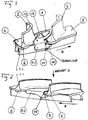
- Fig. 1, 2 show in perspective views ( Fig. 1 ) or in ( Fig. 2 ) a flow direction of a portion of an outer shroud of a blade assembly of a low-pressure turbine output stage of a gas turbine with a balancing body 1 according to an embodiment of the present invention.
- FIG. 1 In the views of Fig. 1, 2 are two blades 2, 3 of the blade assembly shown cut, which are each formed integrally with a shroud 4 and 5, which - together with other, not shown, shrouds form a ring in the form of a multi-part outer shroud.
- 3.1 (cf. Fig. 2 ) or 4.1 (cf. Fig. 1 ) is an input ( Fig. 2 ) or trailing edge ( Fig. 1 ) of an airfoil.
- Fig. 2 with III a plan view direction of the view of Fig. 3 indicated.
- Each shroud 4, 5 has on axially opposite end faces in each case an axial shoulder 6, which in the embodiment of Fig. 1-3 is formed by an axial material projection.
- the balancing body 1 is arranged between the two blade leaves 2, 3 of the blade arrangement, which are adjacent in a direction of rotation R, and are spaced therefrom in the direction of rotation R.
- first radial flange 8.1 see. Fig. 1
- second radially spaced therefrom second radial flange 8.2 see. Fig. 2
- a recess 12 is formed to adjust a predetermined mass or mass distribution of the balancing body.
- a first stop 11 of the balancing body is designed to fix the balancing body in the rotational direction R at the first axial shoulder of the outer shroud in a form-fitting manner.
- the first stop 11 extends web-like or nose-like in the radial direction and is defined for this purpose by a radial incision. In this way, the web-like stop 11 is designed to be yielding in the direction of rotation R.
- a second stop 14 of the balancing body is formed in order to fix the balancing body in opposite directions or counter to the direction of rotation R on the axially opposite second axial shoulder 6 of the outer shroud in a form-fitting manner.
- Both radial flanges 8.1, 8.2 converge in the direction of rotation R, seen at the end, towards the outer shroud (upward in FIG Fig. 1, 2 ) to avoid entanglement with an inlet lining (not shown).
- Integral with the first radial flange 8.1 (see. Fig. 1 ) is formed a first undercut 10, the first axial shoulder of the outer shroud in the radial direction (vertically in Fig. 1, 2 ) engages under to fix the balancing body on this axial shoulder in the radial direction positively.
- integral with the second radial flange 8.2 (see. Fig. 2 ) formed a second undercut 9, which engages under the second axial shoulder 6 of the outer shroud in the radial direction to fix the balancing body on this axial shoulder in the radial direction positively.
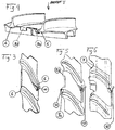
- FIG. 4, 5 show in Fig. 2 . 3 corresponding representation, a further embodiment of the present invention.
- Corresponding elements are designated by identical reference numerals, so that reference is made to the rest of the description and will be discussed below only the differences from other embodiments.
- Fig. 4 5 is the second undercut 9a formed integrally with the second stop 14 by a tab is turned over and at the same time engages under the axial shoulder 6 and rotatably sets the balancing body against the rotational direction of this. Distance therefrom in the direction of rotation sets the second radial flange 8.2 the balancing body in the axial direction. In this way, the individual areas of the balancing body can be better optimized for their respective functionality.
- the undercut 9a can already be formed prior to the attachment of the balancing body 1 on the outer shroud 4, 5, the balancing body are hooked accordingly. Similarly, the undercut can be formed only after the radial attachment of the balancing body 1 on the outer shroud 4, 5 by plastic folding the tab or be.
- FIG. 6 shows in Fig. 5 corresponding representation, a further embodiment of the present invention.
- Corresponding elements are again denoted by identical reference numerals, so that reference is made to the rest of the description and will be discussed below only the differences from other embodiments.
- Fig. 6 do not extend the axial paragraphs as in the embodiments of Fig. 1-5 axially away from the airfoil assembly 2, 3 of the blade assembly, but axially toward the airfoil assembly or ring. They are correspondingly formed by material recesses 7 against an edge of the outer cover tape. Also in the execution of Fig. 6 is the first undercut 10 with the web-like first stop 11 (see Fig. 1 ), the first - as in Fig. 6 indicated by dashed lines - plastically away from the blades 2, 3 (to the right in Fig. 6 ) is bent to the bending line B (see. Fig. 1 ) plastically towards the blades 2, 3 (left in Fig. 6 ) bent.
- the web-like first stop 11 is brought into alignment with the axial shoulder 7 and thereby clamped.
- the contacting of the end face of the material recess 7 by the stop 11 bent inward towards the ring is also referred to as alignment in the sense of the present invention, since this arrangement prevents movement of the balancing body in the direction of rotation.
- the balancing body 1 is fixed both in the radial and in the circumferential direction of the outer shroud.
Description
Die vorliegende Erfindung betrifft einen Wuchtkörper zur Befestigung an einem Ring einer Laufschaufelanordnung, eine Laufschaufelanordnung einer Verdichter- oder Turbinenstufe einer Gasturbine mit einem solchen Wuchtkörper sowie ein Verfahren zum Festlegen bzw. Lösen eines solchen Wuchtkörpers von der Laufschaufelanordnung.The present invention relates to a balancing body for attachment to a ring of a blade assembly, a blade assembly of a compressor or turbine stage of a gas turbine having such a balancing body and a method for setting or releasing such balancing body of the blade assembly.
Aus der
Eine Aufgabe einer Ausführung der vorliegenden Erfindung ist es, eine Gasturbine zu verbessern.An object of an embodiment of the present invention is to improve a gas turbine.
Diese Aufgabe wird durch einen Wuchtkörper mit den Merkmalen des Anspruchs 1 gelöst. Ansprüche 12, 13 stellen ein Verfahren zum Festlegen bzw. Lösen eines solchen Wuchtkörpers von der Laufschaufelanordnung unter Schutz. Vorteilhafte Ausführungsformen der Erfindung sind Gegenstand der Unteransprüche.This object is achieved by a balancing body with the features of
Ein Aspekt der vorliegenden Erfindung betrifft eine Laufschaufelanordnung einer Verdichter- oder Turbinenstufe bzw. für eine Verdichter- oder Turbinenstufe einer Gasturbine sowie eine Gasturbine mit einer solchen Verdichter- oder Turbinenstufe bzw. Laufschaufelanordnung. Die Laufschaufelanordnung weist mehrere in einer Umfangsrichtung benachbarte bzw. verteilte Laufschaufelblätter auf. Diese können lösbar oder dauerhaft an einem Rotor der Turbine(nstufe) befestigt, insbesondere integral mit diesem ausgebildet sein.One aspect of the present invention relates to a blade assembly of a compressor or turbine stage or for a compressor or turbine stage of a gas turbine and a gas turbine with such a compressor or turbine stage or blade assembly. The blade assembly includes a plurality of blade blades adjacent or distributed in a circumferential direction. These may be releasably or permanently attached to a rotor of the turbine (nstufe), in particular be formed integrally therewith.
Die Laufschaufelanordnung weist einen Ring auf, der einen Strömungskanal für ein Arbeitsmedium der Gasturbine begrenzt. In einer Ausführung ist der Ring ein ein- oder mehrteiliger radial äußerer bzw. Außenring bzw. ein sogenanntes Außendeckband, welches mit einem oder mehreren Laufschaufelblättern verbunden sein kann. Gleichermaßen kann der Ring ein ein- oder mehrteiliger radial innerer bzw. Innenring bzw. eine sogenannte Schaufelplattform sein, welche mit einem oder mehreren Laufschaufelblättern verbunden sein kann.The blade assembly includes a ring defining a flow channel for a working fluid of the gas turbine. In one embodiment, the ring is a one-piece or multi-part radially outer or outer ring or a so-called outer shroud, which may be connected to one or more blades. Similarly, the ring may be a one-piece or multi-piece radially inner or inner ring or a so-called blade platform, which may be connected to one or more blade blades.
Ein oder mehrere Wuchtkörper sind bzw. werden, vorzugsweise an einer bzw. mehreren vorgegebenen Umfangspositionen, an dem Ring jeweils zwischen zwei in einer Umfangsrichtung benachbarten Schaufelblättern der Laufschaufelanordnung angeordnet. In einer Ausführung übergreift ein Wuchtkörper in einer Umfangsrichtung eine Trennfuge zwischen zwei benachbarten Ringteilen. Die Masse bzw. Massenverteilung eines Wuchtkörpers kann in einer Ausführung durch Variation einer oder mehrerer Aussparungen und/oder durch Variation einer Wandstärke des Wuchtkörpers dargestellt werden.One or more balancing bodies are or are arranged, preferably at one or more predetermined circumferential positions, on the ring in each case between two blade leaves of the rotor blade arrangement which are adjacent in a circumferential direction. In one embodiment, a balancing body engages in a circumferential direction a parting line between two adjacent ring parts. The mass or mass distribution of a balancing body can be represented in one embodiment by varying one or more recesses and / or by varying a wall thickness of the balancing body.
Nach einem Aspekt der vorliegenden Erfindung ist ein Wuchtkörper von den benachbarten Schaufelblättern, zwischen denen er angeordnet ist, in einer Umfangsrichtung beabstandet und formschlüssig durch einen oder gegensinnig durch zwei axiale Absätze des Ringes festlegt. Hierdurch kann in einer Ausführung die Gefahr einer Beeinträchtigung von Schaufelblättern durch Wuchtkörper reduziert werden. Zusätzlich oder alternativ kann die Montage und/oder Demontage von Wuchtkörpern, insbesondere in situ an der in der Gasturbine angeordneten Laufschaufelanordnung, vorzugsweise durch eine Schubdüse der Gasturbine hindurch, verbessert werden.According to one aspect of the present invention is a balancing body from the adjacent blades, between which it is disposed spaced apart in a circumferential direction and positively defines by one or in opposite directions by two axial paragraphs of the ring. This can be reduced by balancing body in one embodiment, the risk of deterioration of airfoils. Additionally or alternatively, the assembly and / or disassembly of balancing bodies, in particular in situ on the arranged in the gas turbine rotor blade assembly, preferably through a thrust nozzle of the gas turbine through, can be improved.
Dementsprechend weist nach einem Aspekt der vorliegenden Erfindung ein Wuchtkörper zur Befestigung an einem Ring einer Laufschaufelanordnung einer Verdichter- oder Turbinenstufe einer Gasturbine einen ersten Anschlag zur formschlüssigen Festlegung des Wuchtkörpers in einer Umfangsrichtung an einem ersten axialen Absatz des Ringes auf. Unter einer Festlegung wird vorliegend wenigstens eine Begrenzung eines Spiels in der Umfangsrichtung, in einer Weiterbildung eine drehfeste bzw. - wenigstens im Wesentlichen - spielfreie Befestigung verstanden. In einer weiteren, entgegengesetzten Umfangsrichtung bzw. gegensinnig zum ersten Anschlag-Absatz-Paar kann der Wuchtkörper in einer Ausführung formschlüssig durch einen zweiten Anschlag des Wuchtkörpers an einem zweiten axialen Absatz des Ringes festgelegt werden bzw. sein. Gleichermaßen kann der Wuchtkörper in der weiteren Umfangsrichtung auch durch ein Schaufelblatt der Laufschaufelanordnung festgelegt sein. Die eine Umfangsrichtung kann eine Rotationsrichtung der Gasturbine oder dieser entgegengesetzt sein, die weitere, entgegengesetzte Umfangsrichtung kann dementsprechend der Rotationsrichtung der Gasturbine entgegengesetzt oder die Rotationsrichtung sein. Mit anderen Worten kann das erste Anschlag-Absatz-Paar den Wuchtkörper in oder entgegen der Rotationsrichtung festlegen, ein gegensinniges zweites Anschlag-Absatz-Paar entsprechend entgegen oder in der Rotationsrichtung.Accordingly, according to one aspect of the present invention, a balancer for attachment to a ring of a blade assembly of a compressor or turbine stage of a gas turbine has a first stop for positively locking the balancer in a circumferential direction on a first axial shoulder of the ring. In the present case, at least one limitation of a clearance in the circumferential direction, in a further development, is a rotationally fixed one or - understood at least substantially - backlash-free attachment. In another, opposite circumferential direction or in the opposite direction to the first stop-paragraph pair of the balancing body can be fixed in a form-fitting manner by a second stop of the balancing body to a second axial shoulder of the ring or be. Equally, the balancing body can also be fixed in the further circumferential direction by an airfoil of the rotor blade arrangement. The one circumferential direction may be opposite one direction of rotation of the gas turbine or this, the other, opposite circumferential direction may accordingly be opposite to the direction of rotation of the gas turbine or the direction of rotation. In other words, the first stop-paragraph pair may determine the balancing body in or against the direction of rotation, an opposing second stop-paragraph pair corresponding to opposite or in the direction of rotation.
Unter einem Anschlag und einem axialen Absatz wird vorliegend insbesondere eine Fläche, insbesondere eine Stirnfläche, verstanden, die sich, wenigstens im Wesentlichen, in axialer Richtung und in radialer Richtung erstreckt, wobei die Fläche mit der Umfangsrichtung, wenigstens im Wesentlichen, einen rechten Winkel bildet oder auch gegen diese in oder entgegen der Rotationsrichtung abgeschrägt sein kann. Die Stirnfläche kann in einer Ausführung, wenigstens im Wesentlichen, die Wandstärke des übrigen Ringes aufweisen bzw. als Materialvorsprung oder -rückschnitt des Ringes in axialer Richtung ausgebildet sein. Entsprechend kann sich der Absatz in einer Ausführung axial von einer Schaufelblattanordnung der Laufschaufelanordnung fort erstrecken bzw. als axialer Materialvorsprung ausgebildet sein. Hierdurch kann in einer Ausführung vorteilhaft ein Hebelarm zum Begrenzen, insbesondere Verhindern, einer Drehung des Wuchtkörpers um eine radiale Achse vorteilhaft vergrößert werden. Gleichermaßen kann sich der Absatz in einer Ausführung axial zu der Schaufelblattanordnung der Laufschaufelanordnung hin erstrecken bzw. als axialer Materialrückschnitt gegenüber einem axialen Außenrand des Ringes ausgebildet sein. Hierdurch kann in einer Ausführung vorteilhaft ein axialer Überstand des Ringes reduziert bzw. vermieden werden.In the present case, a stop and an axial shoulder are understood to mean, in particular, a surface, in particular an end surface, which extends, at least substantially, in the axial direction and in the radial direction, wherein the surface forms a right angle with the circumferential direction, at least substantially or may be chamfered against them in or against the direction of rotation. The end face may in one embodiment, at least substantially, have the wall thickness of the remaining ring or be formed as a material projection or -rückschnitt of the ring in the axial direction. Accordingly, in one embodiment, the shoulder may extend axially away from an airfoil assembly of the blade assembly or may be formed as an axial material projection. As a result, in one embodiment, a lever arm for limiting, in particular preventing, a rotation of the balancing body about a radial axis can advantageously be increased. Similarly, in one embodiment, the shoulder may extend axially toward the airfoil assembly of the blade assembly, or may be formed as an axial material recess opposite an axial outer edge of the ring. As a result, in one embodiment advantageously an axial projection of the ring can be reduced or avoided.
Das bzw. die Anschlag-Absatz-Paare können den Wuchtkörper ein- bzw. gegensinning in einer bzw. zwei entgegengesetzten Umfangsrichtungen mit Spiel festlegen bzw. dessen Bewegung in der bzw. den Umfangsrichtungen begrenzen. In einer Weiterbildung kann der Wuchtkörper, wie vorstehend ausgeführt, auch - wenigstens im Wesentlichen spielfrei - drehfestgelegt sein bzw. werden. In einer Weiterbildung ist bzw. wird der Wuchtkörper in der Umfangsrichtung verspannt. Insbesondere hierzu kann in einer Ausführung wenigstens ein Anschlag zur formschlüssigen Festlegung des Wuchtkörpers in einer Umfangsrichtung sich steg- bzw. nasenartig in radialer Richtung erstrecken bzw. in dieser Umfangsrichtung nachgiebig ausgebildet sein.The stop / heel pairs can set the balancer on or gegensinning in one or two opposite circumferential directions with play or limit its movement in the or the circumferential directions. In a further development of the balancing body, as stated above, also be - at least substantially free of play - be rotationally fixed or. In a development, the balancing body is clamped in the circumferential direction. In particular for this purpose, in one embodiment, at least one stop for the positive fixing of the balancing body in a circumferential direction can extend in the manner of a web or nose in the radial direction or can be made yielding in this circumferential direction.
Zur formschlüssigen Festlegung des Wuchtkörpers in axialer Richtung an dem Ring weist der Wuchtkörper in einer Ausführung einen ersten und einen hiervon axial beabstandeten zweiten Radialflansch auf, der durch einen Axialsteg mit dem ersten Radialflansch verbunden ist. In einer Ausführung übergreifen die beiden Radialflansche zwei axiale Stirnseiten des Ringes und legen diesen so mit oder ohne Spiel axial fest. In einer Weiterbildung ist bzw. wird der Ring zwischen dem ersten und zweiten Radialflansch axial eingespannt. Insbesondere hierzu können der erste und/oder zweite Radialflansch nachgiebig ausgebildet sein.For positive fixing of the balancing body in the axial direction of the ring, the balancing body in one embodiment has a first and an axially spaced second radial flange, which is connected by an axial web to the first radial flange. In one embodiment, the two radial flanges overlap two axial end faces of the ring and fix it axially with or without play. In a further development, the ring is or is axially clamped between the first and second radial flange. In particular, for this purpose, the first and / or second radial flange may be formed yielding.
Ein Radialflansch kann in einer Ausführung in Rotationsrichtung gesehen zum Ring hin konvergieren, insbesondere in Rotationsrichtung abgeschrägt sein. Auf diese Weise kann in einer Ausführung ein Verhaken des Radialflansches verhindert werden.A radial flange can, seen in an embodiment in the direction of rotation, converge towards the ring, in particular beveled in the direction of rotation. In this way, in one embodiment, a snagging of the radial flange can be prevented.
In einer Ausführung kann ein Anschlag zur formschlüssigen Festlegung des Wuchtkörpers in einer Umfangsrichtung an einem Radialflansch angeordnet, insbesondere integral mit diesem ausgebildet sein. Dabei können in einer Ausführung der erste und zweite Anschlag auf in Umfangsrichtung gegenüberliegenden Seiten desselben Radialflansches angeordnet sein. In einer anderen Ausführung ist der erste Anschlag an dem ersten Radialflansch angeordnet, der zweite Anschlag an der in Umfangsrichtung gegenüberliegenden Seite des axial beabstandeten zweiten Radialflansches. Hierdurch kann in einer Ausführung eine Verdrehsicherheit des Wuchtkörpers verbessert werden.In one embodiment, a stop for the positive fixing of the balancing body can be arranged in a circumferential direction on a radial flange, in particular be formed integrally therewith. In this case, in one embodiment, the first and second stops can be arranged on circumferentially opposite sides of the same radial flange. In another embodiment, the first stop is disposed on the first radial flange, the second stop on the circumferentially opposite side of the axially spaced second radial flange. As a result, in one embodiment, a security against rotation of the balancing body can be improved.
Der Anschlag kann sich, wie vorstehend ausgeführt, steg- bzw. nasenartig in radialer Richtung erstrecken. Entsprechend kann ein steg- bzw. nasenartiger Anschlag durch einen radialen Einschnitt in einem Radialflansch ausgebildet sein. Auf diese Weise kann der stegartige Anschlag in einer Umfangsrichtung in den Einschnitt hinein elastisch oder plastisch nachgeben.The stop may, as stated above, web-like or nose-like extend in the radial direction. Accordingly, a web-like or nose-like stop can be formed by a radial cut in a radial flange. In this way, the web-like stopper can yield elastically or plastically in a circumferential direction into the recess.
Zur formschlüssigen Festlegung des Wuchtkörpers in radialer Richtung an dem Ring weist der Wuchtkörper in einer Ausführung eine oder zwei, insbesondere axial beabstandete, Hinterschneidungen auf, die den Ring hinter- bzw. untergreifen. Eine Hinterschneidung kann in einer Weiterbildung an einem Radialflansch zur formschlüssigen Festlegung des Wuchtkörpers in axialer Richtung angeordnet, insbesondere integral mit diesem ausgebildet sein. Zusätzlich oder alternativ kann die Hinterschneidung an einem Anschlag zur formschlüssigen Festlegung des Wuchtkörpers in einer Umfangsrichtung angeordnet, insbesondere integral mit diesem ausgebildet sein. Auf diese Weise können die Festlegungen in Umfangs-, radialer und/oder axialer Richtung vereinigt sein bzw. werden. Entsprechend kann in einer Ausführung eine Hinterschneidung einen axialen Absatz des Ringes hinter- bzw. untergreifen, an dem ein Anschlag des Wuchtkörpers diesen formschlüssigen in einer Umfangsrichtung festlegt. In einer Ausführung ist eine Hinterschneidung durch eine umgeschlagene Lasche ausgebildet, die zugleich einen Anschlag zur formschlüssigen Festlegung des Wuchtkörpers in Umfangsrichtung bildet.For the positive fixing of the balancing body in the radial direction on the ring, the balancing body in one embodiment has one or two, in particular axially spaced, undercuts which engage behind or under the ring. An undercut can be arranged in a development on a radial flange for positive fixing of the balancing body in the axial direction, in particular be formed integrally therewith. Additionally or alternatively, the undercut can be arranged on a stop for the positive fixing of the balancing body in a circumferential direction, in particular be formed integrally therewith. In this way, the definitions in the circumferential, radial and / or axial direction can be united. Accordingly, in one embodiment, an undercut an axial shoulder of the ring behind or under which a stop of the balancing body determines this form-fitting in a circumferential direction. In one embodiment, an undercut is formed by a folded flap, which also forms a stop for the positive fixing of the balancing body in the circumferential direction.
Nach einem Aspekt der vorliegenden Erfindung wird bzw. ist wenigstens ein Anschlag zur formschlüssigen Festlegung des Wuchtkörpers in Umfangsrichtung in axialer Richtung zu den Schaufelblättern der Laufschaufelanordnung hin bzw. von diesen fort elastisch oder plastisch deformiert und so in bzw. außer Flucht, insbesondere in formschlüssigen, vorzugsweise vorgespannten, Kontakt, mit dem in Umfangsrichtung gegenüberliegenden Absatz des Ringes gebracht. Unter einem Fluchten bzw. In-Flucht-Sein wird vorliegend insbesondere eine Anordnung derart verstanden, dass der Absatz eine Weiterbewegung des Anschlags in einer Umfangsrichtung formschlüssig begrenzt, insbesondere dass der Absatz den Anschlag kontaktiert und so eine Weiterbewegung des Anschlags in der Umfangsrichtung formschlüssig verhindert.According to one aspect of the present invention, at least one stop for the positive fixing of the balancing body in the circumferential direction in the axial direction to the blade blades of the blade assembly is elastically or plastically deformed and thus in or out of alignment, in particular in positive, preferably preloaded, contact, brought with the circumferentially opposite shoulder of the ring. In the present case, an alignment or in-alignment is understood to mean, in particular, an arrangement such that the shoulder positively restricts a further movement of the stop in a circumferential direction, in particular that the shoulder contacts the stop and thus positively prevents a further movement of the stop in the circumferential direction.
So kann in einer Ausführung ein Anschlag des Wuchtkörpers, insbesondere ein, vorzugsweise durch einen Einschnitt definierter, Teil eines Radialflansches des Wuchtkörpers, der den Anschlag definiert, elastisch oder plastisch zum Ring hin gebogen werden bzw. sein, um mit einem axialen Absatz zu fluchten bzw. diesem gegenüberzuliegen und den Wuchtkörper so in Umfangsrichtung festzulegen. Entsprechend kann in einer Ausführung ein Anschlag des Wuchtkörpers, insbesondere ein, vorzugsweise durch einen Einschnitt definierter, Teil eines Radialflansches des Wuchtkörpers, der den Anschlag definiert, elastisch oder plastisch vom Ring weg gebogen werden bzw. sein, um außer Flucht mit einem axialen Absatz zu sein bzw. diesem nicht mehr gegenüberzuliegen, so dass der Wuchtkörper in Umfangsrichtung beweglich ist. In einer Weiterbildung kann durch das elastische oder plastische Deformieren des Radialflansches auch eine Hinterschneidung in bzw. außer Eingriff mit dem Ring, insbesondere dessen axialem Absatz, gebracht und so der Wuchtkörper in radialler Richtung festgelegt bzw. gelöst werden. Der Anschlag kann eine vorgegebene Biegelinie aufweisen, entlang der er elastisch oder plastisch zum Ring hin bzw. vom Ring weg gebogen werden bzw. sein kann. Diese Biegelinie kann insbesondere durch eine Materialverdünnung und/oder einen Einschnitt definiert sein, der in einer Weiterbildung zusätzlich den Anschlag steg- bzw. nasenartig ausbilden kann.Thus, in one embodiment, a stop of the balancing body, in particular a part of a radial flange of the balancing body which is defined by an incision and defines the stop, can be elastically or plastically bent toward the ring or be aligned with an axial shoulder or To oppose this and set the balancing body so in the circumferential direction. Accordingly, in one embodiment, a stop of the balancing body, in particular one, preferably defined by an incision, part of a radial flange of the balancing body, which defines the stop, are elastically or plastically bent away from the ring or to be out of alignment with an axial shoulder his or this no longer be opposite, so that the balancing body is movable in the circumferential direction. In a further development, by the elastic or plastic deformation of the radial flange and an undercut in or out of engagement with the ring, in particular its axial shoulder brought, and so the balancing body are set or released in the radial direction. The stop may have a predetermined bending line along which it can be elastically or plastically bent toward the ring or away from the ring. This bending line can be defined in particular by a thinning of the material and / or an incision which, in a development, can additionally form the abutment web or nose-like manner.
Weitere vorteilhafte Weiterbildungen der vorliegenden Erfindung ergeben sich aus den Unteransprüchen und der nachfolgenden Beschreibung bevorzugter Ausführungen. Hierzu zeigt, teilweise schematisiert:
- Fig. 1:
- einen Teil eines Deckbandes einer Laufschaufelanordnung einer Gasturbine mit einem Wuchtkörper nach einer Ausführung der vorliegenden Erfindung in perspektivischer Ansicht entgegen einer Durchströmungsrichtung;
- Fig. 2:
- den Teil des Deckbandes mit dem Wuchtkörper der
Fig. 1 in perspektivischer Ansicht in Durchströmungsrichtung; - Fig. 3:
- eine Draufsicht III gemäß
Fig. 2 ; - Fig. 4:
- einen Teil eines Deckbandes einer Laufschaufelanordnung einer Gasturbine mit einem Wuchtkörper nach einer weiteren Ausführung der vorliegenden Erfindung in
Fig. 2 entsprechender Darstellung; - Fig. 5:
- eine Draufsicht V gemäß
Fig. 4 ; und - Fig. 6:
- einen Teil eines Deckbandes einer Laufschaufelanordnung einer Gasturbine mit einem Wuchtkörper nach einer weiteren Ausführung der vorliegenden Erfindung in
Fig. 5 entsprechender Darstellung.
- Fig. 1:
- a portion of a shroud of a blade assembly of a gas turbine with a balancing body according to an embodiment of the present invention in a perspective view against a flow direction;
- Fig. 2:
- the part of the shroud with the balancing body of
Fig. 1 in a perspective view in the direction of flow; - 3:
- a top view III according to
Fig. 2 ; - 4:
- a portion of a shroud of a blade assembly of a gas turbine with a balancing body according to a further embodiment of the present invention in
Fig. 2 corresponding representation; - Fig. 5:
- a plan view V according to
Fig. 4 ; and - Fig. 6:
- a portion of a shroud of a blade assembly of a gas turbine with a balancing body according to a further embodiment of the present invention in
Fig. 5 corresponding representation.
In den Ansichten der
Jedes Deckband 4, 5 weist auf axial gegenüberliegenden Stirnseiten jeweils einen axialen Absatz 6 auf, der in der Ausführung der
Der Wuchtkörper 1 ist zwischen den zwei in einer Rotationsrichtung R benachbarten Schaufelblättern 2, 3 der Laufschaufelanordnung angeordnet und von diesen in der Rotationsrichtung R beabstandet.The balancing
Er weist einen ersten Radialflansch 8.1 (vgl.
Integral mit dem ersten Radialflansch 8.1 (vgl.
Integral mit dem zweiten Radialflansch 8.2 (vgl.
Beide Radialflansche 8.1, 8.2 konvergieren in Rotationsrichtung R gesehen stirnseitig zum Außendeckband hin (nach oben in
Integral mit dem ersten Radialflansch 8.1 (vgl.
Zum Festlegen des Wuchtkörpers 1 an dem Außendeckband 4, 5 wird der Wuchtkörper zunächst von radial außen auf das Außendeckband aufgesetzt, so dass seine Radialflansche 8.1, 8.2 dieses axial beidseitig übergreifen. Anschließend wird der Wuchtkörper entgegen der Rotationsrichtung R auf dem Außendeckband verschoben, bis sein zweiter Anschlag 14 den axialen Absatz 6 kontaktiert und so eine Weiterbewegung in dieser Umfangsrichtung formschlüssig verhindert und die zweite Hinterschneidung 9 diesen axialen Absatz 6 untergreift. Dann wird der in
In der Ausführung der
In der Ausführung der
Obwohl in der vorhergehenden Beschreibung exemplarische Ausführungen erläutert wurden, sei darauf hingewiesen, dass eine Vielzahl von Abwandlungen möglich ist. Außerdem sei darauf hingewiesen, dass es sich bei den exemplarischen Ausführungen lediglich um Beispiele handelt, die den Schutzbereich, die Anwendungen und den Aufbau in keiner Weise einschränken sollen. Vielmehr wird dem Fachmann durch die vorausgehende Beschreibung ein Leitfaden für die Umsetzung von mindestens einer exemplarischen Ausführung gegeben, wobei diverse Änderungen, insbesondere in Hinblick auf die Funktion und Anordnung der beschriebenen Bestandteile, vorgenommen werden können, ohne den Schutzbereich zu verlassen, wie er sich aus den Ansprüchen und diesen äquivalenten Merkmalskombinationen ergibt.Although exemplary embodiments have been explained in the foregoing description, it should be understood that a variety of modifications are possible. It should also be noted that the exemplary embodiments are merely examples that are not intended to limit the scope, applications and construction in any way. Rather, by the foregoing description, the skilled person will be given a guideline for the implementation of at least one exemplary embodiment, wherein various changes, in particular with regard to the function and arrangement of the described components, can be made without departing from the scope of the invention as it results from the claims and these equivalent combinations of features.
- 11
- Wuchtkörperbalancing body
- 2,32.3
- LaufschaufelblattBlade airfoil
- 3.13.1
- Eintrittskanteleading edge
- 4,54.5
- Deckbandshroud
- 4.14.1
- Austrittskantetrailing edge
- 66
- Materialvorsprung (axialer Absatz)Material projection (axial shoulder)
- 77
- Materialrückschnitt (axialer Absatz)Material cutback (axial shoulder)
- 8.18.1
- erster Radialflanschfirst radial flange
- 8.28.2
- zweiter Radialflanschsecond radial flange
- 9, 9a9, 9a
- zweite Hinterschneidungsecond undercut
- 1010
- erste Hinterschneidungfirst undercut
- 1111
- erster Anschlagfirst stop
- 1212
- Aussparungrecess
- 1313
- Axialstegaxial web
- 1414
- zweiter Anschlagsecond stop
- RR
- Rotationsrichtungdirection of rotation
Claims (13)
- A rotor blade arrangement of a compressor or turbine stage of a gas turbine, comprising a plurality of rotor blades, a balancing body (1), and a ring, wherein the ring is either a radially outer ring that is formed of outer shrouds of the rotor blades of the rotor blade arrangement, or is a radially inner ring (4, 5) that is formed of blade platforms of the rotor blades of the rotor blade arrangement, characterized in that the ring comprises a first axial shoulder (6; 7), and the balancing body (1) comprises a first stop (11) with which it is attached in a form-fitting manner in one peripheral direction (R) to the first axial shoulder (6; 7) of the ring.
- The rotor blade arrangement according to the preceding claim, characterized by a second stop (14) for the interlocking form-fitting attachment of the balancing body in a opposite peripheral direction to a second axial shoulder (6; 7) of the ring.
- The rotor blade arrangement according to any of the preceding claims, characterized by a first radial flange (8.1) and a second radial flange (8.2) axially distanced therefrom and connected thereto by an axial web (13), for form-fitting attachment of the balancing body to the ring in the axial direction.
- The rotor blade arrangement according to the preceding claim, characterized in that a stop (11, 14) for the form-fitting attachment of the balancing body in a peripheral direction is arranged on the radial flange (8.1, 8.2), in particular, is formed integrally therewith, and/or in that the radial flange (8.1, 8.2) converges toward the ring, as seen in one direction of rotation (R).
- The rotor blade arrangement according to any of the preceding claims, characterized by at least one undercut section (9, 9a, 10) for the form-fitting attachment of the balancing body to the ring in the radial direction.
- The rotor blade arrangement according to the preceding claim, characterized in that the undercut section (9, 9a, 10), is arranged on a radial flange (8.1, 8.2) for the form-fitting attachment of the balancing body in the axial direction, and/or is arranged on a stop (11, 14) for the form-fitting attachment of the balancing body in one peripheral direction, in particular, is formed integrally therewith.
- The rotor blade arrangement according to any of the preceding claims, characterized in that the undercut section (9, 10), for engaging under an axial shoulder (6; 7) of the ring, is configured for form-fitting attachment of the balancing body in one peripheral direction.
- The rotor blade arrangement according to any of the preceding claims, characterized in that a stop (11) for the form-fitting attachment of the balancing body in one peripheral direction extends web-like in the radial direction.
- The rotor blade arrangement according to any of the preceding claims, characterized in that the stop (11) for the form-fitting attachment of the balancing body in one peripheral direction (R) is brought into alignment with the shoulder (6; 7) by means of, in particular, plastic deformation.
- The rotor blade arrangement according to any of the preceding claims, characterized in that the axial shoulder extends axially away from (6) an airfoil arrangement of the rotor blade arrangement or to (7) the airfoil arrangement.
- The rotor blade arrangement according to any of the preceding claims, characterized in that the balancing body is arranged between two airfoils (2,3) of the rotor blade arrangement that are adjacent in one peripheral direction, and is spaced apart therefrom.
- A method for attaching a balancing body (1) to the ring (4, 5) of a rotor blade arrangement according to any of the preceding claims, wherein at least one stop (11, 14) for the form-fitting attachment of the balancing body in one peripheral direction to an axial shoulder (6; 7) is, in particular, plastically brought into alignment with the shoulder.
- A method for releasing a balancing body (1) from the ring (4, 5) of a rotor blade arrangement according to any of claims 1-11, wherein at least one stop (11, 14) for the form-fitting attachment of the balancing body in one peripheral direction to an axial shoulder (6; 7) is, in particular, plastically brought out of alignment with the shoulder.
Priority Applications (4)
| Application Number | Priority Date | Filing Date | Title |
|---|---|---|---|
| EP13169289.9A EP2808486B1 (en) | 2013-05-27 | 2013-05-27 | Balancing component for a rotor blade arrangement |
| PL13169289T PL2808486T3 (en) | 2013-05-27 | 2013-05-27 | Balancing component for a rotor blade arrangement |
| ES13169289.9T ES2640366T3 (en) | 2013-05-27 | 2013-05-27 | Balancing body for a blade arrangement |
| US14/219,726 US9816379B2 (en) | 2013-05-27 | 2014-03-19 | Balancing body for a continuous blade arrangement |
Applications Claiming Priority (1)
| Application Number | Priority Date | Filing Date | Title |
|---|---|---|---|
| EP13169289.9A EP2808486B1 (en) | 2013-05-27 | 2013-05-27 | Balancing component for a rotor blade arrangement |
Publications (2)
| Publication Number | Publication Date |
|---|---|
| EP2808486A1 EP2808486A1 (en) | 2014-12-03 |
| EP2808486B1 true EP2808486B1 (en) | 2017-08-30 |
Family
ID=48534197
Family Applications (1)
| Application Number | Title | Priority Date | Filing Date |
|---|---|---|---|
| EP13169289.9A Active EP2808486B1 (en) | 2013-05-27 | 2013-05-27 | Balancing component for a rotor blade arrangement |
Country Status (4)
| Country | Link |
|---|---|
| US (1) | US9816379B2 (en) |
| EP (1) | EP2808486B1 (en) |
| ES (1) | ES2640366T3 (en) |
| PL (1) | PL2808486T3 (en) |
Families Citing this family (4)
| Publication number | Priority date | Publication date | Assignee | Title |
|---|---|---|---|---|
| DE102016210454A1 (en) * | 2016-06-14 | 2017-12-14 | MTU Aero Engines AG | Balancing weight for a blade of a turbine stage |
| US10570765B2 (en) * | 2016-11-17 | 2020-02-25 | United Technologies Corporation | Endwall arc segments with cover across joint |
| FR3066780B1 (en) * | 2017-05-24 | 2019-07-19 | Safran Aircraft Engines | ANTI-WEAR REMOVABLE PIECE FOR DAWN HEEL |
| FR3096105B1 (en) * | 2019-05-16 | 2021-11-05 | Safran Aircraft Engines | flyweight gas turbine engine rotor |
Family Cites Families (10)
| Publication number | Priority date | Publication date | Assignee | Title |
|---|---|---|---|---|
| US3588269A (en) * | 1969-06-25 | 1971-06-28 | Gen Motors Corp | Variable vane cascades |
| US5011374A (en) | 1987-11-17 | 1991-04-30 | General Electric Company | Method and apparatus for balancing turbine rotors |
| GB2251897B (en) * | 1991-01-15 | 1994-11-30 | Rolls Royce Plc | A rotor |
| DE4300773C1 (en) * | 1993-01-14 | 1993-11-18 | Mtu Muenchen Gmbh | Axial running blade for gas turbine - has running blades with blade feet anchored in axial grooves distributed over periphery of wheel plate |
| US7108480B2 (en) * | 2004-05-28 | 2006-09-19 | General Electric Company | Method and apparatus for balancing turbine rotors |
| DE102004026365B4 (en) * | 2004-05-29 | 2006-08-31 | Mtu Aero Engines Gmbh | Device for imbalance compensation |
| US8186954B2 (en) * | 2008-09-30 | 2012-05-29 | General Electric Company | Gas turbine engine rotor and balance weight therefor |
| US8382436B2 (en) * | 2009-01-06 | 2013-02-26 | General Electric Company | Non-integral turbine blade platforms and systems |
| WO2010103552A1 (en) | 2009-03-09 | 2010-09-16 | Avio S.P.A. | Rotor for turbomachines with shrouded blades |
| US8936440B2 (en) * | 2011-05-26 | 2015-01-20 | United Technologies Corporation | Hybrid rotor disk assembly with ceramic matrix composites platform for a gas turbine engine |
-
2013
- 2013-05-27 EP EP13169289.9A patent/EP2808486B1/en active Active
- 2013-05-27 ES ES13169289.9T patent/ES2640366T3/en active Active
- 2013-05-27 PL PL13169289T patent/PL2808486T3/en unknown
-
2014
- 2014-03-19 US US14/219,726 patent/US9816379B2/en active Active
Non-Patent Citations (1)
| Title |
|---|
| None * |
Also Published As
| Publication number | Publication date |
|---|---|
| PL2808486T3 (en) | 2017-11-30 |
| EP2808486A1 (en) | 2014-12-03 |
| US20140348655A1 (en) | 2014-11-27 |
| ES2640366T3 (en) | 2017-11-02 |
| US9816379B2 (en) | 2017-11-14 |
Similar Documents
| Publication | Publication Date | Title |
|---|---|---|
| EP2478186B1 (en) | Rotor of a turbomachine | |
| EP2789802B1 (en) | Blade cascade for a turbomachine and corresponding manufacturing method | |
| EP2873807A1 (en) | Cover plate, rotor blade, wheel disc, bolt and gas turbine | |
| CH697806A2 (en) | Turbine blade shroud edge profile. | |
| EP2617949B1 (en) | Flow engine seal assembly | |
| EP2808486B1 (en) | Balancing component for a rotor blade arrangement | |
| EP3273001B1 (en) | Methods of manufacturing a tandem guide vane segment | |
| EP2918776B1 (en) | Method of manufacturing a double-row blade wheel for a flow engine and double-row blade wheel | |
| EP2410131B1 (en) | Rotor of a turbomachine | |
| EP2787178B1 (en) | Guide vane assembly | |
| EP3287611A1 (en) | Gas turbine and method of attaching a turbine nozzle guide vane segment of a gas turbine | |
| EP2607625A1 (en) | Turbomachine and stage of turbomachine | |
| EP2696078B1 (en) | Bladed rotor for a turbomachine and corresponding assembly method | |
| EP3401504A1 (en) | Blade grid | |
| EP3358135B1 (en) | Contouring of a blade row platform | |
| EP3390784B1 (en) | Continuous flow machine having multiple guide vane stages and method for partially disassembling a continuous flow machine of this type | |
| EP2730745B1 (en) | Blade assembly for a turbo engine | |
| EP3312388A1 (en) | Pultdach dichtfin | |
| EP3401503A1 (en) | Rotor of a turbomachine | |
| EP3327258A1 (en) | Inlet guide vane for a turbo engine | |
| EP3375977A1 (en) | Contouring of a platform in an airfoil cascade | |
| EP3404211A1 (en) | Blade cascade segment for a turbine with contoured platform surface, corresponding blade cascade, blade channel, platform, turbine and aircraft engine | |
| DE102011052037A1 (en) | Flow divider arrangement for steam turbo drive and method | |
| EP3551850B1 (en) | Method for modifying a turbine | |
| EP3176369A1 (en) | Gas turbine compressor |
Legal Events
| Date | Code | Title | Description |
|---|---|---|---|
| PUAI | Public reference made under article 153(3) epc to a published international application that has entered the european phase |
Free format text: ORIGINAL CODE: 0009012 |
|
| 17P | Request for examination filed |
Effective date: 20130527 |
|
| AK | Designated contracting states |
Kind code of ref document: A1 Designated state(s): AL AT BE BG CH CY CZ DE DK EE ES FI FR GB GR HR HU IE IS IT LI LT LU LV MC MK MT NL NO PL PT RO RS SE SI SK SM TR |
|
| AX | Request for extension of the european patent |
Extension state: BA ME |
|
| R17P | Request for examination filed (corrected) |
Effective date: 20150529 |
|
| RBV | Designated contracting states (corrected) |
Designated state(s): AL AT BE BG CH CY CZ DE DK EE ES FI FR GB GR HR HU IE IS IT LI LT LU LV MC MK MT NL NO PL PT RO RS SE SI SK SM TR |
|
| 17Q | First examination report despatched |
Effective date: 20161014 |
|
| GRAP | Despatch of communication of intention to grant a patent |
Free format text: ORIGINAL CODE: EPIDOSNIGR1 |
|
| INTG | Intention to grant announced |
Effective date: 20170531 |
|
| GRAS | Grant fee paid |
Free format text: ORIGINAL CODE: EPIDOSNIGR3 |
|
| GRAA | (expected) grant |
Free format text: ORIGINAL CODE: 0009210 |
|
| AK | Designated contracting states |
Kind code of ref document: B1 Designated state(s): AL AT BE BG CH CY CZ DE DK EE ES FI FR GB GR HR HU IE IS IT LI LT LU LV MC MK MT NL NO PL PT RO RS SE SI SK SM TR |
|
| REG | Reference to a national code |
Ref country code: GB Ref legal event code: FG4D Free format text: NOT ENGLISH |
|
| REG | Reference to a national code |
Ref country code: CH Ref legal event code: EP |
|
| REG | Reference to a national code |
Ref country code: AT Ref legal event code: REF Ref document number: 923756 Country of ref document: AT Kind code of ref document: T Effective date: 20170915 |
|
| REG | Reference to a national code |
Ref country code: IE Ref legal event code: FG4D Free format text: LANGUAGE OF EP DOCUMENT: GERMAN |
|
| REG | Reference to a national code |
Ref country code: DE Ref legal event code: R096 Ref document number: 502013008179 Country of ref document: DE |
|
| REG | Reference to a national code |
Ref country code: ES Ref legal event code: FG2A Ref document number: 2640366 Country of ref document: ES Kind code of ref document: T3 Effective date: 20171102 |
|
| REG | Reference to a national code |
Ref country code: NL Ref legal event code: MP Effective date: 20170830 |
|
| REG | Reference to a national code |
Ref country code: LT Ref legal event code: MG4D |
|
| PG25 | Lapsed in a contracting state [announced via postgrant information from national office to epo] |
Ref country code: FI Free format text: LAPSE BECAUSE OF FAILURE TO SUBMIT A TRANSLATION OF THE DESCRIPTION OR TO PAY THE FEE WITHIN THE PRESCRIBED TIME-LIMIT Effective date: 20170830 Ref country code: NO Free format text: LAPSE BECAUSE OF FAILURE TO SUBMIT A TRANSLATION OF THE DESCRIPTION OR TO PAY THE FEE WITHIN THE PRESCRIBED TIME-LIMIT Effective date: 20171130 Ref country code: HR Free format text: LAPSE BECAUSE OF FAILURE TO SUBMIT A TRANSLATION OF THE DESCRIPTION OR TO PAY THE FEE WITHIN THE PRESCRIBED TIME-LIMIT Effective date: 20170830 Ref country code: LT Free format text: LAPSE BECAUSE OF FAILURE TO SUBMIT A TRANSLATION OF THE DESCRIPTION OR TO PAY THE FEE WITHIN THE PRESCRIBED TIME-LIMIT Effective date: 20170830 Ref country code: SE Free format text: LAPSE BECAUSE OF FAILURE TO SUBMIT A TRANSLATION OF THE DESCRIPTION OR TO PAY THE FEE WITHIN THE PRESCRIBED TIME-LIMIT Effective date: 20170830 |
|
| PG25 | Lapsed in a contracting state [announced via postgrant information from national office to epo] |
Ref country code: LV Free format text: LAPSE BECAUSE OF FAILURE TO SUBMIT A TRANSLATION OF THE DESCRIPTION OR TO PAY THE FEE WITHIN THE PRESCRIBED TIME-LIMIT Effective date: 20170830 Ref country code: RS Free format text: LAPSE BECAUSE OF FAILURE TO SUBMIT A TRANSLATION OF THE DESCRIPTION OR TO PAY THE FEE WITHIN THE PRESCRIBED TIME-LIMIT Effective date: 20170830 Ref country code: BG Free format text: LAPSE BECAUSE OF FAILURE TO SUBMIT A TRANSLATION OF THE DESCRIPTION OR TO PAY THE FEE WITHIN THE PRESCRIBED TIME-LIMIT Effective date: 20171130 Ref country code: GR Free format text: LAPSE BECAUSE OF FAILURE TO SUBMIT A TRANSLATION OF THE DESCRIPTION OR TO PAY THE FEE WITHIN THE PRESCRIBED TIME-LIMIT Effective date: 20171201 Ref country code: IS Free format text: LAPSE BECAUSE OF FAILURE TO SUBMIT A TRANSLATION OF THE DESCRIPTION OR TO PAY THE FEE WITHIN THE PRESCRIBED TIME-LIMIT Effective date: 20171230 |
|
| PG25 | Lapsed in a contracting state [announced via postgrant information from national office to epo] |
Ref country code: NL Free format text: LAPSE BECAUSE OF FAILURE TO SUBMIT A TRANSLATION OF THE DESCRIPTION OR TO PAY THE FEE WITHIN THE PRESCRIBED TIME-LIMIT Effective date: 20170830 |
|
| PG25 | Lapsed in a contracting state [announced via postgrant information from national office to epo] |
Ref country code: CZ Free format text: LAPSE BECAUSE OF FAILURE TO SUBMIT A TRANSLATION OF THE DESCRIPTION OR TO PAY THE FEE WITHIN THE PRESCRIBED TIME-LIMIT Effective date: 20170830 Ref country code: RO Free format text: LAPSE BECAUSE OF FAILURE TO SUBMIT A TRANSLATION OF THE DESCRIPTION OR TO PAY THE FEE WITHIN THE PRESCRIBED TIME-LIMIT Effective date: 20170830 Ref country code: DK Free format text: LAPSE BECAUSE OF FAILURE TO SUBMIT A TRANSLATION OF THE DESCRIPTION OR TO PAY THE FEE WITHIN THE PRESCRIBED TIME-LIMIT Effective date: 20170830 |
|
| REG | Reference to a national code |
Ref country code: FR Ref legal event code: PLFP Year of fee payment: 6 |
|
| PG25 | Lapsed in a contracting state [announced via postgrant information from national office to epo] |
Ref country code: SM Free format text: LAPSE BECAUSE OF FAILURE TO SUBMIT A TRANSLATION OF THE DESCRIPTION OR TO PAY THE FEE WITHIN THE PRESCRIBED TIME-LIMIT Effective date: 20170830 Ref country code: SK Free format text: LAPSE BECAUSE OF FAILURE TO SUBMIT A TRANSLATION OF THE DESCRIPTION OR TO PAY THE FEE WITHIN THE PRESCRIBED TIME-LIMIT Effective date: 20170830 Ref country code: EE Free format text: LAPSE BECAUSE OF FAILURE TO SUBMIT A TRANSLATION OF THE DESCRIPTION OR TO PAY THE FEE WITHIN THE PRESCRIBED TIME-LIMIT Effective date: 20170830 Ref country code: IT Free format text: LAPSE BECAUSE OF FAILURE TO SUBMIT A TRANSLATION OF THE DESCRIPTION OR TO PAY THE FEE WITHIN THE PRESCRIBED TIME-LIMIT Effective date: 20170830 |
|
| REG | Reference to a national code |
Ref country code: DE Ref legal event code: R097 Ref document number: 502013008179 Country of ref document: DE |
|
| PLBE | No opposition filed within time limit |
Free format text: ORIGINAL CODE: 0009261 |
|
| STAA | Information on the status of an ep patent application or granted ep patent |
Free format text: STATUS: NO OPPOSITION FILED WITHIN TIME LIMIT |
|
| 26N | No opposition filed |
Effective date: 20180531 |
|
| PG25 | Lapsed in a contracting state [announced via postgrant information from national office to epo] |
Ref country code: SI Free format text: LAPSE BECAUSE OF FAILURE TO SUBMIT A TRANSLATION OF THE DESCRIPTION OR TO PAY THE FEE WITHIN THE PRESCRIBED TIME-LIMIT Effective date: 20170830 |
|
| PG25 | Lapsed in a contracting state [announced via postgrant information from national office to epo] |
Ref country code: MT Free format text: LAPSE BECAUSE OF FAILURE TO SUBMIT A TRANSLATION OF THE DESCRIPTION OR TO PAY THE FEE WITHIN THE PRESCRIBED TIME-LIMIT Effective date: 20170830 |
|
| REG | Reference to a national code |
Ref country code: CH Ref legal event code: PL |
|
| REG | Reference to a national code |
Ref country code: BE Ref legal event code: MM Effective date: 20180531 |
|
| PG25 | Lapsed in a contracting state [announced via postgrant information from national office to epo] |
Ref country code: MC Free format text: LAPSE BECAUSE OF FAILURE TO SUBMIT A TRANSLATION OF THE DESCRIPTION OR TO PAY THE FEE WITHIN THE PRESCRIBED TIME-LIMIT Effective date: 20170830 |
|
| REG | Reference to a national code |
Ref country code: IE Ref legal event code: MM4A |
|
| PG25 | Lapsed in a contracting state [announced via postgrant information from national office to epo] |
Ref country code: CH Free format text: LAPSE BECAUSE OF NON-PAYMENT OF DUE FEES Effective date: 20180531 Ref country code: LI Free format text: LAPSE BECAUSE OF NON-PAYMENT OF DUE FEES Effective date: 20180531 |
|
| PG25 | Lapsed in a contracting state [announced via postgrant information from national office to epo] |
Ref country code: LU Free format text: LAPSE BECAUSE OF NON-PAYMENT OF DUE FEES Effective date: 20180527 |
|
| PG25 | Lapsed in a contracting state [announced via postgrant information from national office to epo] |
Ref country code: IE Free format text: LAPSE BECAUSE OF NON-PAYMENT OF DUE FEES Effective date: 20180527 |
|
| PG25 | Lapsed in a contracting state [announced via postgrant information from national office to epo] |
Ref country code: BE Free format text: LAPSE BECAUSE OF NON-PAYMENT OF DUE FEES Effective date: 20180531 |
|
| REG | Reference to a national code |
Ref country code: AT Ref legal event code: MM01 Ref document number: 923756 Country of ref document: AT Kind code of ref document: T Effective date: 20180527 |
|
| PG25 | Lapsed in a contracting state [announced via postgrant information from national office to epo] |
Ref country code: AT Free format text: LAPSE BECAUSE OF NON-PAYMENT OF DUE FEES Effective date: 20180527 |
|
| PG25 | Lapsed in a contracting state [announced via postgrant information from national office to epo] |
Ref country code: TR Free format text: LAPSE BECAUSE OF FAILURE TO SUBMIT A TRANSLATION OF THE DESCRIPTION OR TO PAY THE FEE WITHIN THE PRESCRIBED TIME-LIMIT Effective date: 20170830 |
|
| PG25 | Lapsed in a contracting state [announced via postgrant information from national office to epo] |
Ref country code: PT Free format text: LAPSE BECAUSE OF FAILURE TO SUBMIT A TRANSLATION OF THE DESCRIPTION OR TO PAY THE FEE WITHIN THE PRESCRIBED TIME-LIMIT Effective date: 20170830 Ref country code: HU Free format text: LAPSE BECAUSE OF FAILURE TO SUBMIT A TRANSLATION OF THE DESCRIPTION OR TO PAY THE FEE WITHIN THE PRESCRIBED TIME-LIMIT; INVALID AB INITIO Effective date: 20130527 |
|
| PG25 | Lapsed in a contracting state [announced via postgrant information from national office to epo] |
Ref country code: CY Free format text: LAPSE BECAUSE OF FAILURE TO SUBMIT A TRANSLATION OF THE DESCRIPTION OR TO PAY THE FEE WITHIN THE PRESCRIBED TIME-LIMIT Effective date: 20170830 Ref country code: MK Free format text: LAPSE BECAUSE OF NON-PAYMENT OF DUE FEES Effective date: 20170830 |
|
| PG25 | Lapsed in a contracting state [announced via postgrant information from national office to epo] |
Ref country code: AL Free format text: LAPSE BECAUSE OF FAILURE TO SUBMIT A TRANSLATION OF THE DESCRIPTION OR TO PAY THE FEE WITHIN THE PRESCRIBED TIME-LIMIT Effective date: 20170830 |
|
| PGFP | Annual fee paid to national office [announced via postgrant information from national office to epo] |
Ref country code: FR Payment date: 20230517 Year of fee payment: 11 Ref country code: ES Payment date: 20230621 Year of fee payment: 11 Ref country code: DE Payment date: 20230519 Year of fee payment: 11 |
|
| PGFP | Annual fee paid to national office [announced via postgrant information from national office to epo] |
Ref country code: PL Payment date: 20230524 Year of fee payment: 11 |
|
| PGFP | Annual fee paid to national office [announced via postgrant information from national office to epo] |
Ref country code: GB Payment date: 20230522 Year of fee payment: 11 |