EP2808193A1 - Fluid tank for a motor vehicle - Google Patents
Fluid tank for a motor vehicle Download PDFInfo
- Publication number
- EP2808193A1 EP2808193A1 EP14169386.1A EP14169386A EP2808193A1 EP 2808193 A1 EP2808193 A1 EP 2808193A1 EP 14169386 A EP14169386 A EP 14169386A EP 2808193 A1 EP2808193 A1 EP 2808193A1
- Authority
- EP
- European Patent Office
- Prior art keywords
- liquid tank
- connecting element
- passage opening
- fluid
- liquid
- Prior art date
- Legal status (The legal status is an assumption and is not a legal conclusion. Google has not performed a legal analysis and makes no representation as to the accuracy of the status listed.)
- Withdrawn
Links
Images


Classifications
-
- B—PERFORMING OPERATIONS; TRANSPORTING
- B60—VEHICLES IN GENERAL
- B60K—ARRANGEMENT OR MOUNTING OF PROPULSION UNITS OR OF TRANSMISSIONS IN VEHICLES; ARRANGEMENT OR MOUNTING OF PLURAL DIVERSE PRIME-MOVERS IN VEHICLES; AUXILIARY DRIVES FOR VEHICLES; INSTRUMENTATION OR DASHBOARDS FOR VEHICLES; ARRANGEMENTS IN CONNECTION WITH COOLING, AIR INTAKE, GAS EXHAUST OR FUEL SUPPLY OF PROPULSION UNITS IN VEHICLES
- B60K15/00—Arrangement in connection with fuel supply of combustion engines or other fuel consuming energy converters, e.g. fuel cells; Mounting or construction of fuel tanks
- B60K15/03—Fuel tanks
- B60K15/035—Fuel tanks characterised by venting means
-
- B—PERFORMING OPERATIONS; TRANSPORTING
- B60—VEHICLES IN GENERAL
- B60K—ARRANGEMENT OR MOUNTING OF PROPULSION UNITS OR OF TRANSMISSIONS IN VEHICLES; ARRANGEMENT OR MOUNTING OF PLURAL DIVERSE PRIME-MOVERS IN VEHICLES; AUXILIARY DRIVES FOR VEHICLES; INSTRUMENTATION OR DASHBOARDS FOR VEHICLES; ARRANGEMENTS IN CONNECTION WITH COOLING, AIR INTAKE, GAS EXHAUST OR FUEL SUPPLY OF PROPULSION UNITS IN VEHICLES
- B60K15/00—Arrangement in connection with fuel supply of combustion engines or other fuel consuming energy converters, e.g. fuel cells; Mounting or construction of fuel tanks
- B60K15/03—Fuel tanks
- B60K2015/03236—Fuel tanks characterised by special filters, the mounting thereof
-
- B—PERFORMING OPERATIONS; TRANSPORTING
- B60—VEHICLES IN GENERAL
- B60K—ARRANGEMENT OR MOUNTING OF PROPULSION UNITS OR OF TRANSMISSIONS IN VEHICLES; ARRANGEMENT OR MOUNTING OF PLURAL DIVERSE PRIME-MOVERS IN VEHICLES; AUXILIARY DRIVES FOR VEHICLES; INSTRUMENTATION OR DASHBOARDS FOR VEHICLES; ARRANGEMENTS IN CONNECTION WITH COOLING, AIR INTAKE, GAS EXHAUST OR FUEL SUPPLY OF PROPULSION UNITS IN VEHICLES
- B60K15/00—Arrangement in connection with fuel supply of combustion engines or other fuel consuming energy converters, e.g. fuel cells; Mounting or construction of fuel tanks
- B60K15/03—Fuel tanks
- B60K2015/03256—Fuel tanks characterised by special valves, the mounting thereof
- B60K2015/03269—Flap valves
-
- B—PERFORMING OPERATIONS; TRANSPORTING
- B60—VEHICLES IN GENERAL
- B60K—ARRANGEMENT OR MOUNTING OF PROPULSION UNITS OR OF TRANSMISSIONS IN VEHICLES; ARRANGEMENT OR MOUNTING OF PLURAL DIVERSE PRIME-MOVERS IN VEHICLES; AUXILIARY DRIVES FOR VEHICLES; INSTRUMENTATION OR DASHBOARDS FOR VEHICLES; ARRANGEMENTS IN CONNECTION WITH COOLING, AIR INTAKE, GAS EXHAUST OR FUEL SUPPLY OF PROPULSION UNITS IN VEHICLES
- B60K15/00—Arrangement in connection with fuel supply of combustion engines or other fuel consuming energy converters, e.g. fuel cells; Mounting or construction of fuel tanks
- B60K15/03—Fuel tanks
- B60K15/04—Tank inlets
- B60K2015/0458—Details of the tank inlet
- B60K2015/0477—Details of the filler neck tank side
Definitions
- the present invention relates to a liquid tank for a motor vehicle.
- a dip tube may be formed inside the liquid tank with an opening through which a liquid passes from reaching a certain level.
- the dip tube is attached to a wall of the liquid tank. If the liquid tank expands or if the liquid tank contracts, as for example under different pressure conditions, the position of the opening in the interior of the liquid tank changes. A liquid level can not be detected exactly in this case.
- the object is achieved by a liquid tank for a motor vehicle, having a first connecting element which extends from an inner wall of the liquid tank into the interior of the liquid tank; a second connecting member extending from the inner wall of the liquid tank into the interior of the liquid tank and connected at a junction with the first connecting member; and a passage for passing a fluid disposed in the first or second connection member.
- the fluid may be air or a liquid.
- Swelling or contraction of the liquid tank can be prevented due to the connecting elements.
- a change in the shutdown levels can be prevented, which is defined by the position of the passage opening.
- the passage opening is arranged adjacent to the connection point between the first and the second connection element.
- the passage opening is arranged adjacent to the inner wall of the liquid tank.
- a U-shaped channel for a liquid closure is formed within the second connecting element.
- the second connecting element has a filter for filtering the fluid.
- the second connecting element has a valve for blocking a fluid direction.
- the second connecting element has a plurality of passage openings. This will For example, the technical advantage achieved that even with the blockage of a passage opening further passage openings are available.
- liquid tank is a first passage opening of the plurality of passage openings with respect to a second passage opening of the plurality of passage openings.
- the passage openings are arranged along the second connecting element.
- the second connecting element is divided by a partition into a first chamber and a second chamber.
- the first chamber comprises a first passage opening for filling the liquid tank and the second chamber has a passage opening for venting the liquid tank.
- the second connecting element comprises a float.
- connection point for passing the fluid between the first connection element and the second connection element is provided.
- the fluid can be directed to an opposite side of the liquid tank.
- the liquid tank is composed of a first liquid tank shell with the first connection element and a second liquid tank shell with the second connection element.
- the first or the second connecting element has a cylindrical shape.
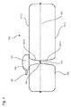
- Fig. 1 shows a schematic view of a liquid tank 100 for a motor vehicle.
- the liquid tank 100 is composed of a first liquid tank shell 111-1 and a second liquid tank shell 111-2, which are fluid-tightly welded together at the edge.
- the first liquid tank shell 111 - 1 has a first connection element 101 - 1 which extends from an inner wall 103 into the interior 105 of the liquid tank 100.
- the second liquid tank shell 111-2 has a second one Connecting element 101 - 2, which extends from an inner wall 103 of the liquid tank 100 into the interior 105 of the liquid tank 100.
- the liquid tank shells 111-1 and 111-2 are, for example, plastic moldings produced by injection molding.
- the plastics may include, for example, polyolefins such as polyethylene or polypropylene, polycarbonate, polystyrene, polyamide or polyoxymethylene (POM).
- the first and second connection elements 101-1 and 101-2 touch each other at a junction 107 and are connected to each other at this.
- the connection of the two connecting elements 101-1 and 101-2 can be realized by welding.
- the connecting elements 101-1 and 101-2 internally connect a bottom and top surfaces internally in the liquid tank 100 to each other and reduce deformation of the tank geometry at overpressure or underpressure, such as buckling or contraction.
- the connecting elements 101-1 and 101-2 are designed with a tubular geometry. In general, a plurality of connecting elements can also be arranged inside the liquid tank 100.
- the second connection element 101-2 comprises a passage opening 109 for the passage of a fluid.
- the fluid may be, for example, air, water or a fuel.
- the connecting elements 101-1 and 101-2 form a tie rod or connecting dome between both sides of the liquid tank 100. Since expansion of the liquid tank 100 is prevented by the connecting elements 101-1 and 101-2, it can be ensured that the passage opening 109 always is located at the intended position inside the liquid tank 100.
- a hood 127 is formed with a port 125, such as a ventilation port.
- the passage opening 109 is formed adjacent to the connection point 107 between the first and second connection elements 101-1 and 101-2. This allows the functions of the dip tube and a tie rod in a single multi-functional component summarize.
- a dip tube is formed, which serves to switch off a Be Davistlforung during refueling.
- the dip tube is thereby combined with the connecting elements 102-1 and 101-2.
- the projecting from above into the interior 105 of the liquid tank 100, tubular Connecting element 101-2 discharges the air displaced during filling from the liquid tank 100. If the rising liquid level overflows the passage opening 109, no further air can escape.
- the pressure in the remaining air bubble in the liquid tank 100 increases.
- the fluid in a filler pipe rises to the liquid tank 100 beyond the level of the liquid level in the liquid tank 100. This leads to a shutdown of the fuel nozzle without the liquid tank 100 is overcrowded. In this way, the liquid tank 100 is prevented from being filled beyond a predefined level
- Fig. 2 shows a schematic view of another embodiment of the liquid tank 100.
- the passage opening 109 adjacent to the inner wall 103 of the liquid tank 100 is formed.
- the passage opening 109 can be used for completely venting the liquid tank 100.
- a U-shaped channel 113 for a liquid closure is formed inside the connecting element 101-2. Gravity holds part of the liquid 129 in a lower part of the U-shaped channel 113, so that the liquid 129 forms a gas-tight seal.
- Fig. 3 shows a schematic view of another embodiment of the liquid tank 100.
- the connecting element 101-2 comprises a screen 115 for filtering the fluid. Through the screen 115 foreign bodies are retained, which are in fluid flow through the connecting element 101-2. In this way, another function can be integrated into the interior of the connecting element 101-2, resulting in even greater space savings.
- the second connection element 101-2 comprises a valve 117 for blocking a fluid direction.
- the valve 117 is, for example, a check valve or a check valve which allows the flow of the fluid in only one direction. In this way, the flow direction in the interior of the connecting element 101-2 can be controlled.
- Fig. 4 shows a schematic view of another embodiment of the liquid tank 100.
- the connection point 107 has a connection opening 119.
- the fluid, the through the passage opening 117 or exits, lead to the opposite side of the liquid tank 100.
- the passage opening 109 is formed in the region of the inner wall 103 of the liquid tank 100.
- the connecting element 101-2 may have a plurality of differently arranged passage openings.
- a passage opening may be arranged opposite another passage opening. In a blockage of a passage opening by a floating object in this case, the fluid can still flow through the other passage opening on the opposite side. As a result, for example, a fluid passage into the connecting element 102-1 can be ensured.
- a plurality of passage openings may be arranged in the longitudinal direction along the second connection element 101-2.
- the fluid can flow out of or into the liquid tank at any height.
- a non-shown float may be provided in the connector 101-2. The position of the float changes with the liquid level in the interior of the connecting element 101-2. This can be used, for example, for the float closing a vent opening arranged in the upper part of the connecting element 101-2 when a predetermined fill level in the liquid tank 100 is reached. Thereby, a float valve inside the liquid tank 100 can be realized.
- connecting elements 101-1 and 101-2 are also advantageous, since in this case tensile forces can be transmitted in a straight line between the walls of the liquid tank 100 without producing deformations in the connecting elements 101-1 and 101-2.
- Fig. 5 shows a schematic view of another embodiment of the liquid tank 100.
- the connecting element 101-2 is divided by a partition 121 into a left chamber 123-1 and a right chamber 123-2.
- the two chambers 123-1 and 123-2 are hermetically separated from each other by the partition wall 121.
- the left-hand chamber 123 - 1 comprises a first through-opening 109 - 1 for filling the liquid tank 100.
- the first through-opening 109 - 1 is arranged in the region of the lower inner wall 103 of the liquid tank 100. This will drain the fluid from Bottom filled in the liquid tank 100.
- the first passage opening 109-1 is usually below the liquid level, so that foaming and blistering during filling of the liquid tank 100 is prevented.
- the right-hand chamber 123-2 comprises a second through-opening 109-2 for venting the liquid tank 100.
- the second through-opening 109-2 is arranged in the region of the upper inner wall 103 of the liquid tank 100. As a result, the liquid tank 100 can be filled almost completely before a venting or float valve coupled to the second passage opening 109-2 prevents further outflow.
- the connecting elements 101-1 and 101-2 thus serve not only for the transmission of tensile forces, but at the same time both as a filler neck for refueling of the liquid tank 100 and as a dip tube of Be Pavllbellusterung to limit the maximum level.
- weight savings and space savings can be achieved.
- a compactification is particularly advantageous in cramped space in motor vehicles.
- a stable embodiment of the dip tube is achieved by bilateral mechanical connection between a bottom and a ceiling of the liquid tank. Since bending or warping of the wall of the liquid tank is prevented by the connecting members 101-1 and 101-2, the through hole 109 is always located at the intended position inside the liquid tank 100. Swelling or contraction of the liquid tank 100 is due to the direct support prevented at the passage opening 109 for the dip tube, so that the predetermined by the passage opening 109 Abschaltrise does not change in pressure fluctuations.
Abstract
Die vorliegende Erfindung betrifft einen Flüssigkeitstank (100) für ein Kraftfahrzeug, mit einem ersten Verbindungselement (101-1), das sich von einer Innenwandung (103) des Flüssigkeitstanks (100) in das Innere (105) des Flüssigkeitstanks (100) erstreckt; einem zweiten Verbindungselement (101-2), das sich von der Innenwandung (103) des Flüssigkeitstanks (100) in das Innere (105) des Flüssigkeitstanks (100) erstreckt und das an einer Verbindungsstelle (107) mit dem ersten Verbindungselement (101-2) verbunden ist, und einer Durchtrittsöffnung (109) zum Durchleiten eines Fluids, die in dem ersten oder zweiten Verbindungselement (101-1, 101-2) angeordnet ist.The present invention relates to a liquid tank (100) for a motor vehicle, comprising: a first connecting member (101-1) extending from an inner wall (103) of the liquid tank (100) into the interior (105) of the liquid tank (100); a second connecting element (101-2) extending from the inner wall (103) of the liquid tank (100) into the interior (105) of the liquid tank (100) and connected at a connection point (107) to the first connecting element (101-2 ), and a passage (109) for passing a fluid disposed in the first or second connection member (101-1, 101-2).
Description
Die vorliegende Erfindung betrifft einen Flüssigkeitstank für ein Kraftfahrzeug.The present invention relates to a liquid tank for a motor vehicle.
Bei Flüssigkeitstanksystemen kann im Inneren des Flüssigkeitstanks ein Tauchrohr mit einer Öffnung gebildet sein, durch die eine Flüssigkeit ab einem Erreichen eines bestimmten Pegels hindurchtritt. Das Tauchrohr ist an einer Wand des Flüssigkeitstanks befestigt. Dehnt sich der Flüssigkeitstank aus oder zieht sich der Flüssigkeitstank zusammen, wie beispielsweise bei unterschiedlichen Druckverhältnissen, so verändert sich die Lage der Öffnung im Inneren des Flüssigkeitstanks. Ein Flüssigkeitsstand kann in diesem Fall nicht mehr exakt erfasst werden.In liquid tank systems, a dip tube may be formed inside the liquid tank with an opening through which a liquid passes from reaching a certain level. The dip tube is attached to a wall of the liquid tank. If the liquid tank expands or if the liquid tank contracts, as for example under different pressure conditions, the position of the opening in the interior of the liquid tank changes. A liquid level can not be detected exactly in this case.
Es ist die der Erfindung zugrundeliegende Aufgabe, einen Flüssigkeitstank anzugeben, bei dem das Verändern der Lage einer Durchtrittsöffnung für ein Fluid verhindert wird, wie beispielweise bei einer Deformation des Flüssigkeitstanks bei erhöhtem Druck.It is the object underlying the invention to provide a liquid tank in which the changing of the position of a passage opening for a fluid is prevented, such as in a deformation of the liquid tank at elevated pressure.
Diese Aufgabe wird durch den Gegenstand mit den Merkmalen nach dem unabhängigen Anspruch gelöst. Vorteilhafte Ausführungsformen der Erfindung sind Gegenstand der Figuren, der Beschreibung und der abhängigen Ansprüche.This object is achieved by the subject matter having the features of the independent claim. Advantageous embodiments of the invention are the subject of the figures, the description and the dependent claims.
Gemäß einem Aspekt der Erfindung wird die Aufgabe durch einen Flüssigkeitstank für ein Kraftfahrzeug gelöst, mit einem ersten Verbindungselement, das sich von einer Innenwandung des Flüssigkeitstanks in das Innere des Flüssigkeitstanks erstreckt; einem zweiten Verbindungselement, das sich von der Innenwandung des Flüssigkeitstanks in das Innere des Flüssigkeitstanks erstreckt und das an einer Verbindungsstelle mit dem ersten Verbindungselement verbunden ist; und einer Durchtrittsöffnung zum Durchleiten eines Fluids, die in dem ersten oder zweiten Verbindungselement angeordnet ist. Das Fluid kann Luft oder eine Flüssigkeit sein. Dadurch wird beispielsweise der technische Vorteil erreicht, dass durch eine beidseitige mechanische Anbindung zwischen einem Boden und einer Decke des Flüssigkeitstanks ein Verbiegen einer Wandung des Flüssigkeitstanks verhindert wird, beispielsweise bei einem Verzug der Deckenfläche oder aufgrund von Gasdruck oder Eisdruck. Ein Aufblähen oder Zusammenziehen des Flüssigkeitstanks kann aufgrund der Verbindungselemente verhindert werden. Durch die in dem Verbindungselement angeordnete Durchtrittsöffnung kann beispielsweise eine Veränderung der Abschaltniveaus verhindert werden, das durch die Lage der Durchtrittsöffnung definiert wird. Durch die miteinander verbundenen Verbindungselemente und die Durchtrittsöffnungen kann beispielsweise eine stabile Ausführung eines Tauchrohres erzielt werden. Zudem wird eine Integration von Funktionen in wenige Bauteile und eine Gewichtersparnis erreicht. Daneben kann eine Platzersparnis durch kompakten Bauraum erzielt werden.According to one aspect of the invention, the object is achieved by a liquid tank for a motor vehicle, having a first connecting element which extends from an inner wall of the liquid tank into the interior of the liquid tank; a second connecting member extending from the inner wall of the liquid tank into the interior of the liquid tank and connected at a junction with the first connecting member; and a passage for passing a fluid disposed in the first or second connection member. The fluid may be air or a liquid. As a result, for example, the technical advantage is achieved that a bending of a wall of the liquid tank is prevented by a bilateral mechanical connection between a floor and a ceiling of the liquid tank, for example, in a delay of the ceiling surface or due to gas pressure or ice pressure. Swelling or contraction of the liquid tank can be prevented due to the connecting elements. By arranged in the connecting element passage opening, for example, a change in the shutdown levels can be prevented, which is defined by the position of the passage opening. Through the interconnected connecting elements and the passage openings can For example, a stable design of a dip tube can be achieved. In addition, an integration of functions into a few components and a weight saving is achieved. In addition, a space savings can be achieved by compact space.
In einer vorteilhaften Ausführungsform des Flüssigkeitstanks ist die Durchtrittsöffnung benachbart zu der Verbindungsstelle zwischen dem ersten und dem zweiten Verbindungselement angeordnet. Dadurch wird beispielsweise der technische Vorteil erreicht, dass die Durchtrittsöffnung im Inneren des Tanks liegt und sich die Stabilität im Bereich der Durchtrittsöffnung verbessert.In an advantageous embodiment of the liquid tank, the passage opening is arranged adjacent to the connection point between the first and the second connection element. As a result, for example, the technical advantage is achieved that the passage opening is located in the interior of the tank and improves the stability in the region of the passage opening.
In einer weiteren vorteilhaften Ausführungsform des Flüssigkeitstanks ist die Durchtrittsöffnung benachbart zu der Innenwandung des Flüssigkeitstanks angeordnet. Dadurch wird beispielsweise der technische Vorteil erreicht, dass der Flüssigkeitstank vollständig mit einer Flüssigkeit gefüllt werden kann, bevor diese durch die Durchtrittsöffnung hindurchtritt.In a further advantageous embodiment of the liquid tank, the passage opening is arranged adjacent to the inner wall of the liquid tank. As a result, for example, the technical advantage is achieved that the liquid tank can be completely filled with a liquid before it passes through the passage opening.
In einer weiteren vorteilhaften Ausführungsform des Flüssigkeitstanks ist innerhalb des zweiten Verbindungselementes ein U-förmiger Kanal für einen Flüssigkeitsverschluss gebildet. Dadurch wird beispielsweise der technische Vorteil erreicht, dass Dämpfe nicht aus dem Inneren des Flüssigkeitstanks entweichen können.In a further advantageous embodiment of the liquid tank, a U-shaped channel for a liquid closure is formed within the second connecting element. As a result, for example, the technical advantage is achieved that vapors can not escape from the interior of the liquid tank.
In einer weiteren vorteilhaften Ausführungsform des Flüssigkeitstanks weist das zweite Verbindungselement ein Sieb zum Filtern des Fluids auf. Dadurch wird beispielsweise der technische Vorteil erreicht, dass Fremdkörper eines Fluids, das durch die Durchtrittsöffnung hindurchtritt, zurückgehalten werden können und sich ein kompakter Aufbau des Flüssigkeitstanks bei einer weiteren Funktionsintegration ergibt.In a further advantageous embodiment of the liquid tank, the second connecting element has a filter for filtering the fluid. As a result, for example, the technical advantage is achieved that foreign bodies of a fluid that passes through the passage opening can be retained and results in a compact construction of the liquid tank in a further functional integration.
In einer weiteren vorteilhaften Ausführungsform des Flüssigkeitstanks weist das zweite Verbindungselement ein Ventil zum Sperren einer Fluidrichtung auf. Dadurch wird beispielsweise der technische Vorteil erreicht, dass der Durchtritt des Fluids richtungsmäßig gesteuert werden kann und sich ein kompakter Aufbau des Flüssigkeitstanks bei einer weiteren Funktionsintegration ergibt.In a further advantageous embodiment of the liquid tank, the second connecting element has a valve for blocking a fluid direction. As a result, for example, the technical advantage is achieved that the passage of the fluid can be directionally controlled and results in a compact construction of the liquid tank in a further functional integration.
In einer weiteren vorteilhaften Ausführungsform des Flüssigkeitstanks weist das zweite Verbindungselement eine Mehrzahl von Durchtrittsöffnungen auf. Dadurch wird beispielsweise der technische Vorteil erreicht, dass auch bei der Verstopfung einer Durchtrittsöffnung weitere Durchtrittsöffnungen zur Verfügung stehen.In a further advantageous embodiment of the liquid tank, the second connecting element has a plurality of passage openings. This will For example, the technical advantage achieved that even with the blockage of a passage opening further passage openings are available.
In einer weiteren vorteilhaften Ausführungsform des Flüssigkeitstanks liegt eine erste Durchtrittsöffnung der Mehrzahl von Durchtrittsöffnungen gegenüber einer zweiten Durchtrittsöffnung der Mehrzahl von Durchtrittsöffnungen. Dadurch wird beispielsweise der technische Vorteil erreicht, dass bei einer Verstopfung einer Durchtrittsöffnung durch einen schwimmenden Gegenstand auf der einen Seite des Verbindungselementes das Fluid noch durch die Durchtrittsöffnung auf der gegenüberliegenden Seite strömen kann.In a further advantageous embodiment of the liquid tank is a first passage opening of the plurality of passage openings with respect to a second passage opening of the plurality of passage openings. As a result, the technical advantage is achieved, for example, that with a blockage of a passage opening by a floating object on one side of the connecting element, the fluid can still flow through the passage opening on the opposite side.
In einer weiteren vorteilhaften Ausführungsform des Flüssigkeitstanks sind die Durchtrittsöffnungen entlang des zweiten Verbindungselementes angeordnet. Dadurch wird beispielsweise der technische Vorteil erreicht, dass das Fluid in jeder Höhe aus oder in den Flüssigkeitstank strömen kann.In a further advantageous embodiment of the liquid tank, the passage openings are arranged along the second connecting element. As a result, for example, the technical advantage is achieved that the fluid can flow out of or into the liquid tank at any height.
In einer weiteren vorteilhaften Ausführungsform des Flüssigkeitstanks ist das zweite Verbindungselement durch eine Trennwand in eine erste Kammer und eine zweite Kammer unterteilt. Dadurch wird beispielsweise der technische Vorteil erreicht, dass ein Aufbau mit unabhängigen Kammern erzielt wird, die jeweils mit Durchtrittsöffnungen für unterschiedliche Zwecke versehen sein können.In a further advantageous embodiment of the liquid tank, the second connecting element is divided by a partition into a first chamber and a second chamber. Thereby, for example, the technical advantage is achieved that a structure with independent chambers is achieved, which can be provided with openings for different purposes in each case.
In einer weiteren vorteilhaften Ausführungsform des Flüssigkeitstanks umfasst die erste Kammer eine erste Durchtrittsöffnung zum Befüllen des Flüssigkeitstanks und die zweite Kammer eine Durchtrittsöffnung zum Entlüften des Flüssigkeitstanks. Dadurch wird beispielsweise der technische Vorteil erreicht, dass sowohl eine Befüllung als auch eine Entlüftung innerhalb des gleichen Verbindungselementes realisiert wird und ein Aufbau noch weiter kompaktifiziert wird.In a further advantageous embodiment of the liquid tank, the first chamber comprises a first passage opening for filling the liquid tank and the second chamber has a passage opening for venting the liquid tank. As a result, for example, the technical advantage is achieved that both a filling and a vent within the same connecting element is realized and a structure is further compacted.
In einer weiteren vorteilhaften Ausführungsform des Flüssigkeitstanks umfasst das zweite Verbindungselement einen Schwimmer. Dadurch wird beispielsweise der technische Vorteil erreicht, dass sich der Füllstand innerhalb des Verbindungselementes ermitteln lässt.In a further advantageous embodiment of the liquid tank, the second connecting element comprises a float. As a result, for example, the technical advantage is achieved that the level can be determined within the connecting element.
In einer weiteren vorteilhaften Ausführungsform des Flüssigkeitstanks weist die Verbindungsstelle zum Durchleiten des Fluids zwischen dem ersten Verbindungselement und dem zweiten Verbindungselement auf. Dadurch wird beispielsweise der technische Vorteil erreicht, dass das Fluid zu einer entgegengesetzten Seite des Flüssigkeitstanks geleitet werden kann.In a further advantageous embodiment of the liquid tank, the connection point for passing the fluid between the first connection element and the second connection element. As a result, for example, the technical Advantage achieved that the fluid can be directed to an opposite side of the liquid tank.
In einer weiteren vorteilhaften Ausführungsform des Flüssigkeitstanks ist der Flüssigkeitstank aus einer ersten Flüssigkeitstankschale mit dem ersten Verbindungselement und einer zweiten Flüssigkeitstankschale mit dem zweiten Verbindungselement zusammengesetzt. Dadurch wird beispielsweise der technische Vorteil erreicht, dass der Flüssigkeitstank auf einfache Weise hergestellt werden kann.In a further advantageous embodiment of the liquid tank, the liquid tank is composed of a first liquid tank shell with the first connection element and a second liquid tank shell with the second connection element. As a result, for example, the technical advantage is achieved that the liquid tank can be produced in a simple manner.
In einer weiteren vorteilhaften Ausführungsform des Flüssigkeitstanks weist das erste oder das zweite Verbindungselement eine Zylinderform auf. Dadurch wird beispielsweise der technische Vorteil erreicht, dass die Verbindungselemente Zugkräfte übertragen können, ohne sich zu verformen.In a further advantageous embodiment of the liquid tank, the first or the second connecting element has a cylindrical shape. As a result, for example, the technical advantage is achieved that the connecting elements can transmit tensile forces without deforming.
Ausführungsbeispiele der Erfindung sind in den Zeichnungen dargestellt und werden im Folgenden näher beschrieben.Embodiments of the invention are illustrated in the drawings and will be described in more detail below.
Es zeigen:
- Fig. 1
- eine schematische Ansicht eines Flüssigkeitstanks;
- Fig. 2
- eine weitere schematische Ansicht eines Flüssigkeitstanks;
- Fig. 3
- eine weitere schematische Ansicht eines Flüssigkeitstanks;
- Fig. 4
- eine weitere schematische Ansicht eines Flüssigkeitstanks; und
- Fig. 5
- eine weitere schematische Ansicht eines Flüssigkeitstanks.
- Fig. 1
- a schematic view of a liquid tank;
- Fig. 2
- another schematic view of a liquid tank;
- Fig. 3
- another schematic view of a liquid tank;
- Fig. 4
- another schematic view of a liquid tank; and
- Fig. 5
- another schematic view of a liquid tank.
Die Flüssigkeitstankschalen 111-1 und 111-2 sind beispielsweise Kunststoffformteile, die im Spritzgussverfahren hergestellt sind. Die Kunststoffe können beispielsweise Polyolefine wie Polyethylen oder Polypropylen, Polycarbonat, Polystyrol, Polyamid oder Polyoxymethylen (POM) umfassen.The liquid tank shells 111-1 and 111-2 are, for example, plastic moldings produced by injection molding. The plastics may include, for example, polyolefins such as polyethylene or polypropylene, polycarbonate, polystyrene, polyamide or polyoxymethylene (POM).
Das erste und das zweite Verbindungselement 101-1 und 101-2 berühren sich an einer Verbindungsstelle 107 und sind an dieser miteinander verbunden. Die Verbindung der beiden Verbindungselemente 101-1 und 101-2 kann durch ein Verschweißen realisiert sein. Dadurch verbinden die Verbindungselemente 101-1 und 101-2 innerlich im Flüssigkeitstank 100 eine Boden- und die Deckfläche mechanisch miteinander und vermindern Deformationen der Tankgeometrie bei Über- oder Unterdruck, wie beispielsweise ein Ausbeulen oder Zusammenziehen. Die Verbindungselemente 101-1 und 101-2 sind mit einer rohrförmigen Geometrie ausgeführt. Im Allgemeinen können im Inneren des Flüssigkeitstanks 100 auch mehrere Verbindungselemente angeordnet sein. Daneben umfasst das zweite Verbindungselement 101-2 eine Durchtrittsöffnung 109 zum Hindurchtreten eines Fluids. Das Fluid kann beispielsweise Luft, Wasser oder ein Kraftstoff sein.The first and second connection elements 101-1 and 101-2 touch each other at a
Die Verbindungselemente 101-1 und 101-2 bilden einen Zuganker oder Verbindungsdom zwischen beiden Seiten des Flüssigkeitstanks 100. Da eine Ausdehnung des Flüssigkeitstanks 100 durch die Verbindungselemente 101-1 und 101-2 verhindert wird, kann sichergestellt werden, dass sich die Durchtrittsöffnung 109 stets an der vorgesehenen Position im Inneren des Flüssigkeitstanks 100 befindet. An der Oberseite des Flüssigkeitstanks 100 ist eine Haube 127 mit einem Anschluss 125 gebildet, wie beispielsweise einem Belüftungsanschluss. Die Durchtrittsöffnung 109 ist benachbart zu der Verbindungsstelle 107 zwischen dem ersten und dem zweiten Verbindungselement 101-1 und 101-2 gebildet. Dadurch lassen sich die Funktionen des Tauchrohrs und eines Zugankers in einem einzigen multi-funktionalen Bauteil zusammenfassen.The connecting elements 101-1 and 101-2 form a tie rod or connecting dome between both sides of the
Durch die Durchtrittsöffnung 109 in dem Verbindungselement 102-1 wird beispielsweise ein Tauchrohr gebildet, das zum Abschalten einer Befüllentlüftung beim Betanken dient. Das Tauchrohr wird dadurch mit den Verbindungselementen 102-1 und 101-2 kombiniert. Das von oben in das Innere 105 des Flüssigkeitstanks 100 hineinragende, rohrförmige Verbindungselement 101-2 führt die beim Befüllen verdrängte Luft aus dem Flüssigkeitstank 100 ab. Wenn der ansteigende Flüssigkeitsspiegel die Durchtrittsöffnung 109 überspült, kann keine weitere Luft mehr entweichen.Through the
In der Folge erhöht sich der Druck in der verbleibenden Luftblase im Flüssigkeitstank 100. Dadurch steigt das Fluid in einem Einfüllrohr zu dem Flüssigkeitstank 100 über das Niveau des Flüssigkeitsspiegels im Flüssigkeitstank 100 hinaus an. Dies führt zu einem Abschalten der Zapfpistole, ohne dass der Flüssigkeitstank 100 überfüllt wird. Auf diese Weise wird verhindert, dass der Flüssigkeitstank 100 über ein vordefiniertes Niveau hinaus gefüllt wirdAs a result, the pressure in the remaining air bubble in the
Zusätzlich umfasst das zweite Verbindungselement 101-2 ein Ventil 117 zum Sperren einer Fluidrichtung. Das Ventil 117 ist beispielsweise eine Rückschlagklappe oder ein Rückschlagventil, das die Strömung des Fluids in nur einer Richtung zulässt. Auf diese Weise lässt sich die Strömungsrichtung im Inneren des Verbindungselementes 101-2 steuern.In addition, the second connection element 101-2 comprises a
Die Durchtrittsöffnung 109 ist im Bereich der Innenwandung 103 des Flüssigkeitstanks 100 gebildet. Im Allgemeinen kann das Verbindungselement 101-2 eine Mehrzahl unterschiedlich angeordneter Durchtrittsöffnungen aufweisen. Beispielsweise kann im dem Verbindungselement 101-2 eine Durchtrittsöffnung gegenüber einer anderen Durchtrittsöffnung angeordnet sein. Bei einer Verstopfung der einen Durchtrittsöffnung durch einen schwimmenden Gegenstand kann in diesem Fall das Fluid noch durch die andere Durchtrittsöffnung auf der gegenüberliegenden Seite strömen. Dadurch lässt sich beispielsweise ein Flüssigkeitsdurchtritt in das Verbindungselement 102-1 sicherstellen.The
Weiter können mehrere Durchtrittsöffnungen in Längsrichtung entlang des zweiten Verbindungselementes 101-2 angeordnet sein. In diesem Fall kann das Fluid in jeder Höhe aus oder in den Flüssigkeitstank strömen. Daneben kann in dem Verbindungselement 101-2 ein nicht-gezeigter Schwimmer vorgesehen sein. Die Lage des Schwimmers verändert sich mit dem Flüssigkeitspegel im Inneren des Verbindungselementes 101-2. Dies kann beispielsweise dazu verwendet werden, dass der Schwimmer eine im oberen Teil des Verbindungselementes 101-2 angeordnete Entlüftungsöffnung bei Erreichen eines vorgegebenen Füllstandes im Flüssigkeitstank 100 verschließt. Dadurch kann ein Schwimmerventil im Inneren des Flüssigkeitstanks 100 realisiert werden.Further, a plurality of passage openings may be arranged in the longitudinal direction along the second connection element 101-2. In this case, the fluid can flow out of or into the liquid tank at any height. Besides, a non-shown float may be provided in the connector 101-2. The position of the float changes with the liquid level in the interior of the connecting element 101-2. This can be used, for example, for the float closing a vent opening arranged in the upper part of the connecting element 101-2 when a predetermined fill level in the
Vorteilhaft ist zudem eine Zylinderform der Verbindungselemente 101-1 und101-2, da in diesem Fall Zugkräfte geradlinig zwischen den Wandungen des Flüssigkeitstanks 100 übertragen werden können, ohne Verformungen in den Verbindungselementen 101-1 und 101-2 zu erzeugen.Also advantageous is a cylindrical shape of the connecting elements 101-1 and 101-2, since in this case tensile forces can be transmitted in a straight line between the walls of the
Die linke Kammer 123-1 umfasst eine erste Durchtrittsöffnung 109-1 zum Befüllen des Flüssigkeitstanks 100. Die erste Durchtrittsöffnung 109-1 ist im Bereich der unteren Innenwandung 103 des Flüssigkeitstanks 100 angeordnet. Dadurch wird die Flüssigkeit von Unten in den Flüssigkeitstank 100 eingefüllt. Bei diesem Prozess befindet sich die erste Durchtrittsöffnung 109-1 zumeist unterhalb des Flüssigkeitspegels, so dass eine Schaum- und Blasenbildung beim Befüllen des Flüssigkeitstanks 100 verhindert wird.The left-hand chamber 123 - 1 comprises a first through-opening 109 - 1 for filling the
Die rechte Kammer 123-2 umfasst eine zweite Durchtrittsöffnung 109-2 zum Entlüften des Flüssigkeitstanks 100. Die zweite Durchtrittsöffnung 109-2 ist im Bereich der oberen Innenwandung 103 des Flüssigkeitstanks 100 angeordnet. Dadurch kann der Flüssigkeitstank 100 nahezu vollständig befüllt werden, bevor ein mit der zweiten Durchtrittsöffnung 109-2 gekoppeltes Entlüftungs- oder Schwimmerventil ein weiteres Ausströmen verhindert.The right-hand chamber 123-2 comprises a second through-opening 109-2 for venting the
Die Verbindungselemente 101-1 und 101-2 dienen somit nicht nur zur Übertragung von Zugkräften, sondern gleichzeitig sowohl als Füllstutzen für eine Betankung des Flüssigkeitstanks 100 als auch als Tauchrohr der Befüllbelüftung zur Begrenzung des maximalen Füllstandes. Durch die Integration von mehreren Funktionen in die Verbindungselemente 101-1 und 101-2 kann eine Gewichtersparnis und Platzersparnis erzielt werden. Eine Kompaktifizierung ist insbesondere bei beengtem Bauraum in Kraftfahrzeugen vorteilhaft.The connecting elements 101-1 and 101-2 thus serve not only for the transmission of tensile forces, but at the same time both as a filler neck for refueling of the
Bei der Verwendung der Verbindungselemente 101-1 und 101-2 als Tauchrohr wird eine stabile Ausführung des Tauchrohres durch beidseitige mechanische Anbindung zwischen einem Boden und einer Decke des Flüssigkeitstanks erreicht. Da durch die Verbindungselemente 101-1 und 101-2 ein Verbiegen oder Verziehen der Wandung des Flüssigkeitstanks verhindert wird, befindet sich die Durchtrittsöffnung 109 stets an der vorgesehenen Position im Inneren des Flüssigkeitstanks 100. Ein Aufblähen oder Zusammenziehen des Flüssigkeitstanks 100 wird aufgrund der unmittelbaren Abstützung an der Durchtrittsöffnung 109 für das Tauchrohr verhindert, so dass sich das durch die Durchtrittsöffnung 109 vorgegebene Abschaltniveau bei Druckschwankungen nicht verändert.When using the connecting elements 101-1 and 101-2 as a dip tube, a stable embodiment of the dip tube is achieved by bilateral mechanical connection between a bottom and a ceiling of the liquid tank. Since bending or warping of the wall of the liquid tank is prevented by the connecting members 101-1 and 101-2, the through
Alle in Verbindung mit einzelnen Ausführungsformen der Erfindung erläuterten und gezeigten Merkmale können in unterschiedlicher Kombination in dem erfindungsgemäßen Gegenstand vorgesehen sein, um gleichzeitig deren vorteilhafte Wirkungen zu realisieren.All features explained and shown in connection with individual embodiments of the invention may be provided in different combinations in the article according to the invention, in order to simultaneously realize their advantageous effects.
Der Schutzbereich der vorliegenden Erfindung ist durch die Ansprüche gegeben und wird durch die in der Beschreibung erläuterten oder den Figuren gezeigten Merkmale nicht beschränkt.The scope of the present invention is given by the claims and is not limited by the features illustrated in the specification or shown in the figures.
- 100100
- Flüssigkeitstankliquid tank
- 101-1101-1
- Verbindungselementconnecting element
- 101-2101-2
- Verbindungselementconnecting element
- 103103
- Innenwandunginner wall
- 105105
- InneresInterior
- 107107
- Verbindungsstellejunction
- 109109
- DurchtrittsöffnungThrough opening
- 109-1109-1
- DurchtrittsöffnungThrough opening
- 109-2109-2
- DurchtrittsöffnungThrough opening
- 111-1111-1
- FlüssigkeitstankschaleLiquid tank shell
- 111-2111-2
- FlüssigkeitstankschaleLiquid tank shell
- 113113
- Kanalchannel
- 115115
- Siebscree
- 117117
- VentilValve
- 119119
- DurchtrittsöffnungThrough opening
- 121121
- Trennwandpartition wall
- 123-1123-1
- Kammerchamber
- 123-2123-2
- Kammerchamber
- 125125
- Anschlussconnection
- 127127
- HaubeHood
- 129129
- Flüssigkeitliquid
Claims (15)
Applications Claiming Priority (1)
| Application Number | Priority Date | Filing Date | Title |
|---|---|---|---|
| DE102013105522.2A DE102013105522A1 (en) | 2013-05-29 | 2013-05-29 | Liquid tank for a motor vehicle |
Publications (1)
| Publication Number | Publication Date |
|---|---|
| EP2808193A1 true EP2808193A1 (en) | 2014-12-03 |
Family
ID=50774658
Family Applications (1)
| Application Number | Title | Priority Date | Filing Date |
|---|---|---|---|
| EP14169386.1A Withdrawn EP2808193A1 (en) | 2013-05-29 | 2014-05-22 | Fluid tank for a motor vehicle |
Country Status (2)
| Country | Link |
|---|---|
| EP (1) | EP2808193A1 (en) |
| DE (1) | DE102013105522A1 (en) |
Citations (8)
| Publication number | Priority date | Publication date | Assignee | Title |
|---|---|---|---|---|
| US1072371A (en) * | 1912-03-07 | 1913-09-02 | Joe C Stone | Alarm device for gasolene-tanks. |
| US1448580A (en) * | 1922-03-15 | 1923-03-13 | Walter L Tresemer | Valve |
| EP0068473A1 (en) * | 1981-07-01 | 1983-01-05 | Gerhard KG | Pressure tank |
| EP1596057A2 (en) * | 2004-05-14 | 2005-11-16 | Mann+Hummel Gmbh | Fuel module |
| DE102009036911A1 (en) * | 2009-08-11 | 2011-02-17 | Magna Steyr Fuel Systems Gmbh | Fuel tank for motor vehicles with tie rods |
| US20120037638A1 (en) * | 2009-04-23 | 2012-02-16 | Inergy Automotive Systems Research (Societe Anonyme) | Plastic fuel tank with improved creep resistance and method for the manufacture thereof |
| WO2012066647A1 (en) * | 2010-11-17 | 2012-05-24 | 愛三工業株式会社 | Fuel tank and method for manufacturing same |
| EP2465662A2 (en) * | 2010-12-17 | 2012-06-20 | Yachiyo Industry Co., Ltd. | Method for coupling built-in components to each other in hollow container |
-
2013
- 2013-05-29 DE DE102013105522.2A patent/DE102013105522A1/en not_active Withdrawn
-
2014
- 2014-05-22 EP EP14169386.1A patent/EP2808193A1/en not_active Withdrawn
Patent Citations (8)
| Publication number | Priority date | Publication date | Assignee | Title |
|---|---|---|---|---|
| US1072371A (en) * | 1912-03-07 | 1913-09-02 | Joe C Stone | Alarm device for gasolene-tanks. |
| US1448580A (en) * | 1922-03-15 | 1923-03-13 | Walter L Tresemer | Valve |
| EP0068473A1 (en) * | 1981-07-01 | 1983-01-05 | Gerhard KG | Pressure tank |
| EP1596057A2 (en) * | 2004-05-14 | 2005-11-16 | Mann+Hummel Gmbh | Fuel module |
| US20120037638A1 (en) * | 2009-04-23 | 2012-02-16 | Inergy Automotive Systems Research (Societe Anonyme) | Plastic fuel tank with improved creep resistance and method for the manufacture thereof |
| DE102009036911A1 (en) * | 2009-08-11 | 2011-02-17 | Magna Steyr Fuel Systems Gmbh | Fuel tank for motor vehicles with tie rods |
| WO2012066647A1 (en) * | 2010-11-17 | 2012-05-24 | 愛三工業株式会社 | Fuel tank and method for manufacturing same |
| EP2465662A2 (en) * | 2010-12-17 | 2012-06-20 | Yachiyo Industry Co., Ltd. | Method for coupling built-in components to each other in hollow container |
Also Published As
| Publication number | Publication date |
|---|---|
| DE102013105522A1 (en) | 2014-12-04 |
Similar Documents
| Publication | Publication Date | Title |
|---|---|---|
| DE102011079091A1 (en) | Collector for a cooling fluid and heat exchanger | |
| EP3368366B1 (en) | Fuel container with inlet check valve | |
| EP3055156B2 (en) | Filler neck for a motor vehicle operating-liquid tank | |
| DE4121324C2 (en) | Fuel tank for a motor vehicle | |
| EP1878891B1 (en) | Vertically divided expansion tank for cooling fluid | |
| DE102010030456A1 (en) | vent valve | |
| EP3368365B1 (en) | Saddle tank with swash barrier | |
| DE102005053815A1 (en) | De-aeration unit for aerating and de-aerating e.g. liquid fuel tank, has supply port connected with activated carbon filter, and bypass line discharging fuel to de-aeration pipe, where throttle is provided in bypass line | |
| DE4100388C2 (en) | ||
| EP2808193A1 (en) | Fluid tank for a motor vehicle | |
| EP2842785A1 (en) | Commercial vehicle tank | |
| EP3433520B1 (en) | Purging and/or ventilation valve for an operating liquid container | |
| EP3199715B1 (en) | Overflow for a basin, in particular rinsing basin | |
| DE112018006349T5 (en) | MULTI-CHAMBER RESERVOIR FOR A MOTOR VEHICLE | |
| EP2883733B1 (en) | Tank system for a vehicle | |
| DE102008014579B4 (en) | A diesel fuel tank open ventilation system, a foreclosure for an open diesel fuel tank ventilation system, and a process for aeration and deaeration of a diesel fuel tank | |
| DE2148063A1 (en) | DEVICE FOR VENTILATION AND VENTILATION OF FUEL TANK FOR COMBUSTION ENGINE | |
| DE10233350B4 (en) | Container combination with a two-channel connection between the containers | |
| DE102005048696B4 (en) | Container with filter element | |
| DE102018217930A1 (en) | Tank for a hydraulic unit | |
| EP2165969B1 (en) | Tank armature device for a liquid containing tank of a cluster of tanks | |
| DE112015005298B4 (en) | Heat exchanger | |
| DE202013010174U1 (en) | Filling cup for humidifier and humidifier | |
| DE1932243U (en) | HEAT EXCHANGER FOR AIR CONDITIONING OF MOTOR VEHICLES. | |
| WO2024094472A1 (en) | Ventilation device and brake system |
Legal Events
| Date | Code | Title | Description |
|---|---|---|---|
| PUAI | Public reference made under article 153(3) epc to a published international application that has entered the european phase |
Free format text: ORIGINAL CODE: 0009012 |
|
| 17P | Request for examination filed |
Effective date: 20140522 |
|
| AK | Designated contracting states |
Kind code of ref document: A1 Designated state(s): AL AT BE BG CH CY CZ DE DK EE ES FI FR GB GR HR HU IE IS IT LI LT LU LV MC MK MT NL NO PL PT RO RS SE SI SK SM TR |
|
| AX | Request for extension of the european patent |
Extension state: BA ME |
|
| STAA | Information on the status of an ep patent application or granted ep patent |
Free format text: STATUS: THE APPLICATION IS DEEMED TO BE WITHDRAWN |
|
| 18D | Application deemed to be withdrawn |
Effective date: 20150604 |