EP3433520B1 - Purging and/or ventilation valve for an operating liquid container - Google Patents
Purging and/or ventilation valve for an operating liquid container Download PDFInfo
- Publication number
- EP3433520B1 EP3433520B1 EP17709051.1A EP17709051A EP3433520B1 EP 3433520 B1 EP3433520 B1 EP 3433520B1 EP 17709051 A EP17709051 A EP 17709051A EP 3433520 B1 EP3433520 B1 EP 3433520B1
- Authority
- EP
- European Patent Office
- Prior art keywords
- valve
- ventilation
- purging
- valve housing
- opening
- Prior art date
- Legal status (The legal status is an assumption and is not a legal conclusion. Google has not performed a legal analysis and makes no representation as to the accuracy of the status listed.)
- Active
Links
Images


Classifications
-
- F—MECHANICAL ENGINEERING; LIGHTING; HEATING; WEAPONS; BLASTING
- F16—ENGINEERING ELEMENTS AND UNITS; GENERAL MEASURES FOR PRODUCING AND MAINTAINING EFFECTIVE FUNCTIONING OF MACHINES OR INSTALLATIONS; THERMAL INSULATION IN GENERAL
- F16K—VALVES; TAPS; COCKS; ACTUATING-FLOATS; DEVICES FOR VENTING OR AERATING
- F16K24/00—Devices, e.g. valves, for venting or aerating enclosures
- F16K24/04—Devices, e.g. valves, for venting or aerating enclosures for venting only
- F16K24/042—Devices, e.g. valves, for venting or aerating enclosures for venting only actuated by a float
- F16K24/044—Devices, e.g. valves, for venting or aerating enclosures for venting only actuated by a float the float being rigidly connected to the valve element, the assembly of float and valve element following a substantially translational movement when actuated, e.g. also for actuating a pilot valve
-
- B—PERFORMING OPERATIONS; TRANSPORTING
- B60—VEHICLES IN GENERAL
- B60K—ARRANGEMENT OR MOUNTING OF PROPULSION UNITS OR OF TRANSMISSIONS IN VEHICLES; ARRANGEMENT OR MOUNTING OF PLURAL DIVERSE PRIME-MOVERS IN VEHICLES; AUXILIARY DRIVES FOR VEHICLES; INSTRUMENTATION OR DASHBOARDS FOR VEHICLES; ARRANGEMENTS IN CONNECTION WITH COOLING, AIR INTAKE, GAS EXHAUST OR FUEL SUPPLY OF PROPULSION UNITS IN VEHICLES
- B60K15/00—Arrangement in connection with fuel supply of combustion engines or other fuel consuming energy converters, e.g. fuel cells; Mounting or construction of fuel tanks
- B60K15/03—Fuel tanks
- B60K15/035—Fuel tanks characterised by venting means
- B60K15/03519—Valve arrangements in the vent line
-
- B—PERFORMING OPERATIONS; TRANSPORTING
- B60—VEHICLES IN GENERAL
- B60K—ARRANGEMENT OR MOUNTING OF PROPULSION UNITS OR OF TRANSMISSIONS IN VEHICLES; ARRANGEMENT OR MOUNTING OF PLURAL DIVERSE PRIME-MOVERS IN VEHICLES; AUXILIARY DRIVES FOR VEHICLES; INSTRUMENTATION OR DASHBOARDS FOR VEHICLES; ARRANGEMENTS IN CONNECTION WITH COOLING, AIR INTAKE, GAS EXHAUST OR FUEL SUPPLY OF PROPULSION UNITS IN VEHICLES
- B60K15/00—Arrangement in connection with fuel supply of combustion engines or other fuel consuming energy converters, e.g. fuel cells; Mounting or construction of fuel tanks
- B60K15/03—Fuel tanks
- B60K2015/03256—Fuel tanks characterised by special valves, the mounting thereof
- B60K2015/03289—Float valves; Floats therefor
Definitions
- the present invention relates to a vent and / or ventilation valve, which is also referred to as a shut-off valve, for an operating fluid container, and a working fluid container having an inventive vent and / or venting valve.
- An operating fluid container may, for example, be a fuel tank, in particular for diesel or gasoline, or a liquid tank for aqueous urea solution, which is required for a selective catalytic reduction (SCR) process. It is preferably a fuel tank whose wall is made of several layers. More preferably, the wall or outer wall of the working fluid container comprises a HDPE ( High Density Polyethylene ) . Also preferably, the operating fluid container is produced in the extrusion blow molding process. More preferably, the liquid container for an aqueous urea solution is produced by injection molding. Most preferably, the working fluid container is a liquid container for an aqueous urea solution, which may also be referred to as an SCR container. The SCR container is preferably produced by injection molding or by blow molding. The SCR container further preferably has a wall comprising HDPE. Most preferably, the SCR container has a single layer wall, especially of HDPE.
- SCR selective catalytic reduction
- a fuel tank wherein all embodiments are also generally applicable for operating fluid container.
- the operating fluid container is particularly preferably an SCR container.
- a venting and / or venting valve is sometimes referred to merely as a venting valve or shut-off valve.
- the fuel tank when filling a fuel tank with fuel, the fuel tank can be filled unhindered, located in the fuel tank air or located in the fuel tank air-gas mixture must be able to escape from the fuel tank, otherwise a pressure increase within the fuel tank would hinder the filling process , Therefore, for bleeding the fuel tank is usually provided in the fuel tank at least one vent valve.
- vent valves From the prior art known vent valves (see, eg FR 2 896 568 A1 . US 2003/0189110 A1 or US 5,711,339 ) comprise a hollow valve housing, which has at least one communication opening, by means of a valve housing interior is fluidly connected to the environment.
- valve housing interior When the vent valve is installed in a fuel tank, the valve housing interior is fluidly connected to the fuel tank interior via the communication port so as to permit exchange of fuel and a fuel vapor-air mixture between the fuel tank interior and the valve body interior via the communication port.
- vent valve having a straightforward and / or compact construction. Furthermore, it is desirable to provide a vent valve by which the concentration of the working fluid in the air-gas mixture escaping from the operating fluid container is reduced. It is also desirable to provide a vent valve, which leads to an improved feedback response to the refueling person when refueling the operating fluid container.
- vent valve vent and / or vent valve
- the vent valve according to the invention for a working fluid container has a housing with an upper part and a lower part.
- upper part, lower part and / or housing are made of plastic. More preferably, the upper part and the lower part are made of a compatible plastic, as will be explained below. Most preferably, the top and / or bottom are made of HDPE.
- the housing is in two parts.
- upper part and lower part form the housing after their connection. This advantageously makes it possible to provide a vent valve which can be produced easily and efficiently.
- the lower part can be connected to the upper part such that the housing has a receiving volume which is delimited by a partition wall formed between the upper part and the lower part.
- connection of the upper part to the lower part may be any suitable connection.
- Such a connection is preferably a form-fitting, non-positive, and / or cohesive connection.
- Cohesive connections can be achieved for example by gluing, preferably welding.
- a frictional connection can be achieved, for example and preferably, by at least partially inserting or inserting the lower part into the upper part, wherein the upper and lower part are selected such that an elastic deformation of upper part and / upper part takes place.
- the upper part can be inserted or inserted into the lower part.
- a positive connection can be achieved for example via locking lugs and / or corresponding receptacles on upper part and / or lower part, which engage in the insertion.
- the receiving volume is preferably a receiving volume for receiving operating fluid contained in the escaping air-gas mixture.
- Such operating fluid contained in the exiting air-gas mixture is also referred to as liquid carry-over .
- the receiving volume is preferably a receiving volume for receiving liquid carry-over.
- the uptake volume has a size of ⁇ 20 and ⁇ 40 ml, more preferably ⁇ 25 and ⁇ 35 ml. Most preferably, the uptake volume has a size of about 30 ml. It has surprisingly been found that with such sizes selected of the receiving volume, in particular an effective separation with aqueous urea solution (SCR) is ensured. Even more preferably, the specified sizes of the receiving volume without consideration of possibly arranged in the receiving volume droplet apply.
- SCR aqueous urea solution
- the partition is formed in connection of the lower part with the upper part and limits the receiving volume of the housing.
- the partition wall may preferably be formed by a wall of the upper part and / or the lower part. Particularly preferably, the partition is formed by the lower part, or its wall. More preferably, the partition is made of plastic.
- the partition wall preferably has a substantially planar and / or planar configuration, it is configured, for example, and preferably dish-shaped. In other words, the partition wall contains substantially no steps or gradations. It also preferably has a curvature, as will be described in detail below.
- the lower part of the venting valve according to the invention has at least a first valve housing with a first valve housing interior and a second valve housing with a second valve housing interior, wherein in the first valve housing interior, a first valve body and in the second valve housing interior, a second valve body is arranged variable in position.
- the first and second valve housing is preferably formed substantially hollow cylindrical and has a lateral surface which surrounds the valve housing interior. Furthermore, the first and second valve housing has a first and a second communication opening for fluid exchange between the first and second valve housing and an operating fluid container interior. Preferably, the first or the second communication opening is not arranged in the lateral surface of the first or second valve housing. More preferably, the first and the second communication opening is arranged on the end face of the valve housing, which faces away from the partition wall. Most preferably, the first and the second communication opening on the end face of the valve housing corresponds to the opening of a hollow cylinder.
- the at least two valve housings are arranged with respect to their longitudinal extent substantially parallel to each other.
- the lower part and the at least two valve housing are made in one piece.
- the first and second valve body may be any suitable valve body. It is particularly preferred that first and / or second valve body to a cup-shaped hollow body. More preferably, the first and / or second valve body is a float.
- first and / or the second valve body is arranged variable in position within the respective valve housing interior, wherein the longitudinal extent of the first and / or second valve body is arranged parallel to the longitudinal extent of the first and second valve housing.
- the first and / or the second valve body is centered by means of at least one spacer within the respective valve housing interior.
- the spacer is advantageously still a freezing of the valve body in the valve housing interior effectively avoided. This is enormous advantageous, especially with aqueous urea solution as operating fluid.
- the at least one spacer can take any suitable configuration by which its function is ensured. Accordingly, the spacer may be formed, for example, as a projection, a nose, or a pin which extends away from the connected component. However, it is also possible that the at least one spacer has the shape of a arranged on the surface of the component continuous or partially interrupted ridge. The at least one spacer is always arranged on one of the two components such that it projects into the space between this connected component and the component to be contacted.
- the at least one spacer may be attached to the valve body and / or the valve housing, wherein a single spacer is connected to only one of the two components and never with both components simultaneously. More specifically, the at least one spacer is disposed on the envelope of the valve housing and / or the valve body. Preferably, the at least one spacer is arranged on the valve body. As a result, a greatly simplified production of the valve body is made possible by means of the injection molding process. Therefore, the valve body and the at least one spacer are particularly preferably produced in one piece.
- an improved relative movement of the valve body to its respective valve housing is advantageously ensured, since the two components only contact via the at least one spacer and thus the contact area between the components is minimized.
- This minimized contact surface minimizes at the same time the surface which can be wetted with operating fluid and which, upon freezing of this operating fluid, can lead to a loss of mobility of the two movable components relative to each other. Thus, either a freezing of the two components is prevented with each other, or minimizes the force required to release such a compound.
- the first and / or the second valve body is centered within the respective valve housing interior by means of at least two, preferably three, equiangularly spaced spacers.
- the angular distance of the spacers which are arranged on the envelope of the valve housing, or valve body, in plan view of the end face of the valve housing or the valve body 180 ° (two spacers), or 120 ° (three spacers).
- this seal is a seal made of an elastomer.
- a first vent opening is arranged, by means of which the receiving volume and the first valve housing interior are fluid-connectable. Furthermore, a second ventilation opening is arranged in the partition, by means of which the receiving volume and the second valve housing interior are fluid-connectable.
- the first and / or the second vent opening is designed as a valve seat, which can be closed by the first and second valve body, particularly preferably by a seal arranged on the valve body.
- the first or the second ventilation opening can be closed by the valve body on the valve body side.
- the first ventilation opening has a greater clearance than the second ventilation opening.
- the first ventilation opening must have a clear width of ⁇ 4 mm and the second ventilation opening must have a clear width of ⁇ 0.5 mm and ⁇ 4 mm to ensure effective function of the vent valve.
- the clear width of the second ventilation opening ⁇ 0.8 mm and ⁇ 1.2 mm and the clear width of the first ventilation opening ⁇ 6 mm, more preferably ⁇ 6 mm and ⁇ 15 mm, more preferably ⁇ 6 mm and ⁇ 15 mm.
- the clear width of the first vent is 8 to 12 times, more preferably 10 times the clear width of the second vent. It has surprisingly been found that such a relation between the two clear widths of the ventilation openings resulted in a particularly effective function of the ventilation valve according to the invention.
- the housing of the venting valve according to the invention has, especially when the lower part is connected to the upper part, a longitudinal extent. Along this longitudinal extent, the housing has a height, i. a housing height. This is preferably the case when the bleeder valve according to the invention is installed as intended in a working fluid container and this, more preferably, was installed in a vehicle.
- the first ventilation opening and the second ventilation opening of the ventilation valve according to the invention are arranged with respect to the longitudinal extent of the housing substantially in a same housing height. In other words, this means that the exact positioning of the first or second ventilation opening is essentially dependent on the design of the partition wall. Since, as described above, the partition wall preferably has a substantially planar and / or planar configuration, the two ventilation openings are also preferably located in this plane. If, on the other hand, the dividing wall has the preferred curvature, then the height in which the first ventilation opening is arranged can slightly deviate from that in which in which the second ventilation opening is arranged.
- the difference between the height of the first and the second ventilation opening is preferably ⁇ 4%, more preferably ⁇ 2% of the housing height. For example, in the latter case, with a housing height of 10 cm, the two ventilation openings are apart with respect to their height ⁇ 0.2 cm.
- the arrangement according to the invention of the two ventilation openings in a substantially identical housing height has, inter alia, the advantage that a particularly easy production of the venting valve is ensured, especially when the injection molding method is used.
- the upper part has at least one outlet opening.
- the outlet opening in this case breaks through the wall of the upper part and constitutes a fluid connection to the surroundings.
- the upper part has at least two, more preferably exactly two, outlet openings.
- the at least one outlet opening has an overpressure and / or vacuum valve.
- the upper part has at least two outlet openings, one of which has a pressure relief valve and the other a vacuum valve.
- the pressure relief valve and / or the vacuum valve is designed as umbrella mushroom valve. More preferably, the vacuum valve has an opening pressure of ⁇ -10 mbar, more preferably ⁇ -50 mbar and ⁇ -2 mbar, more preferably ⁇ -35 mbar and ⁇ -15 mbar, still more preferably about -20 mbar.
- the pressure relief valve preferably has an opening pressure of ⁇ 2 mbar, more preferably m 2 mbar and ⁇ 30 mbar, more preferably ⁇ 5 mbar and ⁇ 20 mbar, more preferably about 10 mbar.
- the aforementioned opening pressures showed a particularly effective function, in particular in the case of a venting valve for an SCR container.
- the first valve housing of the present invention has a continuous lateral surface.
- the lateral surface of the first valve housing is not pierced through openings and is thus only via the first communication opening with the operating fluid container interior in connection.
- the second valve housing of the present invention at least a third communication opening for fluid exchange between the second valve housing interior and the operating fluid container interior.
- the second valve housing has at least one third communication opening in addition to the second communication opening.
- the third communication port may have any configuration that allows it to function properly. More preferably, the third communication opening is slit-shaped. More preferably, the third communication opening has a size of ⁇ 10 mm 2 , more preferably ⁇ 10 mm 2 and ⁇ 30 mm 2 , more preferably ⁇ 17 mm 2 and ⁇ 21 mm 2 and most preferably approximately ⁇ 19 mm 2 .
- These preferred sizes also surprisingly showed a particularly effective function of the venting valve according to the invention, in particular in the case of an operating fluid container for aqueous urea solution.
- the third communication opening is located with respect to the longitudinal extent of the housing substantially in a housing height, that the upper end of the communication opening is arranged according to the intended installation of the vent valve according to the invention in a working fluid container below the inside of the upper wall of the operating fluid container. This advantageously ensures that when refueling the operating fluid container always a free volume between the inside of the top wall and the operating fluid level remains.
- the upper part can preferably be positively and / or non-positively, or materially connected to the lower part.
- the housing of the venting valve according to the invention can first be assembled by a positive and / or frictional connection between the upper part and lower part before it is inserted into the operating fluid container, preferably in an opening in the wall of the operating fluid container.
- a material connection preferably a welded connection between the upper part and the lower part and preferably between the upper part, the lower part and the operating fluid container can be produced.
- the cohesive connection is particularly preferably made with the wall, more preferably the outer wall, of the operating fluid container.
- the upper part, the lower part and the operating fluid container are cohesively and preferably fluid-tight and cohesively connectable to each other.
- the positive and / or non-positive, or cohesive connection between the upper and lower part is fluid-tight.
- the upper part and a lower part having housing of the vent valve according to the invention, in particular in the connection region of the upper part and lower part has a continuous lateral surface.
- the liquid contained in the operating fluid container Fluid operating fluid, air and / or gas-air mixture
- the cohesive connection between upper part, lower part and operating fluid container after insertion of the vent valve in an operating fluid container and producing a cohesive connection fluid-tight.
- the upper part and the lower part at least in the region of the cohesive connection of compatible plastics.
- a compatible plastic should be understood to mean that a cohesive connection between the plastic of the upper part and the plastic of the lower part can be produced in particular by welding.
- the expert is in this regard a variety of plastic compounds known that can be welded together.
- the two plastics may be polyethylenes, preferably HDPE.
- Particularly preferred for compatible plastics are two identical plastics.
- the upper part and the lower part at least in the region of the cohesive connection of a plastic, which is compatible with the plastic of the operating fluid container, in particular the wall of the operating fluid container.
- a plastic which is compatible with the plastic of the operating fluid container, in particular the wall of the operating fluid container.
- a mist eliminator is preferably arranged within the receiving volume.
- the droplet separator serves to separate operating fluid from the air-gas mixture ( liquid carry-over ) .
- the mist eliminator uses the higher inertia of the liquid droplets of the working fluid against the lower inertia of the gas carrying them.
- the moist air-gas mixture is guided through internals of the droplet, in which the flow direction of the moist air-gas mixture is at least once, preferably repeatedly deflected.
- the drops of liquid can not follow these changes in direction, which is why these bounce on the internals and settle there. With increasing deposition of the drops flow down and are thus collected in the receiving volume.
- the mist eliminator is preferably one or more baffles, preferably those having a plurality of elements, such as corners, creases or curves, which lead to a change in direction of the air-gas mixture flowing past the baffle surface. More preferably, the mist eliminator, or baffle, has a labyrinthine, i. angled, construction.
- the mist eliminator consists of a plastic, preferably a HDPE. Also preferably, the mist eliminator consists of the same plastic as the upper part and / or the lower part.
- the droplet is part of the upper part and / or the lower part, in particular it is preferably integrally formed with the upper part and / or the lower part. Accordingly, either the upper part or the lower part, as well however, the upper part and the lower part also preferably have elements or parts of the at least one droplet separator. When assembling the upper part with the lower part, the at least one droplet separator is then advantageously formed automatically.
- the droplet eliminator does not have to be used as a further component before connecting the upper part and the lower part, but is formed automatically and correctly positioned by connecting the upper part and the lower part.
- the mist eliminator with labyrinthine structures is made integral with the top and bottom.
- this allows a particularly simple production, a simple placement and an exact positioning can be ensured, wherein the labyrinth-like structures protrude from above and from below into the receiving volume.
- the accumulating in the receiving volume operating fluid is preferably returned to the interior of the operating fluid container. This is preferably carried out via the first ventilation opening and / or second ventilation opening in the dividing wall. More preferably, the return takes place via the first vent in the partition wall, since this has a greater clearance than the second vent.
- the partition is at least partially curved away from the receiving volume away.
- the dividing wall is arched concavely at least in regions toward the receiving volume.
- such a curved region is located at least in the region of the first ventilation opening and / or the second ventilation opening, preferably in the region of the first ventilation opening.
- the partition over its entire extent to a substantially uniform curvature.
- the vent valve according to the invention further comprises at least one securing device for securing the arrangement of the first valve body in the first valve housing interior and / or the second valve body in the second valve housing interior.
- the securing device does not seal the first communication opening of the first valve housing and / or the second communication opening of the second valve housing in a fluid-tight manner, but in a manner that prevents the valve bodies located therein from slipping out.
- a safety device can be provided, for example, in a simple manner by means of a cap placed on the valve housing with openings for the fluid exchange.
- the securing device is designed as a cap, in particular as a made of plastic - and more preferably by injection molding - produced cap. More preferably, the securing device can be placed or plugged onto the first valve housing and / or on the second valve housing. Also preferably, the securing device is non-positively and / or positively connected to the lower part, or the first and / or the second valve housing. For this purpose, preferably the securing device and / or the lower part, or the first and / or the second valve housing, a connecting means, for example, at least a latching nose which engages in a corresponding recess. Likewise preferred after such a placement or plugging no further connection means are necessary. Most preferably, the connecting means is made in one piece with the lower part, or the first and / or the second valve housing and / or the securing device.
- the securing device openings for the fluid exchange between the operating fluid container interior and a valve housing interior.
- the securing device is a cap which is placed simultaneously on the first and the second valve housing.
- the vent valve according to the invention further comprises at least one covering device for covering and / or for protecting the upper part.
- at least one covering device for covering and / or for protecting the upper part.
- the covering is designed as a cap, in particular as a plastic - and more preferably by injection molding - produced cap.
- the plastic used for the covering device is preferably HDPE, more preferably a two-component material (2K material).
- the two-component material preferably has a core of HDPE and an outer layer of polyamide surrounding this core.
- the HDPE advantageously ensures the possibility of welding the cover unit to a compatible material (for example the upper part of the venting valve), the outer layer of polyamide advantageously prevents permeation.
- the covering device can be placed or plugged onto the region of the upper part which is not arranged in the operating fluid container interior when the venting valve is installed in the operating fluid container as intended.
- the covering is non-positively, materially and / or positively connected to the upper part.
- the covering device and / or the upper part have a connecting means, for example at least one locking lug, which engages in a corresponding recess.
- the connecting means is made integral with the top and / or the cover. A welding of the covering device with the upper part is possible and, as described above, in a covering device made of HDPE or 2k material advantageous.
- the covering means openings for the fluid exchange with the environment.
- the covering device can furthermore be connectable to an activated carbon filter. This is particularly advantageous for working fluid containers containing gasoline, for example fuel tanks.
- the present invention also relates to an operating fluid container having the inventive and previously described vent valve. Accordingly, all features previously described for the vent valve apply as it were for the operating fluid container.
- the venting valve according to the invention is fluid-tightly connected to the wall of the operating fluid container. More preferably, the vent valve is in this case connected to the outer wall of the operating fluid container.
- the fluid-tight connection may also be, for example and preferably, a bonded connection.
- the venting valve according to the invention is in this case welded to the wall, or the outer wall, of the operating fluid container.
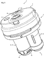
- FIG. 1 shows a schematic view of the vent valve (1) according to the invention for an SCR container, which has a housing (2), which consists of an upper part (3) and a lower part (4) connected thereto.
- the upper part (3) is non-positively and positively in the view shown with the Lower part (4) connected and ready for installation in an SCR container, with its outer wall, it is welded to produce a cohesive and fluid-tight connection.
- the upper part (3), as well as the lower part (4) were produced by injection molding of a HDPE.
- the upper part (3) has two outlet openings (60) which are designed as a pressure relief valve, as well as a vacuum valve and constitute a fluid connection to the environment (94).
- outlet openings (60) are designed as a pressure relief valve, as well as a vacuum valve and constitute a fluid connection to the environment (94).
- umbrella mushroom valves were used to close the outlet openings (60).
- the pressure relief valve has an opening pressure of about 10 mbar
- the vacuum valve has an opening pressure of about -20 mbar.
- the upper part (3) furthermore has a plurality of latching lugs (81), which are used to connect the upper part (3) to a cover device (not in FIG Fig. 1 shown) serve.
- the lower part (4) has two substantially hollow cylindrical valve housing, namely a first valve housing (42) and a second valve housing (45), wherein the first valve housing (42) has a first lateral surface (61) and the second valve housing (45) a second lateral surface (62).
- Both valve housings (42,45), or their interiors each have at least one communication opening (not in Fig. 1 but hidden by the securing device (80), which serve for fluid exchange with the operating fluid container interior.
- These communication ports are at the in FIG. 1 illustrated underside of the arranged two valve housing and correspond substantially to the end faces of the two hollow cylindrical valve housing designed.
- the lateral surface (61) of the first valve housing (42) is designed to be continuous and has no openings or openings.
- the lateral surface (62) of the second valve housing (45) has a slot-shaped further communication opening (63), via which the second valve housing (45), or its interior is fluidly connected to the interior of the operating fluid container.
- This third communication opening (63) has a size of about 19 mm 2 .
- FIG. 1 Furthermore, it can be seen a securing device (80), which is designed in the form of a cap made of a plastic, which is attached to the lower part (4) and a sliding out of the two in the valve housings (42,45) arranged valve body (not shown) prevented ,
- the cap (80) was produced by injection molding and is fastened to the lower part (4) via a plurality of latching noses (81) which are produced in one piece by injection molding with the lower part (4).
- FIG. 2 shows a schematic view of the injection-molded base (4) of the vent valve (1) according to the invention, wherein FIG. 2A facing the top and FIG. 2B with view towards the bottom of the lower part (4) is executed.
- baffles (71) are part of the Tropfenabscheiders (70) of the invention Serve bleed valve (1).
- first ventilation opening (51) and the second ventilation opening (52) can be seen, by means of which the later-formed receiving volume (31) and the first or second valve housing interior (43, 46) can be fluidly connected to one another.
- the two circular vents (51,52) are in the top of the in FIG. 2A shown lower parts (4), more precisely arranged in the partition wall (41).
- the clear width of the first ventilation opening (51) is greater than that of the second ventilation opening (52). More specifically, the inside width of the second vent (52) is about 1 mm, while the inside width of the first vent (51) is about 10 mm.
- the lower part (4) has a first and a second valve housing (42, 45), which in turn each have a lateral surface (61, 62). Only the lateral surface of the second valve housing (62) has a further communication opening (63), which is designed slot-shaped.
- the first valve housing (42) has a first communication opening (48) and the second valve housing (45) has a second communication opening (49) each having a fluid exchange between the first and second valve housing interior (43,46) and the not shown Allow operating fluid container interior (91).
- FIG. 2B represented view of the lower part (4), the two valve body (44,47) can be seen, the positionally variable in the two hollow cylindrical valve housings (42,45), and their interiors (43,46) are arranged.
- the first, as well as the second valve body (44,47) is made as a cup-shaped hollow body made of a plastic and has a total of six spacers (53) for centering the valve body in the valve housing interior (43,46), wherein in each case three of the six spacers ( 53) are arranged at an angular distance of 120 ° on the envelope of the valve body.
- FIG. 3 shows a schematic view of the injection-molded upper part (3) of the vent valve (1) according to the invention, wherein FIG. 3A facing the top and FIG. 3B is designed with a view towards the underside of the upper part (3).
- FIG. 3A again two of the plurality of detents (81), which were made in one piece with the upper part (3) and serve for non-positive and positive connection of the upper part (3) with the cover (82).
- FIG. 3B also shows the two outlet openings (60), as well as the screen mushroom valves arranged therein, which close these outlet openings (60) to provide a pressure relief valve, or a vacuum valve.
- baffles (71) are shown, which have a circular segment-like configuration and - as well as the Baffles (71) of the lower part (4) - serve as part of the Tropfenabscheiders (70) of the venting valve (1).
- the baffles (71) of the upper part (3) are also formed integrally with the upper part (3).
- FIG. 4 shows a further schematic view of the venting valve according to the invention (1) but this still has a plugged covering device (82).
- the covering device (82) designed as a cap consists of plastic and is securely connected to the latter via the latching lugs (81) of the upper part (3), but without preventing the fluid exchange with the environment (94).
- FIG. 5 shows a schematic view of a longitudinal section through the operating fluid container according to the invention (90), wherein the inventive vent valve (1), which is connected by welding material fit with the outer wall (93) of the wall (92) of the SCR container (90).
- the inventive vent valve (1) which is connected by welding material fit with the outer wall (93) of the wall (92) of the SCR container (90).
- the materials of the upper part (3), the lower part (4) and the outer wall (93) of the operating fluid container (90) together and enter into a material connection.
- the materials of the three aforementioned elements must be made of compatible plastics consist. In the present case these consist of HDPE. This advantageously ensures a particularly fluid-tight and at the same time the secure connection.
- the partition (41) which is formed integrally with the lower part (4) and in the connection of the upper part (3) and the lower part (4) limits a receiving volume (31), which for receiving from the escaping air Gas mixture contained operating fluid is suitable.
- the receiving volume (31) has a size of about 30 ml.
- this partition is plate-shaped, ie it has no steps or gradations, but has a substantially planar or planar configuration. Furthermore, the FIG. 5 it can be seen that the partition (41) over its entire extent a slight and substantially uniform curvature, which points away from the receiving volume (31).
- the two ventilation openings (51, 52) Arranged in the dividing wall (41) are also the two ventilation openings (51, 52) of the first and second valve housings (42, 45), which break through the dividing wall (41) and thus the receiving volume (31) with the first valve housing interior (43), or the second valve housing interior (46) fluidly connect.
- the two ventilation openings (51, 52) furthermore have valve seats (55), which are described below.
- valve bodies (44,47) which are designed as cup-shaped hollow bodies in the direction of the ventilation openings (51, 52). These cooperate with the valve seats (55) and safely and efficiently close the vent holes (51, 52) in the dividing wall (41) when the valve bodies (44, 47) are sufficiently raised by a rising working fluid level.
- first communication opening (48), or the second communication opening (49) On the end face of the first valve housing (42), or the second valve housing (45) is the first communication opening (48), or the second communication opening (49). A fluid exchange between the two valve housing interior spaces (43, 46) with the operating fluid container interior (91) is achieved via these two communication openings (48, 49).
- patch safety device (80) which prevents the two valve body (44,47) from sliding out of the valve housing interior (43,46).
- vent valve (1) according to the invention has a longitudinal extent (L), as well as with respect to this longitudinal extent (L) resulting housing height (h).
- the operating fluid When refueling the operating fluid container (90), the operating fluid enters the operating fluid container interior (91) and displaces as it rises the air therein, or the air-gas mixture therein.
- the thus displaced volume of the air or of the air-gas mixture initially enters the two valve housing internal spaces (43, 46) via the openings in the securing device (80) and the first and second communication openings (48, 49). It then flows within the two valve housing interior spaces (43, 46) past the two valve bodies (44, 47) and leaves the lower part (4) of the ventilation valve (1) via the two ventilation openings (51, 52) located in the partition wall (41). ,
- the displaced air-gas mixture After leaving the lower part (4), the displaced air-gas mixture enters the receiving volume (31) and is deflected several times by means of the labyrinth-like structures of the droplet separator (70) arranged therein, wherein the operating liquid contained in the air-gas mixture the impact surfaces (71) of the droplet separator (70) is deposited and runs down to this in the direction of the partition wall (41).
- the partition wall (41) As a result, leakage of operating fluid from the operating fluid container interior (91) into the environment (94) is effectively avoided in an advantageous manner.
- the volume of gas displaced from the working liquid container interior (91) after separation from the working liquid accumulates in the receiving volume (31) until the opening pressure of approximately 10 mbar of the pressure relief valve in one of the two outlet openings (60) is reached and the displaced one Gas volume is discharged into the environment (94).
- the pressure in the operating fluid container interior (91) decreases because operating fluid is removed. If the opening pressure of about -20 mbar is reached, then the vacuum valve in the other of the two outlet openings (60) open and air from the environment (94) flows for pressure equalization in the operating fluid container interior (91).
- the operating fluid separated as described above then passes through the first or second ventilation opening (51, 52) through the two valve housing interior spaces (43, 46) and the communication openings (51, 52) back into the operating fluid container interior (91). This is further facilitated by the fact that the dividing wall (41) is concavely curved towards the receiving volume (31) and thus the separated operating liquid can more easily reach the two ventilation openings (51, 52) arranged in the dividing wall (41).
- the first valve body (44) is first changed in its position and raised so that finally the seal (54) seals the valve seat (55) and thus the first ventilation opening (51). closes.
Description
Die vorliegende Erfindung betrifft ein Ent- und/oder Belüftungsventil, das auch als Abschaltventil bezeichnet wird, für einen Betriebsflüssigkeitsbehälter, sowie einen Betriebsflüssigkeitsbehälter aufweisend ein erfindungsgemäßes Ent- und/oder Belüftungsventil.The present invention relates to a vent and / or ventilation valve, which is also referred to as a shut-off valve, for an operating fluid container, and a working fluid container having an inventive vent and / or venting valve.
Ein Betriebsflüssigkeitsbehälter kann beispielsweise ein Kraftstoffbehälter, insbesondere für Diesel oder Benzin, oder ein Flüssigkeitsbehälter für wässrige Harnstofflösung sein, die für ein SCR-Verfahren (Selectiv Catalytic Reduction) benötigt wird. Bevorzugt handelt es sich um einen Kraftstoffbehälter, dessen Wand mehrschichtig ausgeführt ist. Noch bevorzugter umfasst die Wand oder Außenwand des Betriebsflüssigkeitsbehälters ein HDPE (High Density Polyethylen). Ebenfalls bevorzugt ist der Betriebsflüssigkeitsbehälter im Extrusionsblasformverfahren hergestellt. Weiter bevorzugt ist der Flüssigkeitsbehälter für eine wässrige Harnstofflösung im Spritzgussverfahren hergestellt. Am bevorzugtesten handelt es sich bei dem Betriebsflüssigkeitsbehälter um einen Flüssigkeitsbehälter für eine wässrige Harnstofflösung, der auch als SCR-Behälter bezeichnet werden kann. Der SCR-Behälter wird bevorzugt im Spritzgussverfahren oder im Blasformverfahren hergestellt. Der SCR-Behälter weist weiter bevorzugt eine Wand umfassend HDPE auf. Am bevorzugtesten weist der SCR-Behälter eine einschichtige Wand, insbesondere aus HDPE, auf.An operating fluid container may, for example, be a fuel tank, in particular for diesel or gasoline, or a liquid tank for aqueous urea solution, which is required for a selective catalytic reduction (SCR) process. It is preferably a fuel tank whose wall is made of several layers. More preferably, the wall or outer wall of the working fluid container comprises a HDPE ( High Density Polyethylene ) . Also preferably, the operating fluid container is produced in the extrusion blow molding process. More preferably, the liquid container for an aqueous urea solution is produced by injection molding. Most preferably, the working fluid container is a liquid container for an aqueous urea solution, which may also be referred to as an SCR container. The SCR container is preferably produced by injection molding or by blow molding. The SCR container further preferably has a wall comprising HDPE. Most preferably, the SCR container has a single layer wall, especially of HDPE.
Im Folgenden wird auf einen Kraftstoffbehälter Bezug genommen, wobei sämtliche Ausführungen auch allgemein für Betriebsflüssigkeitsbehälter anwendbar sind. Insbesondere wird erneut darauf hingewiesen, dass es sich bei dem Betriebsflüssigkeitsbehälter besonders bevorzugt um einen SCR-Behälter handelt. Weiterhin wird im Folgenden ein Ent- und/oder Belüftungsventil teilweise lediglich als Entlüftungsventil oder Abschaltventil bezeichnet.In the following, reference will be made to a fuel tank, wherein all embodiments are also generally applicable for operating fluid container. In particular, it will be renewed It is pointed out that the operating fluid container is particularly preferably an SCR container. Furthermore, in the following, a venting and / or venting valve is sometimes referred to merely as a venting valve or shut-off valve.
Damit beim Befüllen eines Kraftstoffbehälters mit Kraftstoff der Kraftstoffbehälter ungehindert befüllt werden kann, muss die sich im Kraftstoffbehälter befindliche Luft bzw. das sich im Kraftstoffbehälter befindliche Luft-Gas-Gemisch aus dem Kraftstofftank entweichen können, da andernfalls ein Druckanstieg innerhalb des Kraftstofftanks den Befüllvorgang behindern würde. Daher ist zum Entlüften des Kraftstoffbehälters ist im Kraftstoffbehälter üblicherweise zumindest ein Entlüftungsventil vorgesehen.So that when filling a fuel tank with fuel, the fuel tank can be filled unhindered, located in the fuel tank air or located in the fuel tank air-gas mixture must be able to escape from the fuel tank, otherwise a pressure increase within the fuel tank would hinder the filling process , Therefore, for bleeding the fuel tank is usually provided in the fuel tank at least one vent valve.
Aus dem Stand der Technik bekannte Entlüftungsventile (siehe z.B.
Bei Einbau des Entlüftungsventils in einen Kraftstoffbehälter ist der Ventilgehäuseinnenraum über die Kommunikationsöffnung mit dem Kraftstoffbehälterinnenraum fluidverbunden, so dass über die Kommunikationsöffnung ein Austausch von Kraftstoff und eines Kraftstoffdampf-Luft-Gemisches zwischen dem Kraftstoffbehälterinnenraum und dem Ventilgehäuseinnenraum ermöglicht ist.When the vent valve is installed in a fuel tank, the valve housing interior is fluidly connected to the fuel tank interior via the communication port so as to permit exchange of fuel and a fuel vapor-air mixture between the fuel tank interior and the valve body interior via the communication port.
Solche bekannten Entlüftungsventile weisen häufig einen komplizierten Aufbau auf. Weiterhin ist in dem über sie entweichenden Luft-Gas-Gemisch häufig noch ein zu hoher Anteil an Betriebsflüssigkeit enthalten.Such known vent valves often have a complicated structure. Furthermore, an excessively high proportion of operating fluid is frequently contained in the air-gas mixture which escapes via it.
Es ist wünschenswert ein Entlüftungsventil bereitzustellen, welches eine unkomplizierten und/oder kompakten Aufbau aufweist. Weiterhin ist es wünschenswert ein Entlüftungsventil bereitzustellen, durch welches die Konzentration der Betriebsflüssigkeit in dem aus dem Betriebsflüssigkeitsbehälter entweichenden Luft-Gas-Gemisch verringert wird. Ebenfalls wünschenswert ist es ein Entlüftungsventil bereitzustellen, welches bei der Betankung des Betriebsflüssigkeitsbehälters zu einem verbesserten Rückmeldeverhalten an die betankende Person führt.It is desirable to provide a vent valve having a straightforward and / or compact construction. Furthermore, it is desirable to provide a vent valve by which the concentration of the working fluid in the air-gas mixture escaping from the operating fluid container is reduced. It is also desirable to provide a vent valve, which leads to an improved feedback response to the refueling person when refueling the operating fluid container.
Diese Aufgaben werden erfindungsgemäß durch ein Entlüftungsventil (Ent- und/oder Belüftungsventil) mit den in Anspruch 1 angegebenen Merkmalen gelöst. Vorteilhafte Ausgestaltungen sind in dessen Unteransprüchen angegeben.These objects are achieved by a vent valve (vent and / or vent valve) having the features specified in
Im Genaueren weist das erfindungsgemäße Entlüftungsventil für einen Betriebsflüssigkeitsbehälter ein Gehäuse mit einem Oberteil und einem Unterteil auf.More specifically, the vent valve according to the invention for a working fluid container has a housing with an upper part and a lower part.
Bevorzugt sind Oberteil, Unterteil und/oder Gehäuse aus Kunststoff hergestellt. Noch bevorzugter sind Oberteil und Unterteil aus einem kompatiblen Kunststoff hergestellt, wie im Weiteren noch ausgeführt werden wird. Am bevorzugtesten sind Oberteil und/oder Unterteil aus einem HDPE hergestellt.Preferably, upper part, lower part and / or housing are made of plastic. More preferably, the upper part and the lower part are made of a compatible plastic, as will be explained below. Most preferably, the top and / or bottom are made of HDPE.
Weiter bevorzugt ist das Gehäuse zweiteilig. In anderen Worten bilden Oberteil und Unterteil nach deren Verbindung das Gehäuse. Hierdurch kann vorteilhafter Weise ein leicht und effizient herzustellendes Entlüftungsventil bereitgestellt werden.More preferably, the housing is in two parts. In other words, upper part and lower part form the housing after their connection. This advantageously makes it possible to provide a vent valve which can be produced easily and efficiently.
Das Unterteil ist mit dem Oberteil derart verbindbar, dass das Gehäuse ein Aufnahmevolumen aufweist, welches durch eine zwischen dem Oberteil und dem Unterteil gebildete Trennwand begrenzt ist.The lower part can be connected to the upper part such that the housing has a receiving volume which is delimited by a partition wall formed between the upper part and the lower part.
Bei der Verbindung des Oberteils mit dem Unterteil kann es sich um jegliche geeignete Verbindung handeln. Bevorzugt handelt es sich bei einer solchen Verbindung um eine formschlüssige, kraftschlüssige, und/oder stoffschlüssige Verbindung. Stoffschlüssige Verbindungen können beispielsweise durch ein Verkleben, bevorzugt ein Verschweißen erreicht werden. Eine kraftschlüssige Verbindung kann beispielsweise und bevorzugt dadurch erreicht werden, dass das Unterteil zumindest teilweise in das Oberteil eingeschoben oder eingesteckt wird, wobei die Ausgestaltung von Oberteil und Unterteil so gewählt werden, dass eine elastische Deformation von Oberteil und/Oberteil erfolgt. Gleichermaßen kann auch das Oberteil in das Unterteil eingeschoben oder eingesteckt werden. Eine formschlüssige Verbindung kann beispielsweise über Rastnasen und/oder korrespondierende Aufnahmen an Oberteil und/oder Unterteil erreicht werden, die beim Einstecken ineinandergreifen.The connection of the upper part to the lower part may be any suitable connection. Such a connection is preferably a form-fitting, non-positive, and / or cohesive connection. Cohesive connections can be achieved for example by gluing, preferably welding. A frictional connection can be achieved, for example and preferably, by at least partially inserting or inserting the lower part into the upper part, wherein the upper and lower part are selected such that an elastic deformation of upper part and / upper part takes place. Similarly, the upper part can be inserted or inserted into the lower part. A positive connection can be achieved for example via locking lugs and / or corresponding receptacles on upper part and / or lower part, which engage in the insertion.
Bei dem Aufnahmevolumen handelt es sich bevorzugt um ein Aufnahmevolumen zur Aufnahme von aus dem entweichenden Luft-Gas-Gemisch enthaltener Betriebsflüssigkeit. Solche, in dem austretenden Luft-Gas-Gemisch enthaltene Betriebsflüssigkeit wird auch als liquid carry-over bezeichnet. In anderen Worten handelt es sich bevorzugt bei dem Aufnahmevolumen um ein Aufnahmevolumen zur Aufnahme von liquid carry-over. The receiving volume is preferably a receiving volume for receiving operating fluid contained in the escaping air-gas mixture. Such operating fluid contained in the exiting air-gas mixture is also referred to as liquid carry-over . In other words, the receiving volume is preferably a receiving volume for receiving liquid carry-over.
Wie weiter unten in größeren Detail beschrieben wird, ist innerhalb dieses Aufnahmevolumens bevorzugt zumindest ein Tropfenabscheider, bevorzugt eine Prallfläche, angeordnet. Diese im Aufnahmevolumen angeordnete zusätzliche Oberfläche gewährleistet, dass das Luft-Gas-Gemisch das Entlüftungsventil nicht direkt über eine im Oberteil angeordnete Ausgangsöffnung verlässt, sondern umgelenkt wird. Hierbei wird die im Luft-Gas-Gemisch enthaltene Betriebsflüssigkeit abgeschieden und gelangt vorteilhafter Weise nicht an die Umgebung. Besonders bevorzugt hat das Aufnahmevolumen eine Größe von ≥ 20 und ≤ 40 ml, noch weiter bevorzugt von ≥ 25 und ≤ 35 ml. Am bevorzugtesten hat das Aufnahmevolumen eine Größe von ungefähr 30 ml. Es hat sich überraschenderweise herausgestellt, dass sich bei so gewählten Größen des Aufnahmevolumens insbesondere eine effektive Abscheidung bei wässriger Harnstofflösung (SCR) gewährleistet wird. Noch weiter bevorzugt gelten die angegebenen Größen des Aufnahmevolumens ohne Betrachtung des möglicherweise im Aufnahmevolumen angeordneten Tropfenabscheiders.As will be described in greater detail below, within this receiving volume is preferably at least one Droplet, preferably a baffle arranged. This arranged in the receiving volume additional surface ensures that the air-gas mixture does not leave the vent valve directly over an outlet opening arranged in the upper part, but is deflected. Here, the operating fluid contained in the air-gas mixture is separated and advantageously does not reach the environment. More preferably, the uptake volume has a size of ≥ 20 and ≤ 40 ml, more preferably ≥ 25 and ≤ 35 ml. Most preferably, the uptake volume has a size of about 30 ml. It has surprisingly been found that with such sizes selected of the receiving volume, in particular an effective separation with aqueous urea solution (SCR) is ensured. Even more preferably, the specified sizes of the receiving volume without consideration of possibly arranged in the receiving volume droplet apply.
Die Trennwand wird bei Verbindung des Unterteils mit dem Oberteil gebildet und begrenzt das Aufnahmevolumen des Gehäuses. Die Trennwand kann dabei bevorzugt durch eine Wand des Oberteils und/oder des Unterteils gebildet werden. Besonders bevorzugt wird die Trennwand durch das Unterteil, bzw. dessen Wand gebildet. Weiter bevorzugt besteht die Trennwand aus Kunststoff.The partition is formed in connection of the lower part with the upper part and limits the receiving volume of the housing. The partition wall may preferably be formed by a wall of the upper part and / or the lower part. Particularly preferably, the partition is formed by the lower part, or its wall. More preferably, the partition is made of plastic.
Die Trennwand weist bevorzugt eine im Wesentlichen plane und/oder ebene Ausgestaltung auf, sie ist beispielsweise und bevorzugt tellerförmig ausgestaltet. In anderen Worten enthält die Trennwand im Wesentlichen keine Stufen oder Abstufungen. Sie weist weiterhin bevorzugt eine Wölbung auf, wie weiter unten im Detail beschrieben werden wird.The partition wall preferably has a substantially planar and / or planar configuration, it is configured, for example, and preferably dish-shaped. In other words, the partition wall contains substantially no steps or gradations. It also preferably has a curvature, as will be described in detail below.
Das Unterteil des erfindungsgemäßen Entlüftungsventils weist zumindest ein erstes Ventilgehäuse mit einem ersten Ventilgehäuseinnenraum und ein zweites Ventilgehäuse mit einem zweiten Ventilgehäuseinnenraum auf, wobei in dem ersten Ventilgehäuseinnenraum ein erster Ventilkörper und in dem zweiten Ventilgehäuseinnenraum ein zweiter Ventilkörper lageveränderlich angeordnet ist.The lower part of the venting valve according to the invention has at least a first valve housing with a first valve housing interior and a second valve housing with a second valve housing interior, wherein in the first valve housing interior, a first valve body and in the second valve housing interior, a second valve body is arranged variable in position.
Das erste und zweite Ventilgehäuse ist bevorzugt im Wesentlichen hohlzylinderförmig ausgebildet und weist eine Mantelfläche auf, die den Ventilgehäuseinnenraum umgibt. Weiterhin weist das erste und zweite Ventilgehäuse eine erste bzw. eine zweite Kommunikationsöffnung zum Fluidaustausch zwischen dem ersten bzw. zweiten Ventilgehäuse und einem Betriebsflüssigkeitsbehälterinnenraum auf. Bevorzugt ist die erste bzw. die zweite Kommunikationsöffnung nicht in der Mantelfläche des ersten bzw. zweiten Ventilgehäuse angeordnet. Weiter bevorzugt ist die erste bzw. die zweite Kommunikationsöffnung an der Stirnseite des Ventilgehäuses angeordnet, die von der Trennwand wegweist. Am bevorzugtesten entspricht die erste bzw. die zweite Kommunikationsöffnung an der Stirnseite des Ventilgehäuses der einen Öffnung eines Hohlzylinders.The first and second valve housing is preferably formed substantially hollow cylindrical and has a lateral surface which surrounds the valve housing interior. Furthermore, the first and second valve housing has a first and a second communication opening for fluid exchange between the first and second valve housing and an operating fluid container interior. Preferably, the first or the second communication opening is not arranged in the lateral surface of the first or second valve housing. More preferably, the first and the second communication opening is arranged on the end face of the valve housing, which faces away from the partition wall. Most preferably, the first and the second communication opening on the end face of the valve housing corresponds to the opening of a hollow cylinder.
Weiter bevorzugt sind die zumindest zwei Ventilgehäuse hinsichtlich ihrer Längserstreckung im Wesentlichen parallel zueinander angeordnet. Besonders bevorzugt sind das Unterteil und die zumindest zwei Ventilgehäuse einstückig ausgeführt. Hierdurch wird vorteilhafter Weise eine besonders leichte und effiziente Herstellung des erfindungsgemäßen Entlüftungsventils, besonders bevorzugt im Spritzgussverfahren, möglich.More preferably, the at least two valve housings are arranged with respect to their longitudinal extent substantially parallel to each other. Particularly preferably, the lower part and the at least two valve housing are made in one piece. As a result, a particularly easy and efficient production of the vent valve according to the invention, particularly preferably in the injection molding process, is advantageously possible.
Der erste bzw. zweite Ventilkörper kann jeglicher geeignete Ventilkörper sein. Besonders bevorzugt handelt es sich bei dem ersten und/oder zweiten Ventilkörper um einen becherförmigen Hohlkörper. Weiter bevorzugt handelt es sich bei dem ersten und/oder zweiten Ventilkörper um einen Schwimmer.The first and second valve body may be any suitable valve body. It is particularly preferred that first and / or second valve body to a cup-shaped hollow body. More preferably, the first and / or second valve body is a float.
Ebenfalls bevorzugt ist der erste und/oder der zweite Ventilkörper lageveränderlich innerhalb des jeweiligen Ventilgehäuseinnenraums angeordnet, wobei die Längserstreckung des ersten und/oder zweiten Ventilkörpers parallel zur Längserstreckung des ersten bzw. zweiten Ventilgehäuse angeordnet ist.Also preferably, the first and / or the second valve body is arranged variable in position within the respective valve housing interior, wherein the longitudinal extent of the first and / or second valve body is arranged parallel to the longitudinal extent of the first and second valve housing.
Weiter bevorzugt wird der erste und/oder der zweite Ventilkörper mittels zumindest einem Abstandhalter innerhalb des jeweiligen Ventilgehäuseinnenraums zentriert. Durch den Abstandhalter wird vorteilhafterweise weiterhin ein Festfrieren des Ventilkörpers im Ventilgehäuseinnenraum wirksam vermieden. Dies ist insbesondere bei wässriger Harnstofflösung als Betriebsflüssigkeit von immensen Vorteil.More preferably, the first and / or the second valve body is centered by means of at least one spacer within the respective valve housing interior. By the spacer is advantageously still a freezing of the valve body in the valve housing interior effectively avoided. This is immensely advantageous, especially with aqueous urea solution as operating fluid.
Der zumindest eine Abstandhalter kann jede geeignete Ausgestaltung annehmen, durch die seine Funktion gewährleistet wird. Dementsprechend kann der Abstandshalter beispielsweise als ein Vorsprung, eine Nase, oder ein Stift ausgebildet sein, welche(r) sich von dem verbundenen Bauteil weg erstreckt. Es ist jedoch ebenfalls möglich, dass der zumindest eine Abstandhalter die Form eines auf der Oberfläche des Bauteils angeordneten durchgängigen, oder teilweise unterbrochenen Grats aufweist. Der zumindest eine Abstandhalter ist immer so an einem der beiden Bauteile angeordnet, dass er in den Raum zwischen diesem verbunden Bauteil und dem zu kontaktierenden Bauteil ragt.The at least one spacer can take any suitable configuration by which its function is ensured. Accordingly, the spacer may be formed, for example, as a projection, a nose, or a pin which extends away from the connected component. However, it is also possible that the at least one spacer has the shape of a arranged on the surface of the component continuous or partially interrupted ridge. The at least one spacer is always arranged on one of the two components such that it projects into the space between this connected component and the component to be contacted.
Der zumindest eine Abstandhalter kann am Ventilkörper und/oder am Ventilgehäuse angebracht sein, wobei ein einzelner Abstandshalter lediglich mit einem der beiden Bauteile verbunden ist und niemals mit beiden Bauteilen gleichzeitig. Genauer gesagt ist der zumindest eine Abstandhalter an der Umhüllenden des Ventilgehäuses und/oder des Ventilkörpers angeordnet. Bevorzugt ist der zumindest eine Abstandhalter am Ventilkörper angeordnet. Hierdurch wird eine stark vereinfachte Herstellung des Ventilkörpers mittels des Spritzgussverfahrens ermöglicht. Besonders bevorzugt ist daher der Ventilkörper und der zumindest eine Abstandhalter einstückig hergestellt.The at least one spacer may be attached to the valve body and / or the valve housing, wherein a single spacer is connected to only one of the two components and never with both components simultaneously. More specifically, the at least one spacer is disposed on the envelope of the valve housing and / or the valve body. Preferably, the at least one spacer is arranged on the valve body. As a result, a greatly simplified production of the valve body is made possible by means of the injection molding process. Therefore, the valve body and the at least one spacer are particularly preferably produced in one piece.
Mittels des zumindest einen Abstandhalters wird neben der Zentrierung vorteilhafterweise auch eine verbesserte Relativbewegung des Ventilkörpers zu seinem jeweiligen Ventilgehäuse gewährleistet, da sich die beiden Bauteile lediglich über den zumindest ein Abstandhalter kontaktieren und somit die Kontaktfläche zwischen den Bauteilen minimiert wird. Durch diese minimierte Kontaktfläche wird gleichzeitig die Fläche minimiert, welche mit Betriebsflüssigkeit benetzt sein kann und die bei einem Einfrieren dieser Betriebsflüssigkeit zu einem Verlust der Beweglichkeit der beiden beweglichen Bauteile zueinander führen kann. Somit wird entweder ein Festfrieren der beiden Bauteile miteinander verhindert, oder die zum Lösen einer solchen Verbindung erforderliche Kraft minimiert.By means of the at least one spacer, in addition to the centering, an improved relative movement of the valve body to its respective valve housing is advantageously ensured, since the two components only contact via the at least one spacer and thus the contact area between the components is minimized. This minimized contact surface minimizes at the same time the surface which can be wetted with operating fluid and which, upon freezing of this operating fluid, can lead to a loss of mobility of the two movable components relative to each other. Thus, either a freezing of the two components is prevented with each other, or minimizes the force required to release such a compound.
Ebenfalls bevorzugt wird der erste und/oder der zweite Ventilkörper mittels zumindest zwei, bevorzugt drei, zueinander winkeläquidistante Abstandhalter innerhalb des jeweiligen Ventilgehäuseinnenraums zentriert. Beispielsweise ist im Falle des oben aufgeführten im Wesentlichen hohlzylinderförmigen Ventilgehäuses mit darin angeordnetem lageveränderlichen hohlförmigen Ventilkörper der Winkelabstand der Abstandhalter, die auf der Umhüllenden von Ventilgehäuse, bzw. Ventilkörper angeordnet sind, in Draufsicht auf die Stirnseite des Ventilgehäuses bzw. des Ventilkörpers 180° (zwei Abstandhalter), bzw. 120° (drei Abstandhalter).Likewise preferably, the first and / or the second valve body is centered within the respective valve housing interior by means of at least two, preferably three, equiangularly spaced spacers. For example, in the case of the above-mentioned substantially hollow-cylindrical valve housing with positionally variable arranged therein Hollow valve body, the angular distance of the spacers, which are arranged on the envelope of the valve housing, or valve body, in plan view of the end face of the valve housing or the valve body 180 ° (two spacers), or 120 ° (three spacers).
Weiter bevorzugt weist der erste und/oder der zweite Ventilkörper an seiner der Trennwand zugewandten Seite eine Dichtung auf. Bevorzugt handelt es sich bei dieser Dichtung um eine Dichtung aus einem Elastomer.More preferably, the first and / or the second valve body on its side facing the partition wall on a seal. Preferably, this seal is a seal made of an elastomer.
In der Trennwand des erfindungsgemäßen Entlüftungsventils ist eine erste Lüftungsöffnung angeordnet, mittels der das Aufnahmevolumen und der erste Ventilgehäuseinnenraum fluidverbindbar sind. Weiterhin ist in der Trennwand eine zweite Lüftungsöffnung angeordnet, mittels der das Aufnahmevolumen und der zweite Ventilgehäuseinnenraum fluidverbindbar sind.In the partition of the vent valve according to the invention, a first vent opening is arranged, by means of which the receiving volume and the first valve housing interior are fluid-connectable. Furthermore, a second ventilation opening is arranged in the partition, by means of which the receiving volume and the second valve housing interior are fluid-connectable.
Bevorzugt ist die erste und/oder die zweite Lüftungsöffnung als Ventilsitz ausgeführt, die durch den ersten bzw. zweiten Ventilkörper, besonders bevorzugt durch eine am Ventilkörper angeordnete Dichtung, verschlossen werden kann. In anderen Worten kann die erste bzw. die zweite Lüftungsöffnung ventilgehäuseseitig durch den Ventilkörper verschlossen werden.Preferably, the first and / or the second vent opening is designed as a valve seat, which can be closed by the first and second valve body, particularly preferably by a seal arranged on the valve body. In other words, the first or the second ventilation opening can be closed by the valve body on the valve body side.
Weiter bevorzugt weist die erste Lüftungsöffnung eine größere lichte Weite als die zweite Lüftungsöffnung auf. Überraschenderweise stellte sich heraus, dass insbesondere bei wässriger Harnstofflösung, d.h. bei SCR-Lösung, die erste Lüftungsöffnung eine lichte Weite von ≥ 4 mm und die zweite Lüftungsöffnung eine lichte Weite von ≥ 0,5 mm und < 4 mm aufweisen muss, um eine besonders effektive Funktion des Entlüftungsventils zu gewährleisten. Besonders bevorzugt ist die lichte Weite der zweiten Lüftungsöffnung ≥ 0,8 mm und ≤ 1,2 mm und die lichte Weite der ersten Lüftungsöffnung ≥ 6 mm, weiter bevorzugt ≥ 6 mm und ≤ 15 mm, noch bevorzugter ≥ 6 mm und ≤ 15 mm. Ebenfalls bevorzugt beträgt die lichte Weite der ersten Lüftungsöffnung das 8- bis 12-fache, noch bevorzugter das 10-fache der lichten Weite der zweiten Lüftungsöffnung. Es wurde überraschenderweise gefunden, dass eine solche Relation zwischen den beiden lichten weiten der Lüftungsöffnungen eine besonders effektive Funktion des erfindungsgemäßen Lüftungsventils zur Folge hatte.More preferably, the first ventilation opening has a greater clearance than the second ventilation opening. Surprisingly, it turned out that especially in the case of aqueous urea solution, ie in the case of SCR solution, the first ventilation opening must have a clear width of ≥ 4 mm and the second ventilation opening must have a clear width of ≥ 0.5 mm and <4 mm to ensure effective function of the vent valve. Particularly preferred is the clear width of the second ventilation opening ≥ 0.8 mm and ≤ 1.2 mm and the clear width of the first ventilation opening ≥ 6 mm, more preferably ≥ 6 mm and ≤ 15 mm, more preferably ≥ 6 mm and ≤ 15 mm. Also preferably, the clear width of the first vent is 8 to 12 times, more preferably 10 times the clear width of the second vent. It has surprisingly been found that such a relation between the two clear widths of the ventilation openings resulted in a particularly effective function of the ventilation valve according to the invention.
Das Gehäuse des erfindungsgemäßen Entlüftungsventils weist, insbesondere wenn das Unterteil mit dem Oberteil verbunden ist, eine Längserstreckung auf. Entlang dieser Längserstreckung weist das Gehäuse eine Höhe, d.h. eine Gehäusehöhe auf. Dies ist bevorzugt dann der Fall, wenn das erfindungsmäße Entlüftungsventil bestimmungsgemäß in einem Betriebsflüssigkeitsbehälter verbaut ist und dieser, weiter vorzugsweise, in einem Fahrzeug verbaut wurde.The housing of the venting valve according to the invention has, especially when the lower part is connected to the upper part, a longitudinal extent. Along this longitudinal extent, the housing has a height, i. a housing height. This is preferably the case when the bleeder valve according to the invention is installed as intended in a working fluid container and this, more preferably, was installed in a vehicle.
Die erste Lüftungsöffnung und die zweite Lüftungsöffnung des erfindungsgemäßen Entlüftungsventils sind bezüglich der Längserstreckung des Gehäuses im Wesentlichen in einer gleichen Gehäusehöhe angeordnet. Dies bedeutet in anderen Worten, dass die genaue Positionierung der ersten bzw. zweiten Lüftungsöffnung im Wesentlichen von der Ausgestaltung der Trennwand abhängig ist. Da, wie oben beschrieben, die Trennwand bevorzugt eine im Wesentlichen plane und/oder ebene Ausgestaltung aufweist, liegen auch die beiden Lüftungsöffnungen bevorzugt in dieser Ebene. Weist die Trennwand hingegen die bevorzugte Wölbung auf, so kann die Höhe in der die erste Lüftungsöffnung angeordnet ist leicht von derjenigen abweichen, in der die zweite Lüftungsöffnung angeordnet ist. Bevorzugt ist die Differenz zwischen der Höhe der ersten und der zweiten Lüftungsöffnung ≤ 4 %, bevorzugter ≤ 2 % der Gehäusehöhe. Beispielsweise liegen in letzterem Fall bei einer Gehäusehöhe von 10 cm die beiden Lüftungsöffnungen hinsichtlich ihrer Höhe ≤ 0,2 cm auseinander.The first ventilation opening and the second ventilation opening of the ventilation valve according to the invention are arranged with respect to the longitudinal extent of the housing substantially in a same housing height. In other words, this means that the exact positioning of the first or second ventilation opening is essentially dependent on the design of the partition wall. Since, as described above, the partition wall preferably has a substantially planar and / or planar configuration, the two ventilation openings are also preferably located in this plane. If, on the other hand, the dividing wall has the preferred curvature, then the height in which the first ventilation opening is arranged can slightly deviate from that in which in which the second ventilation opening is arranged. The difference between the height of the first and the second ventilation opening is preferably ≦ 4%, more preferably ≦ 2% of the housing height. For example, in the latter case, with a housing height of 10 cm, the two ventilation openings are apart with respect to their height ≦ 0.2 cm.
Die erfindungsgemäße Anordnung der beiden Lüftungsöffnungen in einer im Wesentlichen gleichen Gehäusehöhe hat unter anderem den Vorteil, dass eine besonders leichte Herstellung des Entlüftungsventils gewährleistet wird, besonders bei Verwendung des Spritzgussverfahrens.The arrangement according to the invention of the two ventilation openings in a substantially identical housing height has, inter alia, the advantage that a particularly easy production of the venting valve is ensured, especially when the injection molding method is used.
Erfindungsgemäß weist das Oberteil zumindest eine Ausgangsöffnung auf. Die Ausgangsöffnung durchbricht hierbei Wandung des Oberteils und stellt eine Fluidverbindung zur Umgebung dar. Besonders bevorzugt weist das Oberteil zumindest zwei, noch bevorzugter genau zwei Ausgangsöffnungen auf.According to the invention, the upper part has at least one outlet opening. The outlet opening in this case breaks through the wall of the upper part and constitutes a fluid connection to the surroundings. Particularly preferably, the upper part has at least two, more preferably exactly two, outlet openings.
Erfindungsgemäß weist die zumindest eine Ausgangsöffnung ein Überdruck- und/oder Unterdruckventil auf. Noch bevorzugt weist das Oberteil zumindest zwei Ausgangsöffnungen auf, von denen eine ein Überdruckventil aufweist und die andere ein Unterdruckventil. Durch den Einsatz eines Überdruck- und/oder Unterdruckventils kann vorteilhafter Weise gewährleistet werden, dass der Betriebsflüssigkeitsbehälter im Wesentlichen keinem Überdruck und/oder Unterdruck ausgesetzt ist und gleichzeitig keine direkte Verbindung zur Umgebung besteht. So entsteht beim Betanken des Betriebsflüssigkeitsbehälters wie oben beschrieben zunächst ein Überdruck innerhalb des Behälters. Gleichsam entsteht bei Entnahme von Betriebsflüssigkeit aus dem Betriebsflüssigkeitsbehälter, vorzugsweise während des Betriebs eines Fahrzeugs, ein Unterdruck innerhalb des Behälters. Sowohl ein Überdruck als auch ein Unterdruck ist jedoch dann besonders nachteilig, wenn der Betriebsflüssigkeitsbehälter aus einem Kunststoff gefertigt ist, da dieser Kunststoff hierdurch Verformungen erleidet. Weiterhin führt, insbesondere bei wässriger Harnstofflösung, ein häufiger Gasaustausch zwischen Umgebung und Betriebsflüssigkeitsbehälterinnenraum zu einer nachteilhaften Kristallisation. Mittels des erfindungsgemäßen Überdruck- und/oder Unterdruckventils kann nun ein solcher Überdruck oder Unterdruck abgebaut werden um den Betriebsflüssigkeitsbehälter zu schonen, ohne dass dessen Innenraum direkt mit der Umgebung in Verbindung stünde. Weiterhin wird gleichzeitig der Gasaustausch auf ein Minimum reduziert um die oben beschriebene Kristallisation so weit wie möglich zu reduzieren.According to the invention, the at least one outlet opening has an overpressure and / or vacuum valve. Still preferably, the upper part has at least two outlet openings, one of which has a pressure relief valve and the other a vacuum valve. By using an overpressure and / or vacuum valve can advantageously be ensured that the operating fluid container is exposed to substantially no pressure and / or negative pressure and at the same time there is no direct connection to the environment. Thus, during refueling of the operating fluid container, as described above, initially an overpressure within the container arises. Similarly, when removing operating fluid from the operating fluid container, preferably during operation of a vehicle, a negative pressure within of the container. However, both an overpressure and a negative pressure is particularly disadvantageous when the operating fluid container is made of a plastic, since this plastic suffers deformations. Furthermore, in particular in the case of aqueous urea solution, frequent gas exchange between the environment and operating fluid container interior leads to disadvantageous crystallization. By means of the overpressure and / or vacuum valve according to the invention, such an overpressure or underpressure can now be reduced in order to protect the operating fluid container without its interior being in direct contact with the environment. Furthermore, at the same time the gas exchange is reduced to a minimum in order to reduce the crystallization described above as much as possible.
Besonders bevorzugt ist das Überdruckventil und/oder das Unterdruckventil als Schirmpilzventil ausgeführt. Weiter bevorzugt weist das Unterdruckventil einen Öffnungsdruck von ≤ -10 mbar, bevorzugter ≥ -50 mbar und ≤ -2 mbar, bevorzugter ≥ -35 mbar und ≤ -15 mbar, noch bevorzugter von ungefähr -20 mbar auf. Das Überdruckventil weist bevorzugt einen Öffnungsdruck von ≥ 2 mbar, bevorzugter ≥ 2 mbar und ≤ 30 mbar, bevorzugter ≥ 5 mbar und ≤ 20 mbar, noch bevorzugter von ungefähr 10 mbar auf. Die zuvor genannten Öffnungsdrucke zeigten insbesondere bei einem Entlüftungsventil für einen SCR-Behälter eine besonders effektive Funktion.Particularly preferably, the pressure relief valve and / or the vacuum valve is designed as umbrella mushroom valve. More preferably, the vacuum valve has an opening pressure of ≦ -10 mbar, more preferably ≥ -50 mbar and ≦ -2 mbar, more preferably ≥ -35 mbar and ≦ -15 mbar, still more preferably about -20 mbar. The pressure relief valve preferably has an opening pressure of ≥ 2 mbar, more preferably m 2 mbar and ≦ 30 mbar, more preferably ≥ 5 mbar and ≦ 20 mbar, more preferably about 10 mbar. The aforementioned opening pressures showed a particularly effective function, in particular in the case of a venting valve for an SCR container.
Bevorzugt weist das erste Ventilgehäuse der vorliegenden Erfindung eine durchgängige Mantelfläche auf. In anderen Worten ist die Mantelfläche des ersten Ventilgehäuses nicht durch Öffnungen durchbrochen und steht somit lediglich über die erste Kommunikationsöffnung mit dem Betriebsflüssigkeitsbehälterinnenraum in Verbindung.Preferably, the first valve housing of the present invention has a continuous lateral surface. In other words, the lateral surface of the first valve housing is not pierced through openings and is thus only via the first communication opening with the operating fluid container interior in connection.
Weiter bevorzugt weist das zweite Ventilgehäuse der vorliegenden Erfindung zumindest eine dritte Kommunikationsöffnung zum Fluidaustausch zwischen dem zweiten Ventilgehäuseinnenraum und dem Betriebsflüssigkeitsbehälterinnenraum auf. In anderen Worten weist das zweite Ventilgehäuse zusätzlich zu der zweiten Kommunikationsöffnung zumindest eine dritte Kommunikationsöffnung auf.More preferably, the second valve housing of the present invention at least a third communication opening for fluid exchange between the second valve housing interior and the operating fluid container interior. In other words, the second valve housing has at least one third communication opening in addition to the second communication opening.
Besonders bevorzugt ist die dritte Kommunikationsöffnung des zweiten Ventilgehäuses in der Mantelfläche, d.h. in der Wand des zweiten Ventilgehäuses angeordnet. Die dritte Kommunikationsöffnung kann - genau wie die erste oder die zweite Kommunikationsöffnung - jegliche Ausgestaltung aufweisen, die eine ordnungsgemäße Funktion ermöglicht. Noch bevorzugter ist die dritte Kommunikationsöffnung schlitzförmig ausgestaltet. Weiter bevorzugt weist die dritte Kommunikationsöffnung eine Größe von ≥ 10 mm2, bevorzugter von ≥ 10 mm2 und ≤ 30 mm2, noch bevorzugter von ≥ 17 mm2 und ≤ 21 mm2 und am bevorzugtesten von ungefähr ≥ 19 mm2 auf. Auch diese bevorzugten Größen zeigten überraschenderweise eine besonders effektive Funktion des erfindungsgemäßen Entlüftungsventils, insbesondere bei einem Betriebsflüssigkeitsbehälter für wässrige Harnstofflösung.Particularly preferably, the third communication opening of the second valve housing in the lateral surface, that is arranged in the wall of the second valve housing. The third communication port, like the first or the second communication port, may have any configuration that allows it to function properly. More preferably, the third communication opening is slit-shaped. More preferably, the third communication opening has a size of ≥ 10 mm 2 , more preferably ≥ 10 mm 2 and ≤ 30 mm 2 , more preferably ≥ 17 mm 2 and ≤ 21 mm 2 and most preferably approximately ≥ 19 mm 2 . These preferred sizes also surprisingly showed a particularly effective function of the venting valve according to the invention, in particular in the case of an operating fluid container for aqueous urea solution.
Ebenfalls bevorzugt befindet sich die dritte Kommunikationsöffnung bezüglich der Längserstreckung des Gehäuses im Wesentlichen in einer Gehäusehöhe, dass das obere Ende der Kommunikationsöffnung nach bestimmungsgemäßen Einbau des erfindungsgemäßen Entlüftungsventils in einen Betriebsflüssigkeitsbehälter unterhalb der Innenseite der oberen Wand des Betriebsflüssigkeitsbehälters angeordnet ist. Hierdurch wird vorteilhafter Weise gewährleistet, dass beim Betanken des Betriebsflüssigkeitsbehälters immer ein freies Volumen zwischen der Innenseite der oberen Wand und dem Betriebsflüssigkeitsspiegel vorhanden bleibt.Also preferably, the third communication opening is located with respect to the longitudinal extent of the housing substantially in a housing height, that the upper end of the communication opening is arranged according to the intended installation of the vent valve according to the invention in a working fluid container below the inside of the upper wall of the operating fluid container. This advantageously ensures that when refueling the operating fluid container always a free volume between the inside of the top wall and the operating fluid level remains.
Wie zuvor ausgeführt kann das Oberteil bevorzugt formschlüssig und/oder kraftschlüssig, oder stoffschlüssig mit dem Unterteil verbunden sein. Hierdurch wird vorteilhafter Weise gewährleistet, dass das Gehäuse des erfindungsgemäßen Entlüftungsventils zunächst über einen Form- und/oder Kraftschluss zwischen Oberteil und Unterteil zusammengesetzt werden kann, bevor es in den Betriebsflüssigkeitsbehälter, bevorzugt in eine Öffnung in der Wandung des Betriebsflüssigkeitsbehälters, eingesetzt wird. Nach oder während dieses bestimmungsgemäßen Einsetzens bzw. Positionierens des erfindungsgemäßen Entlüftungsventils in den Betriebsflüssigkeitsbehälter kann dann eine stoffschlüssige Verbindung, bevorzugt eine Schweißverbindung, zwischen dem Oberteil und dem Unterteil und bevorzugt zwischen dem Oberteil, dem Unterteil und dem Betriebsflüssigkeitsbehälter hergestellt werden. Dabei wird die stoffschlüssige Verbindung besonders bevorzugt mit der Wand, noch bevorzugter der Außenwand, des Betriebsflüssigkeitsbehälters hergestellt. Bevorzugt sind daher das Oberteil, das Unterteil und der Betriebsflüssigkeitsbehälter stoffschlüssig und bevorzugt fluiddicht und stoffschlüssig miteinander verbindbar.As stated above, the upper part can preferably be positively and / or non-positively, or materially connected to the lower part. In this way, it is advantageously ensured that the housing of the venting valve according to the invention can first be assembled by a positive and / or frictional connection between the upper part and lower part before it is inserted into the operating fluid container, preferably in an opening in the wall of the operating fluid container. After or during this intended insertion or positioning of the venting valve according to the invention in the operating fluid container, a material connection, preferably a welded connection between the upper part and the lower part and preferably between the upper part, the lower part and the operating fluid container can be produced. In this case, the cohesive connection is particularly preferably made with the wall, more preferably the outer wall, of the operating fluid container. Preferably, therefore, the upper part, the lower part and the operating fluid container are cohesively and preferably fluid-tight and cohesively connectable to each other.
Weiter bevorzugt ist die formschlüssige und/oder kraftschlüssig, oder stoffschlüssige Verbindung zwischen Ober- und Unterteil fluiddicht. Hierunter ist zu verstehen, dass das ein Oberteil und ein Unterteil aufweisende Gehäuse des erfindungsgemäßen Entlüftungsventils insbesondere im Verbindungsbereich von Oberteil und Unterteil eine durchgängige Mantelfläche aufweist. Hierdurch wird unter anderem vorteilhafter Weise gewährleistet, dass das im Betriebsflüssigkeitsbehälter enthaltene Fluid (Betriebsflüssigkeit, Luft und/oder Gas-Luft-Gemisch) nur über definierte Öffnungen des erfindungsgemäßen Entlüftungsventils mit der Umgebung ausgetauscht werden kann. Noch bevorzugter ist die stoffschlüssige Verbindung zwischen Oberteil, Unterteil und Betriebsflüssigkeitsbehälter nach Einsetzen des Entlüftungsventils in einen Betriebsflüssigkeitsbehälter und Herstellung einer stoffschlüssigen Verbindung fluiddicht.More preferably, the positive and / or non-positive, or cohesive connection between the upper and lower part is fluid-tight. This is to be understood that the upper part and a lower part having housing of the vent valve according to the invention, in particular in the connection region of the upper part and lower part has a continuous lateral surface. As a result, it is advantageously ensured, inter alia, that the liquid contained in the operating fluid container Fluid (operating fluid, air and / or gas-air mixture) can be exchanged with the environment only via defined openings of the vent valve according to the invention. Even more preferably, the cohesive connection between upper part, lower part and operating fluid container after insertion of the vent valve in an operating fluid container and producing a cohesive connection fluid-tight.
Bevorzugt bestehen das Oberteil und das Unterteil zumindest im Bereich der stoffschlüssigen Verbindung aus kompatiblen Kunststoffen. Unter einem kompatiblen Kunststoff soll vorliegend verstanden werden, dass insbesondere durch Verschweißen eine stoffschlüssige Verbindung zwischen dem Kunststoff des Oberteils und dem Kunststoff des Unterteils erzeugt werden kann. Dem Fachmann ist diesbezüglich eine Vielzahl von Kunststoffverbindungen bekannt, die miteinander verschweißt werden können. Beispielsweise kann es sich bei den beiden Kunststoffen um Polyethylene, bevorzugt HDPE handeln. Besonders bevorzugt liegen bei kompatiblen Kunststoffen zwei identische Kunststoffe vor.Preferably, the upper part and the lower part, at least in the region of the cohesive connection of compatible plastics. In the present case, a compatible plastic should be understood to mean that a cohesive connection between the plastic of the upper part and the plastic of the lower part can be produced in particular by welding. The expert is in this regard a variety of plastic compounds known that can be welded together. For example, the two plastics may be polyethylenes, preferably HDPE. Particularly preferred for compatible plastics are two identical plastics.
Ebenfalls bevorzugt bestehen das Oberteil und das Unterteil zumindest im Bereich der stoffschlüssigen Verbindung aus einem Kunststoff, der kompatibel ist zu dem Kunststoff des Betriebsflüssigkeitsbehälters, insbesondere der Wand des Betriebsflüssigkeitsbehälters. Hierdurch wird vorteilhafter Weise eine besonders stabile und dichte Verbindung des erfindungsgemäßen Entlüftungsventils mit dem Betriebsflüssigkeitsbehälter gewährleistet. Noch bevorzugter handelt es sich bei allen drei Kunststoffen um ein HDPE.Also preferably, the upper part and the lower part, at least in the region of the cohesive connection of a plastic, which is compatible with the plastic of the operating fluid container, in particular the wall of the operating fluid container. This advantageously ensures a particularly stable and tight connection of the venting valve according to the invention with the operating fluid container. More preferably, all three plastics are HDPEs.
Wie bereits zuvor beschrieben ist vorzugsweise innerhalb des Aufnahmevolumens ein Tropfenabscheider angeordnet. Der Tropfenabscheider dient zur Abscheidung von Betriebsflüssigkeit aus dem Luft-Gas-Gemisch (liquid carry-over). Der Tropfenabscheider nutzt die höhere Trägheit der Flüssigkeitstropfen der Betriebsflüssigkeit gegenüber der geringeren Trägheit des sie mitführenden Gases. Hierzu wird das feuchte Luft-Gas-Gemisch durch Einbauten des Tropfenabscheiders geführt, in denen die Strömungsrichtung des feuchten Luft-Gas-Gemisches zumindest einfach, bevorzugt mehrfach umgelenkt wird. Die Flüssigkeitstropfen können diesen Richtungsänderungen nicht folgen, weshalb diese auf die Einbauten prallen und sich dort absetzen. Bei zunehmender Ablagerung der Tropfen fließen diese nach unten und werden somit im Aufnahmevolumen gesammelt.As already described above, a mist eliminator is preferably arranged within the receiving volume. The droplet separator serves to separate operating fluid from the air-gas mixture ( liquid carry-over ) . The mist eliminator uses the higher inertia of the liquid droplets of the working fluid against the lower inertia of the gas carrying them. For this purpose, the moist air-gas mixture is guided through internals of the droplet, in which the flow direction of the moist air-gas mixture is at least once, preferably repeatedly deflected. The drops of liquid can not follow these changes in direction, which is why these bounce on the internals and settle there. With increasing deposition of the drops flow down and are thus collected in the receiving volume.
Als Tropfenabscheider kommt jede geeignete Vorrichtung in Frage. Bevorzugt handelt es sich bei dem Tropfenabscheider um eine oder mehrere Prallflächen, bevorzugt solche mit einer Mehrzahl Elementen, wie Ecken, Knicken oder Kurven, die zu einer Richtungsänderung des an der Prallfläche vorbeiströmenden Luft-Gas-Gemisches führen. Besonders bevorzugt hat der Tropfenabscheider, bzw. die Prallfläche, einen labyrinthartigen, d.h. verwinkelten, Aufbau.As a mist eliminator any suitable device comes into question. The mist eliminator is preferably one or more baffles, preferably those having a plurality of elements, such as corners, creases or curves, which lead to a change in direction of the air-gas mixture flowing past the baffle surface. More preferably, the mist eliminator, or baffle, has a labyrinthine, i. angled, construction.
Weiter bevorzugt besteht der Tropfenabscheider aus einem Kunststoff, vorzugsweise einem HDPE. Ebenfalls bevorzugt besteht der Tropfenabscheider aus dem gleichen Kunststoff wie das Oberteil und/oder das Unterteil.More preferably, the mist eliminator consists of a plastic, preferably a HDPE. Also preferably, the mist eliminator consists of the same plastic as the upper part and / or the lower part.
Noch bevorzugter ist der Tropfenabscheider Teil des Oberteils und/oder des Unterteils, insbesondere ist er dabei bevorzugt einstückig mit dem Oberteil und/oder dem Unterteil geformt. Demnach kann entweder das Oberteil oder das Unterteil, sowie jedoch bevorzugt auch das Oberteil und das Unterteil Elemente, bzw. Teilstücke des zumindest einen Tropfenabscheiders aufweisen. Beim Zusammensetzen von Oberteil mit dem Unterteil wird dann vorteilhafter Weise selbstständig der zumindest eine Tropfenabscheider gebildet.More preferably, the droplet is part of the upper part and / or the lower part, in particular it is preferably integrally formed with the upper part and / or the lower part. Accordingly, either the upper part or the lower part, as well however, the upper part and the lower part also preferably have elements or parts of the at least one droplet separator. When assembling the upper part with the lower part, the at least one droplet separator is then advantageously formed automatically.
Dies hat den Vorteil, dass der Tropfenabscheider nicht als weiteres Bauteil vor dem Verbinden von Oberteil und Unterteil eingesetzt werden muss, sondern durch das Verbinden von Oberteil und Unterteil automatisch und richtig positioniert gebildet wird. Am bevorzugtesten ist der Tropfenabscheider mit labyrinthartigen Strukturen einstückig mit dem Oberteil und dem Unterteil hergestellt. Vorteilhafterweise kann hierdurch ein besonders einfache Herstellung, ein einfaches Aufsetzen und eine exakte Positionierung gewährleistet werden, wobei die labyrinthartigen Strukturen von oben und von unten in das Aufnahmevolumen hineinragen.This has the advantage that the droplet eliminator does not have to be used as a further component before connecting the upper part and the lower part, but is formed automatically and correctly positioned by connecting the upper part and the lower part. Most preferably, the mist eliminator with labyrinthine structures is made integral with the top and bottom. Advantageously, this allows a particularly simple production, a simple placement and an exact positioning can be ensured, wherein the labyrinth-like structures protrude from above and from below into the receiving volume.
Die sich im Aufnahmevolumen ansammelnde Betriebsflüssigkeit wird bevorzugt in den Innenraum des Betriebsflüssigkeitsbehälters zurückgeführt. Dies erfolgt weiter bevorzugt über die erste Lüftungsöffnung und/oder zweite Lüftungsöffnung in der Trennwand. Noch bevorzugter erfolgt die Rückführung über die erste Lüftungsöffnung in der Trennwand, da diese eine größere lichte Weite als die zweite Lüftungsöffnung aufweist.The accumulating in the receiving volume operating fluid is preferably returned to the interior of the operating fluid container. This is preferably carried out via the first ventilation opening and / or second ventilation opening in the dividing wall. More preferably, the return takes place via the first vent in the partition wall, since this has a greater clearance than the second vent.
Um die Rückführung der Betriebsflüssigkeit in den Innenraum des Betriebsflüssigkeitsbehälters zu erleichtern ist vorteilhafter Weise die Trennwand zumindest bereichsweise von dem Aufnahmevolumen weg gewölbt. In anderen Worten ist die Trennwand zum Aufnahmevolumen hin zumindest bereichsweise konkav gewölbt. Vorzugsweise liegt ein solcher gewölbte Bereich zumindest im Bereich der ersten Lüftungsöffnung und/oder der zweiten Lüftungsöffnung, bevorzugt im Bereich der ersten Lüftungsöffnung. Weiter bevorzugt weist die Trennwand über ihre gesamte Ausdehnung eine im Wesentlichen gleichmäßige Wölbung auf. Hierdurch wird ein verbessertes Ablaufverhalten der im Aufnahmevolumen angesammelten Betriebsflüssigkeit gewährleistet.In order to facilitate the return of the operating fluid into the interior of the operating fluid container advantageously the partition is at least partially curved away from the receiving volume away. In other words, the dividing wall is arched concavely at least in regions toward the receiving volume. Preferably, such a curved region is located at least in the region of the first ventilation opening and / or the second ventilation opening, preferably in the region of the first ventilation opening. More preferably, the partition over its entire extent to a substantially uniform curvature. As a result, an improved flow behavior of accumulated in the receiving volume operating fluid is guaranteed.
Vorzugsweise weist das erfindungsgemäße Entlüftungsventil weiterhin zumindest eine Sicherungseinrichtung zur Sicherung der Anordnung des ersten Ventilkörpers in dem ersten Ventilgehäuseinnenraum und/oder des zweiten Ventilkörpers in dem zweiten Ventilgehäuseinnenraum auf. Die Sicherungseinrichtung verschließt die erste Kommunikationsöffnung des ersten Ventilgehäuses und/oder die zweite Kommunikationsöffnung des zweiten Ventilgehäuses nicht fluiddicht, jedoch in einer Art, dass ein Herausgleiten der darin befindlichen Ventilkörper verhindert wird. Eine solche Sicherungseinrichtung kann beispielsweise auf einfache Art und Weise durch eine auf das Ventilgehäuse aufgesetzte Kappe mit Öffnungen für den Fluidaustausch bereitgestellt werden.Preferably, the vent valve according to the invention further comprises at least one securing device for securing the arrangement of the first valve body in the first valve housing interior and / or the second valve body in the second valve housing interior. The securing device does not seal the first communication opening of the first valve housing and / or the second communication opening of the second valve housing in a fluid-tight manner, but in a manner that prevents the valve bodies located therein from slipping out. Such a safety device can be provided, for example, in a simple manner by means of a cap placed on the valve housing with openings for the fluid exchange.
Bevorzugt ist die Sicherungseinrichtung als Kappe ausgeführt, insbesondere als eine aus Kunststoff - und weiter bevorzugt im Spritzgussverfahren - hergestellte Kappe. Weiter bevorzugt kann die Sicherungseinrichtung auf das erste Ventilgehäuse und/oder auf das zweite Ventilgehäuse aufgesetzt bzw. aufgesteckt werden. Ebenfalls bevorzugt ist die Sicherungseinrichtung kraftschlüssig und/oder formschlüssig mit dem Unterteil, bzw. dem ersten und/oder dem zweiten Ventilgehäuse verbunden. Hierzu kann bevorzugt die Sicherungseinrichtung und/oder das Unterteil, bzw. das erste und/oder das zweite Ventilgehäuse, ein Verbindungsmittel aufweisen, beispielsweise zumindest eine Rastnase, die in eine korrespondierende Vertiefung eingreift. Ebenfalls bevorzugt sind nach einem solchen Aufsetzen bzw. Aufstecken keine weiteren Verbindungsmittel nötig. Am bevorzugtesten ist das Verbindungsmittel einstückig mit dem Unterteil, bzw. dem ersten und/oder dem zweiten Ventilgehäuse und/oder der Sicherungseinrichtung hergestellt.Preferably, the securing device is designed as a cap, in particular as a made of plastic - and more preferably by injection molding - produced cap. More preferably, the securing device can be placed or plugged onto the first valve housing and / or on the second valve housing. Also preferably, the securing device is non-positively and / or positively connected to the lower part, or the first and / or the second valve housing. For this purpose, preferably the securing device and / or the lower part, or the first and / or the second valve housing, a connecting means, for example, at least a latching nose which engages in a corresponding recess. Likewise preferred after such a placement or plugging no further connection means are necessary. Most preferably, the connecting means is made in one piece with the lower part, or the first and / or the second valve housing and / or the securing device.
Weiter bevorzugt weist die Sicherungseinrichtung Öffnungen für den Fluidaustausch zwischen dem Betriebsflüssigkeitsbehälterinnenraum und einem Ventilgehäuseinnenraum auf. Besonders bevorzugt handelt es sich bei der Sicherungseinrichtung um eine Kappe, die gleichzeitig auf das erste und das zweite Ventilgehäuse aufgesetzt wird.More preferably, the securing device openings for the fluid exchange between the operating fluid container interior and a valve housing interior. Particularly preferably, the securing device is a cap which is placed simultaneously on the first and the second valve housing.
Vorzugsweise weist das erfindungsgemäße Entlüftungsventil weiterhin zumindest eine Abdeckeinrichtung zur Abdeckung und/oder zum Schutz des Oberteils auf. Nach dem bestimmungsgemäßen Einbau des Entlüftungsventils in einen Betriebsflüssigkeitsbehälter ist zumindest der nach oben ausgerichtete Bereich der Oberseite der Umgebung ausgesetzt. Insbesondere betrifft dies auch die vorzugsweise in dieser Oberseite des Oberteils angeordneten und zuvor beschriebenen Ausgangsöffnungen und Ventile (Überdruck- und/oder Unterdruckventil). Vorteilhafter Weise werden durch die Abdeckeinrichtung diese Komponenten geschützt.Preferably, the vent valve according to the invention further comprises at least one covering device for covering and / or for protecting the upper part. After proper installation of the vent valve in a working fluid container at least the upwardly directed portion of the top of the environment is exposed. In particular, this also applies to the preferably arranged in this upper side of the upper part and previously described outlet openings and valves (pressure and / or vacuum valve). Advantageously, these components are protected by the cover.
Bevorzugt ist die Abdeckeinrichtung als Kappe ausgeführt, insbesondere als eine aus Kunststoff - und weiter bevorzugt im Spritzgussverfahren - hergestellte Kappe. Als Kunststoff für die Abdeckeinrichtung kommt bevorzugt HDPE, noch bevorzugter ein Zweikomponentenmaterial (2K-Material) zum Einsatz. Das Zweikomponentenmaterial weist bevorzugt einen Kern aus HDPE auf und eine diesen Kern umgebende Außenschicht aus Polyamid. Durch das HDPE wird vorteilhafterweise die Möglichkeit einer Verschweißung der Abdeckeinheit mit einem kompatiblen Material (beispielsweise der dem Oberteil des Entlüftungsventils) gewährleistet, die Außenschicht aus Polyamid verhindert vorteilhafterweise eine Permeation.Preferably, the covering is designed as a cap, in particular as a plastic - and more preferably by injection molding - produced cap. The plastic used for the covering device is preferably HDPE, more preferably a two-component material (2K material). The two-component material preferably has a core of HDPE and an outer layer of polyamide surrounding this core. The HDPE advantageously ensures the possibility of welding the cover unit to a compatible material (for example the upper part of the venting valve), the outer layer of polyamide advantageously prevents permeation.
Weiter bevorzugt kann die Abdeckeinrichtung auf den bei bestimmungsgemäßem Einbau des Entlüftungsventils in den Betriebsflüssigkeitsbehälter nicht im Betriebsflüssigkeitsbehälterinnenraum angeordneten Bereich des Oberteils aufgesetzt bzw. aufgesteckt werden. Ebenfalls bevorzugt ist die Abdeckeinrichtung kraftschlüssig, stoffschlüssig und/oder formschlüssig mit dem Oberteil verbunden. Hierzu kann bevorzugt die Abdeckeinrichtung und/oder das Oberteil ein Verbindungsmittel aufweisen, beispielsweise zumindest eine Rastnase, die in eine korrespondierende Vertiefung eingreift. Ebenfalls bevorzugt sind nach einem solchen Aufsetzen bzw. Aufstecken keine weiteren Verbindungsmittel nötig. Am bevorzugtesten ist das Verbindungsmittel einstückig mit dem Oberteil und/oder der Abdeckeinrichtung hergestellt. Auch eine Verschweißung der Abdeckeinrichtung mit dem Oberteil ist möglich und, wie oben beschrieben, bei einer Abdeckeinrichtung aus HDPE oder 2k-Material vorteilhaft.Further preferably, the covering device can be placed or plugged onto the region of the upper part which is not arranged in the operating fluid container interior when the venting valve is installed in the operating fluid container as intended. Also preferably, the covering is non-positively, materially and / or positively connected to the upper part. For this purpose, preferably, the covering device and / or the upper part have a connecting means, for example at least one locking lug, which engages in a corresponding recess. Likewise preferred after such a placement or plugging no further connection means are necessary. Most preferably, the connecting means is made integral with the top and / or the cover. A welding of the covering device with the upper part is possible and, as described above, in a covering device made of HDPE or 2k material advantageous.
Weiter bevorzugt weist die Abdeckeinrichtung Öffnungen für den Fluidaustausch mit der Umgebung auf.More preferably, the covering means openings for the fluid exchange with the environment.
Die Abdeckeinrichtung kann weiterhin mit einem Aktivkohlefilter verbindbar sein. Dies ist insbesondere für Betriebsflüssigkeitsbehälter von Vorteil, die Benzin enthalten, beispielsweise Kraftstofftanks.The covering device can furthermore be connectable to an activated carbon filter. This is particularly advantageous for working fluid containers containing gasoline, for example fuel tanks.
Die vorliegende Erfindung betrifft ebenfalls einen Betriebsflüssigkeitsbehälter aufweisend das erfindungsgemäße und zuvor beschriebene Entlüftungsventil. Demnach gelten alle zuvor für das Entlüftungsventil beschriebene Merkmale gleichsam auch für den Betriebsflüssigkeitsbehälter.The present invention also relates to an operating fluid container having the inventive and previously described vent valve. Accordingly, all features previously described for the vent valve apply as it were for the operating fluid container.
Besonders bevorzugt ist das erfindungsgemäße Entlüftungsventil fluiddicht mit der Wand des Betriebsflüssigkeitsbehälters verbunden. Noch bevorzugter ist das Entlüftungsventil hierbei mit der Außenwand des Betriebsflüssigkeitsbehälters verbunden. Bei der fluiddichten Verbindung kann es sich ebenfalls beispielsweise und bevorzugt um eine stoffschlüssige Verbindung handeln. Besonders bevorzugt wird das erfindungsgemäße Entlüftungsventil hierbei mit der Wand, bzw. der Au-ßenwand, des Betriebsflüssigkeitsbehälters verschweißt.Particularly preferably, the venting valve according to the invention is fluid-tightly connected to the wall of the operating fluid container. More preferably, the vent valve is in this case connected to the outer wall of the operating fluid container. The fluid-tight connection may also be, for example and preferably, a bonded connection. Particularly preferably, the venting valve according to the invention is in this case welded to the wall, or the outer wall, of the operating fluid container.
Die zuvor beschrieben einzelnen Ausführungsformen der Erfindung sind frei miteinander kombinierbar, solange nicht explizit etwas Gegenteiliges ausgeführt wurde, oder ein offensichtlicher Ausschluss entgegensteht.The individual embodiments of the invention described above can be freely combined with one another, unless explicitly stated otherwise or precluded by obvious exclusion.
Weitere Vorteile, Einzelheiten und Merkmale der Erfindung ergeben sich nachfolgend aus den erläuterten Ausführungsbeispielen. Dabei zeigen im Einzelnen:
- Figur 1:
- eine schematische Ansicht des erfindungsgemäßen Entlüftungsventils;
- Figur 2A:
- eine schematische Ansicht des Unterteils des erfindungsgemäßen Entlüftungsventils, mit Blickrichtung auf dessen Oberseite;
- Figur 2B:
- eine weitere schematische Ansicht des Unterteils des erfindungsgemäßen Entlüftungsventils, mit Blickrichtung auf dessen Unterseite;
- Figur 3A:
- eine schematische Ansicht des Oberteils des erfindungsgemäßen Entlüftungsventils, mit Blickrichtung auf dessen Oberseite;
- Figur 3B:
- eine weitere schematische Ansicht des Oberteils des erfindungsgemäßen Entlüftungsventils, mit Blickrichtung auf dessen Unterseite;
- Figur 4:
- eine weitere schematische Ansicht des erfindungsgemäßen Entlüftungsventils mit aufgesteckter Abdeckeinrichtung;
- Figur 5:
- eine schematische Ansicht eines Längsschnitts durch einen erfindungsgemäßen Betriebsflüssigkeitsbehälter mit mehrschichtiger Wand und wobei das erfindungsgemäße Entlüftungsventil eine aufgesteckte Abdeckeinrichtung und Sicherungseinrichtung aufweist.
- FIG. 1:
- a schematic view of the venting valve according to the invention;
- FIG. 2A
- a schematic view of the lower part of the vent valve according to the invention, viewed from the top thereof;
- FIG. 2B:
- a further schematic view of the lower part of the vent valve according to the invention, viewed from the bottom;
- FIG. 3A:
- a schematic view of the upper part of the vent valve according to the invention, viewed from the top thereof;
- FIG. 3B:
- a further schematic view of the upper part of the venting valve according to the invention, viewed from the bottom;
- FIG. 4:
- a further schematic view of the venting valve according to the invention with attached covering device;
- FIG. 5:
- a schematic view of a longitudinal section through an operating fluid container according to the invention with a multi-layered wall and wherein the venting valve according to the invention has a plugged covering device and securing means.
In der nun folgenden Beschreibung bezeichnen gleiche Bezugszeichen gleiche Bauteile bzw. gleiche Merkmale, so dass eine in Bezug auf eine Figur durchgeführte Beschreibung bezüglich eines Bauteils auch für die anderen Figuren gilt, so dass eine wiederholende Beschreibung vermieden wird.In the following description, like reference numerals designate like components and like features, so that a description made with respect to a figure with respect to a component also applies to the other figures, so that a repetitive description is avoided.
Wie der
Das Oberteil (3) weist weiterhin mehrere Rastnasen (81) auf, welche zur Verbindung des Oberteils (3) mit einer als Kappe ausgeführten Abdeckeinrichtung (nicht in
Das Unterteil (4) weist zwei im Wesentlichen hohlzylinderförmig ausgestaltete Ventilgehäuse, nämlich ein erstes Ventilgehäuse (42) und ein zweites Ventilgehäuse (45) auf, wobei das erste Ventilgehäuse (42) eine erste Mantelfläche (61) aufweist und das zweite Ventilgehäuse (45) eine zweite Mantelfläche (62) aufweist. Beide Ventilgehäuse (42,45), bzw. deren Innenräume weisen je zumindest eine Kommunikationsöffnung (nicht in
Wie zu erkennen ist, ist die Mantelfläche (61) des ersten Ventilgehäuses (42) durchgängig ausgeführt und weist keinerlei Öffnungen oder Durchbrüche auf. Demgegenüber weist die Mantelfläche (62) des zweiten Ventilgehäuses (45) eine schlitzförmig ausgestaltete weitere Kommunikationsöffnung (63) auf, über die das zweite Ventilgehäuse (45), bzw. dessen Innenraum mit dem Innenraum des Betriebsflüssigkeitsbehälters fluidverbindbar ist. Diese dritte Kommunikationsöffnung (63) hat eine Größe von ungefähr 19 mm2.As can be seen, the lateral surface (61) of the first valve housing (42) is designed to be continuous and has no openings or openings. In contrast, the lateral surface (62) of the second valve housing (45) has a slot-shaped further communication opening (63), via which the second valve housing (45), or its interior is fluidly connected to the interior of the operating fluid container. This third communication opening (63) has a size of about 19 mm 2 .
In der
Die
In
Weiterhin ist die lichte Weite der ersten Lüftungsöffnung (51) größer als die der zweiten Lüftungsöffnung (52). Genauer gesagt beträgt die lichte Weite der zweiten Lüftungsöffnung (52) ungefähr 1 mm, während die lichte Weite der ersten Lüftungsöffnung (51) ungefähr 10 mm beträgt.Furthermore, the clear width of the first ventilation opening (51) is greater than that of the second ventilation opening (52). More specifically, the inside width of the second vent (52) is about 1 mm, while the inside width of the first vent (51) is about 10 mm.
Erneut zu erkennen ist, dass das Unterteil (4) ein erstes und ein zweites Ventilgehäuse (42,45) aufweist, die ihrerseits jeweils eine Mantelfläche (61,62) aufweisen. Lediglich die Mantelfläche des zweiten Ventilgehäuses (62) weist eine weitere Kommunikationsöffnung (63) auf, die schlitzförmig ausgestaltet ist. Darüber hinaus weist das erste Ventilgehäuse (42) eine erste Kommunikationsöffnung (48) und das zweite Ventilgehäuse (45) eine zweite Kommunikationsöffnung (49) auf, die jeweils einen Fluidaustausch zwischen dem ersten bzw. zweiten Ventilgehäuseinnenraum (43,46) und dem nicht dargestellten Betriebsflüssigkeitsbehälterinnenraum (91) ermöglichen.It can again be seen that the lower part (4) has a first and a second valve housing (42, 45), which in turn each have a lateral surface (61, 62). Only the lateral surface of the second valve housing (62) has a further communication opening (63), which is designed slot-shaped. In addition, the first valve housing (42) has a first communication opening (48) and the second valve housing (45) has a second communication opening (49) each having a fluid exchange between the first and second valve housing interior (43,46) and the not shown Allow operating fluid container interior (91).
Ebenfalls erneut zu erkennen ist eine der mehreren Rastnasen (81), die einstückig mit dem ersten Ventilgehäuse (42) geformt wurde und zur kraft- und formschlüssigen Verbindung mit der nicht dargestellten Sicherungseinrichtung (80) dient.Also recognizable again is one of the plurality of detents (81) which has been formed integrally with the first valve housing (42) and serves for non-positive and positive connection with the securing device (80), not shown.
In der in
Die
Im Einzelnen zeigt die
Weiterhin zu erkennen sind die beiden Ausgangsöffnungen (60), d.h. das durch Einsatz von Schirmpilzventilen erzeugte Überdruck- und Unterdruckventil.Further to be recognized are the two exit openings (60), i. the overpressure and vacuum valve created by the use of umbrella mushroom valves.
Die
Mit dem Zusammensetzen, bzw. Verbinden des Oberteils (3) mit dem Unterteil (4) und damit der Ausbildung des Gehäuses (2), sowie des Aufnahmevolumens (31) des erfindungsgemäßen Entlüftungsventils (1) wird innerhalb des Aufnahmevolumens (31) durch das Zusammenwirken der Prallflächen (71) des Oberteils (3) und des Unterteils (4) der Tropfenabscheider (70) gebildet.With the assembly, or connecting the upper part (3) with the lower part (4) and thus the formation of the housing (2), and the receiving volume (31) of the vent valve (1) according to the invention within the receiving volume (31) by the interaction the baffles (71) of the upper part (3) and the lower part (4) of the mist eliminator (70) is formed.
Die
Zu erkennen ist insbesondere die Trennwand (41), die einstückig mit dem Unterteil (4) gebildet ist und bei dem Verbinden von Oberteil (3) und dem Unterteil (4) ein Aufnahmevolumen (31) begrenzt, welches zur Aufnahme von aus dem entweichenden Luft-Gas-Gemisch enthaltener Betriebsflüssigkeit geeignet ist. Das Aufnahmevolumen (31) weist eine Größe von ungefähr 30 ml auf.Evident is in particular the partition (41), which is formed integrally with the lower part (4) and in the connection of the upper part (3) and the lower part (4) limits a receiving volume (31), which for receiving from the escaping air Gas mixture contained operating fluid is suitable. The receiving volume (31) has a size of about 30 ml.
Wie in Zusammenschau der
In der Trennwand (41) angeordnet sind weiterhin die beiden Lüftungsöffnungen (51,52) des ersten, bzw. zweiten Ventilgehäuses (42,45) zu erkennen, welche die Trennwand (41) durchbrechen und damit das Aufnahmevolumen (31) mit dem ersten Ventilgehäuseinnenraum (43), bzw. dem zweiten Ventilgehäuseinnenraum (46) fluidverbinden. Die beiden Lüftungsöffnungen (51,52) weisen weiterhin Ventilsitze (55) auf, die weiter unten beschrieben werden.Arranged in the dividing wall (41) are also the two ventilation openings (51, 52) of the first and second valve housings (42, 45), which break through the dividing wall (41) and thus the receiving volume (31) with the first valve housing interior (43), or the second valve housing interior (46) fluidly connect. The two ventilation openings (51, 52) furthermore have valve seats (55), which are described below.
Weiterhin in der
An der Stirnseite des ersten Ventilgehäuses (42), bzw. des zweiten Ventilgehäuses (45) befindet sich die erste Kommunikationsöffnung (48), bzw. die zweite Kommunikationsöffnung (49). Über diese beiden Kommunikationsöffnungen (48,49) wird ein Fluidaustausch zwischen den beiden Ventilgehäuseinnenräumen (43,46) mit dem Betriebsflüssigkeitsbehälterinnenraum (91) erreicht.On the end face of the first valve housing (42), or the second valve housing (45) is the first communication opening (48), or the second communication opening (49). A fluid exchange between the two valve housing interior spaces (43, 46) with the operating fluid container interior (91) is achieved via these two communication openings (48, 49).
Weiterhin zu erkennen ist die auf die Unterseite des Unterteils (4) aufgesetzte Sicherungseinrichtung (80), die ein Herausgleiten der beiden Ventilkörper (44,47) aus den Ventilgehäuseinnenräumen (43,46) verhindert.Furthermore, it can be seen on the underside of the lower part (4) patch safety device (80), which prevents the two valve body (44,47) from sliding out of the valve housing interior (43,46).
Der
Beim Betanken des Betriebsflüssigkeitsbehälters (90) gelangt die Betriebsflüssigkeit in den Betriebsflüssigkeitsbehälterinnenraum (91) und verdrängt beim Ansteigen die hierin befindliche Luft, bzw. das hierin befindliche Luft-Gas-Gemisch. Das so verdrängte Volumen der Luft, bzw. des Luft-Gas-Gemisches tritt zunächst über die Öffnungen in der Sicherungseinrichtung (80) und die erste sowie die zweite Kommunikationsöffnung (48,49) in die beiden Ventilgehäuseinnenräume (43,46) ein. Es strömt dann innerhalb der beiden Ventilgehäuseinnenräume (43,46) an den beiden Ventilkörpern (44,47) vorbei und verlässt das Unterteil (4) des Entlüftungsventils (1) über die beiden in der Trennwand (41) befindlichen Lüftungsöffnungen (51,52) .When refueling the operating fluid container (90), the operating fluid enters the operating fluid container interior (91) and displaces as it rises the air therein, or the air-gas mixture therein. The thus displaced volume of the air or of the air-gas mixture initially enters the two valve housing internal spaces (43, 46) via the openings in the securing device (80) and the first and second communication openings (48, 49). It then flows within the two valve housing interior spaces (43, 46) past the two valve bodies (44, 47) and leaves the lower part (4) of the ventilation valve (1) via the two ventilation openings (51, 52) located in the partition wall (41). ,
Nach dem Verlassen des Unterteils (4) gelangt das verdrängte Luft-Gas-Gemisch in das Aufnahmevolumen (31) und wird mittels der hierin angeordneten labyrinthartigen Strukturen des Tropfenabscheiders (70) mehrfach umgelenkt, wobei die in dem Luft-Gas-Gemisch enthaltende Betriebsflüssigkeit an den Prallflächen (71) des Tropfenabscheiders (70) abgeschieden wird und an diesen in Richtung der Trennwand (41) hinabläuft. Hierdurch wird in vorteilhafter Art und Weise ein Austreten von Betriebsflüssigkeit aus dem Betriebsflüssigkeitsbehälterinnenraum (91) in die Umgebung (94) wirksam vermieden.After leaving the lower part (4), the displaced air-gas mixture enters the receiving volume (31) and is deflected several times by means of the labyrinth-like structures of the droplet separator (70) arranged therein, wherein the operating liquid contained in the air-gas mixture the impact surfaces (71) of the droplet separator (70) is deposited and runs down to this in the direction of the partition wall (41). As a result, leakage of operating fluid from the operating fluid container interior (91) into the environment (94) is effectively avoided in an advantageous manner.
Das nach der Abscheidung von der Betriebsflüssigkeit gereinigte aus dem Betriebsflüssigkeitsbehälterinnenraum (91) verdrängte Gasvolumen sammelt sich so lange in dem Aufnahmevolumen (31), bis der Öffnungsdruck von ungefähr 10 mbar des Überdruckventils in der einen der beiden Ausgangsöffnungen (60) erreicht wird und das verdrängte Gasvolumen in die Umgebung (94) abgegeben wird.The volume of gas displaced from the working liquid container interior (91) after separation from the working liquid accumulates in the receiving volume (31) until the opening pressure of approximately 10 mbar of the pressure relief valve in one of the two outlet openings (60) is reached and the displaced one Gas volume is discharged into the environment (94).
Umgekehrt verringert sich beim Betrieb des Kraftfahrzeugs der Druck im Betriebsflüssigkeitsbehälterinnenraum (91), da Betriebsflüssigkeit entnommen wird. Wird der Öffnungsdruck von ungefähr -20 mbar erreicht, so wird das Unterdruckventil in der anderen der beiden Ausgangsöffnungen (60) geöffnet und Luft aus der Umgebung (94) strömt zum Druckausgleich in den Betriebsflüssigkeitsbehälterinnenraum (91) ein.Conversely, during operation of the motor vehicle, the pressure in the operating fluid container interior (91) decreases because operating fluid is removed. If the opening pressure of about -20 mbar is reached, then the vacuum valve in the other of the two outlet openings (60) open and air from the environment (94) flows for pressure equalization in the operating fluid container interior (91).
Die wie zuvor beschrieben abgeschiedene Betriebsflüssigkeit läuft dann durch die erste, bzw. zweite Lüftungsöffnung (51,52) durch die beiden Ventilgehäuseinnenräume (43,46) und die Kommunikationsöffnungen (51,52) zurück in den Betriebsflüssigkeitsbehälterinnenraum (91). Dies wird weiterhin dadurch begünstigt, dass die Trennwand (41) zum Aufnahmevolumen (31) hin konkav gewölbt ist und somit die abgeschiedene Betriebsflüssigkeit leichter zu den beiden in der Trennwand (41) angeordneten Lüftungsöffnungen (51,52) gelangen kann.The operating fluid separated as described above then passes through the first or second ventilation opening (51, 52) through the two valve housing interior spaces (43, 46) and the communication openings (51, 52) back into the operating fluid container interior (91). This is further facilitated by the fact that the dividing wall (41) is concavely curved towards the receiving volume (31) and thus the separated operating liquid can more easily reach the two ventilation openings (51, 52) arranged in the dividing wall (41).
Steigt nun der Betriebsflüssigkeitsspiegel innerhalb des Betriebsflüssigkeitsbehälterinnenraums (91) immer weiter an, so wird zunächst der erste Ventilkörper (44) in seiner Lage verändert und angehoben, sodass schließlich die Dichtung (54) den Ventilsitz (55) und somit die erste Lüftungsöffnung (51) verschließt.If the operating fluid level inside the operating fluid container interior (91) continues to increase, the first valve body (44) is first changed in its position and raised so that finally the seal (54) seals the valve seat (55) and thus the first ventilation opening (51). closes.
Da nun das verdrängte Volumen des Luft-Gas-Gemisches nicht mehr durch beide Lüftungsöffnungen (51,52) entweichen kann, kommt es zu einem Rückstau, bzw. einem Druckanstieg, worauf hin in einer dem Fachmann bekannten Art und Weise die Abschaltung des Betankungsvorgangs erfolgt.Since now the displaced volume of the air-gas mixture can no longer escape through both ventilation openings (51,52), there is a backflow, or an increase in pressure, whereupon the refueling process is switched off in a manner known to the person skilled in the art ,
Da die zweite Lüftungsöffnung mit der geringeren lichten Weite (52) jedoch zunächst unverschlossen ist, wird der Druckanstieg langsam abgebaut und die Fortsetzung des Betankungsvorgangs wird ermöglicht.However, since the second vent with the smaller clear width (52) is initially unlocked, the pressure increase is slowly degraded and the continuation of the refueling operation is made possible.
Steigt nun der Betriebsflüssigkeitsspiegel innerhalb des Betriebsflüssigkeitsbehälters (90) immer weiter an, so fließt schließlich Betriebsflüssigkeit über die dritte Kommunikationsöffnung (63) in den zweiten Ventilgehäuseinnenraum (46). Hierdurch wird der zweite Ventilkörper (47) angehoben und dessen elastomere Dichtung (54) verschließt den Ventilsitz (55) der zweiten Lüftungsöffnung (52) permanent. Infolgedessen wird eine weitere Fortsetzung des Betankungsvorgangs verhindert.Now, if the operating fluid level within the operating fluid container (90) continues to rise, then operating fluid flows via the third communication opening (63) into the second valve housing interior (46). As a result, the second valve body (47) is raised and its elastomeric seal (54) permanently closes the valve seat (55) of the second ventilation opening (52). As a result, further continuation of refueling operation is prevented.
- 11
- Ent- und/oder BelüftungsventilDeaeration and / or ventilation valve
- 22
- Gehäusecasing
- 33
- Oberteiltop
- 44
- Unterteillower part
- 3131
- Aufnahmevolumenreceiving volume
- 4141
- Trennwandpartition wall
- 4242
- Erstes VentilgehäuseFirst valve housing
- 4343
- Erster VentilgehäuseinnenraumFirst valve housing interior
- 4444
- Erster VentilkörperFirst valve body
- 4545
- Zweites VentilgehäuseSecond valve housing
- 4646
- Zweiter VentilgehäuseinnenraumSecond valve housing interior
- 4747
- Zweiter VentilkörperSecond valve body
- 4848
- Erste KommunikationsöffnungFirst communication opening
- 4949
- Zweite KommunikationsöffnungSecond communication opening
- 5151
- Erste LüftungsöffnungFirst ventilation opening
- 5252
- Zweite LüftungsöffnungSecond ventilation opening
- 5353
- Abstandhalterspacer
- 5454
- Dichtungpoetry
- 5555
- Ventilsitzvalve seat
- 6060
- Ausgangsöffnungoutput port
- 6161
- Mantelfläche des ersten VentilgehäusesLateral surface of the first valve housing
- 6262
- Mantelfläche des zweiten VentilgehäusesLateral surface of the second valve housing
- 6363
- Dritte KommunikationsöffnungThird communication opening
- 7070
- TropfenabscheiderDroplet
- 7171
- Prallflächebaffle
- 8080
- Sicherungseinrichtungsafety device
- 8181
- Rastnaselocking lug
- 8282
- Abdeckeinrichtungcover
- 9090
- Betriebsflüssigkeitsbehälter, SCR-BehälterOperating fluid tank, SCR tank
- 9191
- BetriebsflüssigkeitsbehälterinnenraumOperating fluid container interior
- 9292
- Wand des BetriebsflüssigkeitsbehältersWall of operating fluid tank
- 9393
- Außenwand des BetriebsflüssigkeitsbehältersOuter wall of the operating fluid tank
- 9494
- UmgebungSurroundings
- LL
- Längserstreckung des GehäusesLongitudinal extension of the housing
- hH
- GehäusehöheThinness
Claims (15)
- A purging and/or ventilation valve (1) for an operating liquid container having the following features:- the purging and/or ventilation valve comprises a housing (2) with an upper part (3) and a lower part (4);- the lower part is connectable to the upper part in such a manner that the housing comprises a receiving volume (31) which is defined by a partition wall (41) formed between the upper part and the lower part;- the lower part comprises at least one first valve housing (42) with a first valve housing interior (43) and a second valve housing (45) with a second valve housing interior (46), wherein a first valve body (44) is arranged in the first valve housing interior so as to be positionally changeable and a second valve body (47) is arranged in the second valve housing interior so as to be positionally changeable;- the first valve housing comprises a first communication opening (48) for fluid exchange between the first valve housing interior and an operating liquid container interior (91);- the second valve housing comprises a second communication opening (49) for fluid exchange between the second valve housing interior and the operating liquid container interior- a first ventilation opening (51), by means of which the receiving volume and the first valve housing interior are fluidically connectable, and a second ventilation opening (52), by means of which the receiving volume and the second valve housing interior are fluidically connectable, are arranged in the partition wall; and- the first ventilation opening and the second ventilation opening are arranged substantially at an identical housing height (h) with reference to the longitudinal extension (L) of the housing,- characterized in thatthe upper part (3) comprises at least one output opening (60) which interrupts the wall of the upper part and provides a fluid connection from the receiving volume (31) to the surrounding area (94), and
wherein the output opening (60) comprises an overpressure and/or negative pressure valve. - The purging and/or ventilation valve as claimed in claim 1, characterized in that the upper part comprises at least two output openings (60), wherein a first output opening (60) comprises an overpressure valve and a second output opening (60) comprises a negative pressure valve and
wherein the partition wall (41) is formed by a wall of the lower part (4). - The purging and/or ventilation valve as claimed in at least one of the preceding claims, characterized in that the inside dimension of the first ventilation opening is greater that the inside dimension of the second ventilation opening.
- The purging and/or ventilation valve as claimed in at least one of the preceding claims, characterized in that the first valve housing comprises a continuous shell surface (61).
- The purging and/or ventilation valve as claimed in at least one of the preceding claims, characterized in that the second valve housing comprises at least one third communication opening (63) for fluid exchange between the second valve housing interior and the operating liquid container interior.
- The purging and/or ventilation valve as claimed in at least one of the preceding claims, characterized in that upper part and lower part are connected together in a positive locking and/or non-positive locking manner, or in a substance-to-substance bond.
- The purging and/or ventilation valve as claimed in claim 6, characterized in that upper and lower parts are connected by a fluid-tight connection.
- The purging and/or ventilation valve as claimed in claim 7, characterized in that the upper part, the lower part and the operating liquid container are connectable together in a fluid-tight manner and in a substance-to-substance bond.
- The purging and/or ventilation valve as claimed in at least one of the preceding claims, characterized in that a droplet separator (70) is arranged inside the receiving volume.
- The purging and/or ventilation valve as claimed in claim 9, characterized in that the droplet separator comprises at least one impact surface (71) with a labyrinth-type structure.
- The purging and/or ventilation valve as claimed in either of claims 9 and 10, characterized in that the droplet separator is produced in one piece with the upper part and/or the lower part.
- The purging and/or ventilation valve as claimed in at least one of the preceding claims, characterized in that the partition wall is arched away from the receiving volume at least in regions.
- The purging and/or ventilation valve as claimed in at least one of the preceding claims additionally comprising at least one securing device (80) for securing the arrangement of the first valve body in the first valve housing interior and/or of the second valve body in the second valve housing interior.
- An operating liquid container (90) comprising a purging and/or ventilation valve as claimed in at least one of the preceding claims.
- The operating liquid container as claimed in claim 14, wherein the purging and/or ventilation valve is connected to the outer wall (93) of the operating liquid container in a fluid-tight manner.
Applications Claiming Priority (2)
| Application Number | Priority Date | Filing Date | Title |
|---|---|---|---|
| DE102016204770.1A DE102016204770A1 (en) | 2016-03-22 | 2016-03-22 | Deaeration and / or ventilation valve for an operating fluid tank |
| PCT/EP2017/055189 WO2017162421A1 (en) | 2016-03-22 | 2017-03-06 | Purging and/or ventilation valve for an operating liquid container |
Publications (2)
| Publication Number | Publication Date |
|---|---|
| EP3433520A1 EP3433520A1 (en) | 2019-01-30 |
| EP3433520B1 true EP3433520B1 (en) | 2019-10-16 |
Family
ID=58231614
Family Applications (1)
| Application Number | Title | Priority Date | Filing Date |
|---|---|---|---|
| EP17709051.1A Active EP3433520B1 (en) | 2016-03-22 | 2017-03-06 | Purging and/or ventilation valve for an operating liquid container |
Country Status (3)
| Country | Link |
|---|---|
| EP (1) | EP3433520B1 (en) |
| DE (1) | DE102016204770A1 (en) |
| WO (1) | WO2017162421A1 (en) |
Families Citing this family (2)
| Publication number | Priority date | Publication date | Assignee | Title |
|---|---|---|---|---|
| JP6886434B2 (en) * | 2018-07-27 | 2021-06-16 | 株式会社ニフコ | Fuel tank valve gear |
| US11324914B2 (en) * | 2018-11-01 | 2022-05-10 | Percussionaire Corporation | Percussive ventilation breathing head and accessories |
Family Cites Families (7)
| Publication number | Priority date | Publication date | Assignee | Title |
|---|---|---|---|---|
| JP3777214B2 (en) * | 1996-01-08 | 2006-05-24 | 株式会社ニフコ | Fuel spill prevention valve device |
| AU5445598A (en) * | 1996-11-20 | 1998-06-10 | Clean Diesel Technologies, Inc. | Selective catalytic no reduction utilizing urea without catalyst fouling |
| JP3911185B2 (en) * | 2002-04-05 | 2007-05-09 | 株式会社ニフコ | Supercharging prevention valve |
| FR2896568B1 (en) * | 2006-01-26 | 2008-03-14 | Inergy Automotive Systems Res | DEVICE FOR AIR SUPPLY CIRCUIT OF A LIQUID RESERVOIR AND VALVE INCORPORATING SAID DEVICE |
| DE102013013212A1 (en) * | 2013-08-09 | 2015-02-12 | Kautex Textron Gmbh & Co. Kg | Universal shut-off valve |
| JP6148788B2 (en) * | 2014-03-05 | 2017-06-14 | 株式会社パイオラックス | Valve device for fuel tank |
| KR101655655B1 (en) * | 2015-02-26 | 2016-09-07 | 현대자동차주식회사 | Fill limit vent valve for urea tank of vehicle |
-
2016
- 2016-03-22 DE DE102016204770.1A patent/DE102016204770A1/en not_active Withdrawn
-
2017
- 2017-03-06 WO PCT/EP2017/055189 patent/WO2017162421A1/en active Application Filing
- 2017-03-06 EP EP17709051.1A patent/EP3433520B1/en active Active
Non-Patent Citations (1)
| Title |
|---|
| None * |
Also Published As
| Publication number | Publication date |
|---|---|
| EP3433520A1 (en) | 2019-01-30 |
| DE102016204770A1 (en) | 2017-09-28 |
| WO2017162421A1 (en) | 2017-09-28 |
Similar Documents
| Publication | Publication Date | Title |
|---|---|---|
| DE69907820T2 (en) | FUEL TANK AND FUEL TANK WITH SUCH A TANK | |
| DE69919956T2 (en) | Two-stage tank venting valve for a steam utilization system and method for its production | |
| DE60008169T2 (en) | Arrangement for a capless filler neck of a fuel tank | |
| EP0997336B1 (en) | Fuel tank system for a motor vehicle | |
| DE102013013213B4 (en) | Operating fluid container with integrated deaerating and / or venting valve | |
| DE10255659A1 (en) | Outflow restriction device of a fuel tank | |
| EP1001905B1 (en) | Sealing valve | |
| EP3149301B1 (en) | Storage tank for aqueous urea solution in a motor vehicle | |
| DE112013001029B4 (en) | Fuel nozzle-receiving assembly | |
| DE102008061264A1 (en) | Fuel tank | |
| DE10021054A1 (en) | Fuel pump module has module housing in fuel tank opening and carrying fuel pump in housing, and vapor venting valve that allows or prevents flow between tank and housing connection | |
| DE102006029672A1 (en) | Fuel tank valve | |
| DE2207210A1 (en) | Fuel filler cap | |
| EP3433520B1 (en) | Purging and/or ventilation valve for an operating liquid container | |
| EP2478577A1 (en) | Sealing plug arrangement for a battery | |
| EP4212451A1 (en) | Drop dispenser | |
| EP2400192A2 (en) | Ventilation valve | |
| DE4023094C2 (en) | Plastic fuel tank for a motor vehicle | |
| DE602004009648T2 (en) | Bleed valve for gasoline vapors and fastening methods | |
| EP0568005B1 (en) | Fuel tank vent valve | |
| DE60207022T2 (en) | Multifunction unit in a fuel system, tank with such a unit and method of making the system | |
| DE60222838T2 (en) | Leak inhibiting car battery | |
| DE4100388C2 (en) | ||
| DE10110189B4 (en) | Fuel tank | |
| DE60027304T2 (en) | SAFETY GASKET OF THE LOCKING ELEMENT OF A LUGBOX FOR BIG TANK |
Legal Events
| Date | Code | Title | Description |
|---|---|---|---|
| STAA | Information on the status of an ep patent application or granted ep patent |
Free format text: STATUS: UNKNOWN |
|
| STAA | Information on the status of an ep patent application or granted ep patent |
Free format text: STATUS: THE INTERNATIONAL PUBLICATION HAS BEEN MADE |
|
| PUAI | Public reference made under article 153(3) epc to a published international application that has entered the european phase |
Free format text: ORIGINAL CODE: 0009012 |
|
| STAA | Information on the status of an ep patent application or granted ep patent |
Free format text: STATUS: REQUEST FOR EXAMINATION WAS MADE |
|
| 17P | Request for examination filed |
Effective date: 20181005 |
|
| AK | Designated contracting states |
Kind code of ref document: A1 Designated state(s): AL AT BE BG CH CY CZ DE DK EE ES FI FR GB GR HR HU IE IS IT LI LT LU LV MC MK MT NL NO PL PT RO RS SE SI SK SM TR |
|
| AX | Request for extension of the european patent |
Extension state: BA ME |
|
| GRAP | Despatch of communication of intention to grant a patent |
Free format text: ORIGINAL CODE: EPIDOSNIGR1 |
|
| STAA | Information on the status of an ep patent application or granted ep patent |
Free format text: STATUS: GRANT OF PATENT IS INTENDED |
|
| DAV | Request for validation of the european patent (deleted) | ||
| DAX | Request for extension of the european patent (deleted) | ||
| RIC1 | Information provided on ipc code assigned before grant |
Ipc: B60K 15/03 20060101ALI20190517BHEP Ipc: F16K 24/04 20060101AFI20190517BHEP Ipc: B60K 15/035 20060101ALI20190517BHEP Ipc: B60K 15/00 20060101ALI20190517BHEP |
|
| INTG | Intention to grant announced |
Effective date: 20190612 |
|
| GRAS | Grant fee paid |
Free format text: ORIGINAL CODE: EPIDOSNIGR3 |
|
| GRAA | (expected) grant |
Free format text: ORIGINAL CODE: 0009210 |
|
| STAA | Information on the status of an ep patent application or granted ep patent |
Free format text: STATUS: THE PATENT HAS BEEN GRANTED |
|
| AK | Designated contracting states |
Kind code of ref document: B1 Designated state(s): AL AT BE BG CH CY CZ DE DK EE ES FI FR GB GR HR HU IE IS IT LI LT LU LV MC MK MT NL NO PL PT RO RS SE SI SK SM TR |
|
| REG | Reference to a national code |
Ref country code: GB Ref legal event code: FG4D Free format text: NOT ENGLISH |
|
| REG | Reference to a national code |
Ref country code: CH Ref legal event code: EP |
|
| REG | Reference to a national code |
Ref country code: DE Ref legal event code: R096 Ref document number: 502017002602 Country of ref document: DE |
|
| REG | Reference to a national code |
Ref country code: IE Ref legal event code: FG4D Free format text: LANGUAGE OF EP DOCUMENT: GERMAN |
|
| REG | Reference to a national code |
Ref country code: AT Ref legal event code: REF Ref document number: 1191604 Country of ref document: AT Kind code of ref document: T Effective date: 20191115 |
|
| REG | Reference to a national code |
Ref country code: NL Ref legal event code: MP Effective date: 20191016 |
|
| REG | Reference to a national code |
Ref country code: LT Ref legal event code: MG4D |
|
| PG25 | Lapsed in a contracting state [announced via postgrant information from national office to epo] |
Ref country code: FI Free format text: LAPSE BECAUSE OF FAILURE TO SUBMIT A TRANSLATION OF THE DESCRIPTION OR TO PAY THE FEE WITHIN THE PRESCRIBED TIME-LIMIT Effective date: 20191016 Ref country code: PT Free format text: LAPSE BECAUSE OF FAILURE TO SUBMIT A TRANSLATION OF THE DESCRIPTION OR TO PAY THE FEE WITHIN THE PRESCRIBED TIME-LIMIT Effective date: 20200217 Ref country code: BG Free format text: LAPSE BECAUSE OF FAILURE TO SUBMIT A TRANSLATION OF THE DESCRIPTION OR TO PAY THE FEE WITHIN THE PRESCRIBED TIME-LIMIT Effective date: 20200116 Ref country code: GR Free format text: LAPSE BECAUSE OF FAILURE TO SUBMIT A TRANSLATION OF THE DESCRIPTION OR TO PAY THE FEE WITHIN THE PRESCRIBED TIME-LIMIT Effective date: 20200117 Ref country code: LV Free format text: LAPSE BECAUSE OF FAILURE TO SUBMIT A TRANSLATION OF THE DESCRIPTION OR TO PAY THE FEE WITHIN THE PRESCRIBED TIME-LIMIT Effective date: 20191016 Ref country code: NO Free format text: LAPSE BECAUSE OF FAILURE TO SUBMIT A TRANSLATION OF THE DESCRIPTION OR TO PAY THE FEE WITHIN THE PRESCRIBED TIME-LIMIT Effective date: 20200116 Ref country code: NL Free format text: LAPSE BECAUSE OF FAILURE TO SUBMIT A TRANSLATION OF THE DESCRIPTION OR TO PAY THE FEE WITHIN THE PRESCRIBED TIME-LIMIT Effective date: 20191016 Ref country code: SE Free format text: LAPSE BECAUSE OF FAILURE TO SUBMIT A TRANSLATION OF THE DESCRIPTION OR TO PAY THE FEE WITHIN THE PRESCRIBED TIME-LIMIT Effective date: 20191016 Ref country code: PL Free format text: LAPSE BECAUSE OF FAILURE TO SUBMIT A TRANSLATION OF THE DESCRIPTION OR TO PAY THE FEE WITHIN THE PRESCRIBED TIME-LIMIT Effective date: 20191016 Ref country code: LT Free format text: LAPSE BECAUSE OF FAILURE TO SUBMIT A TRANSLATION OF THE DESCRIPTION OR TO PAY THE FEE WITHIN THE PRESCRIBED TIME-LIMIT Effective date: 20191016 |
|
| PG25 | Lapsed in a contracting state [announced via postgrant information from national office to epo] |
Ref country code: IS Free format text: LAPSE BECAUSE OF FAILURE TO SUBMIT A TRANSLATION OF THE DESCRIPTION OR TO PAY THE FEE WITHIN THE PRESCRIBED TIME-LIMIT Effective date: 20200224 Ref country code: RS Free format text: LAPSE BECAUSE OF FAILURE TO SUBMIT A TRANSLATION OF THE DESCRIPTION OR TO PAY THE FEE WITHIN THE PRESCRIBED TIME-LIMIT Effective date: 20191016 Ref country code: HR Free format text: LAPSE BECAUSE OF FAILURE TO SUBMIT A TRANSLATION OF THE DESCRIPTION OR TO PAY THE FEE WITHIN THE PRESCRIBED TIME-LIMIT Effective date: 20191016 |
|
| PG25 | Lapsed in a contracting state [announced via postgrant information from national office to epo] |
Ref country code: AL Free format text: LAPSE BECAUSE OF FAILURE TO SUBMIT A TRANSLATION OF THE DESCRIPTION OR TO PAY THE FEE WITHIN THE PRESCRIBED TIME-LIMIT Effective date: 20191016 |
|
| REG | Reference to a national code |
Ref country code: DE Ref legal event code: R097 Ref document number: 502017002602 Country of ref document: DE |
|
| PG2D | Information on lapse in contracting state deleted |
Ref country code: IS |
|
| PG25 | Lapsed in a contracting state [announced via postgrant information from national office to epo] |
Ref country code: EE Free format text: LAPSE BECAUSE OF FAILURE TO SUBMIT A TRANSLATION OF THE DESCRIPTION OR TO PAY THE FEE WITHIN THE PRESCRIBED TIME-LIMIT Effective date: 20191016 Ref country code: DK Free format text: LAPSE BECAUSE OF FAILURE TO SUBMIT A TRANSLATION OF THE DESCRIPTION OR TO PAY THE FEE WITHIN THE PRESCRIBED TIME-LIMIT Effective date: 20191016 Ref country code: CZ Free format text: LAPSE BECAUSE OF FAILURE TO SUBMIT A TRANSLATION OF THE DESCRIPTION OR TO PAY THE FEE WITHIN THE PRESCRIBED TIME-LIMIT Effective date: 20191016 Ref country code: RO Free format text: LAPSE BECAUSE OF FAILURE TO SUBMIT A TRANSLATION OF THE DESCRIPTION OR TO PAY THE FEE WITHIN THE PRESCRIBED TIME-LIMIT Effective date: 20191016 Ref country code: ES Free format text: LAPSE BECAUSE OF FAILURE TO SUBMIT A TRANSLATION OF THE DESCRIPTION OR TO PAY THE FEE WITHIN THE PRESCRIBED TIME-LIMIT Effective date: 20191016 Ref country code: IS Free format text: LAPSE BECAUSE OF FAILURE TO SUBMIT A TRANSLATION OF THE DESCRIPTION OR TO PAY THE FEE WITHIN THE PRESCRIBED TIME-LIMIT Effective date: 20200216 |
|
| PLBE | No opposition filed within time limit |
Free format text: ORIGINAL CODE: 0009261 |
|
| STAA | Information on the status of an ep patent application or granted ep patent |
Free format text: STATUS: NO OPPOSITION FILED WITHIN TIME LIMIT |
|
| PG25 | Lapsed in a contracting state [announced via postgrant information from national office to epo] |
Ref country code: SM Free format text: LAPSE BECAUSE OF FAILURE TO SUBMIT A TRANSLATION OF THE DESCRIPTION OR TO PAY THE FEE WITHIN THE PRESCRIBED TIME-LIMIT Effective date: 20191016 Ref country code: IT Free format text: LAPSE BECAUSE OF FAILURE TO SUBMIT A TRANSLATION OF THE DESCRIPTION OR TO PAY THE FEE WITHIN THE PRESCRIBED TIME-LIMIT Effective date: 20191016 Ref country code: SK Free format text: LAPSE BECAUSE OF FAILURE TO SUBMIT A TRANSLATION OF THE DESCRIPTION OR TO PAY THE FEE WITHIN THE PRESCRIBED TIME-LIMIT Effective date: 20191016 |
|
| 26N | No opposition filed |
Effective date: 20200717 |
|
| PG25 | Lapsed in a contracting state [announced via postgrant information from national office to epo] |
Ref country code: MC Free format text: LAPSE BECAUSE OF FAILURE TO SUBMIT A TRANSLATION OF THE DESCRIPTION OR TO PAY THE FEE WITHIN THE PRESCRIBED TIME-LIMIT Effective date: 20191016 |
|
| REG | Reference to a national code |
Ref country code: CH Ref legal event code: PL |
|
| PG25 | Lapsed in a contracting state [announced via postgrant information from national office to epo] |
Ref country code: SI Free format text: LAPSE BECAUSE OF FAILURE TO SUBMIT A TRANSLATION OF THE DESCRIPTION OR TO PAY THE FEE WITHIN THE PRESCRIBED TIME-LIMIT Effective date: 20191016 |
|
| REG | Reference to a national code |
Ref country code: BE Ref legal event code: MM Effective date: 20200331 |
|
| PG25 | Lapsed in a contracting state [announced via postgrant information from national office to epo] |
Ref country code: LU Free format text: LAPSE BECAUSE OF NON-PAYMENT OF DUE FEES Effective date: 20200306 |
|
| PG25 | Lapsed in a contracting state [announced via postgrant information from national office to epo] |
Ref country code: LI Free format text: LAPSE BECAUSE OF NON-PAYMENT OF DUE FEES Effective date: 20200331 Ref country code: IE Free format text: LAPSE BECAUSE OF NON-PAYMENT OF DUE FEES Effective date: 20200306 Ref country code: CH Free format text: LAPSE BECAUSE OF NON-PAYMENT OF DUE FEES Effective date: 20200331 |
|
| PG25 | Lapsed in a contracting state [announced via postgrant information from national office to epo] |
Ref country code: BE Free format text: LAPSE BECAUSE OF NON-PAYMENT OF DUE FEES Effective date: 20200331 |
|
| PG25 | Lapsed in a contracting state [announced via postgrant information from national office to epo] |
Ref country code: TR Free format text: LAPSE BECAUSE OF FAILURE TO SUBMIT A TRANSLATION OF THE DESCRIPTION OR TO PAY THE FEE WITHIN THE PRESCRIBED TIME-LIMIT Effective date: 20191016 Ref country code: MT Free format text: LAPSE BECAUSE OF FAILURE TO SUBMIT A TRANSLATION OF THE DESCRIPTION OR TO PAY THE FEE WITHIN THE PRESCRIBED TIME-LIMIT Effective date: 20191016 Ref country code: CY Free format text: LAPSE BECAUSE OF FAILURE TO SUBMIT A TRANSLATION OF THE DESCRIPTION OR TO PAY THE FEE WITHIN THE PRESCRIBED TIME-LIMIT Effective date: 20191016 |
|
| PG25 | Lapsed in a contracting state [announced via postgrant information from national office to epo] |
Ref country code: MK Free format text: LAPSE BECAUSE OF FAILURE TO SUBMIT A TRANSLATION OF THE DESCRIPTION OR TO PAY THE FEE WITHIN THE PRESCRIBED TIME-LIMIT Effective date: 20191016 |
|
| PGFP | Annual fee paid to national office [announced via postgrant information from national office to epo] |
Ref country code: FR Payment date: 20230327 Year of fee payment: 7 |
|
| REG | Reference to a national code |
Ref country code: AT Ref legal event code: MM01 Ref document number: 1191604 Country of ref document: AT Kind code of ref document: T Effective date: 20220306 |
|
| PGFP | Annual fee paid to national office [announced via postgrant information from national office to epo] |
Ref country code: GB Payment date: 20230322 Year of fee payment: 7 Ref country code: DE Payment date: 20230228 Year of fee payment: 7 |
|
| P01 | Opt-out of the competence of the unified patent court (upc) registered |
Effective date: 20230526 |
|
| PG25 | Lapsed in a contracting state [announced via postgrant information from national office to epo] |
Ref country code: AT Free format text: LAPSE BECAUSE OF NON-PAYMENT OF DUE FEES Effective date: 20220306 |