EP2883733B1 - Tank system for a vehicle - Google Patents
Tank system for a vehicle Download PDFInfo
- Publication number
- EP2883733B1 EP2883733B1 EP14002669.1A EP14002669A EP2883733B1 EP 2883733 B1 EP2883733 B1 EP 2883733B1 EP 14002669 A EP14002669 A EP 14002669A EP 2883733 B1 EP2883733 B1 EP 2883733B1
- Authority
- EP
- European Patent Office
- Prior art keywords
- tank
- valve
- main tank
- main
- auxiliary
- Prior art date
- Legal status (The legal status is an assumption and is not a legal conclusion. Google has not performed a legal analysis and makes no representation as to the accuracy of the status listed.)
- Active
Links
- 239000007788 liquid Substances 0.000 claims description 12
- 239000000446 fuel Substances 0.000 claims description 6
- 230000001419 dependent effect Effects 0.000 claims 1
- 239000002283 diesel fuel Substances 0.000 description 10
- 239000012530 fluid Substances 0.000 description 10
- 238000010586 diagram Methods 0.000 description 2
- 230000005484 gravity Effects 0.000 description 2
- 238000010276 construction Methods 0.000 description 1
- 238000011161 development Methods 0.000 description 1
- 230000018109 developmental process Effects 0.000 description 1
- 239000000945 filler Substances 0.000 description 1
- 239000002828 fuel tank Substances 0.000 description 1
- 238000009434 installation Methods 0.000 description 1
- 238000007789 sealing Methods 0.000 description 1
Images


Classifications
-
- B—PERFORMING OPERATIONS; TRANSPORTING
- B60—VEHICLES IN GENERAL
- B60K—ARRANGEMENT OR MOUNTING OF PROPULSION UNITS OR OF TRANSMISSIONS IN VEHICLES; ARRANGEMENT OR MOUNTING OF PLURAL DIVERSE PRIME-MOVERS IN VEHICLES; AUXILIARY DRIVES FOR VEHICLES; INSTRUMENTATION OR DASHBOARDS FOR VEHICLES; ARRANGEMENTS IN CONNECTION WITH COOLING, AIR INTAKE, GAS EXHAUST OR FUEL SUPPLY OF PROPULSION UNITS IN VEHICLES
- B60K15/00—Arrangement in connection with fuel supply of combustion engines or other fuel consuming energy converters, e.g. fuel cells; Mounting or construction of fuel tanks
- B60K15/03—Fuel tanks
- B60K2015/03118—Multiple tanks, i.e. two or more separate tanks
Definitions
- the invention relates to a tank installation, in particular for a vehicle, such as a motor vehicle (for example a truck or omnibus).
- a vehicle such as a motor vehicle (for example a truck or omnibus).
- Tankers for trucks are known from the prior art, which have a main tank and a secondary tank for receiving the fuel (for example diesel fuel), wherein the main tank and the sub tank can be arranged side by side, for example, on opposite sides of the vehicle frame.
- the main tank and the sub tank can be arranged side by side, for example, on opposite sides of the vehicle frame.
- a disadvantage of this known tank system is that a leakage of the equalization line between the main tank and the sub tank leads to an exit of the fuel from the tank system.
- Another disadvantage of this known tank system is that no separate filling of the main tank without simultaneous filling of the sub-tank is possible, since the level in the main tank and in the sub-tank is always balanced.
- the invention is therefore based on the object to provide a correspondingly improved tank system.
- the tank system according to the invention has, in accordance with the prior art, both a main tank and a sub tank, wherein the tank system may also have other tanks in addition to the main tank and the sub tank.
- the main tank and the secondary tank are used in the tank system according to the invention for receiving a working fluid of the vehicle, which is preferably fuel (eg diesel fuel).
- a working fluid of the vehicle which is preferably fuel (eg diesel fuel).
- fuel eg diesel fuel
- the invention is in terms of operating fluid not limited to fuel, but also suitable for other operating fluids of the vehicle.
- the invention is not limited to tank systems of vehicles, but also in stationary fuel tanks or other containers feasible.
- tank system comprises an equalization line between the main tank and the subtank, the equalization line enabling level compensation between the main tank and the subtank by passing the working fluid from the main tank to the subtank or vice versa Equalization line flows.
- the tank system according to the invention is characterized by a valve arrangement which controls the outflow from the main tank and / or from the sub tank into the equalization line.
- the valve arrangement closes the outflow from the main tank and from the sub tank in the event of a leakage of the compensation line and thereby prevents the operating fluid from escaping from the leaking compensation line, thereby preventing leakage.
- valve arrangement also closes when the main tank is first filled with the auxiliary tank empty, thereby allowing separate filling of the main tank without leveling with the empty sub tank.
- the valve arrangement on the main tank and on the secondary tank respectively comprises an outlet valve which controls the outflow from the main tank or from the secondary tank into the equalization line.
- the outlet valve of the main tank preferably closes only when the main tank is at least partially filled and at the same time the sub tank is empty or the equalizing line is leaking. Otherwise, the exhaust valve of the main tank opens against it.
- the outlet valve of the sub-tank preferably closes only when the sub-tank is at least partially filled and at the same time that the main tank is empty or the equalization line is leaking. Otherwise, the outlet valve of the sub tank opens against it.
- the outlet valves of the main tank and the sub-tank have a special construction, which has proven to be advantageous.
- the outlet valves preferably have a valve seat, which opens into the compensation line, and a valve cage, which is arranged on the valve seat and projects into the interior of the tank.
- a valve element e.g., valve ball
- the valve element is trapped in a freely movable manner, the valve element sealing the valve seat against the valve seat so that the exhaust valve closes.
- a buoyancy force acts on the valve member, as the valve member floats in the working fluid (e.g., diesel fuel) in the tank interior.
- working fluid e.g., diesel fuel
- valve seat otherwise releases, namely with an empty tank due to the force acting on the valve element gravity and full tank due to the force acting on the valve element buoyancy.
- a distinction must be made here between a weak outflow through the equalization line, as occurs in a continuous level compensation, and a strong outflow from the compensation line, as occurs in a leakage of the compensation line or when first filling the main tank with an empty sub tank.
- the outlet valve therefore preferably closes only with a strong outflow, but not with a weak outflow in the context of a continuous level compensation
- the equalization line preferably opens down into the main tank and into the auxiliary tank, as is known per se from the prior art.
- the equalizing pipe in the lower quarter, fifth or even lower eighth of the main tank or the secondary tank may open into the main tank or the secondary tank, to allow a level compensation via the compensation line even at a low level.
- valve arrangement or the outlet valves are preferably self-medium-actuated. This means that the valve position is controlled by the operating fluid and specifically by the level of the operating fluid and the flow of the operating fluid through the compensation line. To distinguish this is an external control of the valve assembly and the exhaust valve by an external control signal, as is the case for example with pneumatic or electric valves.
- the invention also encompasses a complete vehicle with the tank system described above, which may preferably be a motor vehicle (for example a truck or omnibus).
- a motor vehicle for example a truck or omnibus.
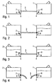
- FIG. 1 shows a tank system according to the invention with a main tank 1 and a sub tank 2, wherein the main tank 1 and the sub tank 2 each have a filler neck and can be filled independently.
- the main tank 1 and the sub tank 2 may be disposed in a truck on opposite sides of the vehicle frame.
- the main tank 1 is connected via a compensation line 3 with the sub tank 2, to allow a level balance between the main tank 1 and the sub tank 2.
- the equalizing line 3 respectively opens into the main tank 1 and into the secondary tank 2, respectively, in order to enable level compensation by the equalizing line 3 even in the case of low filling levels in the main tank 1 and in the secondary tank 2.
- the tank system shown has a valve arrangement with two outlet valves 4, 5, wherein the outlet valve 4 in the main tank 1 controls the outflow of the diesel fuel from the main tank 1 into the equalization line 3.
- the exhaust valve 5 in the sub tank 2 controls the outflow of the diesel fuel from the sub tank 2 into the equalizing pipe.
- the two exhaust valves 4, 5 each have a valve seat, which opens into the equalizing line 3 and a funnel-shaped valve cage 6 and 7, in which a valve ball 8 and 9 is movably caught.
- valve balls 8, 9 have a lower mass density than the diesel fuel, so that the valve balls 8, 9 float in the diesel fuel.
- valve cages 6, 7 are permeable to the diesel fuel and impermeable to the valve balls 8, 9.
- FIG. 2 shows, however, the state of the tank system at a first filling of the main tank 1 with an empty secondary tank. 2
- valve ball 8 of the exhaust valve 4 of the main tank 1 acts on the valve ball 8 of the exhaust valve 4 of the main tank 1, a buoyancy force due to the diesel fuel, whereby the valve ball 8 floats.
- FIG. 3 shows the state of the tank system according to the invention, when both the main tank 1 and the sub tank 2 are filled.
- FIG. 4 shows the state of the tank system according to the invention in case of leakage of the equalization line 3, which is illustrated by a tearing of the compensation line 3.
- both of the main tank 1 and the sub tank 2 a strong outflow on the exhaust valves 4, 5, whereby the valve balls 8, 9 are pressed into the associated valve seat, which then close the exhaust valves 4, 5. This prevents that in case of leakage of the compensation line 3, a large leakage occurs.
- FIGS. 5 and 6 show in a self-explanatory manner a state diagram or a state table to illustrate the operation of the tank system from the Figures 1-4 , Reference is made to avoid repetition of the above description.
Landscapes
- Engineering & Computer Science (AREA)
- Life Sciences & Earth Sciences (AREA)
- Sustainable Development (AREA)
- Sustainable Energy (AREA)
- Chemical & Material Sciences (AREA)
- Combustion & Propulsion (AREA)
- Transportation (AREA)
- Mechanical Engineering (AREA)
- Loading And Unloading Of Fuel Tanks Or Ships (AREA)
- Cooling, Air Intake And Gas Exhaust, And Fuel Tank Arrangements In Propulsion Units (AREA)
Description
Die Erfindung betrifft eine Tankanlage, insbesondere für ein Fahrzeug, wie beispielsweise ein Kraftfahrzeug (z.B. Lastkraftwagen oder Omnibus).The invention relates to a tank installation, in particular for a vehicle, such as a motor vehicle (for example a truck or omnibus).
Aus dem Stand der Technik sind Tankanlagen für Lastkraftwagen bekannt, die einen Haupttank und einen Nebentank zur Aufnahme des Kraftstoffs (z.B. Dieselkraftstoff) aufweisen, wobei der Haupttank und der Nebentank beispielsweise auf gegenüberliegenden Seiten des Fahrzeugrahmens nebeneinander angeordnet sein können. Hierbei ist es bekannt, den Haupttank über eine unten liegende Ausgleichsleitung mit dem Nebentank zu verbinden, um einen Füllstandsausgleich zwischen dem Haupttank und dem Nebentank zu ermöglichen.Tankers for trucks are known from the prior art, which have a main tank and a secondary tank for receiving the fuel (for example diesel fuel), wherein the main tank and the sub tank can be arranged side by side, for example, on opposite sides of the vehicle frame. In this case, it is known to connect the main tank to the secondary tank via an equalizing line located at the bottom, in order to enable level compensation between the main tank and the secondary tank.
Ein Nachteil dieser bekannten Tankanlage besteht darin, dass eine Undichtigkeit der Ausgleichsleitung zwischen dem Haupttank und dem Nebentank zu einem Austritt des Kraftstoffs aus der Tankanlage führt.A disadvantage of this known tank system is that a leakage of the equalization line between the main tank and the sub tank leads to an exit of the fuel from the tank system.
Ein weiterer Nachteil dieser bekannten Tankanlage besteht darin, dass keine separate Befüllung des Haupttanks ohne eine gleichzeitige Befüllung des Nebentanks möglich ist, da der Füllstand in dem Haupttank und in dem Nebentank immer ausgeglichen wird.Another disadvantage of this known tank system is that no separate filling of the main tank without simultaneous filling of the sub-tank is possible, since the level in the main tank and in the sub-tank is always balanced.
Aus
Ferner ist zum Stand der Technik hinzuweisen auf
Der Erfindung liegt deshalb die Aufgabe zugrunde, eine entsprechend verbesserte Tankanlage zu schaffen.The invention is therefore based on the object to provide a correspondingly improved tank system.
Diese Aufgabe wird durch eine erfindungsgemäße Tankanlage gemäß dem Hauptanspruch gelöst.This object is achieved by a tank system according to the invention according to the main claim.
Die erfindungsgemäße Tankanlage weist in Übereinstimmung mit dem Stand der Technik sowohl einen Haupttank als auch einen Nebentank auf, wobei die Tankanlage zusätzlich zu dem Haupttank und dem Nebentank auch weitere Tanks aufweisen kann.The tank system according to the invention has, in accordance with the prior art, both a main tank and a sub tank, wherein the tank system may also have other tanks in addition to the main tank and the sub tank.
Der Haupttank und der Nebentank dienen bei der erfindungsgemäßen Tankanlage zur Aufnahme einer Betriebsflüssigkeit des Fahrzeugs, wobei es sich vorzugsweise um Kraftstoff (z.B. Dieselkraftstoff) handelt. Die Erfindung ist jedoch hinsichtlich der Betriebsflüssigkeit nicht auf Kraftstoff beschränkt, sondern auch für andere Betriebsflüssigkeiten des Fahrzeugs geeignet.The main tank and the secondary tank are used in the tank system according to the invention for receiving a working fluid of the vehicle, which is preferably fuel (eg diesel fuel). However, the invention is in terms of operating fluid not limited to fuel, but also suitable for other operating fluids of the vehicle.
Ferner ist die Erfindung nicht beschränkt auf Tankanlagen von Fahrzeugen, sondern auch bei stationären Tankanlagen oder sonstigen Behältern realisierbar.Furthermore, the invention is not limited to tank systems of vehicles, but also in stationary fuel tanks or other containers feasible.
Darüber hinaus umfasst die erfindungsgemäße Tankanlage in Übereinstimmung mit dem Stand der Technik eine Ausgleichsleitung zwischen dem Haupttank und dem Nebentank, wobei die Ausgleichsleitung einen Füllstandsausgleich zwischen dem Haupttank und dem Nebentank ermöglicht, indem die Betriebsflüssigkeit von dem Haupttank in den Nebentank oder in umgekehrter Richtung durch die Ausgleichsleitung fließt.In addition, in accordance with the prior art tank system according to the invention comprises an equalization line between the main tank and the subtank, the equalization line enabling level compensation between the main tank and the subtank by passing the working fluid from the main tank to the subtank or vice versa Equalization line flows.
Die erfindungsgemäße Tankanlage zeichnet sich durch eine Ventilanordnung aus, die den Ausfluss aus dem Haupttank und/oder aus dem Nebentank in die Ausgleichsleitung steuert.The tank system according to the invention is characterized by a valve arrangement which controls the outflow from the main tank and / or from the sub tank into the equalization line.
In einem bevorzugten Ausführungsbeispiel der Erfindung schließt die Ventilanordnung den Ausfluss aus dem Haupttank und aus dem Nebentank bei einer Undichtigkeit der Ausgleichsleitung und verhindert dadurch ein Austreten der Betriebsflüssigkeit aus der undichten Ausgleichsleitung, wodurch eine Leckage verhindert wird.In a preferred embodiment of the invention, the valve arrangement closes the outflow from the main tank and from the sub tank in the event of a leakage of the compensation line and thereby prevents the operating fluid from escaping from the leaking compensation line, thereby preventing leakage.
Darüber hinaus schließt die Ventilanordnung bei dem bevorzugten Ausführungsbeispiel der Erfindung auch bei einer Erstbefüllung des Haupttanks bei leerem Nebentank, wodurch eine separate Befüllung des Haupttanks ohne einen Füllstandsausgleich mit dem leeren Nebentank ermöglicht wird.In addition, in the preferred embodiment of the invention, the valve arrangement also closes when the main tank is first filled with the auxiliary tank empty, thereby allowing separate filling of the main tank without leveling with the empty sub tank.
Erfindungsgemäß umfasst die Ventilanordnung an dem Haupttank und an dem Nebentank jeweils ein Auslassventil, das den Ausfluss aus dem Haupttank bzw. aus dem Nebentank in die Ausgleichsleitung steuert.According to the invention, the valve arrangement on the main tank and on the secondary tank respectively comprises an outlet valve which controls the outflow from the main tank or from the secondary tank into the equalization line.
Das Auslassventil des Haupttanks schließt vorzugsweise nur dann, wenn der Haupttank zumindest teilweise gefüllt ist und wenn gleichzeitig der Nebentank leer ist oder die Ausgleichsleitung undicht ist. Ansonsten öffnet das Auslassventil des Haupttanks dagegen.The outlet valve of the main tank preferably closes only when the main tank is at least partially filled and at the same time the sub tank is empty or the equalizing line is leaking. Otherwise, the exhaust valve of the main tank opens against it.
Darüber hinaus schließt das Auslassventil des Nebentanks vorzugsweise nur dann, wenn der Nebentank zumindest teilweise gefüllt ist und wenn gleichzeitig der Haupttank leer ist oder die Ausgleichsleitung undicht ist. Ansonsten öffnet das Auslassventil des Nebentanks dagegen.Moreover, the outlet valve of the sub-tank preferably closes only when the sub-tank is at least partially filled and at the same time that the main tank is empty or the equalization line is leaking. Otherwise, the outlet valve of the sub tank opens against it.
In dem bevorzugten Ausführungsbeispiel der Erfindung weisen die Auslassventile des Haupttanks und des Nebentanks eine besondere Bauweise auf, die sich als vorteilhaft erwiesen hat. So weisen die Auslassventile vorzugsweise einen Ventilsitz auf, der in die Ausgleichsleitung mündet, sowie einen Ventilkäfig, der an dem Ventilsitz angeordnet ist und in den Tankinnenraum hinein ragt. In dem Ventilkäfig ist ein Ventilelement (z.B. Ventilkugel) frei beweglich gefangen, wobei das Ventilelement den Ventilsitz bei einer Anlage an dem Ventilsitz abdichtet, so dass das Auslassventil schließt.In the preferred embodiment of the invention, the outlet valves of the main tank and the sub-tank have a special construction, which has proven to be advantageous. Thus, the outlet valves preferably have a valve seat, which opens into the compensation line, and a valve cage, which is arranged on the valve seat and projects into the interior of the tank. In the valve cage, a valve element (e.g., valve ball) is trapped in a freely movable manner, the valve element sealing the valve seat against the valve seat so that the exhaust valve closes.
Zum einen wirkt auf das Ventilelement eine Auftriebskraft, da das Ventilelement in der Betriebsflüssigkeit (z.B. Dieselkraftstoff) in dem Tankinnenraum aufschwimmt.On the one hand, a buoyancy force acts on the valve member, as the valve member floats in the working fluid (e.g., diesel fuel) in the tank interior.
Zum anderen wirkt auf das Ventilelement aber auch eine Strömungskraft aufgrund des Ausflusses aus dem Haupt- bzw. Nebentank in die Ausgleichsleitung.On the other hand acts on the valve element but also a flow force due to the outflow from the main or secondary tank in the compensation line.
Die Abmessungen des Ventilelements und die Massendichte des Ventilelements sind relativ zu der Massendichte der Betriebsflüssigkeit vorzugsweise so abgestimmt, dass das Ventilelement nur bei einem starken Ausfluss (d.h. bei einem stärkeren Ausfluss als bei einem kontinuierlichen Füllstandsausgleich) durch die Ausgleichsleitung in den Ventilsitz gedrückt wird und den Ventilsitz ansonsten freigibt und zwar bei leerem Tank aufgrund der auf das Ventilelement wirkenden Schwerkraft und bei vollem Tank aufgrund der auf das Ventilelement wirkenden Auftriebskraft. Hierbei ist zu unterscheiden zwischen einem schwachen Ausfluss durch die Ausgleichsleitung, wie er bei einem kontinuierlichen Füllstandsausgleich auftritt, und einem starken Ausfluss aus der Ausgleichsleitung, wie er bei einer Undichtigkeit der Ausgleichsleitung oder bei der Erstbefüllung des Haupttanks bei leerem Nebentank auftritt. Das Auslassventil schließt also vorzugsweise nur bei einem starken Ausfluss, nicht dagegen bei einem schwachen Ausfluss im Rahmen eines kontinuierlichen FüllstandsausgleichsThe dimensions of the valve element and the mass density of the valve element are preferably adjusted relative to the mass density of the operating fluid so that the valve element is pressed into the valve seat through the compensation line only in the case of a strong outflow (ie with a greater outflow than with a continuous level compensation) Valve seat otherwise releases, namely with an empty tank due to the force acting on the valve element gravity and full tank due to the force acting on the valve element buoyancy. A distinction must be made here between a weak outflow through the equalization line, as occurs in a continuous level compensation, and a strong outflow from the compensation line, as occurs in a leakage of the compensation line or when first filling the main tank with an empty sub tank. The outlet valve therefore preferably closes only with a strong outflow, but not with a weak outflow in the context of a continuous level compensation
Ferner ist zu erwähnen, dass die Ausgleichsleitung vorzugsweise unten in den Haupttank und in den Nebentank mündet, wie es an sich aus dem Stand der Technik bekannt ist. Beispielsweise kann die Ausgleichsleitung im unteren Viertel, Fünftel oder sogar im unteren Achtel des Haupttanks bzw. des Nebentanks in den Haupttank bzw. in den Nebentank münden, um auch bei einem niedrigen Füllstand einen Füllstandsausgleich über die Ausgleichsleitung zu ermöglichen.It should also be mentioned that the equalization line preferably opens down into the main tank and into the auxiliary tank, as is known per se from the prior art. For example, the equalizing pipe in the lower quarter, fifth or even lower eighth of the main tank or the secondary tank may open into the main tank or the secondary tank, to allow a level compensation via the compensation line even at a low level.
Darüber hinaus ist zu erwähnen, dass die Ventilanordnung bzw. die Auslassventile vorzugsweise eigenmediumbetätigt sind. Dies bedeutet, dass die Ventilstellung durch die Betriebsflüssigkeit gesteuert wird und zwar konkret durch den Füllstand der Betriebsflüssigkeit und die Strömung der Betriebsflüssigkeit durch die Ausgleichsleitung. Davon zu unterscheiden ist eine externe Ansteuerung der Ventilanordnung bzw. des Auslassventils durch ein externes Steuersignal, wie es beispielsweise bei pneumatischen oder elektrischen Ventilen der Fall ist.In addition, it should be mentioned that the valve arrangement or the outlet valves are preferably self-medium-actuated. This means that the valve position is controlled by the operating fluid and specifically by the level of the operating fluid and the flow of the operating fluid through the compensation line. To distinguish this is an external control of the valve assembly and the exhaust valve by an external control signal, as is the case for example with pneumatic or electric valves.
Schließlich umfasst die Erfindung auch ein komplettes Fahrzeug mit der vorstehend beschriebenen Tankanlage, wobei es sich vorzugsweise um ein Kraftfahrzeug (z.B. Lastkraftwagen oder Omnibus) handeln kann.Finally, the invention also encompasses a complete vehicle with the tank system described above, which may preferably be a motor vehicle (for example a truck or omnibus).
Andere vorteilhafte Weiterbildungen der Erfindung sind in den Unteransprüchen gekennzeichnet oder werden nachstehend zusammen mit der Beschreibung des bevorzugten Ausführungsbeispiels der Erfindung anhand der Figuren näher erläutert. Es zeigen:
- Figur 1
- eine schematische Darstellung einer erfindungsgemäßen Tankanlage bei leerem Haupttank und leerem Nebentank,
Figur 2- die Tankanlage aus
Figur 1 bei vollem Haupttank und leerem Haupttank, Figur 3- die Tankanlage aus den
Figuren 1 und 2 bei vollem Haupttank und vollem Nebentank, Figur 4- die Tankanlage aus den
Figuren 1 bis 3 bei einer Undichtigkeit der Ausgleichsleitung zwischen dem Haupttank und dem Nebentank, Figur 5- ein Zustandsdiagramm zur Verdeutlichung der Betriebsweise der Tankanlage aus den
Figuren 1 bis 4 , sowie Figur 6- eine Zustandstabelle der Tankanlage aus den
Figuren 1 bis 4 .
- FIG. 1
- a schematic representation of a tank system according to the invention with empty main tank and empty sub tank,
- FIG. 2
- the tank system off
FIG. 1 with full main tank and empty main tank, - FIG. 3
- the tank system from the
Figures 1 and 2 with full main tank and full subsidiary tank, - FIG. 4
- the tank system from the
FIGS. 1 to 3 in the event of a leakage between the main tank and the sub tank, - FIG. 5
- a state diagram to illustrate the operation of the tank system from the
FIGS. 1 to 4 , such as - FIG. 6
- a state table of the tank system from the
FIGS. 1 to 4 ,
Der Haupttank 1 ist über eine Ausgleichsleitung 3 mit dem Nebentank 2 verbunden, um einen Füllstandsausgleich zwischen dem Haupttank 1 und dem Nebentank 2 zu ermöglichen. Die Ausgleichsleitung 3 mündet hierbei jeweils unten in den Haupttank 1 bzw. in den Nebentank 2, um auch bei geringen Füllständen in dem Haupttank 1 und in dem Nebentank 2 einen Füllstandsausgleich durch die Ausgleichsleitung 3 zu ermöglichen.The main tank 1 is connected via a
Die dargestellte Tankanlage weist eine Ventilanordnung mit zwei Auslassventilen 4, 5 auf, wobei das Auslassventil 4 in dem Haupttank 1 den Ausfluss des Dieselkraftstoffs aus dem Haupttank 1 in die Ausgleichsleitung 3 steuert. Das Auslassventil 5 in dem Nebentank 2 steuert dagegen den Ausfluss des Dieselkraftstoffs aus dem Nebentank 2 in die Ausgleichsleitung.The tank system shown has a valve arrangement with two
Die beiden Auslassventile 4, 5 weisen jeweils einen Ventilsitz auf, der in die Ausgleichsleitung 3 mündet sowie einen trichterförmigen Ventilkäfig 6 bzw. 7, in dem eine Ventilkugel 8 bzw. 9 beweglich gefangen ist.The two
Die Ventilkugeln 8, 9 weisen eine geringere Massendichte auf als der Dieselkraftstoff, so dass die Ventilkugeln 8, 9 in dem Dieselkraftstoff aufschwimmen.The
Weiterhin ist zu erwähnen, dass die Ventilkäfige 6, 7 für den Dieselkraftstoff durchlässig und für die Ventilkugeln 8, 9 undurchlässig sind.It should also be mentioned that the
In dem in
Zum einen wirkt dabei auf die Ventilkugel 8 des Auslassventils 4 des Haupttanks 1 eine Auftriebskraft aufgrund des Dieselkraftstoffs, wodurch die Ventilkugel 8 aufschwimmt.On the one hand acts on the
Zum anderen entsteht bei steigendem Füllstand in dem Haupttank 1 ein Ausfluss aus dem Haupttank 1 durch die Ausgleichsleitung 3 in den Nebentank, wobei dieser Ausfluss die Ventilkugel 8 in den zugehörigen Ventilsitz drückt und dadurch das Auslassventil 4 des Haupttanks 1 schließt. Dadurch wird verhindert, dass bei einer Erstbefüllung des Haupttanks 1 bei leerem Nebentank 2 weiterer Kraftstoff über die Ausgleichsleitung 3 in den Nebentank 2 abfließt.On the other hand arises with increasing level in the main tank 1, an outflow from the main tank 1 through the
Hierbei wirkt auf die Ventilkugeln 8, 9 die Auftriebskraft aufgrund des Dieselkraftstoffs, so dass die Ventilkugeln 8, 9 in den zugehörigen Ventilkäfigen 6, 7 aufschwimmen. Dies hat zur Folge, dass die beiden Auslassventile 4, 5 öffnen, was einen Füllstandsausgleich zwischen dem Haupttank 1 einerseits und dem Nebentank 2 andererseits über die Ausgleichsleitung 3 ermöglicht. Bei diesem Füllstandsausgleich tritt zwar ebenfalls ein kleiner Flüssigkeitsstrom durch die Ausgleichsleitung 3 auf, jedoch ist dieser Flüssigkeitsstrom nicht stark genug, um die Ventilkugeln 8, 9 in den zugehörigen Ventilsitz zu drücken.In this case, the buoyancy force due to the diesel fuel acts on the
Die
- 11
- Haupttankmain tank
- 22
- NebentankIn addition to tank
- 33
- Ausgleichsleitungcompensation line
- 44
- Auslassventil des HaupttanksExhaust valve of the main tank
- 55
- Auslassventil des NebentanksOutlet valve of the secondary tank
- 66
- Ventilkäfigvalve cage
- 77
- Ventilkäfigvalve cage
- 88th
- Ventilkugelvalve ball
- 99
- Ventilkugelvalve ball
Claims (8)
- A tank system, in particular for a vehicle, in particular for a motor vehicle, in particular for a lorry or an omnibus, havinga) a main tank (1) for receiving an operating liquid, in particular for receiving fuel,b) an auxiliary tank (2) for receiving the operating liquid, andc) an equalizing line (3) between the main tank (1) and the auxiliary tank (2) for equalizing the filling level between the main tank (1) and the auxiliary tank (2) by means of a filling level-dependent outflow from the main tank (1) and from the auxiliary tank (2),d) a valve arrangement (4, 5) which controls the outflow from the main tank (1) and/or from the auxiliary tank (2) into the equalizing line (3), characterizede) in that the valve arrangement (4, 5) closes in the event of a leak of the equalizing line (3) and prevents an escape of the operating liquid from the equalizing line (3) as a result, andf) in that the valve arrangement (4, 5) has in each case one outlet valve (4, 5) at the main tank (1) and at the auxiliary tank (2), which outlet valve (4, 5) controls the outflow from the main tank (1) and from the auxiliary tank (2), respectively, into the equalizing line (3).
- The tank system according to Claim 1, characterized in that the valve arrangement (4, 5) closes in the event of initial filling of the main tank (1) and prevents the filling level equalization between the full main tank (1) and the empty auxiliary tank (2) during the initial filling of the main tank (1) as a result.
- The tank system according to either of the preceding claims, characterized in that the outlet valves (4, 5) of the main tank (1) and/or of the auxiliary tank (2) have the hollowing:a) a valve seat which opens into the equalizing line (3),b) a valve cage (6, 7) which is arranged on the valve seat and protrudes into the tank interior space,c) a valve element (8, 9) which is captured in a freely movable manner in the valve cage (6, 7) and seals the valve seat in the case of contact against the valve seat.
- The tank system according to Claim 3, characterizeda) in that the valve cage (6, 7) is widened in a funnel-shaped manner inwardly into the tank interior space, and/orb) in that the valve cage (6, 7) is permeable for the operating liquid and is impermeable for the valve element, and/orc) in that the valve element (8, 9) is a valve ball.
- The tank system according to Claim 3 or 4, characterizeda) in that the valve element (8, 9) has a smaller mass density than the operating liquid, with the result that the valve element (8, 9) floats in the operating liquid, and/orb) in that the valve element (8, 9) is pressed into the valve seat by way of a pronounced out flow and closes the outlet valve (4, 5), and otherwise floats in the operating liquid and opens the cutlet valve (4, 5), and/orc) in that the mass density of the valve element (8, 9) is adapted to the mass density of the operating liquid in such a way that the outlet valve (4, 5) closes only in the event of a more pronounced outflow than in the event of a continuous filling level equalization, and otherwise opens automatically.
- The tank system according to one of the preceding claims, characterized in that the equalizing line (3) opens in each case at the bottom into the main tank (1) and into the auxiliary tank (2), in particular in the lower quarter, fifth or eighth of the main tank (1) and the auxiliary tank (2), in order to make a filling level equalization between the main tank (1) and the auxiliary tank (2) possible even in the case of a low filling level.
- The tank system according to one of the preceding claims, characterized in that the valve arrangement (4, 5) is actuated by way of its intrinsic medium and automatically controls the outflow from the main tank (1) and from the auxiliary tank (2) without an external actuation.
- A vehicle, in particular motor vehicle, in particular lorry or omnibus, having a tank system according to one of the preceding claims.
Applications Claiming Priority (1)
| Application Number | Priority Date | Filing Date | Title |
|---|---|---|---|
| DE102013021007.0A DE102013021007A1 (en) | 2013-12-13 | 2013-12-13 | Tank system for a vehicle |
Publications (2)
| Publication Number | Publication Date |
|---|---|
| EP2883733A1 EP2883733A1 (en) | 2015-06-17 |
| EP2883733B1 true EP2883733B1 (en) | 2016-02-24 |
Family
ID=51263183
Family Applications (1)
| Application Number | Title | Priority Date | Filing Date |
|---|---|---|---|
| EP14002669.1A Active EP2883733B1 (en) | 2013-12-13 | 2014-07-31 | Tank system for a vehicle |
Country Status (2)
| Country | Link |
|---|---|
| EP (1) | EP2883733B1 (en) |
| DE (1) | DE102013021007A1 (en) |
Families Citing this family (2)
| Publication number | Priority date | Publication date | Assignee | Title |
|---|---|---|---|---|
| CN114658576A (en) * | 2022-03-31 | 2022-06-24 | 东风华神汽车有限公司 | Commercial vehicle owner and auxiliary fuel tank control method, device, equipment and readable storage medium |
| CN114776493B (en) * | 2022-04-19 | 2024-03-19 | 潍柴动力股份有限公司 | Vehicle low-temperature heating method, device, system, equipment and storage medium |
Family Cites Families (6)
| Publication number | Priority date | Publication date | Assignee | Title |
|---|---|---|---|---|
| GB1459203A (en) * | 1973-12-07 | 1976-12-22 | Sundaravej K | Fuel storage tanks |
| US5636654A (en) * | 1995-02-22 | 1997-06-10 | Helm; C. Bradford | Fuel equalization line for vehicles and method of using same |
| JP3735489B2 (en) * | 1999-06-29 | 2006-01-18 | 株式会社クボタ | Fuel supply device for engine for work equipment |
| US6789568B1 (en) * | 2003-06-17 | 2004-09-14 | Case, Llc | Fluid flow control mechansim |
| GB0725176D0 (en) * | 2007-12-22 | 2008-01-30 | Agco Sa | Implement attachment |
| US8899627B2 (en) * | 2011-01-13 | 2014-12-02 | Wacker Neuson Production Americas Llc | Multiple fuel tank system |
-
2013
- 2013-12-13 DE DE102013021007.0A patent/DE102013021007A1/en not_active Withdrawn
-
2014
- 2014-07-31 EP EP14002669.1A patent/EP2883733B1/en active Active
Also Published As
| Publication number | Publication date |
|---|---|
| DE102013021007A1 (en) | 2015-06-18 |
| EP2883733A1 (en) | 2015-06-17 |
Similar Documents
| Publication | Publication Date | Title |
|---|---|---|
| DE3121621C2 (en) | "Ventilation device for fuel tanks of vehicles, in particular of motor vehicles" | |
| EP2883733B1 (en) | Tank system for a vehicle | |
| DE102008014820A1 (en) | Fuel tank for motor vehicles | |
| DE102005043745A1 (en) | Ventilation system for fuel tank of motor vehicle, has connection channel, float valve and opening for conducting liquid fuel from siphon shaped filling vent line to fuel tank, and fuel filling pipe arranged within lower region of siphon | |
| EP2842785B1 (en) | Commercial vehicle tank | |
| EP3452325B1 (en) | Tank system of a motor vehicle comprising a volume-modifying element | |
| DE102013013212A1 (en) | Universal shut-off valve | |
| DE102010001216A1 (en) | Container, in particular for hydraulic vehicle brake systems | |
| DE102016223957A1 (en) | Bleed valve for a working fluid container of a motor vehicle | |
| DE10110189B4 (en) | Fuel tank | |
| DE102006055285B4 (en) | Oil filter with bypass valve and oil reservoir | |
| DE102016105025A1 (en) | breather | |
| EP2008857B1 (en) | Fuel tank for motor vehicles | |
| WO1999028143A1 (en) | Device for preventing a fuel tank to be overfilled | |
| EP2761982A1 (en) | Safety valve for a plastic tank, in particular a plastic liquid manure tank | |
| DE202008003685U1 (en) | Ventilation valve for tank vehicles | |
| EP2842784A1 (en) | Commercial vehicle tank | |
| DE19956931A1 (en) | Valve for fuel tank in motor vehicles has pressure valve mounted on valve housing and opening at predetermined excess pressure in tank and with filling ventilation opening closable | |
| EP1154909A1 (en) | Valve and fuel tank provided with a valve for a motor vehicle | |
| DE10027569B4 (en) | Fuel tank of a motor vehicle with pressure relief valves | |
| EP0906844B1 (en) | Fuel tank for a motor vehicle | |
| AT405643B (en) | DEVICE FOR PREVENTING OVERFILLING OF A FUEL TANK | |
| WO2021151613A1 (en) | Hydraulically actuable valve for a high-pressure tank | |
| DE102011050416A1 (en) | filler cap | |
| DE102015210206A1 (en) | Liquid tank with float-controlled filling device |
Legal Events
| Date | Code | Title | Description |
|---|---|---|---|
| PUAI | Public reference made under article 153(3) epc to a published international application that has entered the european phase |
Free format text: ORIGINAL CODE: 0009012 |
|
| 17P | Request for examination filed |
Effective date: 20150317 |
|
| AK | Designated contracting states |
Kind code of ref document: A1 Designated state(s): AL AT BE BG CH CY CZ DE DK EE ES FI FR GB GR HR HU IE IS IT LI LT LU LV MC MK MT NL NO PL PT RO RS SE SI SK SM TR |
|
| AX | Request for extension of the european patent |
Extension state: BA ME |
|
| GRAP | Despatch of communication of intention to grant a patent |
Free format text: ORIGINAL CODE: EPIDOSNIGR1 |
|
| INTG | Intention to grant announced |
Effective date: 20151014 |
|
| GRAS | Grant fee paid |
Free format text: ORIGINAL CODE: EPIDOSNIGR3 |
|
| INTG | Intention to grant announced |
Effective date: 20151119 |
|
| GRAA | (expected) grant |
Free format text: ORIGINAL CODE: 0009210 |
|
| AK | Designated contracting states |
Kind code of ref document: B1 Designated state(s): AL AT BE BG CH CY CZ DE DK EE ES FI FR GB GR HR HU IE IS IT LI LT LU LV MC MK MT NL NO PL PT RO RS SE SI SK SM TR |
|
| REG | Reference to a national code |
Ref country code: GB Ref legal event code: FG4D Free format text: NOT ENGLISH |
|
| REG | Reference to a national code |
Ref country code: CH Ref legal event code: EP |
|
| REG | Reference to a national code |
Ref country code: AT Ref legal event code: REF Ref document number: 776495 Country of ref document: AT Kind code of ref document: T Effective date: 20160315 |
|
| REG | Reference to a national code |
Ref country code: IE Ref legal event code: FG4D Free format text: LANGUAGE OF EP DOCUMENT: GERMAN |
|
| REG | Reference to a national code |
Ref country code: DE Ref legal event code: R096 Ref document number: 502014000375 Country of ref document: DE |
|
| REG | Reference to a national code |
Ref country code: NL Ref legal event code: FP |
|
| REG | Reference to a national code |
Ref country code: SE Ref legal event code: TRGR |
|
| REG | Reference to a national code |
Ref country code: LT Ref legal event code: MG4D |
|
| REG | Reference to a national code |
Ref country code: FR Ref legal event code: PLFP Year of fee payment: 3 |
|
| PG25 | Lapsed in a contracting state [announced via postgrant information from national office to epo] |
Ref country code: ES Free format text: LAPSE BECAUSE OF FAILURE TO SUBMIT A TRANSLATION OF THE DESCRIPTION OR TO PAY THE FEE WITHIN THE PRESCRIBED TIME-LIMIT Effective date: 20160224 Ref country code: NO Free format text: LAPSE BECAUSE OF FAILURE TO SUBMIT A TRANSLATION OF THE DESCRIPTION OR TO PAY THE FEE WITHIN THE PRESCRIBED TIME-LIMIT Effective date: 20160524 Ref country code: FI Free format text: LAPSE BECAUSE OF FAILURE TO SUBMIT A TRANSLATION OF THE DESCRIPTION OR TO PAY THE FEE WITHIN THE PRESCRIBED TIME-LIMIT Effective date: 20160224 Ref country code: GR Free format text: LAPSE BECAUSE OF FAILURE TO SUBMIT A TRANSLATION OF THE DESCRIPTION OR TO PAY THE FEE WITHIN THE PRESCRIBED TIME-LIMIT Effective date: 20160525 Ref country code: HR Free format text: LAPSE BECAUSE OF FAILURE TO SUBMIT A TRANSLATION OF THE DESCRIPTION OR TO PAY THE FEE WITHIN THE PRESCRIBED TIME-LIMIT Effective date: 20160224 |
|
| PG25 | Lapsed in a contracting state [announced via postgrant information from national office to epo] |
Ref country code: RS Free format text: LAPSE BECAUSE OF FAILURE TO SUBMIT A TRANSLATION OF THE DESCRIPTION OR TO PAY THE FEE WITHIN THE PRESCRIBED TIME-LIMIT Effective date: 20160224 Ref country code: PL Free format text: LAPSE BECAUSE OF FAILURE TO SUBMIT A TRANSLATION OF THE DESCRIPTION OR TO PAY THE FEE WITHIN THE PRESCRIBED TIME-LIMIT Effective date: 20160224 Ref country code: LV Free format text: LAPSE BECAUSE OF FAILURE TO SUBMIT A TRANSLATION OF THE DESCRIPTION OR TO PAY THE FEE WITHIN THE PRESCRIBED TIME-LIMIT Effective date: 20160224 Ref country code: PT Free format text: LAPSE BECAUSE OF FAILURE TO SUBMIT A TRANSLATION OF THE DESCRIPTION OR TO PAY THE FEE WITHIN THE PRESCRIBED TIME-LIMIT Effective date: 20160624 Ref country code: LT Free format text: LAPSE BECAUSE OF FAILURE TO SUBMIT A TRANSLATION OF THE DESCRIPTION OR TO PAY THE FEE WITHIN THE PRESCRIBED TIME-LIMIT Effective date: 20160224 |
|
| PG25 | Lapsed in a contracting state [announced via postgrant information from national office to epo] |
Ref country code: DK Free format text: LAPSE BECAUSE OF FAILURE TO SUBMIT A TRANSLATION OF THE DESCRIPTION OR TO PAY THE FEE WITHIN THE PRESCRIBED TIME-LIMIT Effective date: 20160224 Ref country code: EE Free format text: LAPSE BECAUSE OF FAILURE TO SUBMIT A TRANSLATION OF THE DESCRIPTION OR TO PAY THE FEE WITHIN THE PRESCRIBED TIME-LIMIT Effective date: 20160224 |
|
| REG | Reference to a national code |
Ref country code: DE Ref legal event code: R097 Ref document number: 502014000375 Country of ref document: DE |
|
| PG25 | Lapsed in a contracting state [announced via postgrant information from national office to epo] |
Ref country code: RO Free format text: LAPSE BECAUSE OF FAILURE TO SUBMIT A TRANSLATION OF THE DESCRIPTION OR TO PAY THE FEE WITHIN THE PRESCRIBED TIME-LIMIT Effective date: 20160224 Ref country code: CZ Free format text: LAPSE BECAUSE OF FAILURE TO SUBMIT A TRANSLATION OF THE DESCRIPTION OR TO PAY THE FEE WITHIN THE PRESCRIBED TIME-LIMIT Effective date: 20160224 Ref country code: SK Free format text: LAPSE BECAUSE OF FAILURE TO SUBMIT A TRANSLATION OF THE DESCRIPTION OR TO PAY THE FEE WITHIN THE PRESCRIBED TIME-LIMIT Effective date: 20160224 Ref country code: SM Free format text: LAPSE BECAUSE OF FAILURE TO SUBMIT A TRANSLATION OF THE DESCRIPTION OR TO PAY THE FEE WITHIN THE PRESCRIBED TIME-LIMIT Effective date: 20160224 |
|
| PG25 | Lapsed in a contracting state [announced via postgrant information from national office to epo] |
Ref country code: BE Free format text: LAPSE BECAUSE OF NON-PAYMENT OF DUE FEES Effective date: 20160731 |
|
| PLBE | No opposition filed within time limit |
Free format text: ORIGINAL CODE: 0009261 |
|
| STAA | Information on the status of an ep patent application or granted ep patent |
Free format text: STATUS: NO OPPOSITION FILED WITHIN TIME LIMIT |
|
| 26N | No opposition filed |
Effective date: 20161125 |
|
| PG25 | Lapsed in a contracting state [announced via postgrant information from national office to epo] |
Ref country code: SI Free format text: LAPSE BECAUSE OF FAILURE TO SUBMIT A TRANSLATION OF THE DESCRIPTION OR TO PAY THE FEE WITHIN THE PRESCRIBED TIME-LIMIT Effective date: 20160224 Ref country code: BG Free format text: LAPSE BECAUSE OF FAILURE TO SUBMIT A TRANSLATION OF THE DESCRIPTION OR TO PAY THE FEE WITHIN THE PRESCRIBED TIME-LIMIT Effective date: 20160524 |
|
| PG25 | Lapsed in a contracting state [announced via postgrant information from national office to epo] |
Ref country code: MC Free format text: LAPSE BECAUSE OF FAILURE TO SUBMIT A TRANSLATION OF THE DESCRIPTION OR TO PAY THE FEE WITHIN THE PRESCRIBED TIME-LIMIT Effective date: 20160224 |
|
| REG | Reference to a national code |
Ref country code: IE Ref legal event code: MM4A |
|
| REG | Reference to a national code |
Ref country code: FR Ref legal event code: PLFP Year of fee payment: 4 |
|
| PG25 | Lapsed in a contracting state [announced via postgrant information from national office to epo] |
Ref country code: IE Free format text: LAPSE BECAUSE OF NON-PAYMENT OF DUE FEES Effective date: 20160731 |
|
| PG25 | Lapsed in a contracting state [announced via postgrant information from national office to epo] |
Ref country code: LU Free format text: LAPSE BECAUSE OF NON-PAYMENT OF DUE FEES Effective date: 20160731 |
|
| REG | Reference to a national code |
Ref country code: CH Ref legal event code: PL |
|
| PG25 | Lapsed in a contracting state [announced via postgrant information from national office to epo] |
Ref country code: CH Free format text: LAPSE BECAUSE OF NON-PAYMENT OF DUE FEES Effective date: 20170731 Ref country code: LI Free format text: LAPSE BECAUSE OF NON-PAYMENT OF DUE FEES Effective date: 20170731 |
|
| PG25 | Lapsed in a contracting state [announced via postgrant information from national office to epo] |
Ref country code: HU Free format text: LAPSE BECAUSE OF FAILURE TO SUBMIT A TRANSLATION OF THE DESCRIPTION OR TO PAY THE FEE WITHIN THE PRESCRIBED TIME-LIMIT; INVALID AB INITIO Effective date: 20140731 |
|
| PG25 | Lapsed in a contracting state [announced via postgrant information from national office to epo] |
Ref country code: CY Free format text: LAPSE BECAUSE OF FAILURE TO SUBMIT A TRANSLATION OF THE DESCRIPTION OR TO PAY THE FEE WITHIN THE PRESCRIBED TIME-LIMIT Effective date: 20160224 Ref country code: MK Free format text: LAPSE BECAUSE OF FAILURE TO SUBMIT A TRANSLATION OF THE DESCRIPTION OR TO PAY THE FEE WITHIN THE PRESCRIBED TIME-LIMIT Effective date: 20160224 Ref country code: IS Free format text: LAPSE BECAUSE OF FAILURE TO SUBMIT A TRANSLATION OF THE DESCRIPTION OR TO PAY THE FEE WITHIN THE PRESCRIBED TIME-LIMIT Effective date: 20160224 Ref country code: MT Free format text: LAPSE BECAUSE OF FAILURE TO SUBMIT A TRANSLATION OF THE DESCRIPTION OR TO PAY THE FEE WITHIN THE PRESCRIBED TIME-LIMIT Effective date: 20160224 |
|
| REG | Reference to a national code |
Ref country code: FR Ref legal event code: PLFP Year of fee payment: 5 |
|
| PG25 | Lapsed in a contracting state [announced via postgrant information from national office to epo] |
Ref country code: TR Free format text: LAPSE BECAUSE OF FAILURE TO SUBMIT A TRANSLATION OF THE DESCRIPTION OR TO PAY THE FEE WITHIN THE PRESCRIBED TIME-LIMIT Effective date: 20160224 Ref country code: AL Free format text: LAPSE BECAUSE OF FAILURE TO SUBMIT A TRANSLATION OF THE DESCRIPTION OR TO PAY THE FEE WITHIN THE PRESCRIBED TIME-LIMIT Effective date: 20160224 |
|
| GBPC | Gb: european patent ceased through non-payment of renewal fee |
Effective date: 20180731 |
|
| PG25 | Lapsed in a contracting state [announced via postgrant information from national office to epo] |
Ref country code: GB Free format text: LAPSE BECAUSE OF NON-PAYMENT OF DUE FEES Effective date: 20180731 |
|
| REG | Reference to a national code |
Ref country code: DE Ref legal event code: R081 Ref document number: 502014000375 Country of ref document: DE Owner name: MAN TRUCK & BUS SE, DE Free format text: FORMER OWNER: MAN TRUCK & BUS AG, 80995 MUENCHEN, DE |
|
| REG | Reference to a national code |
Ref country code: AT Ref legal event code: MM01 Ref document number: 776495 Country of ref document: AT Kind code of ref document: T Effective date: 20190731 |
|
| PG25 | Lapsed in a contracting state [announced via postgrant information from national office to epo] |
Ref country code: AT Free format text: LAPSE BECAUSE OF NON-PAYMENT OF DUE FEES Effective date: 20190731 |
|
| PGFP | Annual fee paid to national office [announced via postgrant information from national office to epo] |
Ref country code: SE Payment date: 20230317 Year of fee payment: 10 |
|
| PGFP | Annual fee paid to national office [announced via postgrant information from national office to epo] |
Ref country code: IT Payment date: 20230721 Year of fee payment: 10 |
|
| PGFP | Annual fee paid to national office [announced via postgrant information from national office to epo] |
Ref country code: FR Payment date: 20230725 Year of fee payment: 10 Ref country code: DE Payment date: 20230726 Year of fee payment: 10 |
|
| PGFP | Annual fee paid to national office [announced via postgrant information from national office to epo] |
Ref country code: NL Payment date: 20240725 Year of fee payment: 11 |