EP0906844B1 - Fuel tank for a motor vehicle - Google Patents
Fuel tank for a motor vehicle Download PDFInfo
- Publication number
- EP0906844B1 EP0906844B1 EP98117438A EP98117438A EP0906844B1 EP 0906844 B1 EP0906844 B1 EP 0906844B1 EP 98117438 A EP98117438 A EP 98117438A EP 98117438 A EP98117438 A EP 98117438A EP 0906844 B1 EP0906844 B1 EP 0906844B1
- Authority
- EP
- European Patent Office
- Prior art keywords
- fuel tank
- filler tube
- valve
- fuel
- opening
- Prior art date
- Legal status (The legal status is an assumption and is not a legal conclusion. Google has not performed a legal analysis and makes no representation as to the accuracy of the status listed.)
- Expired - Lifetime
Links
- 239000002828 fuel tank Substances 0.000 title claims description 27
- 239000000945 filler Substances 0.000 claims description 23
- 239000000446 fuel Substances 0.000 claims description 16
- 239000012530 fluid Substances 0.000 claims description 3
- 230000003068 static effect Effects 0.000 claims description 3
- 239000007788 liquid Substances 0.000 description 4
- 238000000034 method Methods 0.000 description 3
- OKTJSMMVPCPJKN-UHFFFAOYSA-N Carbon Chemical compound [C] OKTJSMMVPCPJKN-UHFFFAOYSA-N 0.000 description 2
- 238000009434 installation Methods 0.000 description 2
- 230000015572 biosynthetic process Effects 0.000 description 1
- 238000010586 diagram Methods 0.000 description 1
Images
Classifications
-
- B—PERFORMING OPERATIONS; TRANSPORTING
- B60—VEHICLES IN GENERAL
- B60K—ARRANGEMENT OR MOUNTING OF PROPULSION UNITS OR OF TRANSMISSIONS IN VEHICLES; ARRANGEMENT OR MOUNTING OF PLURAL DIVERSE PRIME-MOVERS IN VEHICLES; AUXILIARY DRIVES FOR VEHICLES; INSTRUMENTATION OR DASHBOARDS FOR VEHICLES; ARRANGEMENTS IN CONNECTION WITH COOLING, AIR INTAKE, GAS EXHAUST OR FUEL SUPPLY OF PROPULSION UNITS IN VEHICLES
- B60K15/00—Arrangement in connection with fuel supply of combustion engines or other fuel consuming energy converters, e.g. fuel cells; Mounting or construction of fuel tanks
- B60K15/03—Fuel tanks
- B60K15/035—Fuel tanks characterised by venting means
- B60K15/03519—Valve arrangements in the vent line
-
- B—PERFORMING OPERATIONS; TRANSPORTING
- B60—VEHICLES IN GENERAL
- B60K—ARRANGEMENT OR MOUNTING OF PROPULSION UNITS OR OF TRANSMISSIONS IN VEHICLES; ARRANGEMENT OR MOUNTING OF PLURAL DIVERSE PRIME-MOVERS IN VEHICLES; AUXILIARY DRIVES FOR VEHICLES; INSTRUMENTATION OR DASHBOARDS FOR VEHICLES; ARRANGEMENTS IN CONNECTION WITH COOLING, AIR INTAKE, GAS EXHAUST OR FUEL SUPPLY OF PROPULSION UNITS IN VEHICLES
- B60K15/00—Arrangement in connection with fuel supply of combustion engines or other fuel consuming energy converters, e.g. fuel cells; Mounting or construction of fuel tanks
- B60K15/03—Fuel tanks
- B60K15/04—Tank inlets
Definitions
- the invention relates to a fuel tank for a motor vehicle according to the The preamble of claim 1, which is based on GB-A-2 283 011.
- a No fuel vapors may escape during the refueling.
- This can be achieved, for example, with a liquid seal, where there is a height difference between the fuel tank and a fill opening of the filler pipe is large enough so that it is in the fuel tank static liquid pressure acting on the tank-side opening of the filler pipe can be overcome until a maximum fill level is reached. is the height difference too small and / or the filler pipe too short and / or builds the If the fuel tank is too flat, this prevents the fuel tank from opening of the filler pipe acting fluid pressure that the fuel tank completely is refuelable.
- the object of the invention is to provide a fuel tank for a motor vehicle create that is always fully refuelable without fuel vapors during the refueling escape from the filler pipe of the fuel tank.
- the fuel tank according to the invention enables by the formation of a Bypass or additional line on an extended to the bottom of the fuel tank Filler tube that when refueling the fuel through the auxiliary line can flow into the fuel tank if the on the tank side opening the liquid pressure acting on the filler pipe is too high.
- the Auxiliary line at the highest possible point of the section of the container Filler tube arranged.
- the respective outlet opening of the filler pipe or Auxiliary line is provided with a quick-closing valve that is already at a little pressure opens. On the one hand, this causes a sloshing back of Prevents fuel to fill the filler tube and at the same time becomes others minimized the pressure loss to open the valve during the refueling process.
- valves are advantageously with a spring-loaded valve closing body Mistake.
- the valve closing body as a ball, cone or as Flap be formed.
- a spring-loaded valve closing body the installation of the valve is independent of the position.
- Another advantageous The embodiment is the valve of the additional line with a float provided that quickly enough when the maximum fill level is reached The opening of the additional line is closed.
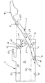
- FIG. 1 shows a schematic diagram of a fuel tank 1 of a motor vehicle, not shown.
- a container wall 2 of the fuel tank 1 Through a container wall 2 of the fuel tank 1 is a section 4 of a filler pipe in an opening 3 5 passed through.
- the filling opening 7 is an outlet opening at a lower end 10 of the filler tube 5 11 flow-favorably on a bottom 12 of the fuel tank 1 educated.
- a bypass or additional line 15 connected to the filler tube 5.
- an outlet opening 17 is provided at the free end 16 of the additional line 15 .
- the outlet opening 17 or the valve 19 of the Additional line 15 are in the embodiment shown in the figure above a maximum fuel level 20.
- the outlet opening 17 of the additional line 15 below or at the level of the maximum fuel level 20.
- Above the maximum fuel level 20 is a compensation volume in the fuel tank 1 21 provided.
- the compensation volume 21 formed outside of the fuel tank 1.
- the in the compensation volume 21 accumulating fuel vapors are drawn in the direction of the Arrow 22 outwards, for example to an activated carbon canister or the like.
- the fuel 23 indicated by arrows flows with an empty fuel tank 1 at an inlet opening 24 of the additional line 15 over without fuel flowing through the additional line 15.
- a certain Filling level 25 which is shown in the figure as a dash-dotted line is on the outlet opening 11 of the lower section 4 of the filler pipe 5 acting fluid pressure so great that the valve 18 closes and the fuel 23 flows into the fuel tank 1 via the additional line 15.
- the valve 19 of the Additional line 15 is designed so that the valve 19 when reaching the maximum Fuel level 20 closes immediately.
- the opening pressure at least the lower valve 18 is set as low as possible, so that an early shutdown the nozzle 9 is excluded due to a fuel 23 flowing back is.
- the opening pressure of the upper valve 19 is Additional line 15 in the order of the static liquid pressure, at which the lower valve 18 is closed.
- the two valves 18, 19 have the same opening pressure, so that the Fuel 23 at least partially at the same time via the two lines or pipes 4, 15 can flow into the fuel tank 1.
- valves are used to achieve a position-independent installation of the valves 18, 19 usually spring-loaded.
- the valve closing body of the valves 18, 19 can be used as one Sphere, a cone or be formed as a flap by the corresponding Spring is applied.
- the valve is 19th the additional line 15 is designed as a float valve.
Landscapes
- Engineering & Computer Science (AREA)
- Life Sciences & Earth Sciences (AREA)
- Sustainable Development (AREA)
- Sustainable Energy (AREA)
- Chemical & Material Sciences (AREA)
- Combustion & Propulsion (AREA)
- Transportation (AREA)
- Mechanical Engineering (AREA)
- Cooling, Air Intake And Gas Exhaust, And Fuel Tank Arrangements In Propulsion Units (AREA)
Description
Die Erfindung betrifft einen Kraftstoffbehälter für ein Kraftfahrzeug gemäß dem Oberbegriff des Anspruchs 1, welcher auf der GB-A-2 283 011 basiert.The invention relates to a fuel tank for a motor vehicle according to the The preamble of claim 1, which is based on GB-A-2 283 011.
In einigen Ländern ist es gesetzlich vorgeschrieben, daß aus dem Einfüllrohr eines Kraftstoffbehälters während der Betankung keine Kraftstoffdämpfe austreten dürfen. Dies kann beispielsweise durch eine Flüssigkeitsabdichtung erreicht werden, bei der ein Höhenunterschied zwischen dem Kraftstoffbehälter und einer Befüllöffnung des Einfüllrohres ausreichend groß ist, so daß der im Kraftstoffbehälter auf die behälterseitige Öffnung des Einfüllrohres wirkende statische Flüssigkeitsdruck bis zum Erreichen einer maximalen Füllstandshöhe überwunden werden kann. Ist der Höhenunterschied zu gering und/oder das Einfüllrohr zu kurz und/oder baut der Kraftstoffbehälter zu flach, so verhindert der im Kraftstoffbehälter auf die Öffnung des Einfüllrohres wirkende Flüssigkeitsdruck, daß der Kraftstoffbehälter vollständig betankbar ist.In some countries it is a legal requirement that a No fuel vapors may escape during the refueling. This can be achieved, for example, with a liquid seal, where there is a height difference between the fuel tank and a fill opening of the filler pipe is large enough so that it is in the fuel tank static liquid pressure acting on the tank-side opening of the filler pipe can be overcome until a maximum fill level is reached. is the height difference too small and / or the filler pipe too short and / or builds the If the fuel tank is too flat, this prevents the fuel tank from opening of the filler pipe acting fluid pressure that the fuel tank completely is refuelable.
Aufgabe der Erfindung ist es, einen Kraftstoffbehälter für ein Kraftfahrzeug zu schaffen, der immer vollständig betankbar ist, ohne daß Kraftstoffdämpfe während der Betankung aus dem Einfüllrohr des Kraftstoffbehälters entweichen.The object of the invention is to provide a fuel tank for a motor vehicle create that is always fully refuelable without fuel vapors during the refueling escape from the filler pipe of the fuel tank.
Diese Aufgabe wird durch die Merkmale des Anspruchs 1 gelöst.This object is solved by the features of claim 1.
Der erfindungsgemäße Kraftstoffbehälter ermöglicht durch die Ausbildung einer Bypass- oder Zusatzleitung an einem bis zum Boden des Kraftstoffbehälters verlängerten Einfüllrohr, daß bei der Betankung der Kraftstoff über die Zusatzleitung in den Kraftstoffbehälter fließen kann, wenn der auf die behälterseitige Öffnung des Einfüllrohres wirkende Flüssigkeitsdruck zu hoch ist. Vorteilhafterweise ist die Zusatzleitung an der höchstmöglichen Stelle des behälterseitigen Abschnittes des Einfüllrohres angeordnet. Die jeweilige Austrittsöffnung des Einfüllrohres bzw. der Zusatzleitung ist mit einem schnellschließenden Ventil versehen, das bereits bei einem geringen Druck öffnet. Dadurch wird zum einen ein Zurückschwappen von Kraftstoff zur Befüllöffnung des Einfüllrohres verhindert und gleichzeitig wird zum anderen der Druckverlust zum Öffnen des Ventils beim Betankungsvorgang minimiert. Die Ventile sind vorteilhafterweise mit einem federbelasteten Ventilschließkörper versehen. Dabei kann der Ventilschließkörper als Kugel, Kegel oder als Klappe ausgebildet sein. Durch die Verwendung eines federbelasteten Ventilschließkörpers ist der Einbau des Ventils lageunabhängig. Bei einer weiteren vorteilhaften Ausführungsform ist das Ventil der Zusatzleitung mit einem Schwimmer versehen, der bei Erreichen der maximalen Füllstandshöhe ausreichend schnell die Öffnung der Zusatzleitung verschließt.The fuel tank according to the invention enables by the formation of a Bypass or additional line on an extended to the bottom of the fuel tank Filler tube that when refueling the fuel through the auxiliary line can flow into the fuel tank if the on the tank side opening the liquid pressure acting on the filler pipe is too high. Advantageously, the Auxiliary line at the highest possible point of the section of the container Filler tube arranged. The respective outlet opening of the filler pipe or Auxiliary line is provided with a quick-closing valve that is already at a little pressure opens. On the one hand, this causes a sloshing back of Prevents fuel to fill the filler tube and at the same time becomes others minimized the pressure loss to open the valve during the refueling process. The valves are advantageously with a spring-loaded valve closing body Mistake. The valve closing body as a ball, cone or as Flap be formed. By using a spring-loaded valve closing body the installation of the valve is independent of the position. Another advantageous The embodiment is the valve of the additional line with a float provided that quickly enough when the maximum fill level is reached The opening of the additional line is closed.
Eine Ausführungsform der Erfindung wird nachstehend anhand der einzigen Figur
beispielshalber beschrieben. Die Figur zeigt eine Prinzipdarstellung eines Kraftstoffbehälters
1 eines nicht dargestellten Kraftfahrzeuges. Durch eine Behälterwand
2 des Kraftstoffbehälters 1 ist in einer Öffnung 3 ein Abschnitt 4 eines Einfüllrohres
5 hindurchgeführt. An einem oberen, in der Nähe der Außenhaut des
Kraftfahrzeuges ausgebildeten Ende 6 des Einfüllrohres 5 ist eine mit einem nicht
dargestellten Deckel verschließbare Öffnung 7 vorgesehen. In diese Öffnung 7 ragt
beim Betankungsvorgang das Rohr 8 einer Zapfpistole 9. Gegenüberliegend zu
der Befüllöffnung 7 ist an einem unteren Ende 10 des Einfüllrohres 5 eine Austrittsöffnung
11 strömungsgünstig an einem Boden 12 des Kraftstoffbehälters 1
ausgebildet. An der höchstmöglichen Stelle 13 des sich in dem Innenraum 14 befindlichen
Abschnittes 4 des Einfüllrohres 5 ist eine Bypass- oder Zusatzleitung 15
an dem Einfüllrohr 5 angeschlossen. An dem freien Ende 16 der Zusatzleitung 15
ist eine Austrittsöffnung 17 vorgesehen. In den beiden Austrittsöffnungen 11, 17 ist
jeweils ein Ventil 18, 19 angeordnet. Die Austrittsöffnung 17 bzw. das Ventil 19 der
Zusatzleitung 15 befinden sich in der in der Figur gezeigten Ausführungsform
oberhalb eines maximalen Kraftstoff-Füllstandes 20. In einer anderen
Ausführungsform kann die Austrittsöffnung 17 der Zusatzleitung 15 unterhalb oder
in der Höhe des maximalen Kraftstoff-Füllstandes 20 liegen. Oberhalb des
maximalen Kraftstoff-Füllstandes 20 ist im Kraftstoffbehälter 1 ein Ausgleichsvolumen
21 vorgesehen. In einer anderen Ausführungsform ist das Ausgleichsvolumen
21 außerhalb des Kraftstoffbehälters 1 ausgebildet. Die in dem Ausgleichsvolumen
21 sich ansammelnden Kraftstoffdämpfe werden in Richtung des eingezeichneten
Pfeiles 22 nach außen, beispielsweise zu einem Aktivkohlebehälter
oder dergleichen, abgeführt.An embodiment of the invention is described below with reference to the single figure
described as an example. The figure shows a schematic diagram of a fuel tank
1 of a motor vehicle, not shown. Through a
Beim Betankungsvorgang strömt der durch Pfeile gekennzeichnete Kraftstoff 23
bei einem leeren Kraftstoffbehälter 1 an einer Eintrittsöffnung 24 der Zusatzleitung
15 vorbei, ohne daß Kraftstoff durch die Zusatzleitung 15 fließt. Ab einem bestimmten
Befüllniveau 25, das in der Figur als eine strichpunktierte Linie eingezeichnet
ist, ist der auf die Austrittsöffnung 11 des unteren Abschnittes 4 des Einfüllrohres 5
wirkende Flüssigkeitsdruck so groß, daß das Ventil 18 schließt und der Kraftstoff
23 über die Zusatzleitung 15 in den Kraftstoffbehälter 1 fließt. Das Ventil 19 der
Zusatzleitung 15 ist so ausgelegt, daß das Ventil 19 beim Erreichen der maximalen
Kraftstoff-Füllstandshöhe 20 sofort schließt. Der Öffnungsdruck zumindest des
unteren Ventils 18 ist so gering wie möglich eingestellt, so daß ein vorzeitiges Abschalten
der Zapfpistole 9 aufgrund eines zurückfließenden Kraftstoffes 23 ausgeschlossen
ist. In der Regel liegt der Öffnungsdruck des oberen Ventils 19 der
Zusatzleitung 15 in der Größenordnung des statischen Flüssigkeitsdruckes, bei
dem das untere Ventil 18 geschlossen wird. In einer anderen Ausführungsform
weisen die beiden Ventile 18, 19 den gleichen Öffnungsdruck auf, so daß der
Kraftstoff 23 zumindest teilweise gleichzeitig über die beiden Leitungen bzw. Rohre
4, 15 in den Kraftstoffbehälter 1 fließen kann.During the refueling process, the
Zur Erreichen eines lageunabhängigen Einbaus der Ventile 18, 19 sind die Ventile
in der Regel federbelastet. Der Ventilschließkörper der Ventile 18, 19 kann als eine
Kugel, ein Kegel oder als eine Klappe ausgebildet sein, der von der entsprechenden
Feder beaufschlagt wird. In einer anderen Ausführungsform ist das Ventil 19
der Zusatzleitung 15 als ein Schwimmerventil ausgebildet.The valves are used to achieve a position-independent installation of the
Claims (4)
- A fuel tank for a motor vehicle, with a filler tube, in which the filler tube has a filling opening at its bodywork side end and in which at its opposite end to this an outlet opening is formed, in which the height difference between the filling opening of the filler tube and a maximum fuel filling level in the fuel tank is so small that the static fluid pressure acting on the outlet opening of the filler tube would prevent complete filling of the fuel tank, and in which the filler tube (5) has an extended section (4) and an outlet opening (11) provided with a valve (18) is formed at the end (10) of the section (4),
characterised in that at least one additional pipe (15) is connected to the section (4) of the filler tube (5) positioned in the interior of the fuel tank (1), in which the outlet opening of the additional pipe (15) in question is provided with a valve (19). - A fuel tank according to Claim 1,
characterised in that the additional pipe (15) is connected at the highest possible position of the section (4) of the filler tube (5). - A fuel tank according to Claim 1 or Claim 2,
characterised in that the valves (18, 19) have a spring loaded valve closing element and that the valve closing element is formed as a ball or a cone or a flap. - A fuel tank according to Claim 1 or Claim 2,
characterised in that the closing of the valve (19) of the additional pipe (15) is effected by a float.
Applications Claiming Priority (2)
| Application Number | Priority Date | Filing Date | Title |
|---|---|---|---|
| DE19743487 | 1997-10-01 | ||
| DE19743487A DE19743487A1 (en) | 1997-10-01 | 1997-10-01 | Fuel tank for a motor vehicle |
Publications (2)
| Publication Number | Publication Date |
|---|---|
| EP0906844A1 EP0906844A1 (en) | 1999-04-07 |
| EP0906844B1 true EP0906844B1 (en) | 2002-03-20 |
Family
ID=7844347
Family Applications (1)
| Application Number | Title | Priority Date | Filing Date |
|---|---|---|---|
| EP98117438A Expired - Lifetime EP0906844B1 (en) | 1997-10-01 | 1998-09-15 | Fuel tank for a motor vehicle |
Country Status (2)
| Country | Link |
|---|---|
| EP (1) | EP0906844B1 (en) |
| DE (2) | DE19743487A1 (en) |
Families Citing this family (1)
| Publication number | Priority date | Publication date | Assignee | Title |
|---|---|---|---|---|
| DE102014108088A1 (en) * | 2014-06-06 | 2015-12-17 | Reutter Gmbh | Liquid tank of a motor vehicle |
Family Cites Families (4)
| Publication number | Priority date | Publication date | Assignee | Title |
|---|---|---|---|---|
| JPS60161623U (en) * | 1984-04-06 | 1985-10-26 | トヨタ自動車株式会社 | vehicle fuel tank |
| DE3804407A1 (en) * | 1988-02-12 | 1989-08-24 | Audi Ag | FUEL CONTAINER FOR MOTOR VEHICLES |
| GB2283011A (en) * | 1993-10-16 | 1995-04-26 | Rover Group | Tank filler duct |
| DE19540269A1 (en) * | 1995-10-28 | 1997-04-30 | Vdo Schindling | Fuel tank for motor vehicle |
-
1997
- 1997-10-01 DE DE19743487A patent/DE19743487A1/en not_active Withdrawn
-
1998
- 1998-09-15 DE DE59803416T patent/DE59803416D1/en not_active Expired - Lifetime
- 1998-09-15 EP EP98117438A patent/EP0906844B1/en not_active Expired - Lifetime
Also Published As
| Publication number | Publication date |
|---|---|
| DE19743487A1 (en) | 1999-04-08 |
| EP0906844A1 (en) | 1999-04-07 |
| DE59803416D1 (en) | 2002-04-25 |
Similar Documents
| Publication | Publication Date | Title |
|---|---|---|
| DE60203676T2 (en) | Check the ventilation of the fuel tank during refueling | |
| DE3605893A1 (en) | FUEL TANK | |
| EP2103473B1 (en) | Ventilation system for a reduction agent container | |
| DE3527773A1 (en) | DEVICE FOR REFUELING FUEL TANKS OF MOTOR VEHICLES, IN PARTICULAR MOTORCYCLES | |
| AT406953B (en) | DEVICE FOR CONTROLLING FLOW FLOWS WHEN REFUELING | |
| EP0320643A2 (en) | Fuel tank | |
| DE19836104A1 (en) | Filling tube for motor vehicle fuel tank | |
| WO2017072135A1 (en) | Fuel container with inlet check valve | |
| DE3602101C2 (en) | Filler neck for a reserve canister for unleaded petrol | |
| DE10110189B4 (en) | Fuel tank | |
| EP0906844B1 (en) | Fuel tank for a motor vehicle | |
| AT408970B (en) | DEVICE FOR PREVENTING OVERFILLING OF A FUEL TANK | |
| EP2883733B1 (en) | Tank system for a vehicle | |
| DE10137986C2 (en) | Ventilation device for a fuel tank | |
| DE3825418C2 (en) | ||
| EP1154909B1 (en) | Valve and fuel tank provided with a valve for a motor vehicle | |
| DE19500775C1 (en) | Device for ventilating and bleeding vehicle fuel tanks | |
| DE19852156C1 (en) | Apparatus for removing gaseous and liquid media from incoming media, especially in a tank deaerator | |
| DE102005053815A1 (en) | De-aeration unit for aerating and de-aerating e.g. liquid fuel tank, has supply port connected with activated carbon filter, and bypass line discharging fuel to de-aeration pipe, where throttle is provided in bypass line | |
| DE19543937C2 (en) | Ventilation device for fuel tanks of motor vehicles | |
| AT405643B (en) | DEVICE FOR PREVENTING OVERFILLING OF A FUEL TANK | |
| EP0763441B1 (en) | Venting arrangement for a fuel tank of a motor vehicle | |
| DE102006056707B4 (en) | Reductant tank and reducing agent arrangement for filling and / or refilling of reducing agent | |
| DE10331395B4 (en) | Fuel tank and venting device therefor | |
| DE102005053816A1 (en) | Ventilation system for fuel tank, has bypass means, by which fuel vapors discharged from inside of fuel tank can be fed into filling-breather line whereby operating-breather line at upper end discharges into ventilation unit |
Legal Events
| Date | Code | Title | Description |
|---|---|---|---|
| PUAI | Public reference made under article 153(3) epc to a published international application that has entered the european phase |
Free format text: ORIGINAL CODE: 0009012 |
|
| 17P | Request for examination filed |
Effective date: 19990128 |
|
| AK | Designated contracting states |
Kind code of ref document: A1 Designated state(s): DE FR GB IT |
|
| AX | Request for extension of the european patent |
Free format text: AL;LT;LV;MK;RO;SI |
|
| AKX | Designation fees paid |
Free format text: DE FR GB IT |
|
| GRAG | Despatch of communication of intention to grant |
Free format text: ORIGINAL CODE: EPIDOS AGRA |
|
| GRAG | Despatch of communication of intention to grant |
Free format text: ORIGINAL CODE: EPIDOS AGRA |
|
| GRAH | Despatch of communication of intention to grant a patent |
Free format text: ORIGINAL CODE: EPIDOS IGRA |
|
| 17Q | First examination report despatched |
Effective date: 20010828 |
|
| GRAH | Despatch of communication of intention to grant a patent |
Free format text: ORIGINAL CODE: EPIDOS IGRA |
|
| REG | Reference to a national code |
Ref country code: GB Ref legal event code: IF02 |
|
| GRAA | (expected) grant |
Free format text: ORIGINAL CODE: 0009210 |
|
| AK | Designated contracting states |
Kind code of ref document: B1 Designated state(s): DE FR GB IT |
|
| REF | Corresponds to: |
Ref document number: 59803416 Country of ref document: DE Date of ref document: 20020425 |
|
| GBT | Gb: translation of ep patent filed (gb section 77(6)(a)/1977) |
Effective date: 20020524 |
|
| ET | Fr: translation filed | ||
| PLBE | No opposition filed within time limit |
Free format text: ORIGINAL CODE: 0009261 |
|
| STAA | Information on the status of an ep patent application or granted ep patent |
Free format text: STATUS: NO OPPOSITION FILED WITHIN TIME LIMIT |
|
| 26N | No opposition filed |
Effective date: 20021223 |
|
| REG | Reference to a national code |
Ref country code: FR Ref legal event code: PLFP Year of fee payment: 18 |
|
| PGFP | Annual fee paid to national office [announced via postgrant information from national office to epo] |
Ref country code: GB Payment date: 20150924 Year of fee payment: 18 |
|
| PGFP | Annual fee paid to national office [announced via postgrant information from national office to epo] |
Ref country code: FR Payment date: 20150928 Year of fee payment: 18 |
|
| PGFP | Annual fee paid to national office [announced via postgrant information from national office to epo] |
Ref country code: IT Payment date: 20150924 Year of fee payment: 18 |
|
| PGFP | Annual fee paid to national office [announced via postgrant information from national office to epo] |
Ref country code: DE Payment date: 20150919 Year of fee payment: 18 |
|
| REG | Reference to a national code |
Ref country code: DE Ref legal event code: R119 Ref document number: 59803416 Country of ref document: DE |
|
| GBPC | Gb: european patent ceased through non-payment of renewal fee |
Effective date: 20160915 |
|
| REG | Reference to a national code |
Ref country code: FR Ref legal event code: ST Effective date: 20170531 |
|
| PG25 | Lapsed in a contracting state [announced via postgrant information from national office to epo] |
Ref country code: FR Free format text: LAPSE BECAUSE OF NON-PAYMENT OF DUE FEES Effective date: 20160930 Ref country code: GB Free format text: LAPSE BECAUSE OF NON-PAYMENT OF DUE FEES Effective date: 20160915 Ref country code: DE Free format text: LAPSE BECAUSE OF NON-PAYMENT OF DUE FEES Effective date: 20170401 |
|
| PG25 | Lapsed in a contracting state [announced via postgrant information from national office to epo] |
Ref country code: IT Free format text: LAPSE BECAUSE OF NON-PAYMENT OF DUE FEES Effective date: 20160915 |