EP2807986A1 - Verfahren zum zuführen eines kryogenen wirkstoffes zu einem kryogenen instrument und kryochirurgische vorrichtung zur durchführung des verfahrens - Google Patents
Verfahren zum zuführen eines kryogenen wirkstoffes zu einem kryogenen instrument und kryochirurgische vorrichtung zur durchführung des verfahrens Download PDFInfo
- Publication number
- EP2807986A1 EP2807986A1 EP20130740514 EP13740514A EP2807986A1 EP 2807986 A1 EP2807986 A1 EP 2807986A1 EP 20130740514 EP20130740514 EP 20130740514 EP 13740514 A EP13740514 A EP 13740514A EP 2807986 A1 EP2807986 A1 EP 2807986A1
- Authority
- EP
- European Patent Office
- Prior art keywords
- cryogenic
- agent
- instrument
- loop
- main line
- Prior art date
- Legal status (The legal status is an assumption and is not a legal conclusion. Google has not performed a legal analysis and makes no representation as to the accuracy of the status listed.)
- Withdrawn
Links
- 238000000034 method Methods 0.000 title claims abstract description 29
- 239000007788 liquid Substances 0.000 claims abstract description 26
- 239000007791 liquid phase Substances 0.000 claims description 19
- 239000012071 phase Substances 0.000 claims description 13
- 239000003795 chemical substances by application Substances 0.000 abstract description 170
- IJGRMHOSHXDMSA-UHFFFAOYSA-N Atomic nitrogen Chemical compound N#N IJGRMHOSHXDMSA-UHFFFAOYSA-N 0.000 abstract description 20
- 229910052757 nitrogen Inorganic materials 0.000 abstract description 10
- 239000003814 drug Substances 0.000 abstract description 3
- 239000007789 gas Substances 0.000 description 14
- 238000010792 warming Methods 0.000 description 8
- 238000009835 boiling Methods 0.000 description 7
- 238000001356 surgical procedure Methods 0.000 description 6
- 238000002360 preparation method Methods 0.000 description 5
- 239000007921 spray Substances 0.000 description 5
- 238000001816 cooling Methods 0.000 description 4
- 238000007710 freezing Methods 0.000 description 4
- 230000008014 freezing Effects 0.000 description 4
- 239000003570 air Substances 0.000 description 3
- 230000001276 controlling effect Effects 0.000 description 2
- 230000006378 damage Effects 0.000 description 2
- 238000010586 diagram Methods 0.000 description 2
- 238000009413 insulation Methods 0.000 description 2
- 239000012080 ambient air Substances 0.000 description 1
- 238000002681 cryosurgery Methods 0.000 description 1
- 238000006073 displacement reaction Methods 0.000 description 1
- 238000001704 evaporation Methods 0.000 description 1
- 230000008020 evaporation Effects 0.000 description 1
- 239000001307 helium Substances 0.000 description 1
- 229910052734 helium Inorganic materials 0.000 description 1
- SWQJXJOGLNCZEY-UHFFFAOYSA-N helium atom Chemical compound [He] SWQJXJOGLNCZEY-UHFFFAOYSA-N 0.000 description 1
- 238000005086 pumping Methods 0.000 description 1
- 230000001105 regulatory effect Effects 0.000 description 1
- 230000003584 silencer Effects 0.000 description 1
- 238000005507 spraying Methods 0.000 description 1
Images

Classifications
-
- A—HUMAN NECESSITIES
- A61—MEDICAL OR VETERINARY SCIENCE; HYGIENE
- A61B—DIAGNOSIS; SURGERY; IDENTIFICATION
- A61B18/00—Surgical instruments, devices or methods for transferring non-mechanical forms of energy to or from the body
- A61B18/02—Surgical instruments, devices or methods for transferring non-mechanical forms of energy to or from the body by cooling, e.g. cryogenic techniques
-
- A—HUMAN NECESSITIES
- A61—MEDICAL OR VETERINARY SCIENCE; HYGIENE
- A61B—DIAGNOSIS; SURGERY; IDENTIFICATION
- A61B18/00—Surgical instruments, devices or methods for transferring non-mechanical forms of energy to or from the body
- A61B2018/00005—Cooling or heating of the probe or tissue immediately surrounding the probe
- A61B2018/00041—Heating, e.g. defrosting
-
- A—HUMAN NECESSITIES
- A61—MEDICAL OR VETERINARY SCIENCE; HYGIENE
- A61B—DIAGNOSIS; SURGERY; IDENTIFICATION
- A61B18/00—Surgical instruments, devices or methods for transferring non-mechanical forms of energy to or from the body
- A61B2018/00636—Sensing and controlling the application of energy
- A61B2018/00696—Controlled or regulated parameters
- A61B2018/00744—Fluid flow
-
- A—HUMAN NECESSITIES
- A61—MEDICAL OR VETERINARY SCIENCE; HYGIENE
- A61B—DIAGNOSIS; SURGERY; IDENTIFICATION
- A61B18/00—Surgical instruments, devices or methods for transferring non-mechanical forms of energy to or from the body
- A61B18/02—Surgical instruments, devices or methods for transferring non-mechanical forms of energy to or from the body by cooling, e.g. cryogenic techniques
- A61B2018/0231—Characteristics of handpieces or probes
- A61B2018/0262—Characteristics of handpieces or probes using a circulating cryogenic fluid
-
- A—HUMAN NECESSITIES
- A61—MEDICAL OR VETERINARY SCIENCE; HYGIENE
- A61B—DIAGNOSIS; SURGERY; IDENTIFICATION
- A61B90/00—Instruments, implements or accessories specially adapted for surgery or diagnosis and not covered by any of the groups A61B1/00 - A61B50/00, e.g. for luxation treatment or for protecting wound edges
- A61B90/06—Measuring instruments not otherwise provided for
- A61B2090/064—Measuring instruments not otherwise provided for for measuring force, pressure or mechanical tension
- A61B2090/065—Measuring instruments not otherwise provided for for measuring force, pressure or mechanical tension for measuring contact or contact pressure
Definitions
- the invention relates to the field of medicine, specifically to methods for feeding a cryogenic agent to cryogenic instruments as well as to a cryosurgical equipment, and can be used for cooling and destruction of pathologically changed areas of biological tissues.
- the invention relates to methods for feeding a cryogenic agent to a cryogenic instrument.
- the prior art comprises a variety of methods for feeding a cryogenic agent to a cryogenic instrument. It is known a method for feeding a cryogenic agent to a cryogenic instrument which includes connecting of the cryogenic instrument to a reservoir with a cryogenic agent via a cryogenic conduit, wherein the cryogenic agent is fed from the reservoir to the cryogenic instrument via the cryogenic conduit, for this purpose the cryogenic agent is fed to the cryogenic instrument under pressure. (See description to the USSR patent No 1102096, published on January 11, 1983 )
- the drawback of the above method is that it does not allow for keeping a long distance between the cryogenic instrument and the reservoir with the cryogenic agent while maintaining low temperature, due to the fact that the more is the pressure in the cryogenic conduit required to feed the cryogenic agent on a longer distance, the higher is the boiling point of cryogenic agent.
- the minimum temperature that can be maintained using the above method for feeding the cryogenic agent with the help of liquid nitrogen is - 185°C.
- the drawback of the above method is that it does not allow for keeping a long distance between the cryogenic instrument and the reservoir with the cryogenic agent. This limits the scope of application of the cryosurgical apparatus and reduces its operating efficiency. This is attributable to the fact that the cryogenic agent starts boiling inside the cryogenic conduit, if the length of the latter is increased. Such phenomenon ultimately reduces the operating efficiency as it prevents attaining low temperatures inside the cryogenic instrument and makes the cooling of the same less efficient. However, a shorter cryogenic conduit means a more difficult manipulation of the cryogenic instrument during surgeries.
- the invention relates to the field of medicine, specifically to methods for feeding a cryogenic agent to a cryogenic instrument, wherein one connects the cryogenic instrument to a reservoir with the cryogenic agent via a cryogenic conduit and feeds the cryogenic agent from the reservoir to the cryogenic instrument via the cryogenic conduit.
- the claimed invention has the following technical objective, i.e. to increase the distance over which it is possible to feed the cryogenic agent to the cryogenic instrument from the reservoir with the cryogenic agent while keeping the cryogenic instrument at a low temperature.
- the invention is described herein with the primary aim to offer a method for feeding a cryogenic agent to a cryogenic instrument that serves to mitigate the above drawback.
- the method for feeding a cryogenic agent to a cryogenic instrument as described in the above introduction to the general description essentially characterized in that additionally one forms a loop-shaped main line going out and entering into the reservoir with the cryogenic agent, realizes a circulation of the cryogenic agent into the loop-shaped main line, connects the cryogenic instrument to said loop-shaped main line via the cryogenic conduit and feeds through it the cryogenic agent, wherein a flow rate of the cryogenic agent circulated into the loop-shaped main line must be greater than a flow rate of the cryogenic agent entering into the cryogenic instrument via the cryogenic conduit.
- Such method for feeding the cryogenic agent to the cryogenic instrument according to the invention makes it possible to increase the distance over which it is possible to feed the cryogenic agent to the cryogenic instrument from the reservoir with the cryogenic agent while keeping the cryogenic instrument at a low temperature.
- the above feature serves to increase cooling capacity of the cryogenic instrument and, as a result, tissue freezing rate during cryosurgeries.
- a cryogenic agent flow through the cryogenic conduit is determined by the capacity of the pipeline which depends on the pressure difference at the ends of the cryogenic conduit and is in inverse ratio to the length of the cryogenic conduit.
- the pressure difference when operating in underpressure conditions cannot, by definition, be more than 1 atm. Therefore, if we reduce the length of a cryogenic conduit section operating in underpressure conditions (i.e. by using a loop-shaped main line) from 2 to 0,2 meters, we will be able to increase its capacity tenfold.
- cryogenic instruments closed-type (where the cryogenic agent does not come into direct contact with the tissues of the patient under surgery) and open-type (where the cryogenic agent comes into direct contact with the tissues), and a spray nozzle with free discharge of the cryogenic agent from the cryogenic instrument for cryolavage of the patient tissues.
- the invention relates to cryosurgical apparatuses including a reservoir with a cryogenic agent, a cryogenic instrument with a feeding cryoconduit of the cryogenic agent and a draining cryoconduit of the cryogenic agent, an exhaust system of the cryogenic agent connected to the cryogenic instrument via the draining cryoconduit of the cryogenic agent.
- the prior art comprises cryogenic instruments and apparatuses for local tissue freezing.
- a known example of the prior art is a cryosurgical apparatuses including a reservoir with a cryogenic agent, a cryogenic instrument with a feeding cryoconduit of the cryogenic agent and a draining cryoconduit of the cryogenic agent (See the USSR patent No 1102096, published on January 11, 1983 ), wherein cryogenic agent is fed to the cryogenic instrument under pressurized gas.
- the drawback of the above method is that it does not allow to attain low temperature due to the fact that the more is the pressure, the higher is the boiling point of cryogenic agent. If liquid nitrogen is used as cryogenic agent, the minimum temperature delivered by said apparatus is -185 °C.
- the cryogenic agent is fed to the cryogenic instrument by using a vacuum pump-based exhaust system to generate vacuum in the cryogenic instrument itself.
- the drawback of the above method is that it does not allow for keeping a long distance between the cryogenic instrument and the reservoir with the cryogenic agent. This limits the scope of the cryosurgical apparatus and reduces its operating efficiency. This is attributable to the fact that the cryogenic agent starts boiling inside the cryogenic conduit, if the length of the latter is increased, which ultimately reduces operating efficiency. A shorter cryogenic conduit means a more difficult manipulation of the cryogenic instrument during surgeries.
- the invention claimed has the following technical objective, i.e. to increase the operating efficiency of the cryosurgical apparatus, namely: the possibility of achieving temperatures as low as -200 and -210°C when using liquid nitrogen as cryogenic agent and with a significant distance between the cryogenic instrument and the cryogenic agent-containing reservoir.
- the cryosurgical apparatus as described in the above introduction to the general description essentially characterizes in that the cryosurgical apparatus has a loop-shaped main line where circulates the cryogenic agent, an inlet and an outlet of the loop-shaped main line being connected to the reservoir with the cryogenic agent. Said loop-shaped main line has at least one bend for connecting to the cryogenic instrument via the feeding cryoconduit of the cryogenic agent.
- Such structure of the cryosurgical apparatus according to the invention is more efficient in use as it makes it possible to attain a lower temperature of cryogenic agent in the cryogenic instrument and to considerably increase the distance between the cryogenic instrument from the cryogenic agent-containing reservoir.
- Another technical result of the invention is the option to use the cryosurgical apparatus in various modes, including one non-operating mode and five operating modes.
- Said cryogenic apparatus allows to use a variety of cryogenic instruments: closed-type (where the cryogenic agent does not come into direct contact with the tissues of the patient under surgery) and open-type (where the cryogenic agent comes into direct contact with the tissues), for this purpose, open-type cryogenic instruments may involve free discharge of the cryogenic agent from the cryogenic instrument (if spray nozzle in cryolavage mode is used as a cryogenic instrument) or may come without such option (if the open-type cryogenic instrument is pressed to the tissues under treatment).
- closed-type where the cryogenic agent does not come into direct contact with the tissues of the patient under surgery
- open-type cryogenic instruments may involve free discharge of the cryogenic agent from the cryogenic instrument (if spray nozzle in cryolavage mode is used as a cryogenic instrument) or may come without such option (if the open-type cryogenic instrument is pressed to the tissues under treatment).
- the cryosurgical apparatus has a loop-shaped main line which enters and exits the cryogenic agent-containing reservoir, circulating the cryogenic agent.
- Said main line has at least one bend to connect to the cryosurgical apparatus via the cryogenic agent feeding cryoconduit.
- the inlet of the loop-shaped main line is connected to an outlet of an intake switch of a liquid or a gas phase of the cryogenic agent into the reservoir, while an inlet of the intake switch of the gas phase is connected to a section of the reservoir which contains the gas phase of the cryogenic agent and an inlet of the intake switch of the liquid phase is connected to a section of the reservoir which contains the liquid phase of the cryogenic agent.
- the above feature ensures accelerated warming of the cryogenic instrument.
- the loop-shaped main line where circulates the cryogenic agent principally includes at least one feeding pump.
- the above feature makes it possible to circulate the cryogenic agent in the loop-shaped main line in addition to feeding the same to the cryogenic instrument.
- Said feeding pump enables feeding the cryogenic agent to several cryogenic instruments connected to the loop-shaped main line.
- the loop-shaped main line where circulates the cryogenic agent includes at least one first controller of a cryogenic agent flow rate.
- the inclusion of the first controller of the flow rate makes it possible to select a most saving mode when connecting various open- or closed- type cryogenic instruments.
- the loop-shaped main line where circulates the cryogenic agent includes at least one controller of a cryogenic agent pressure.
- the inclusion of the controller of the cryogenic agent pressure makes it possible to feed the cryogenic agent to the cryogenic instrument at required pressure in required operating modes of the cryogenic instrument.
- the loop-shaped main line where circulates the cryogenic agent includes at least a sensor of the cryogenic agent pressure.
- the inclusion of the first sensor of the cryogenic agent pressure makes it possible to add a system for control and regulation of the cryosurgical apparatus.
- the loop-shaped main line where circulates the cryogenic agent includes at least one sensor of a cryogenic agent liquid phase in the closed main line.
- the above feature makes it possible to control the completion of preparation of the cryogenic apparatus for operation.
- the feeding cryoconduit of the cryogenic agent from the loop-shaped main line to the cryogenic instrument includes at least one clack valve of the cryoconduit.
- the above feature makes it possible to prevent leakage of the gas phase from the cryogenic instrument to the loop-shaped main line or ambient air leaks.
- the feeding cryoconduit of the cryogenic agent from the loop-shaped main line to the cryogenic instrument includes at least one shutoff valve.
- Said valve has two positions: “open” and “closed”. If the valve is in the "open” position, the cryogenic agent is fed to the cryogenic instrument. If the valve is in the "closed” position, the cryogenic agent is not fed to the cryogenic instrument.
- the above feature makes it possible to prevent cryogenic agent leaks from the cryogenic conduit and the loop-shaped main line in the mode for preparation of the cryosurgical apparatus for operation and during cryogenic instrument change when the cryosurgical apparatus is in an operating mode.
- the feeding cryoconduit of the cryogenic agent from the loop-shaped main line to the cryogenic instrument includes at least one first heater of the cryogenic agent.
- the inclusion of the first heater enables forced accelerated warming of the cryogenic instrument.
- the feeding cryoconduit of the cryogenic agent from the loop-shaped main line to the cryogenic instrument includes at least one first sensor of temperature of the cryogenic agent.
- the inclusion of the first sensor of temperature of the cryogenic agent makes it possible to control and regulate the cryogenic apparatus in operating modes.
- the feeding cryoconduit of the cryogenic agent from the loop-shaped main line to the cryogenic instrument includes at least one plug connection.
- the above feature enables connection of various cryogenic instruments.
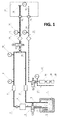
- a cryosurgical apparatus comprises a reservoir 1 with a cryogenic agent, a liquid cryogenic agent level indicator 2, a gas phase cryogenic agent intake 3, a liquid phase cryogenic agent intake 4, a valve 5, i.e. a switch of liquid-to-gas phase of the cryogenic agent, a feeding pump 6, a clack valve of the loop-shaped main line 7, a flow rate controller 8, a pressure sensor 9, a sensor 10 of the cryogenic agent liquid phase in the loop-shaped main line, a bend 11 for feeding the cryogenic agent from the loop-shaped main line to the cryogenic instrument, a clack valve 12 of the cryoconduit, a shutoff valve 13, a first cryogenic agent heater 14, a first temperature sensor 15 of the fed cryogenic agent, a plug connection 16, a cryogenic instrument 17 including a nozzle 18 spraying the cryogenic agent and a second temperature sensor 19 in the cryogenic instrument, a third temperature sensor in a draining cryoconduit 20, a second cryogenic agent heater 21, a vacuum valve 22, a vacuum sensor 23,
- the loop-shaped main line consists in sections: A (or A1), B, C, D, E, F, G, H, I.
- the cryogenic conduit for feeding cryogenic agent to the cryogenic instrument consists in sections: K, L, M, N, O.
- the cryogenic conduit for draining the gas-liquid phase of the cryogenic agent from the cryogenic instrument consists in sections: P, Q, R, S, T, U, V (or P, Q, R, S1).
- Liquid nitrogen, liquid helium or other varieties of liquefied gas which remain in liquid state at normal air pressure can be used as cryogenic agent.
- a recuperator can be installed to reuse the cryogenic agent.
- a standard Dewar flask can be used as reservoir 1.
- Cryoconduits that may come in contact with the human body are equipped with reinforced thermal insulation (vacuum insulation, thermal blankets, etc), i.e. at any case they have at least two layers.
- the feeding pump can be submerged (placed inside the reservoir 1 below the level of liquid cryogenic agent) or located outside the reservoir 1. Any type of the cryogenic feeding pump can be used, including positive displacement pump (gear pump, plunger pump, etc).
- the feeding pump can be adjustable or non-adjustable. If adjustable feeding pump is used (i.e. variable capacity pump), the first flow rate controller 8 is redundant.
- Figure 1 shows an option wherein a two-phase feeding pump 6 is used, i.e. capable of pumping cryogenic agent both in liquid and in gas states, for a more efficient warming.
- Figure 1 also shows an option with a non-adjustable feeding pump 6.
- Sections A(or A1) BCDEFGHI of the main line, the feeding cryoconduit KLMNO and the gas-liquid phase draining cryoconduit PQRSTUV or PQRS1 from the cryogenic instrument may be integrated in a single insulated cryohose (including, in a coaxial way). This option is not shown in the Figure 1 . Said option serves to improve the usability of the cryosurgical apparatus.
- the control and regulation system serves to optimize the cryogenic apparatus operating modes to maintain minimum or predefined temperature and preset cryoexposure time by receiving the signals from the pressure sensor 9, the vacuum sensor 23, the first temperature sensor 15, the second temperature sensor 19, the third temperature sensor 20 and by controlling the operating modes of the feeding pump 6, the first flow rate controller 8, the second (vacuum) flow rate controller 24, the pressure controller 27, the cutoff valve 13, the vacuum valve 22, the first heater 14 and the second heater 21.
- the system is also connected to the liquid cryogenic agent level indicator 2.
- the temperature inside the cryogenic instrument 17 or on its internal surface is measured by the temperature sensor 19.
- the temperature of cryogenic agent in the gas-liquid phase draining cryoconduit is measured by the temperature sensor 20, which transmits a signal to the control and regulation system.
- a signal from the second temperature sensor 19 is used to control the cryogenic instrument operating model, or the third temperature sensor 20, if a cryogenic instrument without a temperature sensor is used. This serves to make the operation more reliable and the cryosurgical apparatus control more accurate as well as to increase functional capabilities of the same.
- the vacuum sensor 23 transmits a signal in accordance with the vacuum level in the draining cryogenic conduit to the control and regulation system.
- the second (vacuum) flow rate controller 24 sets a required mode to exhaust gas from the cryogenic instrument.
- the second heater 21 is designed to preheat the gas-liquid phase fed from the cryogenic instrument to protect the vacuum valve 22, the second (vacuum) flow rate controller 24 and the vacuum pump 25 from contact with liquid cryogenic agent.
- the first flow rate controller 8 can be built as a controller which branches from the loop-shaped main line to drain cryogenic agent right to the reservoir 1. The element is not shown in the drawing.
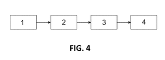
- the Figure 4 demonstrates stages (by numbers) of the procedures for feeding the cryogenic agent to the cryogenic instrument, namely:
- the cryosurgical apparatus operates as follows.
- the liquid cryogenic agent is fed from an external or a built-in reservoir 1 through an intake 4 using the feeding pump 6 of the liquid cryogenic agent to a loop-shaped main line ABCDEFGHI.
- the valve 5, i.e. gas/liquid phase intake switch is in the liquid phase intake position (see Figure 1 ).
- the liquid cryogenic agent level indicator 2 sends a signal corresponding to the cryogenic agent level in the reservoir to the control and regulation system of the cryogenic apparatus.
- the cryogenic agent is fed to the bend 11 through the first flow rate controller 8, is circulated along the loop-shaped main line through the pressure controller 27, and fed back to the reservoir 1.
- the pressure sensor 9 in the incoming section ABCDEFG of the loop-shaped main line sends a signal corresponding to the cryogenic agent pressure to the control and regulation system.
- the liquid phase sensor 10 sends a signal of complete filling of the loop-shaped main line (up to and including the bend 11) by the liquid cryogenic agent.
- the control and regulation system authorizes operating modes of the cryogenic apparatus.
- the feeding pump 6 is on, the shutoff valve 13 is closed, and the cryogenic agent is circulated in the loop-shaped main line.
- the feeding pump 6 is on, the shutoff valve 13 is open (as on the figure 1 ), and the cryogenic agent is fed to the closed-type cryogenic instrument via the feeding cryoconduit.
- the vacuum valve 22 serves to drain the contents of the gas-liquid phase draining cryoconduit to the air (see Figure 1 ).
- the vacuum pump 25 is off.
- the liquid cryogenic agent is fed to the cryogenic instrument 17 and evaporates to cool the cryogenic instrument. Gas phase is emitted to the air through the gas-liquid phase draining cryoconduit.
- cryogenic instrument 17 In the mode 3, i.e. the cryolavage mode or feeding the cryogenic agent to the cryogenic instrument by generating pressure in the feeding cryoconduit for an open-type cryogenic instrument with free discharge of cryogenic agent from the cryogenic instrument, wherein an open-type cryogenic instrument with free discharge of cryogenic agent (a spray nozzle 18) replaces the cryogenic instrument 17.
- the gas-liquid phase draining cryoconduit PQRS1 or PQRSTUV is not involved, and the vacuum pump is not activated.
- the shutoff valve 13 is open, the cryogenic instrument 17 (of the closed-type) is connected to a cryosystem through the plug connection 16.
- the vacuum valve 22 connects the gas-liquid phase draining cryoconduit to the vacuum pump 25.
- the pressure controller 27 is set to zero. Once the vacuum pump is activated, an underpressure is generated inside the cryogenic instrument. Under such conditions, the liquid cryogenic agent is fed from the bend 11 to the cryogenic instrument 17, where it evaporates intensely to cool the surface of the cryogenic instrument.
- the elements of the cryosurgical apparatus are in the same position as in the mode 5. Under such conditions, the liquid cryogenic agent is fed from the bend 11 to the cryogenic instrument 17 of the open-type, where it evaporates intensely to cool the surface of the cryogenic instrument.
- the first heater 14 is activated to evaporate and heat the cryogenic agent to the required temperature.
- the cryogenic instrument is warmed to the temperature, at which adhesion to the surface of the object being cooled is severed and the cryogenic instrument can be removed without damaging the object.
- the valve 5 connects the gas phase intake 3 to the feeding pump 6.
- the gas phase cryogenic agent is fed to the cryogenic system and does not require evaporation by the heater 14, which serves to accelerate and enhance the warming of the cryogenic instrument.
- the proposed method for feeding cryogenic agent to the cryogenic instrument has been tested on the prototype model.
- Liquid nitrogen was used as the cryogenic agent.
- Tests of the prototype model in the mode for cryogenic agent feeding by generating underpressure in the cryogenic instrument showed an increase of the distance over which it is possible to feed the cryogenic agent to the cryogenic instrument from the reservoir with the cryogenic agent while keeping the cryogenic instrument at a low temperature.
- said distance between the cryogenic instrument and the reservoir was increased to 2,5 meters.
- the temperature of - 210°C (boiling point of liquid nitrogen in vacuum) was attained.
- the cryosurgical apparatus proposed is recommended for use in healthcare institutions for cooling and destruction of pathologically changed areas of biological tissues.
Landscapes
- Health & Medical Sciences (AREA)
- Surgery (AREA)
- Life Sciences & Earth Sciences (AREA)
- Nuclear Medicine, Radiotherapy & Molecular Imaging (AREA)
- Medical Informatics (AREA)
- Engineering & Computer Science (AREA)
- Biomedical Technology (AREA)
- Heart & Thoracic Surgery (AREA)
- Otolaryngology (AREA)
- Molecular Biology (AREA)
- Animal Behavior & Ethology (AREA)
- General Health & Medical Sciences (AREA)
- Public Health (AREA)
- Veterinary Medicine (AREA)
- Surgical Instruments (AREA)
- Compressors, Vaccum Pumps And Other Relevant Systems (AREA)
Applications Claiming Priority (3)
| Application Number | Priority Date | Filing Date | Title |
|---|---|---|---|
| EA201200066A EA019280B1 (ru) | 2012-01-26 | 2012-01-26 | Криохирургический аппарат |
| EA201200067A EA019253B1 (ru) | 2012-01-26 | 2012-01-26 | Способ подачи криоагента к криоинструменту |
| PCT/EA2013/000001 WO2013110283A1 (ru) | 2012-01-26 | 2013-01-23 | Способ подачи криоагента к криоинструменту и криохирургический аппарат для его осуществления |
Publications (2)
| Publication Number | Publication Date |
|---|---|
| EP2807986A1 true EP2807986A1 (de) | 2014-12-03 |
| EP2807986A4 EP2807986A4 (de) | 2016-05-04 |
Family
ID=48872887
Family Applications (1)
| Application Number | Title | Priority Date | Filing Date |
|---|---|---|---|
| EP13740514.8A Withdrawn EP2807986A4 (de) | 2012-01-26 | 2013-01-23 | Verfahren zum zuführen eines kryogenen wirkstoffes zu einem kryogenen instrument und kryochirurgische vorrichtung zur durchführung des verfahrens |
Country Status (3)
| Country | Link |
|---|---|
| US (1) | US20150126987A1 (de) |
| EP (1) | EP2807986A4 (de) |
| WO (1) | WO2013110283A1 (de) |
Cited By (2)
| Publication number | Priority date | Publication date | Assignee | Title |
|---|---|---|---|---|
| RU2609056C1 (ru) * | 2015-12-17 | 2017-01-30 | Валентин Николаевич Павлов | Криохирургический аппарат |
| WO2018130096A1 (zh) * | 2017-01-16 | 2018-07-19 | 康沣生物科技(上海)有限公司 | 一种冷冻消融系统 |
Families Citing this family (7)
| Publication number | Priority date | Publication date | Assignee | Title |
|---|---|---|---|---|
| US11633224B2 (en) | 2020-02-10 | 2023-04-25 | Icecure Medical Ltd. | Cryogen pump |
| NL2026770B1 (nl) * | 2020-10-26 | 2022-09-16 | H Harinck Beheer B V | Werkwijze voor toediening van een medium |
| US12426934B2 (en) | 2022-02-28 | 2025-09-30 | Icecure Medical Ltd. | Cryogen flow control |
| US20230381015A1 (en) * | 2022-05-31 | 2023-11-30 | Icecure Medical Ltd. | Cryogenic system with multiple submerged pumps |
| US12215811B2 (en) | 2022-07-18 | 2025-02-04 | Icecure Medical Ltd. | Cryogenic system connector |
| CN116172687B (zh) * | 2023-01-04 | 2024-04-23 | 上海交通大学 | 一种负压调控式冷冻治疗系统以及控制方法 |
| US12527613B2 (en) | 2023-09-11 | 2026-01-20 | Icecure Medical Ltd. | Cryoprobe |
Family Cites Families (16)
| Publication number | Priority date | Publication date | Assignee | Title |
|---|---|---|---|---|
| US4211231A (en) * | 1978-05-15 | 1980-07-08 | Cryomedics, Inc. | Cryosurgical instrument |
| IT1159748B (it) * | 1978-06-23 | 1987-03-04 | Bracco Dario | Apparecchio per crioterapia |
| SU1102096A1 (ru) | 1983-01-11 | 1988-02-15 | Предприятие П/Я Р-6028 | Криохирургический аппарат |
| RU2053719C1 (ru) | 1992-02-03 | 1996-02-10 | Валентин Николаевич Павлов | Криохирургический аппарат |
| GB9506652D0 (en) * | 1995-03-31 | 1995-05-24 | Cryogenic Technology Ltd | Supplying liquid cryogen to cryosurgical apparatus |
| US6569158B1 (en) * | 1999-01-25 | 2003-05-27 | Cryocath Technologies, Inc. | Leak detection system |
| US6471694B1 (en) * | 2000-08-09 | 2002-10-29 | Cryogen, Inc. | Control system for cryosurgery |
| CN1214766C (zh) * | 2002-02-25 | 2005-08-17 | 中国科学院理化技术研究所 | 用于人体腔道肿瘤冷冻治疗的柔性冷刀探针 |
| IL151486A0 (en) * | 2002-08-26 | 2003-04-10 | Levin Alexander | Cryosurgical instrument and its accessory system |
| US7083612B2 (en) * | 2003-01-15 | 2006-08-01 | Cryodynamics, Llc | Cryotherapy system |
| CN2676852Y (zh) * | 2003-09-08 | 2005-02-09 | 中国科学院理化技术研究所 | 用于低温手术中对正常组织进行保护的装置 |
| US7674256B2 (en) * | 2005-03-17 | 2010-03-09 | Boston Scientific Scimed, Inc. | Treating internal body tissue |
| US20080027422A1 (en) * | 2006-07-25 | 2008-01-31 | Ams Research Corporation | Closed-Loop Cryosurgical System and Cryoprobe |
| US20090163902A1 (en) * | 2007-12-21 | 2009-06-25 | Sanarus Medical, Inc. | Cryoprobe With Automatic Purge Bypass Valve |
| US8814850B2 (en) * | 2008-04-24 | 2014-08-26 | Cryomedix, Llc | Method and system for cryoablation treatment |
| US8080005B1 (en) * | 2010-06-10 | 2011-12-20 | Icecure Medical Ltd. | Closed loop cryosurgical pressure and flow regulated system |
-
2013
- 2013-01-23 WO PCT/EA2013/000001 patent/WO2013110283A1/ru not_active Ceased
- 2013-01-23 US US14/366,472 patent/US20150126987A1/en not_active Abandoned
- 2013-01-23 EP EP13740514.8A patent/EP2807986A4/de not_active Withdrawn
Cited By (2)
| Publication number | Priority date | Publication date | Assignee | Title |
|---|---|---|---|---|
| RU2609056C1 (ru) * | 2015-12-17 | 2017-01-30 | Валентин Николаевич Павлов | Криохирургический аппарат |
| WO2018130096A1 (zh) * | 2017-01-16 | 2018-07-19 | 康沣生物科技(上海)有限公司 | 一种冷冻消融系统 |
Also Published As
| Publication number | Publication date |
|---|---|
| EP2807986A4 (de) | 2016-05-04 |
| WO2013110283A1 (ru) | 2013-08-01 |
| US20150126987A1 (en) | 2015-05-07 |
Similar Documents
| Publication | Publication Date | Title |
|---|---|---|
| EP2807986A1 (de) | Verfahren zum zuführen eines kryogenen wirkstoffes zu einem kryogenen instrument und kryochirurgische vorrichtung zur durchführung des verfahrens | |
| JP5490218B2 (ja) | 多管の遠位部を有する単相液体冷媒冷凍アブレーション・システム及び関連する方法 | |
| US11963707B2 (en) | Modular pulsed pressure device for the transport of liquid cryogen to a cryoprobe | |
| US7192426B2 (en) | Cryogenic system | |
| JP7088478B2 (ja) | 冷凍アブレーション装置及び冷凍アブレーション方法 | |
| US7507233B2 (en) | Cryotherapy system | |
| CN103079487B (zh) | 采用单冷冻剂的冷冻外科器械的加热和冷却 | |
| EP2904986B1 (de) | System für kryotherapie | |
| US10182859B2 (en) | Medical device for the transport of subcooled cryogenic fluid through a linear heat exchanger | |
| US11607262B2 (en) | N2O thermal pressurization system by cooling | |
| CN102596119A (zh) | 使用超临界气体的低温治疗装置 | |
| CN102014777A (zh) | 用于冷冻消融治疗的方法和系统 | |
| AU2019342120A1 (en) | Thermal devices and methods of visceral fat reduction | |
| CN207979766U (zh) | 一种冷冻消融系统 | |
| JP2015533314A (ja) | 極低温システムのための装置、プローブおよび方法 | |
| JP2021126513A (ja) | 極低温ポンプ | |
| US20140371733A1 (en) | All-Liquid Cryoablation Catheter | |
| EP1427344B1 (de) | Kryogenes system | |
| RU2609056C1 (ru) | Криохирургический аппарат | |
| RU2624347C1 (ru) | Криомедицинский аппарат | |
| RU2483691C2 (ru) | Криохирургический аппарат | |
| JPH07136181A (ja) | 液体冷媒の供給・排出方法及びその装置 | |
| EA019280B1 (ru) | Криохирургический аппарат | |
| HK1122484A1 (en) | Methods and systems for cryogenic cooling | |
| HK1122484B (en) | Methods and systems for cryogenic cooling |
Legal Events
| Date | Code | Title | Description |
|---|---|---|---|
| PUAI | Public reference made under article 153(3) epc to a published international application that has entered the european phase |
Free format text: ORIGINAL CODE: 0009012 |
|
| 17P | Request for examination filed |
Effective date: 20140623 |
|
| AK | Designated contracting states |
Kind code of ref document: A1 Designated state(s): AL AT BE BG CH CY CZ DE DK EE ES FI FR GB GR HR HU IE IS IT LI LT LU LV MC MK MT NL NO PL PT RO RS SE SI SK SM TR |
|
| DAX | Request for extension of the european patent (deleted) | ||
| RA4 | Supplementary search report drawn up and despatched (corrected) |
Effective date: 20160404 |
|
| RIC1 | Information provided on ipc code assigned before grant |
Ipc: A61B 18/02 20060101AFI20160329BHEP Ipc: F25D 3/10 20060101ALI20160329BHEP |
|
| STAA | Information on the status of an ep patent application or granted ep patent |
Free format text: STATUS: THE APPLICATION IS DEEMED TO BE WITHDRAWN |
|
| 18D | Application deemed to be withdrawn |
Effective date: 20170419 |