EP2807408B1 - Sicherheitskappe - Google Patents
Sicherheitskappe Download PDFInfo
- Publication number
- EP2807408B1 EP2807408B1 EP13702294.3A EP13702294A EP2807408B1 EP 2807408 B1 EP2807408 B1 EP 2807408B1 EP 13702294 A EP13702294 A EP 13702294A EP 2807408 B1 EP2807408 B1 EP 2807408B1
- Authority
- EP
- European Patent Office
- Prior art keywords
- base
- cell
- lock
- wings
- relative
- Prior art date
- Legal status (The legal status is an assumption and is not a legal conclusion. Google has not performed a legal analysis and makes no representation as to the accuracy of the status listed.)
- Not-in-force
Links
- 238000000034 method Methods 0.000 claims description 20
- 230000000881 depressing effect Effects 0.000 claims description 9
- 239000012530 fluid Substances 0.000 claims description 8
- 230000008901 benefit Effects 0.000 description 4
- 230000000994 depressogenic effect Effects 0.000 description 4
- 238000013461 design Methods 0.000 description 4
- 230000007246 mechanism Effects 0.000 description 3
- 239000000463 material Substances 0.000 description 2
- 238000007789 sealing Methods 0.000 description 2
- 229910000619 316 stainless steel Inorganic materials 0.000 description 1
- KJLPSBMDOIVXSN-UHFFFAOYSA-N 4-[4-[2-[4-(3,4-dicarboxyphenoxy)phenyl]propan-2-yl]phenoxy]phthalic acid Chemical compound C=1C=C(OC=2C=C(C(C(O)=O)=CC=2)C(O)=O)C=CC=1C(C)(C)C(C=C1)=CC=C1OC1=CC=C(C(O)=O)C(C(O)=O)=C1 KJLPSBMDOIVXSN-UHFFFAOYSA-N 0.000 description 1
- 229910000589 SAE 304 stainless steel Inorganic materials 0.000 description 1
- 239000000853 adhesive Substances 0.000 description 1
- 230000001070 adhesive effect Effects 0.000 description 1
- 230000004075 alteration Effects 0.000 description 1
- 239000004568 cement Substances 0.000 description 1
- 238000010276 construction Methods 0.000 description 1
- 238000005553 drilling Methods 0.000 description 1
- 238000001914 filtration Methods 0.000 description 1
- 229910052751 metal Inorganic materials 0.000 description 1
- 239000002184 metal Substances 0.000 description 1
- 150000002739 metals Chemical class 0.000 description 1
- 230000004048 modification Effects 0.000 description 1
- 238000012986 modification Methods 0.000 description 1
- 230000008569 process Effects 0.000 description 1
- 238000000926 separation method Methods 0.000 description 1
- 239000002002 slurry Substances 0.000 description 1
- 238000012360 testing method Methods 0.000 description 1
- 238000013022 venting Methods 0.000 description 1
- 230000000007 visual effect Effects 0.000 description 1
- 238000003466 welding Methods 0.000 description 1
Images

Classifications
-
- F—MECHANICAL ENGINEERING; LIGHTING; HEATING; WEAPONS; BLASTING
- F16—ENGINEERING ELEMENTS AND UNITS; GENERAL MEASURES FOR PRODUCING AND MAINTAINING EFFECTIVE FUNCTIONING OF MACHINES OR INSTALLATIONS; THERMAL INSULATION IN GENERAL
- F16J—PISTONS; CYLINDERS; SEALINGS
- F16J13/00—Covers or similar closure members for pressure vessels in general
- F16J13/02—Detachable closure members; Means for tightening closures
- F16J13/08—Detachable closure members; Means for tightening closures attached by one or more members actuated to project behind a part or parts of the frame
-
- F—MECHANICAL ENGINEERING; LIGHTING; HEATING; WEAPONS; BLASTING
- F16—ENGINEERING ELEMENTS AND UNITS; GENERAL MEASURES FOR PRODUCING AND MAINTAINING EFFECTIVE FUNCTIONING OF MACHINES OR INSTALLATIONS; THERMAL INSULATION IN GENERAL
- F16J—PISTONS; CYLINDERS; SEALINGS
- F16J13/00—Covers or similar closure members for pressure vessels in general
- F16J13/24—Covers or similar closure members for pressure vessels in general with safety devices, e.g. to prevent opening prior to pressure release
-
- Y—GENERAL TAGGING OF NEW TECHNOLOGICAL DEVELOPMENTS; GENERAL TAGGING OF CROSS-SECTIONAL TECHNOLOGIES SPANNING OVER SEVERAL SECTIONS OF THE IPC; TECHNICAL SUBJECTS COVERED BY FORMER USPC CROSS-REFERENCE ART COLLECTIONS [XRACs] AND DIGESTS
- Y10—TECHNICAL SUBJECTS COVERED BY FORMER USPC
- Y10T—TECHNICAL SUBJECTS COVERED BY FORMER US CLASSIFICATION
- Y10T137/00—Fluid handling
- Y10T137/0318—Processes
- Y10T137/0402—Cleaning, repairing, or assembling
- Y10T137/0441—Repairing, securing, replacing, or servicing pipe joint, valve, or tank
- Y10T137/0447—Including joint or coupling
-
- Y—GENERAL TAGGING OF NEW TECHNOLOGICAL DEVELOPMENTS; GENERAL TAGGING OF CROSS-SECTIONAL TECHNOLOGIES SPANNING OVER SEVERAL SECTIONS OF THE IPC; TECHNICAL SUBJECTS COVERED BY FORMER USPC CROSS-REFERENCE ART COLLECTIONS [XRACs] AND DIGESTS
- Y10—TECHNICAL SUBJECTS COVERED BY FORMER USPC
- Y10T—TECHNICAL SUBJECTS COVERED BY FORMER US CLASSIFICATION
- Y10T137/00—Fluid handling
- Y10T137/0318—Processes
- Y10T137/0402—Cleaning, repairing, or assembling
- Y10T137/0441—Repairing, securing, replacing, or servicing pipe joint, valve, or tank
- Y10T137/048—With content loading or unloading [e.g., dispensing, discharge assistant, etc.]
Definitions
- the present disclosure is directed to a safety cap for a pressure cell, and more specifically to a pressure cap that can release pressure and prevent opening of the cap when pressure is present.
- High-pressure, high-temperature filter presses are used for testing the filtration properties of drilling fluids, cement slurries, and fracturing fluids.
- One type of conventional cap used with a cell is secured in place via grub screws that pass through the cell and into detents formed in the cap. These screws may be disengaged while pressure within the cell is high. If one or more screws is disengaged while the cell is pressurized, the cap may be launched, crating a danger to the user and potentially undermining functionality of the cell.
- Devices such as the CellTell TM Positive Pressure Indicator provide a visual indication for pressurized cells. However, they do not prevent the user from unscrewing the cap while under pressure.
- US 5,148,938A discloses a pressure vessel arrangement including a lid with shiftable lock arms and a vent combination operating simultaneously.
- the lock arms passing through openings in the vessel housing sidewall when the lid is in the closed position.
- a vent shaft into the vessel housing is sealed for pressurization of the vessel.
- the vent shaft is unsealed prior to disengagement of the lock arms to vent any residual pressure in the vessel safely.
- the present disclosure is directed to a safety cap for a pressure cell, and more specifically to a pressure cap that can release pressure and prevent opening of the cap when pressure is present, in accordance with claim 1.
- a cap for a cell includes a base, a top, a connector between the base and the top, one or more wings between the base and the top, and a lock.
- the top may engage the base and be moveable relative to the base.
- the connector may be moveable relative to only one of the base and the top.
- Each wing may have a first portion engaging the connector, and a second portion configured to engage the cell.
- the lock When pressure within the cell exceeds pressure outside the cell, the lock may lie in a first portion, preventing relative movement between the base and the top.
- the lock When pressure within the cell does not exceed pressure outside the cell, the lock may lie in a second position, allowing relative movement between the base and the top. Relative movement between the base and the top may cause the connector to move the first portion of the wing, thereby causing the second portion of the wing to move.
- a method for closing a cell includes providing a cap, placing a portion of the cap into the cell, and moving a top of the cap, relative to a base of the cap, causing a wing of the cap to move, until the wing engages the cell.
- the cap may include the top, the base, a connector between the base and the top, the wing, and a lock.
- the top may be engaging the base and moveable relative to the base.
- the connector may be moveable relative to only one of the base and the top.
- One or more wings may be between the base and the top, with each wing having a first portion engaging the connector, and a second portion configured to engage the cell.
- the lock When pressure within the cell exceeds pressure outside the cell, the lock may lie in a first position, preventing relative movement between the base and the top. When pressure within the cell does not exceed pressure outside the cell, the lock may lie in a second position, allowing relative movement between the base and the top. In this embodiment the lock is always engaged when the wings are extended regardless of pressure. By depressing the lock any pressure differential in the cell and outside is equalized as a safety feature. If the pressure is high enough one would have a very difficult time depressing the lock; however, the lock is not the primary way to vent the cell, but a secondary venting method. Relative movement between the base and the top may cause the connector to move the first portion of the wing, thereby causing the second portion of the wing to move.
- a method for opening a cell includes providing a cap in engagement with the cell, depressing a button of a lock of the cell thereby moving the lock from the first position to the second position, moving a top of the cell relative to a base of the cell causing a wing of the cell to move until the wing disengages the cell, and removing the cap from the cell.
- the cap may include the base, the top, a connector, the wing, and the lock.
- the top may engage the base and be moveable relative to the base.
- the connector may be between the base and the top and moveable relative to only one of the base and the top.
- the wing may include one or more wings between the base and the top, each wing having a first portion engaging the connector, and a second portion configured to engage the cell.
- the lock When pressure within the cell exceeds pressure outside the cell, the lock may lie in a first position, preventing relative movement between the base and the top. When pressure within the cell does not exceed pressure outside the cell, the lock may lie in a second position, allowing relative movement between the base and the top. Relative movement between the base and the top may cause the connector to move the first portion of the wing, thereby causing the second portion of the wing to move.
- the present disclosure is directed to a safety cap for a pressure cell, and more specifically to a pressure cap that can release pressure and prevent opening of the cap when pressure is present.
- a cap may have a physical lock to prevent a cell from being opened under pressure.
- the cap may also have a mechanism for releasing pressure.
- the cap may form a combination pressure relief and locking device that cannot be opened until the pressure within the cell has been released.
- the disclosed design may prevent a user from releasing the cap from the cell while the cell is pressurized. Mechanically actuated wings are rotated into a radial groove in the cell during assembly. A spring-loaded lock engages the wing deployment mechanism during assembly. When the cell is pressurized, the user must press the safety lock down against the cell pressure to depress the lock and disengage the locking wings.
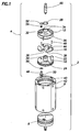
- a high-temperature, high-pressure filter press or other sealed apparatus 2 may have a cap 4 and a bottom assembly 6 for closing a cell 8.
- the cap 4 may include a base 10, a top 12, a connector 14 (illustrated in Figures 4A, 4B , 5A, and 5B ) between the base 10 and the top 12, one or more wings 16 between the base 10 and the top 12, and a lock 18 (illustrated in Figures 5A and 5B ).
- the base 10 may include a substantially planar, substantially circular plate configured to seal the cell 8. Additional features may include a groove configured to engage other components, such as o-rings or other elements used to provide a seal between the base 10 and the cell 8.
- the base 10 is configured to engage the top 12, such that relative movement between the base 10 and the top 12 causes the cap 4 to engage the cell 8.
- the base 10 may have an opening 20 shaped and sized to accommodate at least a portion of the lock 18. As illustrated, the opening 20 has a variable cross-section for different parts of the lock 18.
- the base 10 may have an indexing element 22 (e.g., pin) to provide alignment and/or leverage for moving the top 12 relative to the base.
- the top 12 engages the base 10 and is moveable relative to the base 10. This engagement may occur via a projecting portion 24 of the base 10.
- the projecting portion 24 may extend upward through a corresponding opening 26 in the top 12, and be secured by a retaining ring 28.
- the top 12 and the base 10 may be moveable relative to one another.
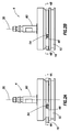
- the illustrated arrangement may allow for the relative movement between the base 10 and the top 12 to include rotational movement between the top 12 and the base 10, about an axis 30 (illustrated in Figures 2A to 5B ) passing through a center point of each of the top 12 and the base 10, while preventing separation of the top 12 and the base 10.
- the top 12 may have an opening 32 shaped and sized to accommodate at least a portion of the lock 18.
- the opening 32 is circular, however other shapes for the opening 32 may be selected for various designs of the apparatus 2.
- the top 12 may have one or more tool notches 34 to provide leverage for moving the top 12 relative to the base 10.
- the spring always moves the lock to the locked position when the cell wings are extended, regardless of pressure. The user must press the locking mechanism down to open the cell regardless of pressure. However pressing the button down depressurizes the cell as well as disengaging the lock. The spring always pushes the locking part up, even if no pressure is being exerted within the cell. However, when under pressure the lock assembly is very difficult to press down without first using valve (60) to vent the device which then allows with the button to be more easily depressed to unlock the cell. This provides added safety to ensure that pressure is vented when the wings are to be retracted to an open position.
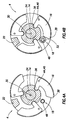
- FIGS. 4A and 4B illustrated are cross-sectional views of the cap 4 and the connector 14 taken along lines 4A-4A and lines 4B-4B in Figures 2A and 2B , respectively.
- the connector 14 may be generally arranged between the opposing axial surfaces of the base 10 and the top 12 and moveable relative to one or the other.
- the connector 14 forms an integral portion of the top 12 and may extend axially from the top 12 toward the base 10.
- the connector 14 may be coupled to the top 12 using mechanical fasteners, welding techniques, adhesives, combinations thereof, or the like. Consequently, the connector 14 as depicted is moveable relative to the base 10 during operation.
- the illustrated connector 14 may have a gear-shaped profile having a female configuration with at least three detents, notches, or grooves to engage a first portion 36 of a corresponding plurality of wings 16.
- Each wing 16 may define corresponding male profiles configured to interact with the female profiles of the connector 14.
- the connector 14 may be formed integrally with the base 10, may have any number of notches to engage any number of wings 16, and/or may have a male configuration corresponding to a female first portion 36 of wings 16.
- the connector 14 could be formed integrally with the base 10, such that the connector 14 is moveable relative to the top 12. In such embodiments, the disposition of the wings 16, as will be described below, may also have to be modified for proper operation. In yet other embodiments, the connector 14 may be formed separate from both the base 10 and the top 12, but may have a profile so as to prevent movement between the connector 14 and one of the base 10 and the top 12.
- One or more wings 16 may lie between the base 10 and the top 12. As illustrated, the cap 4 includes three wings 16. However, other numbers and configurations of wings may be used, depending on design considerations of various apparatus 2. For example, the cap 4 may include one, at least two, at least three, at least four, at least five, or more than five wings 16. Each wing 16 may have the first portion 36 engaging the connector 14, and a second portion 38 configured to engage the cell 8. The first portion 36 may engage the connector 14 via a cam-like male projection, as illustrated. Alternatively, the first portion 36 of the wing 16 may have another profile, such as a female first portion 36 configured to engage a corresponding female-shaped connector 14.
- the second portion 38 may engage the cell 8 by engaging a groove 40 formed in an inner wall 42 of the cell 8.
- the second portion 38 of the wing 16 may have a chamfered, slanted, or tapered shape and/or the groove 40 may have an angled cross-section.
- a face seal may be present.
- the second portion 38 of the wing 16 may have a curved shape to provide for a better load-bearing surface, or may have another suitable shape for the designed load.
- the wing 16 may include a point of rotation, or fulcrum 44 ( Figures 4A and 4B ) between the first portion 36 and the second portion 38.
- the fulcrum 44 may be substantially parallel to the axis 30 and may include a pin 46 or other connection allowing for the wing 16 to be attached to the cap 4, while allowing rotational movement of the wing 16.
- the pin 46 may pass through the wing 16 at the fulcrum 44 and may extend into the base 10 and/or the top 12.
- the pin 46 at the fulcrum 44 may allow for relative motion between the base 10 and the top 12 to provide movement of the second portion 38 of the wing 16 inward and outward, or toward and away from the axis 30.
- Relative rotational movement between the base 10 and the top 12 may cause the connector 14 to engage and move the first portion 36 of the wing 16, thereby causing the second portion 38 of the wing 16 to move.
- rotation of the base 10 about the axis 30 relative to the top 12 causes the connector 14 to rotate relative to the base 10.
- the connector 14 rotates, it causes the first portion 36 of the wing 16 to move.
- movement of the connector 14 caused by relative movement between the base 10 and the top 12 may cause the first portion 36 of the wing 16 to pivot about the fulcrum 44 in a first direction which, in turn, also causes the second portion 38 of the wing 16 to pivot about the fulcrum 44 in the first direction.
- the second portion 38 of the wing 16 may either be biased outward from the axis 30 or biased inward toward the axis 30.
- rotational movement in the first direction causes the wing 16 to engage the cell 8
- rotational movement in a second, opposite direction causes the wing 16 to disengage the cell 8.
- the wing 16 may be moved into and out of engagement with the cell 8 by relative rotation between the base 10 and the top 12.
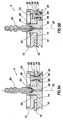
- the lock 18 may be configured to prevent relative movement between the base 10 and the top 12 when pressure within the cell 8 exceeds pressure outside the cell 8.
- the lock 18 may be further configured to allow relative movement between the base 10 and the top 12 when pressure within the cell 8 does not exceed pressure outside the cell 8.
- the lock 18 has a first, locked position when the pressure within the cell 8 exceeds pressure outside the cell 8 and a second, unlocked position when the pressure within the cell 8 does not exceed the pressure outside the cell 8.
- the lock 18 may include a bar 48, a plunger 50, and a button 52.
- the bar 48 may extend through the opening 20 in the base 10.
- the plunger 50 may lie at a base end of the bar 48, and the button 52 may lie at a top end of the bar 48.
- the plunger 50 may also extend at least partially into the opening 20 in the base 10.
- the lock 18 may include a spring 54 arranged between the button 52 and the base 10.
- the spring 54 may be configured to bias or otherwise maintain the lock 18 in a locked position.
- the lock 18 may include an o-ring 56 adapted to provide a seal between the plunger 50 and the base 10, and thereby preventing the passage of fluids through the opening 20 of the base 10 when the lock 18 is in the locked position.
- a port 58 may be defined in the base 10 to allow the passage of fluid(s) therethrough when the lock 18 is in the second, unlocked position.
- the port 58 may be arranged between the base 10 and at least a portion of the lock 18, such that depression of the button 52 allows fluid to pass from within the cell 8 to the environment.
- the port 58 In the first, locked position, the port 58 may be covered by the plunger 50 or other portion of the lock 18, thereby preventing the escape of fluid.
- depression of the button 52 may allow for a full release of pressure from the cell 8, or may allow for a partial release of pressure from the cell 8 (e.g., when pressure has been partially released prior to depression of the button 52).
- the lock 18 When pressure inside the cell 8 exceeds pressure outside the cell 8, the lock 18 may be moved to the unlocked position by exerting sufficient pressure on the button 52 to cause the pressure on the lock 18 to exceed the pressure inside the cell 8, including any bias from the optional spring 54. Pressure may then flow from within the cell 8 via the port 58, thereby causing equalization of pressure between the inside of the cell 8 and the outside of the cell 8.
- the cell 8 may be a cylindrical element, open at both ends, with the inner wall 42 having the groove 40 defined therein.
- the groove 40 may be configured to engage the wing(s) 16 and prevent movement of the cap 4, when the cap 4 is locked in position in the cell 8.
- the cell 8 may be a more conventional cell, with screw holes instead of a groove 40.
- Such a conventional cell may optionally be modified by adding a groove for more effective engagement with the cap 4.
- the bottom assembly 6 may include a cap similar to that described above, or may include other elements suitable for effectively sealing the apparatus 2 when combined with the cap 4 and the cell 8.
- the bottom assembly 6 and the cell 8 may be integrally formed as a single monolith structure, such that the cap 4 and the cell 8, which includes the bottom assembly 6, form an enclosed or sealed apparatus 2.
- a method for closing the cell 8 of the apparatus 2 may include providing the cap 4 as described above, placing at least a portion of the cap 4 into the cell 8, and moving the top 12 relative to the base 10, thereby causing the wing 16 to move or otherwise pivot until the wing 16 engages the cell 8.
- the wing 16 may engage the cell 8 at the groove 40 described above, or may otherwise move outward into contact with the inner wall 42 of the cell.
- Moving the top 12 relative to the base 10 may involve rotating the top 12 relative to the base 10 about the axis 30 passing through both the base 10 and the top 12, as described above.
- Moving the top 12 relative to the base 10 may cause the first portion 36 of the wing 16 to rotate or pivot about the fulcrum 44 in a first direction, which in turn, may cause the second portion 38 of the wing 16 to also rotate or pivot about the fulcrum 44.
- the method for closing the cell 8 may further include ensuring that the lock 18 is in a first, locked position. Ensuring that the lock 18 is in the locked position may involve inspecting the button 52 to determine that the button 52 is extended into the opening 32 in the top 12, and/or attempting to turn the top 12 relative to the base 10 to ensure that the lock 18 prevents such movement.
- the bottom assembly 6 may be attached to the cell 8, such that the bottom assembly 6, the cell 8, and the cap 4 form the apparatus 2.
- a method for opening the cell 8 of the apparatus 2 may include providing the cap 4, as described above, in engagement with the cell 8.
- the button 52 of the lock 18 may be depressed, thereby moving the lock 18 from the first, locked position, to the second, unlocked position. Depression of the button 52 may release pressure from within the cell 8. In other embodiments, however, pressure may be released from the cell 8 prior to depressing the button 52 by removing or manipulating a valve 60 that may be connected to or otherwise extending axially from the cap 4.
- a valve 60 may be connected to or otherwise extending axially from the cap 4.
- the top 12 may then be moved, relative to the base 10, thereby causing the wing 16 to move until disengaging from the cell 8.
- the cap 4 may then be removed from the cell 8.
- the movement of the top 12 relative to the base 10 may include rotating the top 12 relative to the base 10 about the axis 30 passing through both the base 10 and the top 12. Moving the top 12, relative to the base 10, may cause the first portion 36 of the wing 16 to rotate about the fulcrum 44 in a first direction, which in turn, causes the second portion 38 of the wing 16 to also rotate about the fulcrum 44.
- the method for opening the cell 8 may further include ensuring that the lock 18 is in the second, unlocked position prior to moving the top 12 relative to the base 10. Ensuring that the lock 18 is in the unlocked position may involve depressing the button 52 or inspecting the button 52 to determine that the button 52 is moved out of engagement with the opening 32 in the top 12, and/or attempting to turn the top 12 relative to the base 10 to ensure that the lock 18 permits such movement.
- Materials suitable for assembly 2, including cap 4 include metals, such as grade 304 or 316 stainless steel, or other materials suitable for use with a high-temperature, high-pressure filter press or other sealed apparatus.
Landscapes
- Engineering & Computer Science (AREA)
- General Engineering & Computer Science (AREA)
- Mechanical Engineering (AREA)
- Closures For Containers (AREA)
- Pressure Vessels And Lids Thereof (AREA)
- Connector Housings Or Holding Contact Members (AREA)
Claims (15)
- Deckel (4) für eine Zelle (8), umfassend:eine Basis (10);einen oberen Teil (12), der mit der Basis (10) in Eingriff steht und relativ zur Basis (10) beweglich ist;einen Verbinder (14), der zwischen der Basis (10) und dem oberen Teil (12) angeordnet und relativ zu nur einem von der Basis (10) und dem oberen Teil (12) beweglich ist;einen oder mehrere Flügel (16), die beweglich zwischen der Basis (10) und dem oberen Teil (12) angeordnet sind, wobei jeder Flügel (16) einen ersten Abschnitt (36), der mit dem Verbinder (14) in Eingriff steht, und einen zweiten Abschnitt (38) aufweist, der dazu ausgestaltet ist, mit der Zelle (8) in Eingriff zu treten; undeine Verriegelung (18);wobei, wenn Druck in der Zelle (8) Druck außerhalb der Zelle (8) übersteigt, die Verriegelung (18) in einer ersten Position liegt, die eine relative Bewegung zwischen der Basis (10) und dem oberen Teil (12) verhindert;
wobei, wenn Druck in der Zelle (8) Druck außerhalb der Zelle (8) nicht übersteigt, die Verriegelung (18) in einer zweiten Position liegt, die eine relative Bewegung zwischen der Basis (10) und dem oberen Teil (12) zulässt; und
wobei eine relative Bewegung zwischen der Basis (10) und dem oberen Teil (12) bewirkt, dass der Verbinder (14) den ersten Abschnitt (36) jedes Flügels (16) bewegt, wodurch bewirkt wird, dass sich der zweite Abschnitt (38) jedes Flügels (16) bewegt, dadurch gekennzeichnet, dass die Verriegelung (18) eine Stange (48), die sich durch eine Öffnung (32) erstreckt, die in der Basis (10) definiert ist, einen Kolben (50), der benachbart zu einem Basisende der Stange (48) angeordnet ist, und einen Knopf (52) umfasst, der benachbart zu einem oberen Ende der Stange (48) angeordnet ist;
wobei die erste Position der Verriegelung (18) eine Aufwärtsposition ist, wodurch sich der Knopf (52) in eine Öffnung (32) des oberen Teils (12) erstreckt; und
wobei die zweite Position der Verriegelung (18) eine Abwärtsposition ist, wobei sich der Knopf (52) nicht in die Öffnung (32) des oberen Teils (12) erstreckt und der eine oder die mehreren Flügel (16) sich von der Zelle (8) lösen können. - Deckel (4) nach Anspruch 1, wobei die relative Bewegung zwischen der Basis (10) und dem oberen Teil (12) eine Drehbewegung um eine Achse (30) umfasst, die sowohl durch die Basis als auch den oberen Teil verläuft, wobei vorzugsweise eine Drehbewegung des einen oder der mehreren Flügel (16) in einer ersten Richtung bewirkt, dass der eine oder die mehreren Flügel (16) mit der Zelle (8) in Eingriff treten und eine Drehbewegung in einer entgegengesetzten Richtung bewirkt, dass sich der eine oder die mehreren Flügel (16) von der Zelle (8) lösen.
- Deckel (4) nach Anspruch 1:wobei der eine oder die mehreren Flügel (16) einen Drehpunkt (44) zwischen dem ersten Abschnitt (36) und dem zweiten Abschnitt (38) umfassen; undwobei die relative Bewegung zwischen der Basis (10) und dem oberen Teil (12) bewirkt, dass sich der erste Abschnitt (36) des einen oder der mehreren Flügel (16) in einer ersten Richtung um den Drehpunkt (44) dreht, was wiederum bewirkt, dass sich auch der zweite Abschnitt (38) des Flügels (16) um den Drehpunkt (44) dreht, vorzugsweise ferner umfassend einen Stift (46), der am Drehpunkt (44) durch den einen oder die mehreren Flügel (16) verläuft, wobei der Stift (46) dazu ausgestaltet ist, sich in die Basis (10) und den oberen Teil (12) zu erstrecken.
- Deckel (4) nach Anspruch 1, wobei der eine oder die mehreren Flügel (16) wenigstens drei Flügel (16) umfassen.
- Deckel (4) nach Anspruch 1, umfassend eine Öffnung (58), die zwischen der Basis (10) und der Verriegelung (18) definiert ist, wobei die Öffnung (58) dazu ausgestaltet ist, Fluidverbindung bereitzustellen, wenn die Verriegelung in der zweiten Position ist.
- Deckel (4) nach Anspruch 1, wobei der Verbinder (14) einstückig mit dem oberen Teil (12) gebildet ist und sich axial davon erstreckt, derart, dass der Verbinder (14) nur relativ zur Basis (12) beweglich ist.
- Verfahren zum Schließen einer Zelle (8), umfassend:Bereitstellen eines Deckels (4), umfassend:wobei, wenn Druck in der Zelle (8) Druck außerhalb der Zelle (8) übersteigt, die Verriegelung (18) in einer ersten Position liegt, die eine relative Bewegung zwischen der Basis (10) und dem oberen Teil (12) verhindert;eine Basis (10);einen oberen Teil (12), der mit der Basis (10) in Eingriff steht und relativ zur Basis (10) beweglich ist;einen Verbinder (14), der zwischen der Basis (10) und dem oberen Teil (12) angeordnet und relativ zu nur einem von der Basis (10) und dem oberen Teil (12) beweglich ist;einen oder mehrere Flügel (16), die beweglich zwischen der Basis (10) und dem oberen Teil (12) angeordnet sind, wobei jeder Flügel (16) einen ersten Abschnitt (36), der mit dem Verbinder (14) in Eingriff steht, und einen zweiten Abschnitt (38) aufweist, der dazu ausgestaltet ist, mit der Zelle (8) in Eingriff zu treten; undeine Verriegelung (18);
wobei, wenn Druck in der Zelle (8) Druck außerhalb der Zelle (8) nicht übersteigt, die Verriegelung (18) in einer zweiten Position liegt, die eine relative Bewegung zwischen der Basis (10) und dem oberen Teil (12) zulässt; und
wobei eine relative Bewegung zwischen der Basis (10) und dem oberen Teil (12) bewirkt, dass der Verbinder (14) den ersten Abschnitt (36) des einen oder der mehreren Flügel (16) bewegt, wodurch bewirkt wird, dass sich der zweite Abschnitt (38) des einen oder der mehreren Flügel (16) bewegt;
Anordnen von wenigstens einem Abschnitt des Deckels (4) in der Zelle (8);
Bewegen des oberen Teils (12) relativ zur Basis (10) und dadurch Bewirken, dass sich der eine oder die mehreren Flügel (16) bewegen, bis der eine oder die mehreren Flügel (16) mit der Zelle (8) in Eingriff treten, dadurch gekennzeichnet, dass das Verfahren ferner das Gewährleisten umfasst, dass die Verriegelung (18) in der ersten Position ist;
wobei die Verriegelung (18) eine Stange (48), die sich durch eine Öffnung (32) erstreckt, die in der Basis (10) definiert ist, einen Kolben (50), der an einem Basisende der Stange (48) angeordnet ist, und einen Knopf (52) umfasst, der an einem oberen Ende der Stange (48) angeordnet ist;
wobei die erste Position der Verriegelung (18) eine Aufwärtsposition ist, wodurch sich der Knopf (52) in eine Öffnung (32) des oberen Teils (12) erstreckt; und
wobei die zweite Position der Verriegelung (18) eine Abwärtsposition ist, wodurch sich der Knopf (52) nicht in die Öffnung (32) des oberen Teils (12) erstreckt. - Verfahren nach Anspruch 7, wobei das Bewegen des oberen Teils (12) relativ zur Basis (10) das Drehen des oberen Teils (12) relativ zur Basis (10) um eine Achse (30) umfasst, die sowohl durch die Basis als auch durch den oberen Teil verläuft.
- Verfahren nach Anspruch 7:wobei der eine oder die mehreren Flügel (16) einen Drehpunkt (44) zwischen dem ersten Abschnitt (36) und dem zweiten Abschnitt (38) umfassen; undwobei das Bewegen des oberen Teils (12) relativ zur Basis (10) bewirkt, dass sich der erste Abschnitt (36) des Flügels (36) in einer ersten Richtung um den Drehpunkt (44) dreht, was wiederum bewirkt, dass sich auch der zweite Abschnitt (38) des Flügels (16) um den Drehpunkt (44) dreht.
- Verfahren zum Öffnen einer Zelle, umfassend:Bereitstellen eines Deckels (4) in Eingriff mit der Zelle (8), wobei der Deckel Folgendes umfasst:wobei, wenn Druck in der Zelle (8) Druck außerhalb der Zelle (8) übersteigt, die Verriegelung (18) in einer ersten Position liegt, die eine relative Bewegung zwischen der Basis (10) und dem oberen Teil (12) verhindert;eine Basis (10);einen oberen Teil (12), der mit der Basis (10) in Eingriff steht und relativ zur Basis (10) beweglich ist;einen Verbinder (14), der zwischen der Basis (10) und dem oberen Teil (12) angeordnet und relativ zu nur einem von der Basis und dem oberen Teil beweglich ist;einen oder mehrere Flügel (16), die beweglich zwischen der Basis (10) und dem oberen Teil (12) angeordnet sind, wobei jeder Flügel (16) einen ersten Abschnitt (36), der mit dem Verbinder (14) in Eingriff steht, und einen zweiten Abschnitt (38) aufweist, der dazu ausgestaltet ist, mit der Zelle (8) in Eingriff zu treten; undeine Verriegelung (18);
wobei, wenn Druck in der Zelle (8) Druck außerhalb der Zelle (8) nicht übersteigt, die Verriegelung (18) in einer zweiten Position liegt, die eine relative Bewegung zwischen der Basis (10) und dem oberen Teil (12) zulässt; und
wobei eine relative Bewegung zwischen der Basis (10) und dem oberen Teil (12) bewirkt, dass der Verbinder (14) den ersten Abschnitt (36) des einen oder der mehreren Flügel (16) bewegt, wodurch bewirkt wird, dass sich der zweite Abschnitt (38) des einen oder der mehreren Flügel (16) bewegt; dadurch gekennzeichnet, dass das Verfahren ferner Folgendes umfasst:
Niederdrücken eines Knopfes (52) der Verriegelung (18), wodurch die Verriegelung (18) aus der ersten Position in die zweite Position bewegt wird;
Bewegen des oberen Teils (12) relativ zur Basis (10), wodurch bewirkt wird, dass sich der Flügel (16) dreht, bis sich der eine oder die mehreren Flügel (16) von der Zelle (8) lösen; und
Entfernen des Deckels (4) von der Zelle (8). - Verfahren nach Anspruch 10, wobei das Bewegen des oberen Teils (12) relativ zur Basis (10) das Drehen des oberen Teils (12) relativ zur Basis (10) um eine Achse (30) umfasst, die sowohl durch die Basis (10) als auch durch den oberen Teil (12) verläuft.
- Verfahren nach Anspruch 10:wobei der eine oder die mehreren Flügel (16) einen Drehpunkt (44) zwischen dem ersten Abschnitt (36) und dem zweiten Abschnitt (38) umfassen; undwobei das Bewegen des oberen Teils (12) relativ zur Basis (10) umfasst, dass sich der erste Abschnitt (36) des einen oder der mehreren Flügel (16) in einer ersten Richtung um den Drehpunkt (44) dreht, was wiederum bewirkt, dass sich auch der zweite Abschnitt (38) des Flügels (16) um den Drehpunkt (44) dreht.
- Verfahren nach Anspruch 10, ferner umfassend Gewährleisten, dass die Verriegelung (18) in der zweiten Position ist, bevor der obere Teil (12) relativ zur Basis (10) bewegt wird;
wobei die Verriegelung (18) eine Stange (48), die sich durch eine Öffnung (32) erstreckt, die in der Basis (10) definiert ist, einen Kolben (50), der an einem Basisende der Stange (48) angeordnet ist, und einen Knopf (52) umfasst, der an einem oberen Ende der Stange (48) angeordnet ist;
wobei die erste Position der Verriegelung (18) eine Aufwärtsposition ist, wodurch sich der Knopf (52) in eine Öffnung (32) des oberen Teils (12) erstreckt; und
wobei die zweite Position der Verriegelung (18) eine Abwärtsposition ist, wodurch sich der Knopf (52) nicht in die Öffnung (32) des oberen Teils (12) erstreckt. - Verfahren nach Anspruch 10, ferner umfassend Ablassen von Druck aus der Zelle (8) vor dem Niederdrücken des Knopfes (52).
- Verfahren nach Anspruch 14, wobei das Niederdrücken des Knopfes (52) bewirkt, dass weiterer Druck aus der Zelle (8) entweicht.
Applications Claiming Priority (2)
| Application Number | Priority Date | Filing Date | Title |
|---|---|---|---|
| US13/358,693 US9091347B2 (en) | 2012-01-26 | 2012-01-26 | Safety cap |
| PCT/US2013/021365 WO2013112306A2 (en) | 2012-01-26 | 2013-01-14 | Safety cap |
Publications (2)
| Publication Number | Publication Date |
|---|---|
| EP2807408A2 EP2807408A2 (de) | 2014-12-03 |
| EP2807408B1 true EP2807408B1 (de) | 2016-10-19 |
Family
ID=47631730
Family Applications (1)
| Application Number | Title | Priority Date | Filing Date |
|---|---|---|---|
| EP13702294.3A Not-in-force EP2807408B1 (de) | 2012-01-26 | 2013-01-14 | Sicherheitskappe |
Country Status (8)
| Country | Link |
|---|---|
| US (1) | US9091347B2 (de) |
| EP (1) | EP2807408B1 (de) |
| AU (1) | AU2013212646B2 (de) |
| BR (1) | BR112014016402A8 (de) |
| CA (1) | CA2860387C (de) |
| EA (1) | EA201491075A1 (de) |
| MX (1) | MX349927B (de) |
| WO (1) | WO2013112306A2 (de) |
Families Citing this family (3)
| Publication number | Priority date | Publication date | Assignee | Title |
|---|---|---|---|---|
| WO2015041692A1 (en) * | 2013-09-23 | 2015-03-26 | Halliburton Energy Services, Inc. | Threaded safety cap |
| DE102014108787A1 (de) * | 2014-06-24 | 2015-12-24 | Amazonen-Werke H. Dreyer Gmbh & Co. Kg | Verschlussdeckel |
| US20170047532A1 (en) | 2015-08-13 | 2017-02-16 | Samsung Electronics Co., Ltd. | Organometallic compound, organic light-emitting device including the organometallic compound, and diagnosis composition including the organometallic compound |
Family Cites Families (11)
| Publication number | Priority date | Publication date | Assignee | Title |
|---|---|---|---|---|
| DE623561C (de) | ||||
| US3539212A (en) | 1968-06-26 | 1970-11-10 | Alexandr Pavlovich Poltorak | Lock for a quick opening cover of a pressure-resistant shell |
| FR2067501A5 (de) * | 1969-11-05 | 1971-08-20 | Bvs | |
| US4467936A (en) * | 1981-07-15 | 1984-08-28 | American Sterilizer Company | Closure for a pressurized chamber |
| DE3707601A1 (de) | 1986-10-24 | 1988-09-22 | Schwetzingen App & Filterbau | Sicherheitsverschluss bei druckrohren |
| US5148938A (en) * | 1987-03-04 | 1992-09-22 | Morgan Jr Howard W | Pressure vessel |
| FR2664348B1 (fr) * | 1990-07-09 | 1993-11-05 | Tecnoma | Recipient demontable, pouvant supporter une pression interne. |
| USD347799S (en) | 1993-02-24 | 1994-06-14 | Baroid Technology, Inc. | High pressure, high temperature test vessel with pressure warning indicator |
| US5520300A (en) | 1993-10-18 | 1996-05-28 | Stant Manufacturing Inc. | Lockable pressure relief fuel cap |
| US20070228043A1 (en) * | 2006-03-13 | 2007-10-04 | Dom Perruccio | Container top lock |
| US8091726B2 (en) | 2009-07-15 | 2012-01-10 | Halliburton Energy Services Inc. | Pressure vessels with safety closures and associated methods and systems |
-
2012
- 2012-01-26 US US13/358,693 patent/US9091347B2/en active Active
-
2013
- 2013-01-14 BR BR112014016402A patent/BR112014016402A8/pt not_active IP Right Cessation
- 2013-01-14 CA CA2860387A patent/CA2860387C/en not_active Expired - Fee Related
- 2013-01-14 EA EA201491075A patent/EA201491075A1/ru unknown
- 2013-01-14 EP EP13702294.3A patent/EP2807408B1/de not_active Not-in-force
- 2013-01-14 AU AU2013212646A patent/AU2013212646B2/en not_active Ceased
- 2013-01-14 WO PCT/US2013/021365 patent/WO2013112306A2/en not_active Ceased
- 2013-01-14 MX MX2014008168A patent/MX349927B/es active IP Right Grant
Also Published As
| Publication number | Publication date |
|---|---|
| CA2860387A1 (en) | 2013-08-01 |
| EA201491075A1 (ru) | 2014-12-30 |
| BR112014016402A2 (pt) | 2017-06-13 |
| US9091347B2 (en) | 2015-07-28 |
| AU2013212646B2 (en) | 2016-04-21 |
| BR112014016402A8 (pt) | 2017-07-04 |
| MX2014008168A (es) | 2014-10-06 |
| EP2807408A2 (de) | 2014-12-03 |
| CA2860387C (en) | 2016-09-13 |
| WO2013112306A3 (en) | 2014-04-17 |
| AU2013212646A1 (en) | 2014-09-18 |
| US20130193142A1 (en) | 2013-08-01 |
| WO2013112306A2 (en) | 2013-08-01 |
| MX349927B (es) | 2017-08-21 |
Similar Documents
| Publication | Publication Date | Title |
|---|---|---|
| US5148938A (en) | Pressure vessel | |
| US6286553B1 (en) | Removable closure system | |
| EP2807408B1 (de) | Sicherheitskappe | |
| CN103449014B (zh) | 饮料容器的栓体 | |
| US8444111B2 (en) | Combined valve | |
| CA2797203C (en) | Machine-actuated and removable safety closure with anti-rotation and machine-released holder | |
| US20080172944A1 (en) | Interlock vessel for hyperbaric transfer system | |
| KR102260854B1 (ko) | 로크아웃 표지 장치 및 밸브 | |
| CN104981640A (zh) | 回转顶轴阀促动器 | |
| US3128009A (en) | Closure means for pressure vessels | |
| AU2012258298A1 (en) | Machine-actuated and removable safety closure with anti-rotation and machine-released holder | |
| US10480675B2 (en) | No-bolt security latching system | |
| US4465202A (en) | Fluid container with venting means | |
| EP2500066B1 (de) | Übungslanghantel | |
| US20110260444A1 (en) | Safety locking device for pipe connector | |
| KR102206652B1 (ko) | 밸브용 원터치 잠금장치 | |
| CN101166927A (zh) | 误动作防止手动阀 | |
| KR20180095231A (ko) | 심부처분공 하강용 처분용기 체결장치 | |
| JP3179182U (ja) | 圧力鍋 | |
| EP1596119B1 (de) | Anschlussstück | |
| EP2052162A1 (de) | Verriegelungskolbenanordnung | |
| EP0878423A1 (de) | Rohrpostbüchse | |
| US20190011070A1 (en) | Divisible valve connector | |
| JP4124813B2 (ja) | 誤動作防止手動弁 | |
| JP3119133U (ja) | 液化ガスタンク用弁構造 |
Legal Events
| Date | Code | Title | Description |
|---|---|---|---|
| PUAI | Public reference made under article 153(3) epc to a published international application that has entered the european phase |
Free format text: ORIGINAL CODE: 0009012 |
|
| 17P | Request for examination filed |
Effective date: 20140624 |
|
| AK | Designated contracting states |
Kind code of ref document: A2 Designated state(s): AL AT BE BG CH CY CZ DE DK EE ES FI FR GB GR HR HU IE IS IT LI LT LU LV MC MK MT NL NO PL PT RO RS SE SI SK SM TR |
|
| DAX | Request for extension of the european patent (deleted) | ||
| GRAP | Despatch of communication of intention to grant a patent |
Free format text: ORIGINAL CODE: EPIDOSNIGR1 |
|
| INTG | Intention to grant announced |
Effective date: 20160523 |
|
| GRAS | Grant fee paid |
Free format text: ORIGINAL CODE: EPIDOSNIGR3 |
|
| GRAA | (expected) grant |
Free format text: ORIGINAL CODE: 0009210 |
|
| AK | Designated contracting states |
Kind code of ref document: B1 Designated state(s): AL AT BE BG CH CY CZ DE DK EE ES FI FR GB GR HR HU IE IS IT LI LT LU LV MC MK MT NL NO PL PT RO RS SE SI SK SM TR |
|
| REG | Reference to a national code |
Ref country code: GB Ref legal event code: FG4D |
|
| REG | Reference to a national code |
Ref country code: CH Ref legal event code: EP |
|
| REG | Reference to a national code |
Ref country code: AT Ref legal event code: REF Ref document number: 838639 Country of ref document: AT Kind code of ref document: T Effective date: 20161115 |
|
| REG | Reference to a national code |
Ref country code: IE Ref legal event code: FG4D |
|
| REG | Reference to a national code |
Ref country code: DE Ref legal event code: R096 Ref document number: 602013012926 Country of ref document: DE |
|
| REG | Reference to a national code |
Ref country code: NL Ref legal event code: MP Effective date: 20161019 |
|
| REG | Reference to a national code |
Ref country code: LT Ref legal event code: MG4D |
|
| PG25 | Lapsed in a contracting state [announced via postgrant information from national office to epo] |
Ref country code: LV Free format text: LAPSE BECAUSE OF FAILURE TO SUBMIT A TRANSLATION OF THE DESCRIPTION OR TO PAY THE FEE WITHIN THE PRESCRIBED TIME-LIMIT Effective date: 20161019 |
|
| REG | Reference to a national code |
Ref country code: NO Ref legal event code: T2 Effective date: 20161019 |
|
| REG | Reference to a national code |
Ref country code: AT Ref legal event code: MK05 Ref document number: 838639 Country of ref document: AT Kind code of ref document: T Effective date: 20161019 |
|
| PG25 | Lapsed in a contracting state [announced via postgrant information from national office to epo] |
Ref country code: GR Free format text: LAPSE BECAUSE OF FAILURE TO SUBMIT A TRANSLATION OF THE DESCRIPTION OR TO PAY THE FEE WITHIN THE PRESCRIBED TIME-LIMIT Effective date: 20170120 Ref country code: LT Free format text: LAPSE BECAUSE OF FAILURE TO SUBMIT A TRANSLATION OF THE DESCRIPTION OR TO PAY THE FEE WITHIN THE PRESCRIBED TIME-LIMIT Effective date: 20161019 Ref country code: SE Free format text: LAPSE BECAUSE OF FAILURE TO SUBMIT A TRANSLATION OF THE DESCRIPTION OR TO PAY THE FEE WITHIN THE PRESCRIBED TIME-LIMIT Effective date: 20161019 |
|
| PG25 | Lapsed in a contracting state [announced via postgrant information from national office to epo] |
Ref country code: AT Free format text: LAPSE BECAUSE OF FAILURE TO SUBMIT A TRANSLATION OF THE DESCRIPTION OR TO PAY THE FEE WITHIN THE PRESCRIBED TIME-LIMIT Effective date: 20161019 Ref country code: IS Free format text: LAPSE BECAUSE OF FAILURE TO SUBMIT A TRANSLATION OF THE DESCRIPTION OR TO PAY THE FEE WITHIN THE PRESCRIBED TIME-LIMIT Effective date: 20170219 Ref country code: FI Free format text: LAPSE BECAUSE OF FAILURE TO SUBMIT A TRANSLATION OF THE DESCRIPTION OR TO PAY THE FEE WITHIN THE PRESCRIBED TIME-LIMIT Effective date: 20161019 Ref country code: PT Free format text: LAPSE BECAUSE OF FAILURE TO SUBMIT A TRANSLATION OF THE DESCRIPTION OR TO PAY THE FEE WITHIN THE PRESCRIBED TIME-LIMIT Effective date: 20170220 Ref country code: HR Free format text: LAPSE BECAUSE OF FAILURE TO SUBMIT A TRANSLATION OF THE DESCRIPTION OR TO PAY THE FEE WITHIN THE PRESCRIBED TIME-LIMIT Effective date: 20161019 Ref country code: BE Free format text: LAPSE BECAUSE OF FAILURE TO SUBMIT A TRANSLATION OF THE DESCRIPTION OR TO PAY THE FEE WITHIN THE PRESCRIBED TIME-LIMIT Effective date: 20161019 Ref country code: NL Free format text: LAPSE BECAUSE OF FAILURE TO SUBMIT A TRANSLATION OF THE DESCRIPTION OR TO PAY THE FEE WITHIN THE PRESCRIBED TIME-LIMIT Effective date: 20161019 Ref country code: RS Free format text: LAPSE BECAUSE OF FAILURE TO SUBMIT A TRANSLATION OF THE DESCRIPTION OR TO PAY THE FEE WITHIN THE PRESCRIBED TIME-LIMIT Effective date: 20161019 Ref country code: PL Free format text: LAPSE BECAUSE OF FAILURE TO SUBMIT A TRANSLATION OF THE DESCRIPTION OR TO PAY THE FEE WITHIN THE PRESCRIBED TIME-LIMIT Effective date: 20161019 Ref country code: ES Free format text: LAPSE BECAUSE OF FAILURE TO SUBMIT A TRANSLATION OF THE DESCRIPTION OR TO PAY THE FEE WITHIN THE PRESCRIBED TIME-LIMIT Effective date: 20161019 |
|
| REG | Reference to a national code |
Ref country code: DE Ref legal event code: R097 Ref document number: 602013012926 Country of ref document: DE |
|
| PG25 | Lapsed in a contracting state [announced via postgrant information from national office to epo] |
Ref country code: RO Free format text: LAPSE BECAUSE OF FAILURE TO SUBMIT A TRANSLATION OF THE DESCRIPTION OR TO PAY THE FEE WITHIN THE PRESCRIBED TIME-LIMIT Effective date: 20161019 Ref country code: SK Free format text: LAPSE BECAUSE OF FAILURE TO SUBMIT A TRANSLATION OF THE DESCRIPTION OR TO PAY THE FEE WITHIN THE PRESCRIBED TIME-LIMIT Effective date: 20161019 Ref country code: CZ Free format text: LAPSE BECAUSE OF FAILURE TO SUBMIT A TRANSLATION OF THE DESCRIPTION OR TO PAY THE FEE WITHIN THE PRESCRIBED TIME-LIMIT Effective date: 20161019 Ref country code: EE Free format text: LAPSE BECAUSE OF FAILURE TO SUBMIT A TRANSLATION OF THE DESCRIPTION OR TO PAY THE FEE WITHIN THE PRESCRIBED TIME-LIMIT Effective date: 20161019 Ref country code: DK Free format text: LAPSE BECAUSE OF FAILURE TO SUBMIT A TRANSLATION OF THE DESCRIPTION OR TO PAY THE FEE WITHIN THE PRESCRIBED TIME-LIMIT Effective date: 20161019 |
|
| REG | Reference to a national code |
Ref country code: DE Ref legal event code: R119 Ref document number: 602013012926 Country of ref document: DE |
|
| PLBE | No opposition filed within time limit |
Free format text: ORIGINAL CODE: 0009261 |
|
| STAA | Information on the status of an ep patent application or granted ep patent |
Free format text: STATUS: NO OPPOSITION FILED WITHIN TIME LIMIT |
|
| PG25 | Lapsed in a contracting state [announced via postgrant information from national office to epo] |
Ref country code: IT Free format text: LAPSE BECAUSE OF FAILURE TO SUBMIT A TRANSLATION OF THE DESCRIPTION OR TO PAY THE FEE WITHIN THE PRESCRIBED TIME-LIMIT Effective date: 20161019 Ref country code: SM Free format text: LAPSE BECAUSE OF FAILURE TO SUBMIT A TRANSLATION OF THE DESCRIPTION OR TO PAY THE FEE WITHIN THE PRESCRIBED TIME-LIMIT Effective date: 20161019 Ref country code: BG Free format text: LAPSE BECAUSE OF FAILURE TO SUBMIT A TRANSLATION OF THE DESCRIPTION OR TO PAY THE FEE WITHIN THE PRESCRIBED TIME-LIMIT Effective date: 20170119 |
|
| REG | Reference to a national code |
Ref country code: CH Ref legal event code: PL |
|
| 26N | No opposition filed |
Effective date: 20170720 |
|
| PG25 | Lapsed in a contracting state [announced via postgrant information from national office to epo] |
Ref country code: MC Free format text: LAPSE BECAUSE OF FAILURE TO SUBMIT A TRANSLATION OF THE DESCRIPTION OR TO PAY THE FEE WITHIN THE PRESCRIBED TIME-LIMIT Effective date: 20161019 |
|
| REG | Reference to a national code |
Ref country code: FR Ref legal event code: ST Effective date: 20170929 |
|
| PG25 | Lapsed in a contracting state [announced via postgrant information from national office to epo] |
Ref country code: LI Free format text: LAPSE BECAUSE OF NON-PAYMENT OF DUE FEES Effective date: 20170131 Ref country code: FR Free format text: LAPSE BECAUSE OF NON-PAYMENT OF DUE FEES Effective date: 20170131 Ref country code: CH Free format text: LAPSE BECAUSE OF NON-PAYMENT OF DUE FEES Effective date: 20170131 |
|
| REG | Reference to a national code |
Ref country code: IE Ref legal event code: MM4A |
|
| PG25 | Lapsed in a contracting state [announced via postgrant information from national office to epo] |
Ref country code: DE Free format text: LAPSE BECAUSE OF NON-PAYMENT OF DUE FEES Effective date: 20170801 Ref country code: SI Free format text: LAPSE BECAUSE OF FAILURE TO SUBMIT A TRANSLATION OF THE DESCRIPTION OR TO PAY THE FEE WITHIN THE PRESCRIBED TIME-LIMIT Effective date: 20161019 Ref country code: LU Free format text: LAPSE BECAUSE OF NON-PAYMENT OF DUE FEES Effective date: 20170114 |
|
| PG25 | Lapsed in a contracting state [announced via postgrant information from national office to epo] |
Ref country code: IE Free format text: LAPSE BECAUSE OF NON-PAYMENT OF DUE FEES Effective date: 20170114 |
|
| PG25 | Lapsed in a contracting state [announced via postgrant information from national office to epo] |
Ref country code: MT Free format text: LAPSE BECAUSE OF NON-PAYMENT OF DUE FEES Effective date: 20170114 |
|
| PGFP | Annual fee paid to national office [announced via postgrant information from national office to epo] |
Ref country code: NO Payment date: 20181227 Year of fee payment: 7 |
|
| PG25 | Lapsed in a contracting state [announced via postgrant information from national office to epo] |
Ref country code: HU Free format text: LAPSE BECAUSE OF FAILURE TO SUBMIT A TRANSLATION OF THE DESCRIPTION OR TO PAY THE FEE WITHIN THE PRESCRIBED TIME-LIMIT; INVALID AB INITIO Effective date: 20130114 |
|
| PG25 | Lapsed in a contracting state [announced via postgrant information from national office to epo] |
Ref country code: CY Free format text: LAPSE BECAUSE OF FAILURE TO SUBMIT A TRANSLATION OF THE DESCRIPTION OR TO PAY THE FEE WITHIN THE PRESCRIBED TIME-LIMIT Effective date: 20161019 |
|
| PG25 | Lapsed in a contracting state [announced via postgrant information from national office to epo] |
Ref country code: MK Free format text: LAPSE BECAUSE OF FAILURE TO SUBMIT A TRANSLATION OF THE DESCRIPTION OR TO PAY THE FEE WITHIN THE PRESCRIBED TIME-LIMIT Effective date: 20161019 |
|
| PG25 | Lapsed in a contracting state [announced via postgrant information from national office to epo] |
Ref country code: TR Free format text: LAPSE BECAUSE OF FAILURE TO SUBMIT A TRANSLATION OF THE DESCRIPTION OR TO PAY THE FEE WITHIN THE PRESCRIBED TIME-LIMIT Effective date: 20161019 |
|
| PGFP | Annual fee paid to national office [announced via postgrant information from national office to epo] |
Ref country code: GB Payment date: 20191120 Year of fee payment: 8 |
|
| PG25 | Lapsed in a contracting state [announced via postgrant information from national office to epo] |
Ref country code: AL Free format text: LAPSE BECAUSE OF FAILURE TO SUBMIT A TRANSLATION OF THE DESCRIPTION OR TO PAY THE FEE WITHIN THE PRESCRIBED TIME-LIMIT Effective date: 20161019 |
|
| REG | Reference to a national code |
Ref country code: NO Ref legal event code: MMEP |
|
| PG25 | Lapsed in a contracting state [announced via postgrant information from national office to epo] |
Ref country code: NO Free format text: LAPSE BECAUSE OF NON-PAYMENT OF DUE FEES Effective date: 20200131 |
|
| GBPC | Gb: european patent ceased through non-payment of renewal fee |
Effective date: 20210114 |
|
| PG25 | Lapsed in a contracting state [announced via postgrant information from national office to epo] |
Ref country code: GB Free format text: LAPSE BECAUSE OF NON-PAYMENT OF DUE FEES Effective date: 20210114 |