EP2807359B1 - Commande adaptative de groupe motopropulseur de véhicule automobile - Google Patents
Commande adaptative de groupe motopropulseur de véhicule automobile Download PDFInfo
- Publication number
- EP2807359B1 EP2807359B1 EP13707559.4A EP13707559A EP2807359B1 EP 2807359 B1 EP2807359 B1 EP 2807359B1 EP 13707559 A EP13707559 A EP 13707559A EP 2807359 B1 EP2807359 B1 EP 2807359B1
- Authority
- EP
- European Patent Office
- Prior art keywords
- blending
- torque
- vehicle
- accelerator pedal
- rate
- Prior art date
- Legal status (The legal status is an assumption and is not a legal conclusion. Google has not performed a legal analysis and makes no representation as to the accuracy of the status listed.)
- Active
Links
Images


Classifications
-
- F—MECHANICAL ENGINEERING; LIGHTING; HEATING; WEAPONS; BLASTING
- F02—COMBUSTION ENGINES; HOT-GAS OR COMBUSTION-PRODUCT ENGINE PLANTS
- F02D—CONTROLLING COMBUSTION ENGINES
- F02D41/00—Electrical control of supply of combustible mixture or its constituents
- F02D41/24—Electrical control of supply of combustible mixture or its constituents characterised by the use of digital means
- F02D41/2406—Electrical control of supply of combustible mixture or its constituents characterised by the use of digital means using essentially read only memories
- F02D41/2409—Addressing techniques specially adapted therefor
- F02D41/2422—Selective use of one or more tables
-
- B—PERFORMING OPERATIONS; TRANSPORTING
- B60—VEHICLES IN GENERAL
- B60K—ARRANGEMENT OR MOUNTING OF PROPULSION UNITS OR OF TRANSMISSIONS IN VEHICLES; ARRANGEMENT OR MOUNTING OF PLURAL DIVERSE PRIME-MOVERS IN VEHICLES; AUXILIARY DRIVES FOR VEHICLES; INSTRUMENTATION OR DASHBOARDS FOR VEHICLES; ARRANGEMENTS IN CONNECTION WITH COOLING, AIR INTAKE, GAS EXHAUST OR FUEL SUPPLY OF PROPULSION UNITS IN VEHICLES
- B60K26/00—Arrangement or mounting of propulsion-unit control devices in vehicles
- B60K26/02—Arrangement or mounting of propulsion-unit control devices in vehicles of initiating means or elements
-
- B—PERFORMING OPERATIONS; TRANSPORTING
- B60—VEHICLES IN GENERAL
- B60K—ARRANGEMENT OR MOUNTING OF PROPULSION UNITS OR OF TRANSMISSIONS IN VEHICLES; ARRANGEMENT OR MOUNTING OF PLURAL DIVERSE PRIME-MOVERS IN VEHICLES; AUXILIARY DRIVES FOR VEHICLES; INSTRUMENTATION OR DASHBOARDS FOR VEHICLES; ARRANGEMENTS IN CONNECTION WITH COOLING, AIR INTAKE, GAS EXHAUST OR FUEL SUPPLY OF PROPULSION UNITS IN VEHICLES
- B60K26/00—Arrangement or mounting of propulsion-unit control devices in vehicles
- B60K26/04—Arrangement or mounting of propulsion-unit control devices in vehicles of means connecting initiating means or elements to propulsion unit
-
- B—PERFORMING OPERATIONS; TRANSPORTING
- B60—VEHICLES IN GENERAL
- B60W—CONJOINT CONTROL OF VEHICLE SUB-UNITS OF DIFFERENT TYPE OR DIFFERENT FUNCTION; CONTROL SYSTEMS SPECIALLY ADAPTED FOR HYBRID VEHICLES; ROAD VEHICLE DRIVE CONTROL SYSTEMS FOR PURPOSES NOT RELATED TO THE CONTROL OF A PARTICULAR SUB-UNIT
- B60W10/00—Conjoint control of vehicle sub-units of different type or different function
- B60W10/04—Conjoint control of vehicle sub-units of different type or different function including control of propulsion units
-
- B—PERFORMING OPERATIONS; TRANSPORTING
- B60—VEHICLES IN GENERAL
- B60W—CONJOINT CONTROL OF VEHICLE SUB-UNITS OF DIFFERENT TYPE OR DIFFERENT FUNCTION; CONTROL SYSTEMS SPECIALLY ADAPTED FOR HYBRID VEHICLES; ROAD VEHICLE DRIVE CONTROL SYSTEMS FOR PURPOSES NOT RELATED TO THE CONTROL OF A PARTICULAR SUB-UNIT
- B60W10/00—Conjoint control of vehicle sub-units of different type or different function
- B60W10/04—Conjoint control of vehicle sub-units of different type or different function including control of propulsion units
- B60W10/06—Conjoint control of vehicle sub-units of different type or different function including control of propulsion units including control of combustion engines
-
- B—PERFORMING OPERATIONS; TRANSPORTING
- B60—VEHICLES IN GENERAL
- B60W—CONJOINT CONTROL OF VEHICLE SUB-UNITS OF DIFFERENT TYPE OR DIFFERENT FUNCTION; CONTROL SYSTEMS SPECIALLY ADAPTED FOR HYBRID VEHICLES; ROAD VEHICLE DRIVE CONTROL SYSTEMS FOR PURPOSES NOT RELATED TO THE CONTROL OF A PARTICULAR SUB-UNIT
- B60W30/00—Purposes of road vehicle drive control systems not related to the control of a particular sub-unit, e.g. of systems using conjoint control of vehicle sub-units
- B60W30/18—Propelling the vehicle
- B60W30/188—Controlling power parameters of the driveline, e.g. determining the required power
-
- B—PERFORMING OPERATIONS; TRANSPORTING
- B60—VEHICLES IN GENERAL
- B60W—CONJOINT CONTROL OF VEHICLE SUB-UNITS OF DIFFERENT TYPE OR DIFFERENT FUNCTION; CONTROL SYSTEMS SPECIALLY ADAPTED FOR HYBRID VEHICLES; ROAD VEHICLE DRIVE CONTROL SYSTEMS FOR PURPOSES NOT RELATED TO THE CONTROL OF A PARTICULAR SUB-UNIT
- B60W50/00—Details of control systems for road vehicle drive control not related to the control of a particular sub-unit, e.g. process diagnostic or vehicle driver interfaces
- B60W50/08—Interaction between the driver and the control system
- B60W50/082—Selecting or switching between different modes of propelling
-
- F—MECHANICAL ENGINEERING; LIGHTING; HEATING; WEAPONS; BLASTING
- F02—COMBUSTION ENGINES; HOT-GAS OR COMBUSTION-PRODUCT ENGINE PLANTS
- F02D—CONTROLLING COMBUSTION ENGINES
- F02D11/00—Arrangements for, or adaptations to, non-automatic engine control initiation means, e.g. operator initiated
- F02D11/06—Arrangements for, or adaptations to, non-automatic engine control initiation means, e.g. operator initiated characterised by non-mechanical control linkages, e.g. fluid control linkages or by control linkages with power drive or assistance
- F02D11/10—Arrangements for, or adaptations to, non-automatic engine control initiation means, e.g. operator initiated characterised by non-mechanical control linkages, e.g. fluid control linkages or by control linkages with power drive or assistance of the electric type
- F02D11/105—Arrangements for, or adaptations to, non-automatic engine control initiation means, e.g. operator initiated characterised by non-mechanical control linkages, e.g. fluid control linkages or by control linkages with power drive or assistance of the electric type characterised by the function converting demand to actuation, e.g. a map indicating relations between an accelerator pedal position and throttle valve opening or target engine torque
-
- F—MECHANICAL ENGINEERING; LIGHTING; HEATING; WEAPONS; BLASTING
- F02—COMBUSTION ENGINES; HOT-GAS OR COMBUSTION-PRODUCT ENGINE PLANTS
- F02D—CONTROLLING COMBUSTION ENGINES
- F02D41/00—Electrical control of supply of combustible mixture or its constituents
- F02D41/02—Circuit arrangements for generating control signals
- F02D41/14—Introducing closed-loop corrections
- F02D41/1401—Introducing closed-loop corrections characterised by the control or regulation method
-
- B—PERFORMING OPERATIONS; TRANSPORTING
- B60—VEHICLES IN GENERAL
- B60K—ARRANGEMENT OR MOUNTING OF PROPULSION UNITS OR OF TRANSMISSIONS IN VEHICLES; ARRANGEMENT OR MOUNTING OF PLURAL DIVERSE PRIME-MOVERS IN VEHICLES; AUXILIARY DRIVES FOR VEHICLES; INSTRUMENTATION OR DASHBOARDS FOR VEHICLES; ARRANGEMENTS IN CONNECTION WITH COOLING, AIR INTAKE, GAS EXHAUST OR FUEL SUPPLY OF PROPULSION UNITS IN VEHICLES
- B60K26/00—Arrangement or mounting of propulsion-unit control devices in vehicles
- B60K26/04—Arrangement or mounting of propulsion-unit control devices in vehicles of means connecting initiating means or elements to propulsion unit
- B60K2026/046—Arrangement or mounting of propulsion-unit control devices in vehicles of means connecting initiating means or elements to propulsion unit with electrical transmission means
-
- B—PERFORMING OPERATIONS; TRANSPORTING
- B60—VEHICLES IN GENERAL
- B60W—CONJOINT CONTROL OF VEHICLE SUB-UNITS OF DIFFERENT TYPE OR DIFFERENT FUNCTION; CONTROL SYSTEMS SPECIALLY ADAPTED FOR HYBRID VEHICLES; ROAD VEHICLE DRIVE CONTROL SYSTEMS FOR PURPOSES NOT RELATED TO THE CONTROL OF A PARTICULAR SUB-UNIT
- B60W50/00—Details of control systems for road vehicle drive control not related to the control of a particular sub-unit, e.g. process diagnostic or vehicle driver interfaces
- B60W2050/0062—Adapting control system settings
- B60W2050/0075—Automatic parameter input, automatic initialising or calibrating means
- B60W2050/0095—Automatic control mode change
- B60W2050/0096—Control during transition between modes
-
- B—PERFORMING OPERATIONS; TRANSPORTING
- B60—VEHICLES IN GENERAL
- B60W—CONJOINT CONTROL OF VEHICLE SUB-UNITS OF DIFFERENT TYPE OR DIFFERENT FUNCTION; CONTROL SYSTEMS SPECIALLY ADAPTED FOR HYBRID VEHICLES; ROAD VEHICLE DRIVE CONTROL SYSTEMS FOR PURPOSES NOT RELATED TO THE CONTROL OF A PARTICULAR SUB-UNIT
- B60W2510/00—Input parameters relating to a particular sub-units
- B60W2510/06—Combustion engines, Gas turbines
- B60W2510/0657—Engine torque
- B60W2510/0661—Torque change rate
-
- B—PERFORMING OPERATIONS; TRANSPORTING
- B60—VEHICLES IN GENERAL
- B60W—CONJOINT CONTROL OF VEHICLE SUB-UNITS OF DIFFERENT TYPE OR DIFFERENT FUNCTION; CONTROL SYSTEMS SPECIALLY ADAPTED FOR HYBRID VEHICLES; ROAD VEHICLE DRIVE CONTROL SYSTEMS FOR PURPOSES NOT RELATED TO THE CONTROL OF A PARTICULAR SUB-UNIT
- B60W2540/00—Input parameters relating to occupants
- B60W2540/10—Accelerator pedal position
-
- B—PERFORMING OPERATIONS; TRANSPORTING
- B60—VEHICLES IN GENERAL
- B60W—CONJOINT CONTROL OF VEHICLE SUB-UNITS OF DIFFERENT TYPE OR DIFFERENT FUNCTION; CONTROL SYSTEMS SPECIALLY ADAPTED FOR HYBRID VEHICLES; ROAD VEHICLE DRIVE CONTROL SYSTEMS FOR PURPOSES NOT RELATED TO THE CONTROL OF A PARTICULAR SUB-UNIT
- B60W2540/00—Input parameters relating to occupants
- B60W2540/10—Accelerator pedal position
- B60W2540/103—Accelerator thresholds, e.g. kickdown
-
- B—PERFORMING OPERATIONS; TRANSPORTING
- B60—VEHICLES IN GENERAL
- B60W—CONJOINT CONTROL OF VEHICLE SUB-UNITS OF DIFFERENT TYPE OR DIFFERENT FUNCTION; CONTROL SYSTEMS SPECIALLY ADAPTED FOR HYBRID VEHICLES; ROAD VEHICLE DRIVE CONTROL SYSTEMS FOR PURPOSES NOT RELATED TO THE CONTROL OF A PARTICULAR SUB-UNIT
- B60W2540/00—Input parameters relating to occupants
- B60W2540/10—Accelerator pedal position
- B60W2540/106—Rate of change
-
- B—PERFORMING OPERATIONS; TRANSPORTING
- B60—VEHICLES IN GENERAL
- B60W—CONJOINT CONTROL OF VEHICLE SUB-UNITS OF DIFFERENT TYPE OR DIFFERENT FUNCTION; CONTROL SYSTEMS SPECIALLY ADAPTED FOR HYBRID VEHICLES; ROAD VEHICLE DRIVE CONTROL SYSTEMS FOR PURPOSES NOT RELATED TO THE CONTROL OF A PARTICULAR SUB-UNIT
- B60W2540/00—Input parameters relating to occupants
- B60W2540/215—Selection or confirmation of options
-
- B—PERFORMING OPERATIONS; TRANSPORTING
- B60—VEHICLES IN GENERAL
- B60W—CONJOINT CONTROL OF VEHICLE SUB-UNITS OF DIFFERENT TYPE OR DIFFERENT FUNCTION; CONTROL SYSTEMS SPECIALLY ADAPTED FOR HYBRID VEHICLES; ROAD VEHICLE DRIVE CONTROL SYSTEMS FOR PURPOSES NOT RELATED TO THE CONTROL OF A PARTICULAR SUB-UNIT
- B60W2710/00—Output or target parameters relating to a particular sub-units
- B60W2710/10—Change speed gearings
- B60W2710/105—Output torque
-
- F—MECHANICAL ENGINEERING; LIGHTING; HEATING; WEAPONS; BLASTING
- F02—COMBUSTION ENGINES; HOT-GAS OR COMBUSTION-PRODUCT ENGINE PLANTS
- F02D—CONTROLLING COMBUSTION ENGINES
- F02D41/00—Electrical control of supply of combustible mixture or its constituents
- F02D41/02—Circuit arrangements for generating control signals
- F02D41/14—Introducing closed-loop corrections
- F02D41/1401—Introducing closed-loop corrections characterised by the control or regulation method
- F02D2041/1413—Controller structures or design
- F02D2041/1432—Controller structures or design the system including a filter, e.g. a low pass or high pass filter
-
- F—MECHANICAL ENGINEERING; LIGHTING; HEATING; WEAPONS; BLASTING
- F02—COMBUSTION ENGINES; HOT-GAS OR COMBUSTION-PRODUCT ENGINE PLANTS
- F02D—CONTROLLING COMBUSTION ENGINES
- F02D2200/00—Input parameters for engine control
- F02D2200/70—Input parameters for engine control said parameters being related to the vehicle exterior
- F02D2200/702—Road conditions
-
- F—MECHANICAL ENGINEERING; LIGHTING; HEATING; WEAPONS; BLASTING
- F02—COMBUSTION ENGINES; HOT-GAS OR COMBUSTION-PRODUCT ENGINE PLANTS
- F02D—CONTROLLING COMBUSTION ENGINES
- F02D2250/00—Engine control related to specific problems or objectives
- F02D2250/18—Control of the engine output torque
- F02D2250/21—Control of the engine output torque during a transition between engine operation modes or states
Definitions
- the present invention relates to a method according to the preamble of claims 1 and 2 and to a system according to the preamble of claim 11 and 12.
- Embodiments of the present invention relate to adaptive control of a powertrain of a motor vehicle.
- embodiments of the present invention relate to adaptive control of a source of motive power, for example an internal combustion engine and in particular, but not exclusively, to the response of the engine to an operator command in consequence of a change of engine operating mode.
- the change of engine operating mode may in turn be related to a change of operating mode of a vehicle in which the engine is installed.
- aspects of the invention relate to a method, to a system and to a vehicle.
- Internal combustion engines of vehicles may have operating modes which may be selectable by the driver.
- an economy mode a normal mode and a sport mode may be provided, each mode having a different engine response to one or more commands of the driver.
- the engine may respond differently in each mode to a given input of the accelerator pedal, being least responsive in economy mode, and most responsive in sport mode.
- driveability of the vehicle can be improved by providing a range of accelerator pedal movement which is appropriate to, for example, the output torque characteristic of the engine.
- Such a system necessarily relies upon an electronic input from the vehicle driver, for example an accelerator potentiometer providing an input signal to an electronic control unit having a plurality of accelerator pedal position/output torque maps.
- the maps may also be referred to as or accelerator pedal progression maps.
- WO 03/076834 A1 discloses a method and a system according to the preamble of claims 1 and 11.
- US patent US 7,349,776 describes a vehicle control system in which the driver can implement improved control over a broad range of driving conditions, and in particular over a number of different terrains which may be encountered when driving off-road.
- the vehicle control system is selected to operate in one of a number of different driving modes including one or more terrain response (TR) modes.
- TR terrain response
- the various vehicle subsystems are operated in a manner appropriate to the corresponding terrain.
- a mode for example a winter mode
- the vehicle is configured to launch from standstill in a forward gear other than first gear such as a second gear to reduce risk of excessive wheel slip.
- Different modes may have different accelerator pedal position/output torque maps, torque delivery (accelerator pedal position/output torque maps in combination with a rate at which engagement of transmission clutches is controlled to take place thereby determining how aggressively gear shifts take place), and transmission shift points as a function of coefficient of surface friction.
- the transmission shift points may be arranged wherein gear shifts take place at lower speeds than they might otherwise take place at, and in a more gentle manner (e.g. at a slower rate).
- a vehicle control unit selects a corresponding one or more accelerator/torque maps. For example when driving in rocky terrain, a mode appropriate to travel over such terrain may be selected in which the accelerator pedal/output torque map generates a high torque output for a small accelerator movement, thus giving immediate urge to overcome a rock step. In contrast on sand, a low torque output may be indicated for the same accelerator movement, so as to avoid spinning the vehicle wheels and digging a hole. To some extent the selected terrain response mode (and therefore torque map) may be a matter of judgement by a user related for example to the available grip of one or more wheels of the vehicle on the terrain.
- Any two torque maps associated with different respective vehicle operating modes coincide at zero accelerator position/zero torque and maximum accelerator position/maximum torque. In between these conditions, if the map being used to determine engine output torque as a function of accelerator pedal position changes, an immediate change of engine output torque may occur.
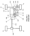
- FIG. 1 shows a known motor vehicle 101 having a powertrain 101 P.
- the powertrain 101 P includes an engine 121, a transmission 124, a power take-off unit (PTU) 137, a rear driveshaft or propshaft 131 R and a front driveshaft or propshaft 131 F.
- the rear driveshaft 131 R is operable to drive a pair of rear wheels 113, 114 via a rear differential 135R whilst the front driveshaft 131F is operable to drive a pair of front wheels 111, 112 via a front differential 135F.
- the vehicle 101 has an engine controller 121C arranged to receive an accelerator pedal position signal from an accelerator pedal 161 and a brakes controller 141C operable to receive a brake pedal position signal from a brake pedal 163.
- the transmission 124 is releasably connectable to the rear driveshaft 131R by means of the power transfer unit (PTU) 137, allowing selectable two wheel drive or four wheel drive operation.
- PTU power transfer unit
- the PTU 137 is also operable in a 'high ratio' or a 'low ratio' configuration, in which a gear ratio between an input shaft and an output shaft thereof is selected to be a high or low ratio.
- the high ratio configuration is suitable for general on-road or 'on-highway' operations whilst the low ratio configuration is more suitable for negotiating certain off-road terrain conditions and other low speed applications such as towing.
- the vehicle 101 has a central controller 101C, referred to as a vehicle control unit (VCU) 101C.
- VCU vehicle control unit
- the VCU 101C receives and outputs a plurality of signals to and from various sensors and subsystems provided on the vehicle 101.
- the vehicle 101 has a transmission mode selector dial 124S operable to select a required operating mode of the transmission 124.
- the selector dial 124S provides a control signal to a transmission controller 124C which in turn controls the transmission 124 to operate according to the selected mode.
- Available modes include a park mode, a reverse mode and a drive mode.
- the vehicle 101 also has a terrain response mode selector dial 128S.
- the terrain response mode selector dial 128S is operable by a driver to select a required terrain response mode of operation of the vehicle.
- the engine controller 121C employs a drive mode throttle map to determine the amount of drive torque that the engine 121 should produce as a function of accelerator pedal position. If the user selects the sport mode of the transmission, the engine controller 121C employs a sport mode throttle map instead of the drive mode throttle map.
- the throttle maps differ in that the sport mode throttle map is arranged to provide a more aggressive response by the engine 121C to a given initial advance (such as depression) of the accelerator pedal 161. Different respective driveability filters may also be applied in dependence on the selected transmission mode.
- the vehicle may be operable automatically to select an appropriate TR mode for the prevailing driving conditions.
- FIG. 2 shows two different accelerator pedal progression maps in the form of a plot of engine torque output T as a function of accelerator pedal position P on a scale from 0 to 100% of full scale depression of the accelerator pedal 161.
- FIG. 2 shows two extreme vehicle operating modes A,B.
- Mode A is a cautious torque map and may correspond for example to a TR mode suitable for use when driving over sand.
- Mode B is a more aggressive torque map and may correspond to a TR mode suitable for use when driving over rock.
- a driver may select operation according to mode A or mode B by means of the TR mode selector dial 128S.
- the torque maps coincide, but at part depression of the accelerator pedal 161 significant differences in torque output are apparent.
- the change in output torque of the engine may take time, and can be deliberately blended, as illustrated in FIG. 3.
- FIG. 3 is a plot of output torque as a function of time during blending from mode A to mode B at point C.
- the increase from point C to point D may be controlled to avoid a step change.
- a maximum blending rate say 7 Nm/s may be applied, and/or blending may take place at a defined rate within a maximum time period, of say 20 seconds.
- a small torque change will blend quickly, and a large torque change will take longer.
- the vehicle driver may wish to move the accelerator pedal 161 to demand more or less torque from the vehicle engine 121. It would be desirable to minimize the changeover time commensurate with the changing demands of the vehicle driver.
- a method of blending between different characteristics of accelerator pedal position and output torque in a vehicle comprising the steps of:
- a method of blending between different characteristics of accelerator position and output torque in a vehicle comprising the steps of:
- the characteristic relating accelerator pedal position to output torque may directly indicate the torque output at the flywheel of an internal combustion engine, or may represent an analogue thereof, such as one or more of drive torque at the vehicle wheels, power output, another measure of tractive effort, fuel flow, air flow or any measurable indicator that varies accordingly to accelerator pedal progression and torque output.
- the output torque may represent the output of other forms of motive power, such as an electric motor, or an analogue thereof, such as motor current.
- output torque may correspond to a net torque delivered to a powertrain by an engine and one or more electric propulsion motors.
- a change in torque demand, due to a change of vehicle operating mode, to a target characteristic will be completed comparatively quickly if during the transition the vehicle driver re-positions the accelerator pedal in the direction of the changing torque demand.
- Embodiments of the invention reflect that a vehicle driver will be less disconcerted by a changing torque output due to mode change, if the intention of the driver is in the direction of changing torque output.
- the base blending rate may be zero or positive, and the increased rate will be a greater value.
- the base blending rate will be positive, and the reduced rate will be a lesser rate, or zero.
- Embodiments of the present invention can be implemented in several ways.
- a base blending rate is applied when a change in output torque due to a mode change is required, and driver torque demand changes in the direction of the change of torque.
- a reduced blending rate is applied for a substantially unchanging driver demand and for changes in driver torque demand that occur in the opposite direction to the blend.
- a base blending rate is applied when a change in output torque due to a mode change takes place accompanied by substantially unchanging driver demand or by a driver demand opposite to the direction of the change in torque.
- An increased blending rate is applied for driver demand in the direction of the change.
- a standard blending rate may be determined, and increased and/or reduced rates of blending applied according to the direction of driver demand in relation to the change of output torque due to mode change.
- a fixed base blending rate may be applied for all pedal progression (torque) characteristics, but preferably the base blending rate is selected according to the particular source and target maps.
- the base blending rate may be varied according to the difference between the source and target torque at the instant pedal position, a greater rate being applied where the difference is greater.
- the base blending rate may be varied according to the position of the accelerator pedal, so that different rates may apply as the pedal moves from fully closed to fully open. These different rates may for example be retained in a look-up table by reference to torque map and accelerator pedal position.
- the changed blending rate may be discrete or defined as a percentage of the base blending rate, or be changed according to the difference between the torque maps, or according to the instant position of the accelerator pedal. It is to be understood that reference to percentage is directly equivalent to reference to a proportion, in contrast with a fixed absolute value that is not a proportion of another value.
- the change in blending rate due to a particular condition and instant position of the accelerator pedal is linked to the instant torque difference between the source and target torque characteristics.
- an increased rate of blend consequent upon driver demand in the direction of the blend may be a step change, for example a rate increase in the range 30-100%, during the period of increased rate.
- the rate increase is proportional to the instant torque difference so that a high rate is applied for a large torque difference, and this rate is gradually reduced as the torque difference reduces.
- the rate may vary according to the instant position of the accelerator pedal.
- an electronic control system of a vehicle for blending between different characteristics of accelerator pedal position and output torque by reference to a plurality of torque maps held within a memory, said system being adapted to detect a first operating mode of the vehicle and apply a source torque map, detect a change of operating mode of the vehicle and select a target torque map, and blend the torque map applied from said source torque map to said target torque map at a base blending rate, said base blending rate being increased if the torque change due to blending is in the direction of driver demand.
- the blending rate may be reduced if during blending the position of the accelerator pedal is not substantially moved, or is moved oppositely to the direction of torque change due to blending.
- an aspect of the invention provides a vehicle having such an electronic control system and a system of automatically changing operating mode in response to different conditions of use, such as a change of terrain.
- FIG. 4 is a schematic illustration of a motor vehicle 201 according to an embodiment of the present invention. Like features of the vehicle 201 of FIG. 4 to those of the vehicle 101 of FIG. 1 are shown with like reference numerals prefixed numeral 2 instead of numeral 1. Thus engine 121 of the vehicle 101 of FIG. 1 corresponds to engine 221 of the vehicle 201 of FIG. 4 .
- the vehicle 201 has a VCU 201 programmed with accelerator pedal progression maps that are used to determine engine torque T as a function of accelerator pedal position P.
- FIG. 5 is a plot of engine torque (T) against time(t) over a period of changing accelerator pedal position for the vehicle 201 of FIG. 4 .
- Two vehicle modes M1, M2 are illustrated, each mode having a different output torque from the engine 221 in response to a given accelerator pedal position.
- Mode M1 may be characterised as cautious, corresponding to program A of FIG. 1
- mode M2 corresponds to program B of FIG. 1 , and is more aggressive.
- Accelerator pedal position is not shown, but torque increases and decreases can be assumed to follow a similar change to accelerator pedal position.
- the accelerator pedal 161 is not advanced (and is therefore in a substantially released position, at a substantially undepressed or neutral position) and engine torque output may be considered to be substantially zero even if the engine 221 is running at idle speed.
- the VCU 201C automatically changes the mode of operation of the vehicle to mode M2, for example due to detection of a change of terrain by means not described here. Blending of engine output torque T to that required for operation in mode M2 commences at a fixed base rate determined empirically as the maximum rate which a vehicle driver will accept without becoming disconcerted during an automatic mode change.
- the instant torque (mode M1) is about 80 Nm
- the target torque (mode M2) is about 200 Nm.
- the difference is thus 120 Nm
- a typical base blending rate is 7 Nm/s although other values may be used instead. If accelerator position remains unchanged, blending from M1 to M2 at the base rate will thus take about 17 seconds, in this example.
- the accelerator pedal 161 is paused until t 6 , and further upward divergence at the base blending rate is apparent in this period.
- the accelerator pedal 161 is again advanced. Since driver demand for increased torque is in the direction of blending from M1 to M2, the rate of blending is increased above the base blending rate, so that by the time the accelerator pedal is again paused at t 7 , engine output torque T has rapidly approached M2.
- the period from t 3 to t 6 at the base blending rate provided for about 25% of blending to be completed.
- the shorter period from t 6 to t 7 at the increased blending rate allowed blending to reach about 60% completion.
- the accelerator pedal is again paused, and blending is resumed at the base blending rate. If no further change of accelerator position is made before blending is completed, the time for blending will have reduced from about 17 seconds to about 12 seconds.
- a change in vehicle mode at time t 8 to a more cautious engine torque map causes blending at the base rate from t 8 to t 9 - in this period the accelerator pedal position is not changing.
- the accelerator pedal 261 is backed-off, to demand a lower torque from the engine 221. Since this action is in the direction of mode change from M2 to M1, the base blending rate is increased, so that by t 10 when movement of the accelerator pedal 261 is paused, 50% of the blend is completed.
- blending continues at the base rate, and does so during a period of an advancing accelerator pedal position from t 11 to t 12 , and at a paused position after t 12 .
- Special measures may be employed when the accelerator pedal is moved rapidly towards the maximum and minimum positions.
- the VCU 201C is arranged to command substantially immediately the application of substantially the full amount of engine torque T corresponding to position U of FIG. 2 .
- blending is determined by the VCU 201C to be complete substantially immediately when the accelerator pedal 261 is advanced to the maximum position (corresponding to position U) or retreated to the minimum position (which may be defined as less than 5% of the full travel of the accelerator pedal 261 and corresponds to position L). No further blending is therefore required, and further accelerator pedal movement results in engine response according to the mode trace to which blending was being performed.
- the prescribed rates for advancement or backing of the pedal 261 may be substantially the same or different.
- definition and recognition of the minimum and maximum accelerator positions may be selected according to the nature and precision of the accelerator pedal mechanism, and in particular to the accuracy, noise and hysteresis present in the output of a potentiometer indicative of pedal position. Selection and adjustment of these parameters is within the ability of an appropriately skilled person.
- the rate of change of accelerator pedal position may be sensed in some embodiments in order to determine whether movement to the maximum and minimum positions is in progress, and thereby give an early indication that engine output torque should be maximized or minimized substantially immediately.
- a method of blending is implemented whereby the blending rate is increased when driver demand is in the direction of blend.
- the same effect may be realized in a method where blending rate is reduced, typically to zero, when driver demand is unchanging or opposite to the direction of blend.
- a base blending rate is applied for a substantially constant position of accelerator pedal, is increased when driver demand is in the direction of blend, and is reduced when driver demand is opposite to the direction of blend.
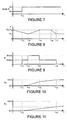
- FIG.'s 7 to 10 illustrate the effect of one embodiment of the invention in which the rate of blending is increased when driver intention is to change the amount of engine torque in the direction of the blend.
- FIG. 7 is a plot of vehicle mode as a function of time. The plot indicates a change of mode from M1 to M2 at time t 13. Mode M2 corresponds to trace B of FIG. 2 and is a more aggressive torque mapping than mode M1, which corresponds to trace A of FIG. 2 .
- FIG. 8 is a plot of accelerator pedal position as a function of time between two exemplar positions or levels P1, P2 between 0 and 100% of full travel of the accelerator pedal 261.
- a backing accelerator is advanced, and at t 15 a steady condition is assumed.
- backing is again initiated until a steady state is reached at t 17 .
- Fig. 9 is a plot of blending rate B' as a function of time. It can be seen that at the moment the mode change is initiated, a base blending rate B'base is applied. B'base is substantially equal to half the maximum available blending rate B'max that may be applied in the present embodiment although other proportions or other absolute values are also useful. The base blending rate is applied between time t 13 and time t 14 whilst the accelerator pedal 261 is not advancing.
- the maximum blending rate B'max is applied, whilst the accelerator pedal position is advancing.
- the accelerator pedal is substantially stationary whilst during the period from t 16 to t 17 the accelerator pedal 261 is backed (moved towards a less depressed position). From time t 17 the accelerator pedal 261 remains substantially stationary. Accordingly, the VCU 201C reduces the blending rate from B'max to B'base during the period from t 15 onwards, until blending is complete at time t 18 as described below.
- FIG. 10 is a plot of percent completion of blending B T as a function of time. It can be seen that the rate of blending increases significantly between times t 14 and t 15 compared with the base rate before and after this period, which reduces the overall time for completion of blending from M1 to M2. Blending can be seen to be complete at time t 18 .
- FIG. 11 is a plot of percent completion of blending B T for an embodiment in which the blending rate B' remains substantially equal to a base blending B'base throughout the period during which blending takes place. It can be seen that the time required to complete blending between modes M1 and M2 is much longer than that in the case of the embodiment described with respect to FIG.'s 7 to 10, having the blending rate profile of FIG. 9 .
- the base blending rate B'base is initiated at t 13 , so that the engine torque mapping gradually changes to meet M2. At time t18 blending is still incomplete as can be seen from FIG. 11 .
- Embodiments of the present invention have the advantage that blending can be completed more quickly than in some alternative systems. This is at least in part because the blending rate may be varied according to movement of the accelerator pedal by the driver. In some embodiments, if the accelerator pedal 261 is moved in the direction of torque change due to the mode change, the blending rate may be increased. Alternatively or in addition if the accelerator pedal 261 is held stationary or moved in a direction against the direction of torque change due to the mode change, the blending rate may be reduced, optionally substantially to zero.
Landscapes
- Engineering & Computer Science (AREA)
- Chemical & Material Sciences (AREA)
- Combustion & Propulsion (AREA)
- Mechanical Engineering (AREA)
- Transportation (AREA)
- General Engineering & Computer Science (AREA)
- Automation & Control Theory (AREA)
- Human Computer Interaction (AREA)
- Control Of Vehicle Engines Or Engines For Specific Uses (AREA)
- Electric Propulsion And Braking For Vehicles (AREA)
- Hybrid Electric Vehicles (AREA)
- Control Of Throttle Valves Provided In The Intake System Or In The Exhaust System (AREA)
- Control Of Driving Devices And Active Controlling Of Vehicle (AREA)
- Combined Controls Of Internal Combustion Engines (AREA)
Claims (15)
- Procédé de mélange entre des caractéristiques différentes de position d'accélérateur et de couple de sortie dans un véhicule, le procédé comprenant :la détection d'un premier mode de fonctionnement d'un véhicule et l'application d'une caractéristique source ;la détection d'un changement de mode de fonctionnement du véhicule et la sélection d'une caractéristique cible ;le mélange de la caractéristique appliquée de ladite caractéristique source à la caractéristique cible à un taux de mélange de base, caractérisé en ce que ledit taux de mélange est augmenté si, pendant le mélange, la position de la pédale d'accélérateur est déplacée dans la direction de changement de couple dû au mélange.
- Procédé de mélange entre des caractéristiques différentes de position d'accélérateur et de couple de sortie dans un véhicule, le procédé comprenant :la détection d'un premier mode de fonctionnement d'un véhicule et l'application d'une caractéristique source ;la détection d'un changement de mode de fonctionnement du véhicule et la sélection d'une caractéristique cible ;le mélange de la caractéristique appliquée de ladite caractéristique source à la caractéristique cible à un taux de mélange de base, caractérisé en ce que ledit taux de mélange est réduit si, pendant le mélange, la position de la pédale d'accélérateur n'est sensiblement pas déplacée, ou est déplacée à l'opposé de la direction de changement de couple dû au mélange.
- Procédé selon la revendication 1 ou la revendication 2, dans lequel le taux de mélange de base est non nul.
- Procédé selon la revendication 1, et comportant l'étape supplémentaire de réadoption dudit taux de mélange de base si la position de la pédale d'accélérateur n'est pas modifiée ou se déplace à l'opposé de la direction de changement de couple.
- Procédé selon la revendication 2, et comportant l'étape supplémentaire de réadoption dudit taux de mélange de base si la position de la pédale d'accélérateur est déplacée dans la direction de changement de couple.
- Procédé selon l'une quelconque des revendications précédentes, dans lequel ledit taux de mélange de base est variable selon la différence entre une caractéristique source et une caractéristique cible.
- Procédé selon l'une quelconque des revendications 1, 3, 4 et 6, dans lequel l'augmentation dudit taux de mélange est variable selon la différence entre une caractéristique source et une caractéristique cible.
- Procédé selon l'une quelconque de la revendication 2 ou l'une quelconque des revendications 3, 5 et 6 lorsqu'elles dépendent de la revendication 2, dans lequel la réduction dudit taux de mélange est variable selon la différence entre une caractéristique source et une caractéristique cible.
- Procédé selon l'une quelconque des revendications précédentes, dans lequel ledit taux de mélange de base est augmenté ou réduit d'un pourcentage de celui-ci.
- Procédé selon l'une quelconque des revendications précédentes, dans lequel la quantité dont le taux de mélange de base est augmentée ou réduite dépend de la position instantanée de ladite pédale d'accélérateur.
- Système de commande électronique d'un véhicule, pour un mélange entre des caractéristiques différentes de position de pédale d'accélérateur et de couple de sortie en référence à une pluralité de cartes de couple contenues dans une mémoire, ledit système étant adapté pour détecter un premier mode de fonctionnement du véhicule et appliquer une carte de couple source, détecter un changement de mode de fonctionnement du véhicule et sélectionner une carte de couple cible, et mélanger la carte de couple appliquée de ladite carte de couple source à ladite carte de couple cible à un taux de mélange de base, caractérisé en ce que ledit taux de mélange de base est augmenté si le changement de couple dû au mélange se fait dans la direction de demande du conducteur.
- Système de commande électronique d'un véhicule, pour un mélange entre des caractéristiques différentes de position de pédale d'accélérateur et de couple de sortie en référence à une pluralité de cartes de couple contenues dans une mémoire, ledit système étant adapté pour détecter un premier mode de fonctionnement du véhicule et appliquer une carte de couple source, détecter un changement de mode de fonctionnement du véhicule et sélectionner une carte de couple cible, et mélanger la carte de couple appliquée de ladite carte de couple source à ladite carte de couple cible à un taux de mélange de base, caractérisé en ce que ledit taux de mélange de base est réduit si le changement de couple dû au mélange ne se fait pas dans la direction de demande du conducteur.
- Système selon la revendication 11 ou la revendication 12, dans lequel ledit taux de mélange de base est déterminé selon la différence entre ladite carte source et ladite carte cible.
- Système selon l'une quelconque des revendications 11 à 13, dans lequel ledit taux de mélange de base est déterminé selon la position instantanée de la pédale d'accélérateur.
- Véhicule ayant un système de commande selon l'une quelconque des revendications 11 à 14, et un système de changement automatique de mode de fonctionnement d'un véhicule selon des conditions d'utilisation différentes, moyennant quoi l'une d'une pluralité de cartes de couple est sélectionnée pour chaque mode de fonctionnement.
Applications Claiming Priority (2)
| Application Number | Priority Date | Filing Date | Title |
|---|---|---|---|
| GB1201201.9A GB2498729B (en) | 2012-01-25 | 2012-01-25 | Adaptive control of internal combustion engine |
| PCT/EP2013/051440 WO2013110759A2 (fr) | 2012-01-25 | 2013-01-25 | Commande adaptative de groupe motopropulseur de véhicule automobile |
Publications (2)
| Publication Number | Publication Date |
|---|---|
| EP2807359A2 EP2807359A2 (fr) | 2014-12-03 |
| EP2807359B1 true EP2807359B1 (fr) | 2016-06-01 |
Family
ID=45840896
Family Applications (1)
| Application Number | Title | Priority Date | Filing Date |
|---|---|---|---|
| EP13707559.4A Active EP2807359B1 (fr) | 2012-01-25 | 2013-01-25 | Commande adaptative de groupe motopropulseur de véhicule automobile |
Country Status (6)
| Country | Link |
|---|---|
| US (2) | US9399396B2 (fr) |
| EP (1) | EP2807359B1 (fr) |
| JP (1) | JP6002246B2 (fr) |
| GB (1) | GB2498729B (fr) |
| WO (1) | WO2013110759A2 (fr) |
| ZA (1) | ZA201406212B (fr) |
Families Citing this family (8)
| Publication number | Priority date | Publication date | Assignee | Title |
|---|---|---|---|---|
| GB2498729B (en) | 2012-01-25 | 2014-04-09 | Jaguar Land Rover Ltd | Adaptive control of internal combustion engine |
| DE102012222482B4 (de) | 2012-12-06 | 2025-04-30 | Bayerische Motoren Werke Aktiengesellschaft | Verfahren und Vorrichtung zum verbesserten Umschalten zwischen Fahrpedalkennlinien |
| DE102016001233B4 (de) | 2016-02-04 | 2019-05-23 | Audi Ag | Intuitive Deaktivierung einer Begrenzungsfunktion |
| NL2019691B1 (en) * | 2017-10-09 | 2019-04-17 | Rassmal Invest Llc | Control device, transport apparatus, and method |
| JP7580218B2 (ja) * | 2020-07-30 | 2024-11-11 | 株式会社Subaru | 電動車両 |
| CN117355449A (zh) * | 2021-05-25 | 2024-01-05 | 舍弗勒技术股份两合公司 | 用于运行机动车的动力总成的方法 |
| JP7399593B2 (ja) * | 2021-10-26 | 2023-12-18 | ダイハツ工業株式会社 | 内燃機関の制御装置 |
| CN117962636B (zh) * | 2024-01-30 | 2025-01-24 | 重庆赛力斯凤凰智创科技有限公司 | 一种汽车单踏板滑行控制方法、装置、设备和存储介质 |
Family Cites Families (15)
| Publication number | Priority date | Publication date | Assignee | Title |
|---|---|---|---|---|
| DE3932763C1 (fr) * | 1989-09-30 | 1990-08-02 | Robert Bosch Gmbh, 7000 Stuttgart, De | |
| JPH09147294A (ja) * | 1995-11-24 | 1997-06-06 | Denso Corp | 車両制御装置及び車両制御特性付与装置 |
| GB9602731D0 (en) * | 1996-02-10 | 1996-04-10 | Ap Kongsberg Holdings Ltd | Transmission control systems |
| DE19628655C1 (de) | 1996-07-16 | 1998-01-15 | Siemens Ag | Verfahren und Vorrichtung zur Gewährleistung von stetigen Übergängen beim Wechsel von Betriebsbereichen bei Brennkraftmaschinen |
| DE10210795B4 (de) | 2002-03-12 | 2020-03-19 | Volkswagen Ag | Fahrverhaltensumschaltung |
| EP1355209A1 (fr) | 2002-04-18 | 2003-10-22 | Ford Global Technologies, LLC | Système de contrôle de véhicule |
| JP2005090452A (ja) * | 2003-09-19 | 2005-04-07 | Nissan Motor Co Ltd | マニュアルモード付き自動変速機を備えた車両制御装置 |
| US7097587B2 (en) * | 2004-08-12 | 2006-08-29 | Daimlerchrysler Corporation | Ratio selection method for a continuously variable transmission |
| US8352150B2 (en) | 2006-04-07 | 2013-01-08 | Fuji Jukogyo Kabushiki Kaisha | Engine control apparatus |
| US8352146B2 (en) | 2006-11-13 | 2013-01-08 | Ford Global Technologies, Llc | Engine response adjustment based on traffic conditions |
| JP2008168866A (ja) * | 2007-01-15 | 2008-07-24 | Toyota Motor Corp | 車両駆動装置の制御方法および制御装置 |
| US9174626B2 (en) * | 2008-01-25 | 2015-11-03 | GM Global Technology Operations LLC | Methods and systems for controlling shifting between operating modes in hybrid vehicles |
| US20110032075A1 (en) * | 2009-08-07 | 2011-02-10 | Gm Global Technology Operations, Inc. | Methods and apparatus for home-to-vehicle applications over wireless links |
| FR2962096B1 (fr) | 2010-07-02 | 2012-08-17 | Peugeot Citroen Automobiles Sa | Procede et appareil de controle/commande d'un groupe motopropulseur hybride |
| GB2498729B (en) | 2012-01-25 | 2014-04-09 | Jaguar Land Rover Ltd | Adaptive control of internal combustion engine |
-
2012
- 2012-01-25 GB GB1201201.9A patent/GB2498729B/en active Active
-
2013
- 2013-01-25 EP EP13707559.4A patent/EP2807359B1/fr active Active
- 2013-01-25 JP JP2014553730A patent/JP6002246B2/ja not_active Expired - Fee Related
- 2013-01-25 WO PCT/EP2013/051440 patent/WO2013110759A2/fr not_active Ceased
- 2013-01-25 US US14/374,378 patent/US9399396B2/en active Active
-
2014
- 2014-08-22 ZA ZA2014/06212A patent/ZA201406212B/en unknown
-
2016
- 2016-07-25 US US15/218,578 patent/US10094317B2/en active Active
Non-Patent Citations (1)
| Title |
|---|
| None * |
Also Published As
| Publication number | Publication date |
|---|---|
| WO2013110759A2 (fr) | 2013-08-01 |
| US20160333810A1 (en) | 2016-11-17 |
| ZA201406212B (en) | 2015-12-23 |
| US9399396B2 (en) | 2016-07-26 |
| US10094317B2 (en) | 2018-10-09 |
| JP6002246B2 (ja) | 2016-10-05 |
| US20140372005A1 (en) | 2014-12-18 |
| EP2807359A2 (fr) | 2014-12-03 |
| GB2498729A (en) | 2013-07-31 |
| GB201201201D0 (en) | 2012-03-07 |
| JP2015506308A (ja) | 2015-03-02 |
| WO2013110759A3 (fr) | 2013-12-27 |
| GB2498729B (en) | 2014-04-09 |
Similar Documents
| Publication | Publication Date | Title |
|---|---|---|
| US10081371B2 (en) | Adaptive control of motor vehicle powertrain | |
| EP2807359B1 (fr) | Commande adaptative de groupe motopropulseur de véhicule automobile | |
| US9849889B2 (en) | Adaptive control of motor vehicle powertrain | |
| US10202122B2 (en) | Device for controlling a vehicle | |
| CN104776212B (zh) | 无级变速器的变速控制装置 | |
| US7300384B2 (en) | Methods and devices for controlling a disk clutch | |
| US8290666B2 (en) | Method and system for controlling a vehicle engine during performance driving events | |
| JP2012187965A (ja) | 運転支援装置 | |
| US10208689B2 (en) | Adaptive control of motor vehicle powertrain | |
| CN106574712A (zh) | 自动变速器的控制装置 | |
| US7472010B2 (en) | Brake-actuating transmission control system | |
| CN108533734A (zh) | 自动变速器的变速控制装置 | |
| CN100422016C (zh) | 自动变速操作的控制系统 | |
| JP3985450B2 (ja) | 駆動力制御装置 |
Legal Events
| Date | Code | Title | Description |
|---|---|---|---|
| PUAI | Public reference made under article 153(3) epc to a published international application that has entered the european phase |
Free format text: ORIGINAL CODE: 0009012 |
|
| 17P | Request for examination filed |
Effective date: 20140825 |
|
| AK | Designated contracting states |
Kind code of ref document: A2 Designated state(s): AL AT BE BG CH CY CZ DE DK EE ES FI FR GB GR HR HU IE IS IT LI LT LU LV MC MK MT NL NO PL PT RO RS SE SI SK SM TR |
|
| DAX | Request for extension of the european patent (deleted) | ||
| REG | Reference to a national code |
Ref country code: DE Ref legal event code: R079 Ref document number: 602013008197 Country of ref document: DE Free format text: PREVIOUS MAIN CLASS: F02D0011100000 Ipc: B60K0026020000 |
|
| RIC1 | Information provided on ipc code assigned before grant |
Ipc: B60W 10/06 20060101ALI20151222BHEP Ipc: B60W 50/00 20060101ALI20151222BHEP Ipc: B60W 50/04 20060101ALI20151222BHEP Ipc: B60K 26/04 20060101ALI20151222BHEP Ipc: F02D 41/14 20060101ALI20151222BHEP Ipc: F02D 41/24 20060101ALI20151222BHEP Ipc: B60W 10/04 20060101ALI20151222BHEP Ipc: B60W 50/08 20120101ALI20151222BHEP Ipc: B60K 26/02 20060101AFI20151222BHEP Ipc: B60W 30/188 20120101ALI20151222BHEP Ipc: F02D 11/10 20060101ALI20151222BHEP |
|
| GRAP | Despatch of communication of intention to grant a patent |
Free format text: ORIGINAL CODE: EPIDOSNIGR1 |
|
| INTG | Intention to grant announced |
Effective date: 20160205 |
|
| GRAS | Grant fee paid |
Free format text: ORIGINAL CODE: EPIDOSNIGR3 |
|
| GRAA | (expected) grant |
Free format text: ORIGINAL CODE: 0009210 |
|
| AK | Designated contracting states |
Kind code of ref document: B1 Designated state(s): AL AT BE BG CH CY CZ DE DK EE ES FI FR GR HR HU IE IS IT LI LT LU LV MC MK MT NL NO PL PT RO RS SE SI SK SM TR |
|
| RBV | Designated contracting states (corrected) |
Designated state(s): AL AT BE BG CH CY CZ DE DK EE ES FI FR GR HR HU IE IS IT LI LT LU LV MC MK MT NL NO PL PT RO RS SE SI SK SM TR |
|
| REG | Reference to a national code |
Ref country code: CH Ref legal event code: EP Ref country code: AT Ref legal event code: REF Ref document number: 803665 Country of ref document: AT Kind code of ref document: T Effective date: 20160615 |
|
| REG | Reference to a national code |
Ref country code: IE Ref legal event code: FG4D |
|
| REG | Reference to a national code |
Ref country code: DE Ref legal event code: R096 Ref document number: 602013008197 Country of ref document: DE |
|
| REG | Reference to a national code |
Ref country code: LT Ref legal event code: MG4D |
|
| REG | Reference to a national code |
Ref country code: NL Ref legal event code: MP Effective date: 20160601 |
|
| PG25 | Lapsed in a contracting state [announced via postgrant information from national office to epo] |
Ref country code: LT Free format text: LAPSE BECAUSE OF FAILURE TO SUBMIT A TRANSLATION OF THE DESCRIPTION OR TO PAY THE FEE WITHIN THE PRESCRIBED TIME-LIMIT Effective date: 20160601 Ref country code: FI Free format text: LAPSE BECAUSE OF FAILURE TO SUBMIT A TRANSLATION OF THE DESCRIPTION OR TO PAY THE FEE WITHIN THE PRESCRIBED TIME-LIMIT Effective date: 20160601 Ref country code: NO Free format text: LAPSE BECAUSE OF FAILURE TO SUBMIT A TRANSLATION OF THE DESCRIPTION OR TO PAY THE FEE WITHIN THE PRESCRIBED TIME-LIMIT Effective date: 20160901 |
|
| REG | Reference to a national code |
Ref country code: AT Ref legal event code: MK05 Ref document number: 803665 Country of ref document: AT Kind code of ref document: T Effective date: 20160601 |
|
| PG25 | Lapsed in a contracting state [announced via postgrant information from national office to epo] |
Ref country code: ES Free format text: LAPSE BECAUSE OF FAILURE TO SUBMIT A TRANSLATION OF THE DESCRIPTION OR TO PAY THE FEE WITHIN THE PRESCRIBED TIME-LIMIT Effective date: 20160601 Ref country code: LV Free format text: LAPSE BECAUSE OF FAILURE TO SUBMIT A TRANSLATION OF THE DESCRIPTION OR TO PAY THE FEE WITHIN THE PRESCRIBED TIME-LIMIT Effective date: 20160601 Ref country code: NL Free format text: LAPSE BECAUSE OF FAILURE TO SUBMIT A TRANSLATION OF THE DESCRIPTION OR TO PAY THE FEE WITHIN THE PRESCRIBED TIME-LIMIT Effective date: 20160601 Ref country code: HR Free format text: LAPSE BECAUSE OF FAILURE TO SUBMIT A TRANSLATION OF THE DESCRIPTION OR TO PAY THE FEE WITHIN THE PRESCRIBED TIME-LIMIT Effective date: 20160601 Ref country code: SE Free format text: LAPSE BECAUSE OF FAILURE TO SUBMIT A TRANSLATION OF THE DESCRIPTION OR TO PAY THE FEE WITHIN THE PRESCRIBED TIME-LIMIT Effective date: 20160601 Ref country code: GR Free format text: LAPSE BECAUSE OF FAILURE TO SUBMIT A TRANSLATION OF THE DESCRIPTION OR TO PAY THE FEE WITHIN THE PRESCRIBED TIME-LIMIT Effective date: 20160902 Ref country code: RS Free format text: LAPSE BECAUSE OF FAILURE TO SUBMIT A TRANSLATION OF THE DESCRIPTION OR TO PAY THE FEE WITHIN THE PRESCRIBED TIME-LIMIT Effective date: 20160601 |
|
| REG | Reference to a national code |
Ref country code: FR Ref legal event code: PLFP Year of fee payment: 5 |
|
| PG25 | Lapsed in a contracting state [announced via postgrant information from national office to epo] |
Ref country code: IT Free format text: LAPSE BECAUSE OF FAILURE TO SUBMIT A TRANSLATION OF THE DESCRIPTION OR TO PAY THE FEE WITHIN THE PRESCRIBED TIME-LIMIT Effective date: 20160601 Ref country code: RO Free format text: LAPSE BECAUSE OF FAILURE TO SUBMIT A TRANSLATION OF THE DESCRIPTION OR TO PAY THE FEE WITHIN THE PRESCRIBED TIME-LIMIT Effective date: 20160601 Ref country code: CZ Free format text: LAPSE BECAUSE OF FAILURE TO SUBMIT A TRANSLATION OF THE DESCRIPTION OR TO PAY THE FEE WITHIN THE PRESCRIBED TIME-LIMIT Effective date: 20160601 Ref country code: EE Free format text: LAPSE BECAUSE OF FAILURE TO SUBMIT A TRANSLATION OF THE DESCRIPTION OR TO PAY THE FEE WITHIN THE PRESCRIBED TIME-LIMIT Effective date: 20160601 Ref country code: IS Free format text: LAPSE BECAUSE OF FAILURE TO SUBMIT A TRANSLATION OF THE DESCRIPTION OR TO PAY THE FEE WITHIN THE PRESCRIBED TIME-LIMIT Effective date: 20161001 Ref country code: SK Free format text: LAPSE BECAUSE OF FAILURE TO SUBMIT A TRANSLATION OF THE DESCRIPTION OR TO PAY THE FEE WITHIN THE PRESCRIBED TIME-LIMIT Effective date: 20160601 |
|
| PG25 | Lapsed in a contracting state [announced via postgrant information from national office to epo] |
Ref country code: BE Free format text: LAPSE BECAUSE OF FAILURE TO SUBMIT A TRANSLATION OF THE DESCRIPTION OR TO PAY THE FEE WITHIN THE PRESCRIBED TIME-LIMIT Effective date: 20160601 Ref country code: SM Free format text: LAPSE BECAUSE OF FAILURE TO SUBMIT A TRANSLATION OF THE DESCRIPTION OR TO PAY THE FEE WITHIN THE PRESCRIBED TIME-LIMIT Effective date: 20160601 Ref country code: AT Free format text: LAPSE BECAUSE OF FAILURE TO SUBMIT A TRANSLATION OF THE DESCRIPTION OR TO PAY THE FEE WITHIN THE PRESCRIBED TIME-LIMIT Effective date: 20160601 Ref country code: PT Free format text: LAPSE BECAUSE OF FAILURE TO SUBMIT A TRANSLATION OF THE DESCRIPTION OR TO PAY THE FEE WITHIN THE PRESCRIBED TIME-LIMIT Effective date: 20161003 Ref country code: PL Free format text: LAPSE BECAUSE OF FAILURE TO SUBMIT A TRANSLATION OF THE DESCRIPTION OR TO PAY THE FEE WITHIN THE PRESCRIBED TIME-LIMIT Effective date: 20160601 |
|
| REG | Reference to a national code |
Ref country code: DE Ref legal event code: R097 Ref document number: 602013008197 Country of ref document: DE |
|
| PLBE | No opposition filed within time limit |
Free format text: ORIGINAL CODE: 0009261 |
|
| STAA | Information on the status of an ep patent application or granted ep patent |
Free format text: STATUS: NO OPPOSITION FILED WITHIN TIME LIMIT |
|
| 26N | No opposition filed |
Effective date: 20170302 |
|
| PG25 | Lapsed in a contracting state [announced via postgrant information from national office to epo] |
Ref country code: DK Free format text: LAPSE BECAUSE OF FAILURE TO SUBMIT A TRANSLATION OF THE DESCRIPTION OR TO PAY THE FEE WITHIN THE PRESCRIBED TIME-LIMIT Effective date: 20160601 Ref country code: SI Free format text: LAPSE BECAUSE OF FAILURE TO SUBMIT A TRANSLATION OF THE DESCRIPTION OR TO PAY THE FEE WITHIN THE PRESCRIBED TIME-LIMIT Effective date: 20160601 |
|
| REG | Reference to a national code |
Ref country code: CH Ref legal event code: PL |
|
| PG25 | Lapsed in a contracting state [announced via postgrant information from national office to epo] |
Ref country code: MC Free format text: LAPSE BECAUSE OF FAILURE TO SUBMIT A TRANSLATION OF THE DESCRIPTION OR TO PAY THE FEE WITHIN THE PRESCRIBED TIME-LIMIT Effective date: 20160601 |
|
| PG25 | Lapsed in a contracting state [announced via postgrant information from national office to epo] |
Ref country code: CH Free format text: LAPSE BECAUSE OF NON-PAYMENT OF DUE FEES Effective date: 20170131 Ref country code: LI Free format text: LAPSE BECAUSE OF NON-PAYMENT OF DUE FEES Effective date: 20170131 |
|
| REG | Reference to a national code |
Ref country code: IE Ref legal event code: MM4A |
|
| PG25 | Lapsed in a contracting state [announced via postgrant information from national office to epo] |
Ref country code: LU Free format text: LAPSE BECAUSE OF NON-PAYMENT OF DUE FEES Effective date: 20170125 |
|
| REG | Reference to a national code |
Ref country code: FR Ref legal event code: PLFP Year of fee payment: 6 |
|
| PG25 | Lapsed in a contracting state [announced via postgrant information from national office to epo] |
Ref country code: IE Free format text: LAPSE BECAUSE OF NON-PAYMENT OF DUE FEES Effective date: 20170125 |
|
| PG25 | Lapsed in a contracting state [announced via postgrant information from national office to epo] |
Ref country code: MT Free format text: LAPSE BECAUSE OF NON-PAYMENT OF DUE FEES Effective date: 20170125 |
|
| PG25 | Lapsed in a contracting state [announced via postgrant information from national office to epo] |
Ref country code: AL Free format text: LAPSE BECAUSE OF FAILURE TO SUBMIT A TRANSLATION OF THE DESCRIPTION OR TO PAY THE FEE WITHIN THE PRESCRIBED TIME-LIMIT Effective date: 20160601 |
|
| PG25 | Lapsed in a contracting state [announced via postgrant information from national office to epo] |
Ref country code: HU Free format text: LAPSE BECAUSE OF FAILURE TO SUBMIT A TRANSLATION OF THE DESCRIPTION OR TO PAY THE FEE WITHIN THE PRESCRIBED TIME-LIMIT; INVALID AB INITIO Effective date: 20130125 |
|
| PG25 | Lapsed in a contracting state [announced via postgrant information from national office to epo] |
Ref country code: BG Free format text: LAPSE BECAUSE OF FAILURE TO SUBMIT A TRANSLATION OF THE DESCRIPTION OR TO PAY THE FEE WITHIN THE PRESCRIBED TIME-LIMIT Effective date: 20160601 |
|
| PG25 | Lapsed in a contracting state [announced via postgrant information from national office to epo] |
Ref country code: CY Free format text: LAPSE BECAUSE OF FAILURE TO SUBMIT A TRANSLATION OF THE DESCRIPTION OR TO PAY THE FEE WITHIN THE PRESCRIBED TIME-LIMIT Effective date: 20160601 |
|
| PG25 | Lapsed in a contracting state [announced via postgrant information from national office to epo] |
Ref country code: MK Free format text: LAPSE BECAUSE OF FAILURE TO SUBMIT A TRANSLATION OF THE DESCRIPTION OR TO PAY THE FEE WITHIN THE PRESCRIBED TIME-LIMIT Effective date: 20160601 |
|
| PG25 | Lapsed in a contracting state [announced via postgrant information from national office to epo] |
Ref country code: TR Free format text: LAPSE BECAUSE OF FAILURE TO SUBMIT A TRANSLATION OF THE DESCRIPTION OR TO PAY THE FEE WITHIN THE PRESCRIBED TIME-LIMIT Effective date: 20160601 |
|
| P01 | Opt-out of the competence of the unified patent court (upc) registered |
Effective date: 20230528 |
|
| PGFP | Annual fee paid to national office [announced via postgrant information from national office to epo] |
Ref country code: DE Payment date: 20260121 Year of fee payment: 14 |
|
| PGFP | Annual fee paid to national office [announced via postgrant information from national office to epo] |
Ref country code: FR Payment date: 20260123 Year of fee payment: 14 |