EP2806714A2 - Remote plasma system having self management function and self management method of the same - Google Patents
Remote plasma system having self management function and self management method of the same Download PDFInfo
- Publication number
- EP2806714A2 EP2806714A2 EP13182154.8A EP13182154A EP2806714A2 EP 2806714 A2 EP2806714 A2 EP 2806714A2 EP 13182154 A EP13182154 A EP 13182154A EP 2806714 A2 EP2806714 A2 EP 2806714A2
- Authority
- EP
- European Patent Office
- Prior art keywords
- plasma
- remote plasma
- generator
- remote
- generator body
- Prior art date
- Legal status (The legal status is an assumption and is not a legal conclusion. Google has not performed a legal analysis and makes no representation as to the accuracy of the status listed.)
- Withdrawn
Links
- 238000007726 management method Methods 0.000 title claims description 29
- 238000000034 method Methods 0.000 claims abstract description 91
- 230000008569 process Effects 0.000 claims abstract description 91
- 238000005259 measurement Methods 0.000 claims description 100
- 238000009413 insulation Methods 0.000 claims description 8
- 230000006698 induction Effects 0.000 claims description 6
- 238000012423 maintenance Methods 0.000 abstract description 14
- 238000009832 plasma treatment Methods 0.000 abstract description 13
- 230000002159 abnormal effect Effects 0.000 abstract description 12
- 238000004886 process control Methods 0.000 abstract 1
- 238000010586 diagram Methods 0.000 description 11
- 239000000758 substrate Substances 0.000 description 11
- 238000004519 manufacturing process Methods 0.000 description 6
- 239000004065 semiconductor Substances 0.000 description 6
- 238000009616 inductively coupled plasma Methods 0.000 description 5
- 238000005406 washing Methods 0.000 description 4
- 229910052782 aluminium Inorganic materials 0.000 description 3
- XAGFODPZIPBFFR-UHFFFAOYSA-N aluminium Chemical compound [Al] XAGFODPZIPBFFR-UHFFFAOYSA-N 0.000 description 3
- 238000004380 ashing Methods 0.000 description 3
- 239000010408 film Substances 0.000 description 3
- 238000012986 modification Methods 0.000 description 3
- 230000004048 modification Effects 0.000 description 3
- PXHVJJICTQNCMI-UHFFFAOYSA-N Nickel Chemical compound [Ni] PXHVJJICTQNCMI-UHFFFAOYSA-N 0.000 description 2
- 239000000919 ceramic Substances 0.000 description 2
- 230000008021 deposition Effects 0.000 description 2
- 238000000151 deposition Methods 0.000 description 2
- 238000005530 etching Methods 0.000 description 2
- 150000002500 ions Chemical class 0.000 description 2
- 239000007769 metal material Substances 0.000 description 2
- 238000012544 monitoring process Methods 0.000 description 2
- 239000010453 quartz Substances 0.000 description 2
- VYPSYNLAJGMNEJ-UHFFFAOYSA-N silicon dioxide Inorganic materials O=[Si]=O VYPSYNLAJGMNEJ-UHFFFAOYSA-N 0.000 description 2
- RYGMFSIKBFXOCR-UHFFFAOYSA-N Copper Chemical compound [Cu] RYGMFSIKBFXOCR-UHFFFAOYSA-N 0.000 description 1
- 230000008901 benefit Effects 0.000 description 1
- 230000008859 change Effects 0.000 description 1
- 229910052802 copper Inorganic materials 0.000 description 1
- 239000010949 copper Substances 0.000 description 1
- 238000000354 decomposition reaction Methods 0.000 description 1
- 230000006866 deterioration Effects 0.000 description 1
- 238000010292 electrical insulation Methods 0.000 description 1
- 239000012772 electrical insulation material Substances 0.000 description 1
- 230000005284 excitation Effects 0.000 description 1
- 239000011521 glass Substances 0.000 description 1
- 239000012774 insulation material Substances 0.000 description 1
- 239000000463 material Substances 0.000 description 1
- 229910052751 metal Inorganic materials 0.000 description 1
- 239000002184 metal Substances 0.000 description 1
- 229910052759 nickel Inorganic materials 0.000 description 1
- 239000002245 particle Substances 0.000 description 1
- 229920002120 photoresistant polymer Polymers 0.000 description 1
- 238000012545 processing Methods 0.000 description 1
- 239000003870 refractory metal Substances 0.000 description 1
- 229910001220 stainless steel Inorganic materials 0.000 description 1
- 239000010935 stainless steel Substances 0.000 description 1
- 238000006467 substitution reaction Methods 0.000 description 1
- 239000010409 thin film Substances 0.000 description 1
Images
Classifications
-
- H—ELECTRICITY
- H01—ELECTRIC ELEMENTS
- H01J—ELECTRIC DISCHARGE TUBES OR DISCHARGE LAMPS
- H01J37/00—Discharge tubes with provision for introducing objects or material to be exposed to the discharge, e.g. for the purpose of examination or processing thereof
- H01J37/32—Gas-filled discharge tubes
- H01J37/32917—Plasma diagnostics
- H01J37/32935—Monitoring and controlling tubes by information coming from the object and/or discharge
-
- G—PHYSICS
- G01—MEASURING; TESTING
- G01R—MEASURING ELECTRIC VARIABLES; MEASURING MAGNETIC VARIABLES
- G01R19/00—Arrangements for measuring currents or voltages or for indicating presence or sign thereof
- G01R19/0046—Arrangements for measuring currents or voltages or for indicating presence or sign thereof characterised by a specific application or detail not covered by any other subgroup of G01R19/00
- G01R19/0061—Measuring currents of particle-beams, currents from electron multipliers, photocurrents, ion currents; Measuring in plasmas
-
- H—ELECTRICITY
- H01—ELECTRIC ELEMENTS
- H01J—ELECTRIC DISCHARGE TUBES OR DISCHARGE LAMPS
- H01J37/00—Discharge tubes with provision for introducing objects or material to be exposed to the discharge, e.g. for the purpose of examination or processing thereof
- H01J37/32—Gas-filled discharge tubes
- H01J37/32009—Arrangements for generation of plasma specially adapted for examination or treatment of objects, e.g. plasma sources
- H01J37/32357—Generation remote from the workpiece, e.g. down-stream
-
- H—ELECTRICITY
- H01—ELECTRIC ELEMENTS
- H01J—ELECTRIC DISCHARGE TUBES OR DISCHARGE LAMPS
- H01J37/00—Discharge tubes with provision for introducing objects or material to be exposed to the discharge, e.g. for the purpose of examination or processing thereof
- H01J37/32—Gas-filled discharge tubes
- H01J37/32917—Plasma diagnostics
- H01J37/3299—Feedback systems
-
- H—ELECTRICITY
- H05—ELECTRIC TECHNIQUES NOT OTHERWISE PROVIDED FOR
- H05H—PLASMA TECHNIQUE; PRODUCTION OF ACCELERATED ELECTRICALLY-CHARGED PARTICLES OR OF NEUTRONS; PRODUCTION OR ACCELERATION OF NEUTRAL MOLECULAR OR ATOMIC BEAMS
- H05H1/00—Generating plasma; Handling plasma
- H05H1/24—Generating plasma
- H05H1/46—Generating plasma using applied electromagnetic fields, e.g. high frequency or microwave energy
- H05H1/461—Microwave discharges
- H05H1/463—Microwave discharges using antennas or applicators
Definitions
- the present invention relates to a plasma processing system, and particularly, to a remote plasma system that performs a plasma treatment process in a process chamber by remotely receiving plasma generated through a remote plasma generator.
- Plasma discharge is used in gas excitation for generating active gas containing ions, free radicals, atoms, and molecules.
- the active gas is widely used in various fields and representatively variously used in a semiconductor manufacturing process, for example, etching, deposition, washing, ashing, and the like.
- a remote plasma generator is a device that generates plasma outside a process chamber to remotely supply the generated plasma to the process chamber.
- a representative semiconductor manufacturing process using the remote plasma generator includes, for example, a washing process for washing the inside of the process chamber and an ashing process for removing a photoresist film deposited on a substrate to be treated.
- the remote plasma generator is used even in various other semiconductor manufacturing processes.
- maintenance efficiency of process equipment is one of the very important elements in terms of productivity and cost.
- an equipment use time when the equipment normally operates is calculated in advance to periodically maintain the equipment after using the equipment for a predetermined time.
- the remote plasma generator after the remote plasma generator is used for a predetermined time, maintenance such as replacement of a time-worn part or replacement of the equipment itself is required. The maintenance may be required even for another reason. For example, after a substrate treatment process is completed, when a problem occurs in a treatment result thereof, it may be recognized that the maintenance of the equipment is required.
- a maintenance time of the equipment is, in advance, predicted by determining an operating state of the equipment in real time to cope with the problem before the problem occurs in the process.
- the remote plasma generator so far may not provide appropriate information on an equipment state and a process progress state, it is very difficult to execute the maintenance at an appropriate time. Therefore, it is necessary that a process manager can immediately cope with problems, which occur while the process is in progress, by monitoring the operating state of the remote plasma generator and the plasma treatment process in real time and sensing the problems in real time while the remote plasma generator is connection with the process chamber and operates.
- the present invention has been made in an effort to provide a remote plasma system having a self management function and a self management method of the same that can check operating state information of a remote plasma generator in real time to judge whether the remote plasma generator normally operates and immediately sense occurrence of an error during an operation.
- the present invention has also been made in an effort to provide a remote plasma system having a self management function and a self management method of the same that can check operating state information of a remote plasma generator and plasma treatment process progress state information in a process chamber in real time while plasma generated from the remote plasma generator is supplied to the process chamber.
- An exemplary embodiment of the present invention provides a remote plasma system having a self management function.
- the remote plasma system includes: a remote plasma generator generating plasma and remotely supplying the generated plasma to a process chamber; a sensor unit including one or more voltage measurement sensors for measuring voltage induced to a generator body of the remote plasma generator; and a control unit generating operating state information of the remote plasma generator based on voltage values measured by the one or more voltage measurement sensors.
- the sensor unit may include one or more current measurement sensors measuring current which leaks through the generator body of the remote plasma generator, and the control unit may generate another operating state information based on a leakage current measurement value measured by the current measurement sensor.
- the sensor unit may include a current transformer installed around a gas outlet of the remote plasma generator, and the control unit may generate another operating state information based on a current measurement value measured through the current transformer.
- the sensor unit may include a plasma measurement sensor measuring plasma generated in the generator body of the remote plasma generator, and the control unit may generate another operating state information of the remote plasma generator based on a plasma measurement value measured through the plasma measurement sensor.
- the sensor unit may include a plasma measurement sensor measuring a state of plasma that flows into the process chamber, and the control unit may generate process progress state information in the process chamber based on a plasma measurement value measured by the plasma measurement sensor.
- the sensor unit may include a plasma measurement sensor measuring a plasma state of exhaust gas which is exhausted from the process chamber, and the control unit may generate process progress state information in the process chamber based on a plasma measurement value measured by the plasma measurement sensor.
- the remote plasma generator may include: a generator body having a plasma discharge space; a transformer having a magnetic core and a primary wire wound to the magnetic core which are installed in the generator body so as to supply electromotive force for forming plasma to the plasma discharge space of the generator body; and a power supply source supplying driving power to the primary wire of the transformer.
- the remote plasma system may further include a capacitively coupled electrode that is installed in the generator body so as to supply the electromotive force for forming the plasma to the plasma discharge space of the generator body and operates by receiving the driving power from the power supply source.
- the remote plasma system may further include an induction antenna coil that is installed in the generator body so as to supply the electromotive force for forming the plasma to the plasma discharge space of the generator body and operates by receiving the driving power from the power supply source.
- the remote plasma generator may include a metallic generator body having two or more divided regions divided into one or more insulation sections, and the voltage measurement sensor may include two or more voltage measurement sensors installed in each of the two or more divided regions of the generator body.
- the remote plasma generator may include a metallic generator body having the plasma discharge space and two or more divided regions divided into one or more insulation sections, and the current measurement sensor may include two or more current measurement sensors installed in the two or more divided regions of the generator body.
- the self management method of the remote plasma system includes: starting an operation of a remote plasma generator; measuring voltage induced to a generator body of the remote plasma generator through a sensor unit including one or more voltage measurement sensors; and generating operating state information of the remote plasma generator based on a voltage measurement value induced to the generator body of the remote plasma generator, which is measured by the sensor unit.
- the self management method may further include, wherein the sensor unit includes a current measurement sensor measuring current which leaks through the generator body of the remote plasma generator, generating another operating state information based on a leakage current measurement value measured by the current measurement sensor.
- the sensor unit includes a current measurement sensor measuring current which leaks through the generator body of the remote plasma generator, generating another operating state information based on a leakage current measurement value measured by the current measurement sensor.
- the self management method may further include, wherein the sensor unit includes a current transformer installed around a gas outlet of the remote plasma generator, generating another operating state information based on a measurement value measured by the current transformer.
- the self management method may further include, wherein the sensor unit includes a plasma measurement sensor measuring plasma generated in the generator body of the remote plasma generator, generating another operating state information based on a plasma measurement value measured by the plasma measurement sensor.
- the sensor unit includes a plasma measurement sensor measuring plasma generated in the generator body of the remote plasma generator, generating another operating state information based on a plasma measurement value measured by the plasma measurement sensor.
- the self management method may further include, wherein the sensor unit includes a plasma measurement sensor measuring a plasma state in the process chamber, generating process progress state information in the process chamber based on a plasma measurement value measured by the plasma measurement sensor.
- the sensor unit includes a plasma measurement sensor measuring a plasma state in the process chamber, generating process progress state information in the process chamber based on a plasma measurement value measured by the plasma measurement sensor.
- the self management method may further include, wherein the sensor unit includes a plasma measurement sensor measuring a plasma state of exhaust gas which is exhausted from the process chamber, generating process progress state information in the process chamber based on a plasma measurement value measured by the plasma measurement sensor.
- the sensor unit includes a plasma measurement sensor measuring a plasma state of exhaust gas which is exhausted from the process chamber, generating process progress state information in the process chamber based on a plasma measurement value measured by the plasma measurement sensor.
- a remote plasma system having a self management function and a self management method of the same of the present invention, it is possible to check operating state information of a remote plasma generator in real time to judge whether the remote plasma generator normally operates and immediately sense occurrence of an error during the operation. Further, it is possible to check in real time operating state information of the remote plasma generator and plasma treatment process progress state information in a process chamber while the plasma generated from the remote plasma generator is supplied to the process chamber.
- a process manager can determine an operating state of the remote plasma system in real time and immediately cope with an abnormal operation when the abnormal operation occurs. Further, the process manager can determine the system in real time at the time when maintenance of the system is required, thereby increasing maintenance efficiency.
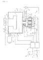
- FIG. 1 is a diagram illustrating an overall configuration of a remote plasma system having a self management function according to an exemplary embodiment of the present invention.
- a predetermined plasma treatment process is performed in the process chamber 10.
- the process chamber 10 may be any one of the equipment for performing various plasma treatment processes such as etching, deposition, ashing, or surface modification for forming a thin film on a substrate 14 to be treated.
- the remote plasma generator 60 is used to perform not only the plasma treatment process for the substrate 14 to be treated but also the plasma treatment process for internal washing of the process chamber 10.
- the remote plasma system of the present invention has a self management function to immediately sense whether the remote plasma generator 60 normally operates, whether an error occurs during the operation, and the necessity of maintenance by measuring the operating state of the remote plasma generator 60 and the state of the plasma generated from the remote plasma generator 60 while the plasma treatment process is performed in real time.
- the process chamber 10 includes a process chamber housing 11 and a substrate supporter 12 in which the substrate 14 to be treated is placed.
- the substrate 14 to be treated may be, for example, various types of wafer substrates or glass substrates for manufacturing a semiconductor device.
- a gas inlet 15 of the process chamber 10 is connected to a gas outlet 66 of the remote plasma generator 60 through an adapter 67.
- a gas exhaust port 16 provided at a lower portion of the process chamber 10 is connected to a vacuum pump 20 through an exhaust pipe 22.
- the process chamber 10 may include a plasma source 17 for generating plasma therein, and a power supply source 30 and an impedance matcher 32 for the plasma source 17.
- the plasma generated from the remote plasma generator 60 is supplied to the inside of the process chamber housing 11 through the adapter 67, and as a result, a predetermined plasma treatment process is performed.
- the plasma supplied from the remote plasma generator 60 may be evenly distributed to the process chamber 10 through a baffle (not illustrated) provided in the process chamber 10.
- the substrate supporter 12 on which the substrate 14 to be treated is placed may be connected to a bias power supply source 34 through an impedance matcher 36.
- the remote plasma generator 60 includes a generator body 61 having a toroidal shape plasma discharge space.
- a transformer 75 having a magnetic core 76 and a primary wire 77 wound thereto so as to supply electromotive force for forming the plasma in the plasma discharge space is mounted on the generator body 61.
- the primary wire 77 is connected to a power supply source 68.
- the power supply source 68 includes a semiconductor switching circuit and generates radio-frequency power therethrough to supply the radio-frequency power to the primary wire 77.
- the power supply source 68 may include a control circuit for impedance matching or may supply the radio-frequency power to the primary wire 77 through an additional impedance matcher.
- the power supply source 68 and the generator body 61 may be integrally configured or may be separated from each other.
- the remote plasma system of the present invention includes a sensor unit constituted by a plurality of sensors for measuring an operating state of the remote plasma generator 60 and a control unit 70 generating operating state information of the remote plasma generator 60 based on an electric characteristic value measured by the sensor unit.
- the sensor unit includes one or more voltage measurement sensors 40 and 42 that measure voltage induced to the generator body 61.
- the voltage measurement sensors 40 and 42 measures the voltage induced to the generator body 61 while the remote plasma generator 60 operates and supplies the measurement voltage to the control unit 70.
- the sensor unit may further include one or more current measurement sensors 44.
- the voltage measurement sensor 44 measures current that flows on the generator body 61 which may be generated while the remote plasma generator 60 operates and supplies the measured current to the control unit 70.
- the sensor unit may further include a current transformer 44.
- the current transformer 44 is installed around the gas outlet 66 of the remote plasma generator 60 (for example, so that a core of the current transformer 44 surrounds the adapter 67).
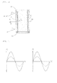
- FIG. 2 is a cross-sectional view partially illustrating the generator body of the remote plasma generator
- FIG. 3 is a voltage and current waveform diagram exemplarily illustrating normal values and abnormal values of voltage and current measured in the generator body of the remote plasma generator which are compared with each other.
- a cause of when the abnormal state occurs may be diversified and may include, for example, a case in which initial ignition fails, a case in which plasma is off, a case in which a plasma state is unstable, a case in which an internal protection film 69 of the generator body 61 is damaged, a case in which arc is generated inside the generator body 61, a case in which power supplying is unstable, and the like.
- the remote plasma generator 60 starts an operation, the electromotive force for generating plasma is transferred to the inside of the generator body 61 and voltage is induced even to the generator body 61 while plasma is generated.
- the remote plasma generator 60 is in a normal state, the voltage induced to the generator body 61 is detected in a normal form.
- the remote plasma generator 60 is in an abnormal state by a predetermined cause, the voltage induced to the generator body 61 is measured in an abnormal form.
- the voltage measured in the generator body 61 is measured in the abnormal form.
- the internal protection film 69 of the generator body 61 is damaged (marked by a dotted-line circle 'A' in FIG. 2 )
- leakage current may be generated through the generator body 61.
- the leakage current may be detected by the current measurement sensor 46.
- the voltage induced to the generator body 61 may fluctuate. Since the inside of the generator body 61 is damaged by an impact of plasma ion particles, the remote plasma generator 60 has a reduced life-span.
- the leakage current is measured by the current measurement sensor 46 to diagnose the life-span of the generator body 61.
- the current transformer 44 is installed in the adapter 67 and measures a change in current while the plasma gas is supplied to the process chamber 10, so as to provide the measurement value to the control unit 70.
- the current transformer 44 provides a normal current measurement value while normal plasma gas is supplied to the process chamber 10 from the remote plasma generator 60, but provides an abnormal current measurement value when the plasma gas is abnormally supplied.
- the control unit 70 generates the operating state information of the remote plasma generator 60 based on one or more values of the measurement values provided from the voltage measurement sensors 40 and 42, the current measurement sensors 44 and 46, and the current transformer 44 that constitute the sensor unit.
- the generated operating state information of the remote plasma generator 60 may be displayed through a state display unit 72 or provided to a host 74 that controls and manages the whole system.
- the state display unit 72 may include a display device for displaying a screen and a speaker device for displaying a voice.
- the control unit 70 may control an overall operation of the remote plasma system as necessary, and warn an operator of the necessity for maintenance through the state display unit 72 or perform a control required for an overall operation of the system, when an error occurs during the operation. For example, the control unit 70 may stop the operation of the system by stopping operations of various power supply sources 30, 34, and 68 in case of emergency.
- the sensor unit may include a plasma measurement sensor for optically or electrically measuring the plasma generated by the remote plasma generator 60.
- the plasma measurement sensor is installed in the generator body 61 or the adapter 67 to measure a state of the plasma generated by the remote plasma generator 60 and provide the measured state to the control unit 70 while the remote plasma generator 60 operates.
- the control unit 70 generates another operating state information of the remote plasma generator 60 and performs a state display and a required control through the state display unit 72, based on the plasma measurement value measured through the plasma measurement sensor.
- the sensor unit may include other plasma measurement sensors 18 and 19 for optically or electrically measuring the plasma in the process chamber 10 while the plasma is treated in the process chamber 10.
- the sensor unit may include the plasma measurement sensor 18 for measuring an internal plasma state of the process chamber 10 and the plasma measurement sensor 19 for measuring a state of plasma which is exhausted from the process chamber 10.
- the control unit 70 generates process progress state information in the process chamber 10 based on the plasma measurement values measured through the plasma measurement sensors 18 and 19 to display the generated process progress state information through the state display unit 72 and perform a required control. For example, a process progress state and a process completion state or an error state may be judged by measuring a process decomposition rate by plasma.
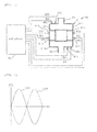
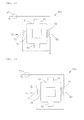
- FIG. 4 is a diagram exemplarily illustrating a case in which voltage and current are measured in respective regions when the generator body of the remote plasma generator is divided into a plurality of insulation sections
- FIG. 5 is a voltage waveform diagram exemplarily illustrating voltage measured in different parts of the generator body of the remote plasma generator.
- the generator body 61 of the remote plasma generator 60 is made of metallic materials such as aluminum, stainless steel, and copper.
- the generator body 61 may be made of coated metal such as anodized aluminum or nickel plated aluminum.
- the generator body 61 may be made of refractory metal.
- the generator body 61 may be made of insulation materials such as quartz and ceramic and even other materials suitable to perform an intended plasma process.
- the generator body 61 includes one or more electrical insulation regions 62, which provides electrical discontinuity, in order to prevent eddy current from being generated when the generator body 61 includes the metallic materials.
- the insulation region 62 is made of electrical insulation materials such as quartz and ceramic.
- voltage measurement sensors 47a, 47b, 47c, and 47d and current measurement sensors 48a, 48b, 48c, and 48d may be installed in the respective regions.
- a voltage waveform VS1 detected by the first voltage measurement sensor 47a installed in the first region 61a and a voltage waveform VS2 detected by the second voltage measurement sensor 47b installed in the second region 61b may have phases inverse to each other.
- the voltage and the current measured by the voltage measurement sensors 47a, 47b, 47c, and 47d and the current measurement sensors 48a, 48b, 48c, and 48d installed in the first to four regions 61a, 61b, 61c, and 61d are detected as a predetermined phase difference and a predetermined size with which the remote plasma generator 60 normally operates.
- the voltage or current measured by the voltage measurement sensors 47a, 47b, 47c, and 47d and the current measurement sensors 48a, 48b, 48c, and 48d varies in phase difference or size measured in the normal state.
- the control unit 70 judges whether the remote plasma generator 60 normally operates, based on the variation component, displays the operating state through the state display unit 70, and performs the required control.
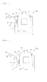
- FIGS. 6 to 9 are diagrams exemplarily illustrating various types of remote plasma generators which may be adopted in the remote plasma system of the present invention.
- a magnetic core 76 and a transformer 75 having a primary wire 77 wound thereto are mounted on remote plasma generators 60a and 60b, which may be adopted in the remote plasma system of the present invention, so as to supply the electromotive force for forming plasma in the plasma discharge space of the generator body 61.
- Remote plasma generators 60a and 60b may further include capacitively coupled electrodes 80 and 81 that are installed in the generator body 61 so as to supply the electromotive force for forming plasma to the plasma discharge space of the generator body 61 and operates by receiving driving power from the power supply source 67.
- the primary wire 77 and the capacitively coupled electrodes 80 and 81 may be connected to the power supply source 67 in parallel (an example illustrated in FIG. 6 ) or in series (an example illustrated in FIG. 7 ).
- the magnetic core 76 and the transformer 75 having the primary wire 77 wound thereto are mounted on other remote plasma generators 60c and 60d, which may be adopted in the remote plasma system of the present invention, so as to supply the electromotive force for forming plasma in the plasma discharge space of the generator body 61.
- the remote plasma generators 60c and 60d may further include an induction antenna coil 82 that is installed in the generator body 61 so as to supply the electromotive force for forming plasma to the plasma discharge space of the generator body 61 and operates by receiving driving power from the power supply source 67.
- a dielectric window 83 may be installed so as to induce the electromotive force into a part in which the induction antenna coil 82 is installed.
- the primary wire 77 and the induction antenna coil 82 may be connected to the power supply source 67 in parallel (an example illustrated in FIG. 8 ) or in series (an example illustrated in FIG. 9 ).
- a plasma source of a hybrid type may be used in which capacitively coupled plasma or inductively coupled plasma is mixed in addition to a transformer coupled plasma type.
- the hybrid type plasma source When the hybrid type plasma source is adopted, remote plasma may be more stably generated.
- any one type among various types of remote plasma generation types such as, for example, the transformer coupled plasma, the coactively coupled plasma, the inductively coupled plasma, and microwave plasma may be applied a.
Abstract
Description
- This application claims priority to and the benefit of Korean Patent Application No.
10-2013-0057759 - The present invention relates to a plasma processing system, and particularly, to a remote plasma system that performs a plasma treatment process in a process chamber by remotely receiving plasma generated through a remote plasma generator.
- Plasma discharge is used in gas excitation for generating active gas containing ions, free radicals, atoms, and molecules. The active gas is widely used in various fields and representatively variously used in a semiconductor manufacturing process, for example, etching, deposition, washing, ashing, and the like.
- A remote plasma generator is a device that generates plasma outside a process chamber to remotely supply the generated plasma to the process chamber. A representative semiconductor manufacturing process using the remote plasma generator includes, for example, a washing process for washing the inside of the process chamber and an ashing process for removing a photoresist film deposited on a substrate to be treated. In addition, the remote plasma generator is used even in various other semiconductor manufacturing processes.
- In the semiconductor manufacturing process, maintenance efficiency of process equipment is one of the very important elements in terms of productivity and cost. in general, in the case of maintenance of the process equipment, an equipment use time when the equipment normally operates is calculated in advance to periodically maintain the equipment after using the equipment for a predetermined time. Even in the case of the remote plasma generator, after the remote plasma generator is used for a predetermined time, maintenance such as replacement of a time-worn part or replacement of the equipment itself is required. The maintenance may be required even for another reason. For example, after a substrate treatment process is completed, when a problem occurs in a treatment result thereof, it may be recognized that the maintenance of the equipment is required.
- However, when the necessity of the maintenance of the equipment is recognized by sensing a treatment error, unnecessary production cost may be generated with deterioration in productivity. Further, if the equipment is normally usable even when the equipment is periodically maintained after being used for a predetermined time, unnecessary cost may be generated. Therefore, most preferably, a maintenance time of the equipment is, in advance, predicted by determining an operating state of the equipment in real time to cope with the problem before the problem occurs in the process.
- While the plasma generated from the remote plasma generator is supplied to the process chamber to perform the plasma treatment process, appropriate monitoring of the operating state of the remote plasma generator and the plasma treatment process is required. However, since the remote plasma generator so far may not provide appropriate information on an equipment state and a process progress state, it is very difficult to execute the maintenance at an appropriate time. Therefore, it is necessary that a process manager can immediately cope with problems, which occur while the process is in progress, by monitoring the operating state of the remote plasma generator and the plasma treatment process in real time and sensing the problems in real time while the remote plasma generator is connection with the process chamber and operates.
- The present invention has been made in an effort to provide a remote plasma system having a self management function and a self management method of the same that can check operating state information of a remote plasma generator in real time to judge whether the remote plasma generator normally operates and immediately sense occurrence of an error during an operation.
- The present invention has also been made in an effort to provide a remote plasma system having a self management function and a self management method of the same that can check operating state information of a remote plasma generator and plasma treatment process progress state information in a process chamber in real time while plasma generated from the remote plasma generator is supplied to the process chamber.
- An exemplary embodiment of the present invention provides a remote plasma system having a self management function. The remote plasma system includes: a remote plasma generator generating plasma and remotely supplying the generated plasma to a process chamber; a sensor unit including one or more voltage measurement sensors for measuring voltage induced to a generator body of the remote plasma generator; and a control unit generating operating state information of the remote plasma generator based on voltage values measured by the one or more voltage measurement sensors.
- The sensor unit may include one or more current measurement sensors measuring current which leaks through the generator body of the remote plasma generator, and the control unit may generate another operating state information based on a leakage current measurement value measured by the current measurement sensor.
- The sensor unit may include a current transformer installed around a gas outlet of the remote plasma generator, and the control unit may generate another operating state information based on a current measurement value measured through the current transformer.
- The sensor unit may include a plasma measurement sensor measuring plasma generated in the generator body of the remote plasma generator, and the control unit may generate another operating state information of the remote plasma generator based on a plasma measurement value measured through the plasma measurement sensor.
- The sensor unit may include a plasma measurement sensor measuring a state of plasma that flows into the process chamber, and the control unit may generate process progress state information in the process chamber based on a plasma measurement value measured by the plasma measurement sensor.
- The sensor unit may include a plasma measurement sensor measuring a plasma state of exhaust gas which is exhausted from the process chamber, and the control unit may generate process progress state information in the process chamber based on a plasma measurement value measured by the plasma measurement sensor.
- The remote plasma generator may include: a generator body having a plasma discharge space; a transformer having a magnetic core and a primary wire wound to the magnetic core which are installed in the generator body so as to supply electromotive force for forming plasma to the plasma discharge space of the generator body; and a power supply source supplying driving power to the primary wire of the transformer.
- The remote plasma system may further include a capacitively coupled electrode that is installed in the generator body so as to supply the electromotive force for forming the plasma to the plasma discharge space of the generator body and operates by receiving the driving power from the power supply source.
- The remote plasma system may further include an induction antenna coil that is installed in the generator body so as to supply the electromotive force for forming the plasma to the plasma discharge space of the generator body and operates by receiving the driving power from the power supply source.
- The remote plasma generator may include a metallic generator body having two or more divided regions divided into one or more insulation sections, and the voltage measurement sensor may include two or more voltage measurement sensors installed in each of the two or more divided regions of the generator body.
- The remote plasma generator may include a metallic generator body having the plasma discharge space and two or more divided regions divided into one or more insulation sections, and the current measurement sensor may include two or more current measurement sensors installed in the two or more divided regions of the generator body.
- Another exemplary embodiment of the present invention provides a self management method of a remote plasma system having a self management function. The self management method of the remote plasma system includes: starting an operation of a remote plasma generator; measuring voltage induced to a generator body of the remote plasma generator through a sensor unit including one or more voltage measurement sensors; and generating operating state information of the remote plasma generator based on a voltage measurement value induced to the generator body of the remote plasma generator, which is measured by the sensor unit.
- The self management method may further include, wherein the sensor unit includes a current measurement sensor measuring current which leaks through the generator body of the remote plasma generator, generating another operating state information based on a leakage current measurement value measured by the current measurement sensor.
- The self management method may further include, wherein the sensor unit includes a current transformer installed around a gas outlet of the remote plasma generator, generating another operating state information based on a measurement value measured by the current transformer.
- The self management method may further include, wherein the sensor unit includes a plasma measurement sensor measuring plasma generated in the generator body of the remote plasma generator, generating another operating state information based on a plasma measurement value measured by the plasma measurement sensor.
- The self management method may further include, wherein the sensor unit includes a plasma measurement sensor measuring a plasma state in the process chamber, generating process progress state information in the process chamber based on a plasma measurement value measured by the plasma measurement sensor.
- The self management method may further include, wherein the sensor unit includes a plasma measurement sensor measuring a plasma state of exhaust gas which is exhausted from the process chamber, generating process progress state information in the process chamber based on a plasma measurement value measured by the plasma measurement sensor.
- According to a remote plasma system having a self management function and a self management method of the same of the present invention, it is possible to check operating state information of a remote plasma generator in real time to judge whether the remote plasma generator normally operates and immediately sense occurrence of an error during the operation. Further, it is possible to check in real time operating state information of the remote plasma generator and plasma treatment process progress state information in a process chamber while the plasma generated from the remote plasma generator is supplied to the process chamber.
- Therefore, a process manager can determine an operating state of the remote plasma system in real time and immediately cope with an abnormal operation when the abnormal operation occurs. Further, the process manager can determine the system in real time at the time when maintenance of the system is required, thereby increasing maintenance efficiency.
-
-
FIG. 1 is a diagram illustrating an overall configuration of a remote plasma system having a self management function according to an exemplary embodiment of the present invention. -
FIG. 2 is a cross-sectional view partially illustrating a generator body of the remote plasma generator. -
FIG. 3 is a voltage and current waveform diagram exemplarily illustrating normal values and abnormal values of voltage and current measured in the generator body of the remote plasma generator which are compared with each other. -
FIG. 4 is a diagram exemplarily illustrating a case in which voltage and current are measured in respective regions when the generator body of the remote plasma generator is divided into a plurality of insulation sections. -
FIG. 5 is a voltage waveform diagram exemplarily illustrating voltage measured in different parts of the generator body of the remote plasma generator. -
FIGS. 6 to 9 are diagrams exemplarily illustrating various types of remote plasma generators which may be adopted in the remote plasma system of the present invention. - Exemplary embodiments of the present invention will be described with reference to the accompanying drawings in order to sufficiently understand the present invention. The exemplary embodiments of the present invention can be modified in various forms, and it should not be construed that the scope of the present invention is limited to exemplary embodiments described below in detail. The exemplary embodiments are provided to more completely describe the present invention to those skilled in the art. Therefore, shapes of elements in the drawings may be enlarged in order to emphasize a more clear description. It is noted that like reference numerals refer to like elements in each drawing. A detailed description of known functions and configurations judged to unnecessarily obscure the spirit of the present invention will be omitted.
-
FIG. 1 is a diagram illustrating an overall configuration of a remote plasma system having a self management function according to an exemplary embodiment of the present invention. - Referring to
FIG. 1 , in the remote plasma system according to the exemplary embodiment of the present invention, while plasma generated from aremote plasma generator 60 is supplied to aprocess chamber 10, a predetermined plasma treatment process is performed in theprocess chamber 10. Theprocess chamber 10 may be any one of the equipment for performing various plasma treatment processes such as etching, deposition, ashing, or surface modification for forming a thin film on asubstrate 14 to be treated. Theremote plasma generator 60 is used to perform not only the plasma treatment process for thesubstrate 14 to be treated but also the plasma treatment process for internal washing of theprocess chamber 10. The remote plasma system of the present invention has a self management function to immediately sense whether theremote plasma generator 60 normally operates, whether an error occurs during the operation, and the necessity of maintenance by measuring the operating state of theremote plasma generator 60 and the state of the plasma generated from theremote plasma generator 60 while the plasma treatment process is performed in real time. - The
process chamber 10 includes aprocess chamber housing 11 and asubstrate supporter 12 in which thesubstrate 14 to be treated is placed. Thesubstrate 14 to be treated may be, for example, various types of wafer substrates or glass substrates for manufacturing a semiconductor device. Agas inlet 15 of theprocess chamber 10 is connected to agas outlet 66 of theremote plasma generator 60 through anadapter 67. Agas exhaust port 16 provided at a lower portion of theprocess chamber 10 is connected to avacuum pump 20 through anexhaust pipe 22. Although not illustrated in the figure in detail, theprocess chamber 10 may include aplasma source 17 for generating plasma therein, and apower supply source 30 and animpedance matcher 32 for theplasma source 17. The plasma generated from theremote plasma generator 60 is supplied to the inside of theprocess chamber housing 11 through theadapter 67, and as a result, a predetermined plasma treatment process is performed. The plasma supplied from theremote plasma generator 60 may be evenly distributed to theprocess chamber 10 through a baffle (not illustrated) provided in theprocess chamber 10. Thesubstrate supporter 12 on which thesubstrate 14 to be treated is placed may be connected to a biaspower supply source 34 through animpedance matcher 36. - For the
remote plasma generator 60, various plasma generation types may be used, and in the exemplary embodiment, a transformer coupled plasma generation typeremote plasma generator 60 is exemplified, but the present invention is not limited thereto. Theremote plasma generator 60 includes agenerator body 61 having a toroidal shape plasma discharge space. Atransformer 75 having amagnetic core 76 and aprimary wire 77 wound thereto so as to supply electromotive force for forming the plasma in the plasma discharge space is mounted on thegenerator body 61. Theprimary wire 77 is connected to apower supply source 68. Thepower supply source 68 includes a semiconductor switching circuit and generates radio-frequency power therethrough to supply the radio-frequency power to theprimary wire 77. Thepower supply source 68 may include a control circuit for impedance matching or may supply the radio-frequency power to theprimary wire 77 through an additional impedance matcher. Thepower supply source 68 and thegenerator body 61 may be integrally configured or may be separated from each other. When gas flows into thegas inlet 65 provided in thegenerator body 61 and the radio-frequency power is supplied from thepower supply source 68 to theprimary wire 77 to drive theprimary wire 77, the plasma is generated in the plasma discharge space inside thegenerator body 61. Plasma gas generated as described above is supplied to theprocess chamber 10 through theadapter 67. - The remote plasma system of the present invention includes a sensor unit constituted by a plurality of sensors for measuring an operating state of the
remote plasma generator 60 and acontrol unit 70 generating operating state information of theremote plasma generator 60 based on an electric characteristic value measured by the sensor unit. The sensor unit includes one or morevoltage measurement sensors generator body 61. Thevoltage measurement sensors generator body 61 while theremote plasma generator 60 operates and supplies the measurement voltage to thecontrol unit 70. The sensor unit may further include one or morecurrent measurement sensors 44. Thevoltage measurement sensor 44 measures current that flows on thegenerator body 61 which may be generated while theremote plasma generator 60 operates and supplies the measured current to thecontrol unit 70. The sensor unit may further include acurrent transformer 44. Thecurrent transformer 44 is installed around thegas outlet 66 of the remote plasma generator 60 (for example, so that a core of thecurrent transformer 44 surrounds the adapter 67). -
FIG. 2 is a cross-sectional view partially illustrating the generator body of the remote plasma generator, andFIG. 3 is a voltage and current waveform diagram exemplarily illustrating normal values and abnormal values of voltage and current measured in the generator body of the remote plasma generator which are compared with each other. - Referring to
FIGS. 2 and 3 , the voltage and the current measured by thevoltage measurement sensors current measurement sensor 46 installed in thegenerator body 61 are measured differently from each other in a normal state (dotted-line mark) and an abnormal state (solid-line mark) as illustrated by the voltage and current waveform diagram inFIG. 3 . A cause of when the abnormal state occurs may be diversified and may include, for example, a case in which initial ignition fails, a case in which plasma is off, a case in which a plasma state is unstable, a case in which aninternal protection film 69 of thegenerator body 61 is damaged, a case in which arc is generated inside thegenerator body 61, a case in which power supplying is unstable, and the like. - When the
remote plasma generator 60 starts an operation, the electromotive force for generating plasma is transferred to the inside of thegenerator body 61 and voltage is induced even to thegenerator body 61 while plasma is generated. When theremote plasma generator 60 is in a normal state, the voltage induced to thegenerator body 61 is detected in a normal form. However, when theremote plasma generator 60 is in an abnormal state by a predetermined cause, the voltage induced to thegenerator body 61 is measured in an abnormal form. - For example, when the arc is generated inside the
generator body 61, the voltage measured in thegenerator body 61 is measured in the abnormal form. When theinternal protection film 69 of thegenerator body 61 is damaged (marked by a dotted-line circle 'A' inFIG. 2 ), leakage current may be generated through thegenerator body 61. The leakage current may be detected by thecurrent measurement sensor 46. Further, even when the leakage current is generated, the voltage induced to thegenerator body 61 may fluctuate. Since the inside of thegenerator body 61 is damaged by an impact of plasma ion particles, theremote plasma generator 60 has a reduced life-span. The leakage current is measured by thecurrent measurement sensor 46 to diagnose the life-span of thegenerator body 61. - The
current transformer 44 is installed in theadapter 67 and measures a change in current while the plasma gas is supplied to theprocess chamber 10, so as to provide the measurement value to thecontrol unit 70. Thecurrent transformer 44 provides a normal current measurement value while normal plasma gas is supplied to theprocess chamber 10 from theremote plasma generator 60, but provides an abnormal current measurement value when the plasma gas is abnormally supplied. - The
control unit 70 generates the operating state information of theremote plasma generator 60 based on one or more values of the measurement values provided from thevoltage measurement sensors current measurement sensors current transformer 44 that constitute the sensor unit. The generated operating state information of theremote plasma generator 60 may be displayed through astate display unit 72 or provided to ahost 74 that controls and manages the whole system. Thestate display unit 72 may include a display device for displaying a screen and a speaker device for displaying a voice. Further, thecontrol unit 70 may control an overall operation of the remote plasma system as necessary, and warn an operator of the necessity for maintenance through thestate display unit 72 or perform a control required for an overall operation of the system, when an error occurs during the operation. For example, thecontrol unit 70 may stop the operation of the system by stopping operations of variouspower supply sources - Although not illustrated in the figure, the sensor unit may include a plasma measurement sensor for optically or electrically measuring the plasma generated by the
remote plasma generator 60. The plasma measurement sensor is installed in thegenerator body 61 or theadapter 67 to measure a state of the plasma generated by theremote plasma generator 60 and provide the measured state to thecontrol unit 70 while theremote plasma generator 60 operates. Thecontrol unit 70 generates another operating state information of theremote plasma generator 60 and performs a state display and a required control through thestate display unit 72, based on the plasma measurement value measured through the plasma measurement sensor. - The sensor unit may include other
plasma measurement sensors process chamber 10 while the plasma is treated in theprocess chamber 10. For example, the sensor unit may include theplasma measurement sensor 18 for measuring an internal plasma state of theprocess chamber 10 and theplasma measurement sensor 19 for measuring a state of plasma which is exhausted from theprocess chamber 10. Thecontrol unit 70 generates process progress state information in theprocess chamber 10 based on the plasma measurement values measured through theplasma measurement sensors state display unit 72 and perform a required control. For example, a process progress state and a process completion state or an error state may be judged by measuring a process decomposition rate by plasma. -
FIG. 4 is a diagram exemplarily illustrating a case in which voltage and current are measured in respective regions when the generator body of the remote plasma generator is divided into a plurality of insulation sections, andFIG. 5 is a voltage waveform diagram exemplarily illustrating voltage measured in different parts of the generator body of the remote plasma generator. - Referring to
FIG. 4 , thegenerator body 61 of theremote plasma generator 60 is made of metallic materials such as aluminum, stainless steel, and copper. Alternatively, thegenerator body 61 may be made of coated metal such as anodized aluminum or nickel plated aluminum. Alternatively, thegenerator body 61 may be made of refractory metal. As another alternative, thegenerator body 61 may be made of insulation materials such as quartz and ceramic and even other materials suitable to perform an intended plasma process. Thegenerator body 61 includes one or moreelectrical insulation regions 62, which provides electrical discontinuity, in order to prevent eddy current from being generated when thegenerator body 61 includes the metallic materials. Theinsulation region 62 is made of electrical insulation materials such as quartz and ceramic. - When the
primary wire 77 of thetransformer 75 is driven, plasma is ignited while the induction electromotive force is transferred to the plasma discharge space of thegenerator body 61, and as a result, plasma is generated in thegenerator body 61. Voltage depending on the operation of theremote plasma generator 60 is induced to thegenerator body 61 while theremote plasma generator 60 operates. However, when thegenerator body 61 is divided into a plurality of parts by one ormore insulation regions 62, voltages induced in the respective divided regions are different from each other. - For example, as illustrated in
FIG. 4 , when thegenerator body 61 including the fourinsulation regions 62 is divided into fourregions voltage measurement sensors current measurement sensors voltage measurement sensor 47a installed in thefirst region 61a and a voltage waveform VS2 detected by the secondvoltage measurement sensor 47b installed in thesecond region 61b may have phases inverse to each other. - The voltage and the current measured by the
voltage measurement sensors current measurement sensors regions remote plasma generator 60 normally operates. However, when an error occurs in theremote plasma generator 60, the voltage or current measured by thevoltage measurement sensors current measurement sensors control unit 70 judges whether theremote plasma generator 60 normally operates, based on the variation component, displays the operating state through thestate display unit 70, and performs the required control. -
FIGS. 6 to 9 are diagrams exemplarily illustrating various types of remote plasma generators which may be adopted in the remote plasma system of the present invention. - Referring to
FIGS. 6 and 7 , amagnetic core 76 and atransformer 75 having aprimary wire 77 wound thereto are mounted onremote plasma generators generator body 61. In addition,Remote plasma generators electrodes generator body 61 so as to supply the electromotive force for forming plasma to the plasma discharge space of thegenerator body 61 and operates by receiving driving power from thepower supply source 67. Theprimary wire 77 and the capacitively coupledelectrodes power supply source 67 in parallel (an example illustrated inFIG. 6 ) or in series (an example illustrated inFIG. 7 ). - Referring to
FIGS. 8 and 9 , themagnetic core 76 and thetransformer 75 having theprimary wire 77 wound thereto are mounted on otherremote plasma generators generator body 61. In addition, theremote plasma generators induction antenna coil 82 that is installed in thegenerator body 61 so as to supply the electromotive force for forming plasma to the plasma discharge space of thegenerator body 61 and operates by receiving driving power from thepower supply source 67. Adielectric window 83 may be installed so as to induce the electromotive force into a part in which theinduction antenna coil 82 is installed. Theprimary wire 77 and theinduction antenna coil 82 may be connected to thepower supply source 67 in parallel (an example illustrated inFIG. 8 ) or in series (an example illustrated inFIG. 9 ). - As illustrated in
FIGS. 6 to 9 , in theremote plasma generators - The foregoing exemplary embodiments of the remote plasma system having the self management function and the self management method of the same according to the present invention are illustrative only, and those skilled in the art will understand that various modification and other equivalent exemplary embodiments can be made therefrom. Therefore, it can be fully appreciated that the present invention is not limited to only the form mentioned in the detailed description. Accordingly, the true technical protection scope of the present invention should be defined by the technical spirit of the appended claims. Further, it should be appreciated that the present invention includes all modifications and equivalents, and substitutions within the spirit and the scope of the present invention defined by the appended claims.
Claims (17)
- A remote plasma system having a self management function, comprising:a remote plasma generator generating plasma and remotely supplying the generated plasma to a process chamber;a sensor unit including one or more voltage measurement sensors for measuring voltage induced to a generator body of the remote plasma generator; anda control unit generating operating state information of the remote plasma generator based on voltage values measured by the one or more voltage measurement sensors.
- The remote plasma system of claim 1, wherein
the sensor unit includes one or more current measurement sensors measuring current which leaks through the generator body of the remote plasma generator, and
the control unit generates another operating state information based on a leakage current measurement value measured by the current measurement sensor. - The remote plasma system of claim 1, wherein
the sensor unit includes a current transformer installed around a gas outlet of the remote plasma generator, and
the control unit generates another operating state information based on a current measurement value measured through the current transformer. - The remote plasma system of claim 1, wherein
the sensor unit includes a plasma measurement sensor measuring plasma generated in the generator body of the remote plasma generator, and
the control unit generates another operating state information of the remote plasma generator based on a plasma measurement value measured through the plasma measurement sensor. - The remote plasma system of claim 1, wherein
the sensor unit includes a plasma measurement sensor measuring a state of plasma that flows into the process chamber, and
the control unit generates process progress state information in the process chamber based on the plasma measurement value measured by the plasma measurement sensor. - The remote plasma system of claim 1, wherein
the sensor unit includes a plasma measurement sensor measuring a plasma state of exhaust gas which is exhausted from the process chamber, and
the control unit generates process progress state information in the process chamber based on a plasma measurement value measured by the plasma measurement sensor. - The remote plasma system of claim 1, wherein
the remote plasma generator includes:a generator body having a plasma discharge space;a transformer having a magnetic core and a primary wire wound to the magnetic core which are installed in the generator body so as to supply electromotive force for forming plasma to the plasma discharge space of the generator body; anda power supply source supplying driving power to the primary wire of the transformer. - The remote plasma system of claim 7, further comprising:a capacitively coupled electrode that is installed in the generator body so as to supply the electromotive force for forming the plasma to the plasma discharge space of the generator body and operates by receiving the driving power from the power supply source.
- The remote plasma system of claim 7, further comprising:an induction antenna coil that is installed in the generator body so as to supply the electromotive force for forming the plasma to the plasma discharge space of the generator body and operates by receiving the driving power from the power supply source.
- The remote plasma system of claim 1, wherein
the remote plasma generator includes a metallic generator body having two or more divided regions divided into one or more insuiation sections, and
the voltage measurement sensor includes two or more voltage measurement sensors installed in each of the two or more divided regions of the generator body. - The remote plasma system of claim 2, wherein
the remote plasma generator includes a metallic generator body having the plasma discharge space and two or more divided regions divided into one or more insulation sections, and
the current measurement sensor includes two or more current measurement sensors installed in the two or more divided regions of the generator body. - A self management method of a remote plasma system, comprising:starting an operation of a remote plasma generator;measuring voltage induced to a generator body of the remote plasma generator through a sensor unit including one or more voltage measurement sensors; andgenerating operating state information of the remote plasma generator based on a voltage measurement value induced to the generator body of the remote plasma generator, which is measured by the sensor unit.
- The self management method of claim 12, further comprising:wherein the sensor unit includes a current measurement sensor measuring current which leaks through the generator body of the remote plasma generator,generating another operating state information based on a leakage current measurement value measured by the current measurement sensor.
- The self management method of claim 12, further comprising:wherein the sensor unit includes a current transformer installed around a gas outlet of the remote plasma generator,generating another operating state information based on a measurement value measured by the current transformer.
- The self management method of claim 12, further comprising:wherein the sensor unit includes a plasma measurement sensor measuring plasma generated in the generator body of the remote plasma generator,generating another operating state information based on a plasma measurement value measured by the plasma current measurement sensor.
- The self management method of claim 12, further comprising:wherein the sensor unit includes a plasma measurement sensor measuring a plasma state in the process chamber,generating process progress state information in the process chamber based on a plasma measurement value measured by the plasma measurement sensor.
- The self management method of claim 12, further comprising:wherein the sensor unit includes a plasma measurement sensor measuring a plasma state of exhaust gas which is exhausted from the process chamber,generating process progress state information in the process chamber based on a plasma measurement value measured by the plasma measurement sensor.
Applications Claiming Priority (1)
| Application Number | Priority Date | Filing Date | Title |
|---|---|---|---|
| KR1020130057759A KR20140137172A (en) | 2013-05-22 | 2013-05-22 | Remote plasma system having self-management function and self management method of the same |
Publications (2)
| Publication Number | Publication Date |
|---|---|
| EP2806714A2 true EP2806714A2 (en) | 2014-11-26 |
| EP2806714A3 EP2806714A3 (en) | 2015-01-07 |
Family
ID=49054420
Family Applications (1)
| Application Number | Title | Priority Date | Filing Date |
|---|---|---|---|
| EP13182154.8A Withdrawn EP2806714A3 (en) | 2013-05-22 | 2013-08-29 | Remote plasma system having self management function and self management method of the same |
Country Status (6)
| Country | Link |
|---|---|
| US (1) | US9349575B2 (en) |
| EP (1) | EP2806714A3 (en) |
| JP (1) | JP6206759B2 (en) |
| KR (1) | KR20140137172A (en) |
| CN (1) | CN104183452B (en) |
| TW (1) | TW201445611A (en) |
Cited By (1)
| Publication number | Priority date | Publication date | Assignee | Title |
|---|---|---|---|---|
| WO2020167440A1 (en) | 2019-02-14 | 2020-08-20 | Advanced Energy Industries, Inc. | Maintenance for remote plasma sources |
Families Citing this family (14)
| Publication number | Priority date | Publication date | Assignee | Title |
|---|---|---|---|---|
| JP6548991B2 (en) * | 2015-08-28 | 2019-07-24 | 株式会社ダイヘン | Plasma generator |
| CN107346750A (en) * | 2016-05-04 | 2017-11-14 | 北京北方华创微电子装备有限公司 | A kind of semiconductor technology processing method and processing device |
| KR102616741B1 (en) * | 2016-06-10 | 2023-12-26 | (주) 엔피홀딩스 | Plasma measuring apparatus and plasma chamber thereof |
| KR102616743B1 (en) * | 2016-07-22 | 2023-12-26 | (주) 엔피홀딩스 | Plasma chamber having one body connector having plasma state sensor and adapter having plasma state sensor |
| JP6746865B2 (en) * | 2016-09-23 | 2020-08-26 | 株式会社ダイヘン | Plasma generator |
| WO2018151920A1 (en) * | 2017-02-16 | 2018-08-23 | Applied Materials, Inc. | Voltage-current probe for measuring radio-frequency electrical power in a high-temperature environment and method of calibrating the same |
| KR102582762B1 (en) * | 2017-05-11 | 2023-09-25 | 주성엔지니어링(주) | Substrate processing method and method of manufacturing organic light emitting device using the same |
| US10505348B2 (en) * | 2017-09-15 | 2019-12-10 | Mks Instruments, Inc. | Apparatus and method for ignition of a plasma system and for monitoring health of the plasma system |
| KR101981289B1 (en) * | 2017-10-27 | 2019-08-28 | 주식회사 뉴파워 프라즈마 | Radical generator capable of impedance matching using inductance |
| WO2020185353A1 (en) * | 2019-03-13 | 2020-09-17 | Applied Materials, Inc. | Plasma ignition circuit |
| US11355325B2 (en) * | 2020-05-28 | 2022-06-07 | Applied Materials, Inc. | Methods and systems for monitoring input power for process control in semiconductor process systems |
| US20220122819A1 (en) * | 2020-10-15 | 2022-04-21 | Applied Materials, Inc. | Semiconductor chamber components for back diffusion control |
| KR102274530B1 (en) * | 2021-01-11 | 2021-07-07 | 티오에스주식회사 | Device for detecting plasma of ultra fast with multi channel |
| KR20230043005A (en) * | 2021-09-23 | 2023-03-30 | 주식회사 뉴파워 프라즈마 | Plasma reactor |
Family Cites Families (52)
| Publication number | Priority date | Publication date | Assignee | Title |
|---|---|---|---|---|
| JPH02193053A (en) * | 1988-07-14 | 1990-07-30 | Figaro Eng Inc | Exhaust gas sensor and manufacture thereof |
| US5531834A (en) * | 1993-07-13 | 1996-07-02 | Tokyo Electron Kabushiki Kaisha | Plasma film forming method and apparatus and plasma processing apparatus |
| US5683539A (en) * | 1995-06-07 | 1997-11-04 | Applied Materials, Inc. | Inductively coupled RF plasma reactor with floating coil antenna for reduced capacitive coupling |
| US6252354B1 (en) * | 1996-11-04 | 2001-06-26 | Applied Materials, Inc. | RF tuning method for an RF plasma reactor using frequency servoing and power, voltage, current or DI/DT control |
| US5669975A (en) * | 1996-03-27 | 1997-09-23 | Sony Corporation | Plasma producing method and apparatus including an inductively-coupled plasma source |
| US7569790B2 (en) * | 1997-06-26 | 2009-08-04 | Mks Instruments, Inc. | Method and apparatus for processing metal bearing gases |
| JP2001023969A (en) * | 1999-07-13 | 2001-01-26 | Matsushita Electronics Industry Corp | Plasma system having exhaust gas monitor and method of operating the same |
| US6939434B2 (en) * | 2000-08-11 | 2005-09-06 | Applied Materials, Inc. | Externally excited torroidal plasma source with magnetic control of ion distribution |
| US7320734B2 (en) * | 2000-08-11 | 2008-01-22 | Applied Materials, Inc. | Plasma immersion ion implantation system including a plasma source having low dissociation and low minimum plasma voltage |
| US7037813B2 (en) * | 2000-08-11 | 2006-05-02 | Applied Materials, Inc. | Plasma immersion ion implantation process using a capacitively coupled plasma source having low dissociation and low minimum plasma voltage |
| US7137354B2 (en) * | 2000-08-11 | 2006-11-21 | Applied Materials, Inc. | Plasma immersion ion implantation apparatus including a plasma source having low dissociation and low minimum plasma voltage |
| US6494986B1 (en) * | 2000-08-11 | 2002-12-17 | Applied Materials, Inc. | Externally excited multiple torroidal plasma source |
| US6887339B1 (en) * | 2000-09-20 | 2005-05-03 | Applied Science And Technology, Inc. | RF power supply with integrated matching network |
| US20020067133A1 (en) * | 2000-12-06 | 2002-06-06 | Brown Jeffrey J. | Method for lighting an inductively coupled plasma at low pressure |
| US7096819B2 (en) * | 2001-03-30 | 2006-08-29 | Lam Research Corporation | Inductive plasma processor having coil with plural windings and method of controlling plasma density |
| US6920312B1 (en) * | 2001-05-31 | 2005-07-19 | Lam Research Corporation | RF generating system with fast loop control |
| AU2002257299A1 (en) * | 2001-06-19 | 2003-01-02 | Toky0 Electron Limited | A closed-drift hall effect plasma vacuum pump for process reactors |
| KR100481313B1 (en) * | 2001-11-09 | 2005-04-07 | 최대규 | Inductively coupled plasma source |
| US6824363B2 (en) * | 2001-12-31 | 2004-11-30 | Tokyo Electron Limited | Linear inductive plasma pump for process reactors |
| JP3891848B2 (en) * | 2002-01-17 | 2007-03-14 | 東京エレクトロン株式会社 | Processing apparatus and processing method |
| FR2836772B1 (en) * | 2002-03-04 | 2004-07-09 | Absys | GAS GENERATOR FOR A STERILIZATION SYSTEM |
| US6838832B1 (en) * | 2002-03-08 | 2005-01-04 | Lam Research Corporation | Apparatus and methods for improving the stability of RF power delivery to a plasma load |
| JP3773189B2 (en) * | 2002-04-24 | 2006-05-10 | 独立行政法人科学技術振興機構 | Window probe, plasma monitoring apparatus, and plasma processing apparatus |
| US20030213559A1 (en) * | 2002-05-20 | 2003-11-20 | Applied Science And Technology, Inc. | Stabilization of electronegative plasmas with feedback control of RF generator systems |
| TWI240601B (en) * | 2002-11-26 | 2005-09-21 | Tokyo Electron Ltd | Plasma processing system and method |
| US6819096B2 (en) * | 2003-01-31 | 2004-11-16 | Advanced Energy Industries, Inc. | Power measurement mechanism for a transformer coupled plasma source |
| US6781317B1 (en) * | 2003-02-24 | 2004-08-24 | Applied Science And Technology, Inc. | Methods and apparatus for calibration and metrology for an integrated RF generator system |
| JP4460940B2 (en) * | 2003-05-07 | 2010-05-12 | 株式会社ニューパワープラズマ | Induction plasma chamber with multiple discharge tube bridges |
| US8058156B2 (en) * | 2004-07-20 | 2011-11-15 | Applied Materials, Inc. | Plasma immersion ion implantation reactor having multiple ion shower grids |
| WO2006078340A2 (en) * | 2004-11-08 | 2006-07-27 | Mks Instruments, Inc. | Method and apparatus for processing metal bearing gases |
| KR101121418B1 (en) * | 2005-02-17 | 2012-03-16 | 주성엔지니어링(주) | Plasma generation apparatus comprising toroidal core |
| KR100720989B1 (en) * | 2005-07-15 | 2007-05-28 | 주식회사 뉴파워 프라즈마 | Multi chamber plasma process system |
| JP4727479B2 (en) * | 2006-03-29 | 2011-07-20 | 東京エレクトロン株式会社 | Plasma processing apparatus and method for measuring high-frequency current in plasma |
| US7969096B2 (en) * | 2006-12-15 | 2011-06-28 | Mks Instruments, Inc. | Inductively-coupled plasma source |
| WO2008123186A1 (en) * | 2007-03-30 | 2008-10-16 | Mitsui Engineering & Shipbuilding Co., Ltd. | Plasma electron temperature measuring method and device |
| KR100999182B1 (en) * | 2008-05-20 | 2010-12-08 | 주식회사 뉴파워 프라즈마 | Plasma reactor with internal transformer |
| KR101485951B1 (en) * | 2008-07-23 | 2015-01-26 | 주식회사 뉴파워 프라즈마 | plasma reactor able to sense damaged inner passivation layer and control method thereof |
| US20100159120A1 (en) * | 2008-12-22 | 2010-06-24 | Varian Semiconductor Equipment Associates, Inc. | Plasma ion process uniformity monitor |
| CN101989524B (en) * | 2009-08-03 | 2012-09-05 | 北京北方微电子基地设备工艺研究中心有限责任公司 | Impedance matcher and plasma processing equipment |
| JP2011113917A (en) * | 2009-11-30 | 2011-06-09 | Kimigafuchi Gakuen | Probe for plasma monitoring, plasma monitoring device, and plasma treatment device |
| JP2011228386A (en) * | 2010-04-16 | 2011-11-10 | Hitachi High-Technologies Corp | Plasma processing apparatus manufacturing semiconductor device and plasma processing method |
| KR101794069B1 (en) * | 2010-05-26 | 2017-12-04 | 삼성전자주식회사 | equipment for manufacturing semiconductor device and seasoning process optimization method of the same |
| JP2012009243A (en) * | 2010-06-24 | 2012-01-12 | Renesas Electronics Corp | Plasma processing apparatus and semiconductor device manufacturing method using the same |
| JP5198616B2 (en) * | 2011-03-28 | 2013-05-15 | 株式会社日立ハイテクノロジーズ | Plasma processing equipment |
| KR101274667B1 (en) * | 2011-10-10 | 2013-06-17 | 주식회사 테라텍 | Apparatus for diagnosing Remote Radical Generator and method for the same |
| KR101364444B1 (en) * | 2011-11-09 | 2014-02-17 | 최대규 | Hybride plasma reactor |
| US9035553B2 (en) * | 2011-11-09 | 2015-05-19 | Dae-Kyu Choi | Hybrid plasma reactor |
| KR101314666B1 (en) * | 2011-11-28 | 2013-10-04 | 최대규 | Hybride plasma reactor |
| KR101314667B1 (en) * | 2012-01-04 | 2013-10-04 | 최대규 | Magnetic field channel coupled plasma reactor |
| KR101364578B1 (en) * | 2012-01-10 | 2014-02-18 | 최대규 | Hybride plasma reactor |
| US8853948B2 (en) * | 2012-04-18 | 2014-10-07 | Dai-Kyu CHOI | Multi discharging tube plasma reactor |
| US8944003B2 (en) * | 2012-11-16 | 2015-02-03 | Taiwan Semiconductor Manufacturing Company, Ltd. | Remote plasma system and method |
-
2013
- 2013-05-22 KR KR1020130057759A patent/KR20140137172A/en active Search and Examination
- 2013-08-27 US US14/011,197 patent/US9349575B2/en active Active
- 2013-08-29 TW TW102131049A patent/TW201445611A/en unknown
- 2013-08-29 EP EP13182154.8A patent/EP2806714A3/en not_active Withdrawn
- 2013-08-29 JP JP2013177962A patent/JP6206759B2/en not_active Expired - Fee Related
- 2013-09-27 CN CN201310452821.4A patent/CN104183452B/en not_active Expired - Fee Related
Non-Patent Citations (1)
| Title |
|---|
| None |
Cited By (2)
| Publication number | Priority date | Publication date | Assignee | Title |
|---|---|---|---|---|
| WO2020167440A1 (en) | 2019-02-14 | 2020-08-20 | Advanced Energy Industries, Inc. | Maintenance for remote plasma sources |
| EP3924995A4 (en) * | 2019-02-14 | 2022-11-16 | AES Global Holdings, Pte. Ltd. | Maintenance for remote plasma sources |
Also Published As
| Publication number | Publication date |
|---|---|
| KR20140137172A (en) | 2014-12-02 |
| TW201445611A (en) | 2014-12-01 |
| US9349575B2 (en) | 2016-05-24 |
| EP2806714A3 (en) | 2015-01-07 |
| CN104183452A (en) | 2014-12-03 |
| US20140346952A1 (en) | 2014-11-27 |
| JP6206759B2 (en) | 2017-10-04 |
| CN104183452B (en) | 2017-03-01 |
| JP2014229603A (en) | 2014-12-08 |
Similar Documents
| Publication | Publication Date | Title |
|---|---|---|
| US9349575B2 (en) | Remote plasma system having self-management function and self management method of the same | |
| US7862681B2 (en) | Plasma processing system and method of contolling the same | |
| KR102195550B1 (en) | Plasma processing apparatus | |
| US10090160B2 (en) | Dry etching apparatus and method | |
| TWI278907B (en) | Apparatus and method for monitoring plasma processing apparatus | |
| JP4728405B2 (en) | Surface treatment equipment | |
| US20130171038A1 (en) | Magnetic flux channel coupled plasma reactor | |
| US20100148769A1 (en) | Non-contact plasma-monitoring apparatus and method and plasma processing apparatus | |
| WO2002059954A1 (en) | Plasma processing apparatus and plasma processing method | |
| JP2018041531A (en) | Plasma processing apparatus | |
| US20120098545A1 (en) | Plasma Diagnostic Apparatus And Method For Controlling The Same | |
| JP2007294909A (en) | Plasma processing device | |
| JP2007266365A (en) | Plasma treatment apparatus, and method of measuring high-frequency current quantity in plasma | |
| KR101348001B1 (en) | Plasma view port etching apparatus | |
| KR102616742B1 (en) | Plasma system using hybrid electrode and method for opreation thereof | |
| KR20140078847A (en) | Plasma reactor having multi discharging tube | |
| KR101994036B1 (en) | Plasma monitoring apparatus | |
| KR20050056757A (en) | Ionization process chamber | |
| JP2017069209A (en) | Method for controlling plasma processing device, plasma processing method, and plasma processing device | |
| KR20050001164A (en) | Monitoring system of plasma deposition facility | |
| CN114823269A (en) | Abnormality detection method for plasma processing apparatus and plasma processing apparatus |
Legal Events
| Date | Code | Title | Description |
|---|---|---|---|
| PUAI | Public reference made under article 153(3) epc to a published international application that has entered the european phase |
Free format text: ORIGINAL CODE: 0009012 |
|
| 17P | Request for examination filed |
Effective date: 20130829 |
|
| AK | Designated contracting states |
Kind code of ref document: A2 Designated state(s): AL AT BE BG CH CY CZ DE DK EE ES FI FR GB GR HR HU IE IS IT LI LT LU LV MC MK MT NL NO PL PT RO RS SE SI SK SM TR |
|
| AX | Request for extension of the european patent |
Extension state: BA ME |
|
| PUAL | Search report despatched |
Free format text: ORIGINAL CODE: 0009013 |
|
| AK | Designated contracting states |
Kind code of ref document: A3 Designated state(s): AL AT BE BG CH CY CZ DE DK EE ES FI FR GB GR HR HU IE IS IT LI LT LU LV MC MK MT NL NO PL PT RO RS SE SI SK SM TR |
|
| AX | Request for extension of the european patent |
Extension state: BA ME |
|
| RIC1 | Information provided on ipc code assigned before grant |
Ipc: H05H 1/46 20060101AFI20141201BHEP Ipc: H01J 37/32 20060101ALI20141201BHEP |
|
| R17P | Request for examination filed (corrected) |
Effective date: 20150702 |
|
| RBV | Designated contracting states (corrected) |
Designated state(s): AL AT BE BG CH CY CZ DE DK EE ES FI FR GB GR HR HU IE IS IT LI LT LU LV MC MK MT NL NO PL PT RO RS SE SI SK SM TR |
|
| STAA | Information on the status of an ep patent application or granted ep patent |
Free format text: STATUS: THE APPLICATION IS DEEMED TO BE WITHDRAWN |
|
| 18D | Application deemed to be withdrawn |
Effective date: 20150708 |