EP2806542B1 - Airflow control arrangement - Google Patents
Airflow control arrangement Download PDFInfo
- Publication number
- EP2806542B1 EP2806542B1 EP13168761.8A EP13168761A EP2806542B1 EP 2806542 B1 EP2806542 B1 EP 2806542B1 EP 13168761 A EP13168761 A EP 13168761A EP 2806542 B1 EP2806542 B1 EP 2806542B1
- Authority
- EP
- European Patent Office
- Prior art keywords
- exit
- airflow
- stator
- canopy
- generator
- Prior art date
- Legal status (The legal status is an assumption and is not a legal conclusion. Google has not performed a legal analysis and makes no representation as to the accuracy of the status listed.)
- Active
Links
Images

Classifications
-
- F—MECHANICAL ENGINEERING; LIGHTING; HEATING; WEAPONS; BLASTING
- F03—MACHINES OR ENGINES FOR LIQUIDS; WIND, SPRING, OR WEIGHT MOTORS; PRODUCING MECHANICAL POWER OR A REACTIVE PROPULSIVE THRUST, NOT OTHERWISE PROVIDED FOR
- F03D—WIND MOTORS
- F03D80/00—Details, components or accessories not provided for in groups F03D1/00 - F03D17/00
- F03D80/60—Cooling or heating of wind motors
-
- F—MECHANICAL ENGINEERING; LIGHTING; HEATING; WEAPONS; BLASTING
- F03—MACHINES OR ENGINES FOR LIQUIDS; WIND, SPRING, OR WEIGHT MOTORS; PRODUCING MECHANICAL POWER OR A REACTIVE PROPULSIVE THRUST, NOT OTHERWISE PROVIDED FOR
- F03D—WIND MOTORS
- F03D1/00—Wind motors with rotation axis substantially parallel to the air flow entering the rotor
-
- F—MECHANICAL ENGINEERING; LIGHTING; HEATING; WEAPONS; BLASTING
- F03—MACHINES OR ENGINES FOR LIQUIDS; WIND, SPRING, OR WEIGHT MOTORS; PRODUCING MECHANICAL POWER OR A REACTIVE PROPULSIVE THRUST, NOT OTHERWISE PROVIDED FOR
- F03D—WIND MOTORS
- F03D15/00—Transmission of mechanical power
- F03D15/20—Gearless transmission, i.e. direct-drive
-
- F—MECHANICAL ENGINEERING; LIGHTING; HEATING; WEAPONS; BLASTING
- F03—MACHINES OR ENGINES FOR LIQUIDS; WIND, SPRING, OR WEIGHT MOTORS; PRODUCING MECHANICAL POWER OR A REACTIVE PROPULSIVE THRUST, NOT OTHERWISE PROVIDED FOR
- F03D—WIND MOTORS
- F03D80/00—Details, components or accessories not provided for in groups F03D1/00 - F03D17/00
- F03D80/80—Arrangement of components within nacelles or towers
-
- F—MECHANICAL ENGINEERING; LIGHTING; HEATING; WEAPONS; BLASTING
- F03—MACHINES OR ENGINES FOR LIQUIDS; WIND, SPRING, OR WEIGHT MOTORS; PRODUCING MECHANICAL POWER OR A REACTIVE PROPULSIVE THRUST, NOT OTHERWISE PROVIDED FOR
- F03D—WIND MOTORS
- F03D9/00—Adaptations of wind motors for special use; Combinations of wind motors with apparatus driven thereby; Wind motors specially adapted for installation in particular locations
- F03D9/20—Wind motors characterised by the driven apparatus
- F03D9/25—Wind motors characterised by the driven apparatus the apparatus being an electrical generator
-
- H—ELECTRICITY
- H02—GENERATION; CONVERSION OR DISTRIBUTION OF ELECTRIC POWER
- H02K—DYNAMO-ELECTRIC MACHINES
- H02K7/00—Arrangements for handling mechanical energy structurally associated with dynamo-electric machines, e.g. structural association with mechanical driving motors or auxiliary dynamo-electric machines
- H02K7/18—Structural association of electric generators with mechanical driving motors, e.g. with turbines
- H02K7/1807—Rotary generators
- H02K7/1823—Rotary generators structurally associated with turbines or similar engines
- H02K7/183—Rotary generators structurally associated with turbines or similar engines wherein the turbine is a wind turbine
- H02K7/1838—Generators mounted in a nacelle or similar structure of a horizontal axis wind turbine
-
- H—ELECTRICITY
- H02—GENERATION; CONVERSION OR DISTRIBUTION OF ELECTRIC POWER
- H02K—DYNAMO-ELECTRIC MACHINES
- H02K9/00—Arrangements for cooling or ventilating
- H02K9/02—Arrangements for cooling or ventilating by ambient air flowing through the machine
- H02K9/04—Arrangements for cooling or ventilating by ambient air flowing through the machine having means for generating a flow of cooling medium
- H02K9/06—Arrangements for cooling or ventilating by ambient air flowing through the machine having means for generating a flow of cooling medium with fans or impellers driven by the machine shaft
-
- F—MECHANICAL ENGINEERING; LIGHTING; HEATING; WEAPONS; BLASTING
- F05—INDEXING SCHEMES RELATING TO ENGINES OR PUMPS IN VARIOUS SUBCLASSES OF CLASSES F01-F04
- F05B—INDEXING SCHEME RELATING TO WIND, SPRING, WEIGHT, INERTIA OR LIKE MOTORS, TO MACHINES OR ENGINES FOR LIQUIDS COVERED BY SUBCLASSES F03B, F03D AND F03G
- F05B2260/00—Function
- F05B2260/60—Fluid transfer
- F05B2260/64—Aeration, ventilation, dehumidification or moisture removal of closed spaces
-
- Y—GENERAL TAGGING OF NEW TECHNOLOGICAL DEVELOPMENTS; GENERAL TAGGING OF CROSS-SECTIONAL TECHNOLOGIES SPANNING OVER SEVERAL SECTIONS OF THE IPC; TECHNICAL SUBJECTS COVERED BY FORMER USPC CROSS-REFERENCE ART COLLECTIONS [XRACs] AND DIGESTS
- Y02—TECHNOLOGIES OR APPLICATIONS FOR MITIGATION OR ADAPTATION AGAINST CLIMATE CHANGE
- Y02E—REDUCTION OF GREENHOUSE GAS [GHG] EMISSIONS, RELATED TO ENERGY GENERATION, TRANSMISSION OR DISTRIBUTION
- Y02E10/00—Energy generation through renewable energy sources
- Y02E10/70—Wind energy
- Y02E10/72—Wind turbines with rotation axis in wind direction
Definitions
- the invention describes an airflow control arrangement for a direct-drive wind-turbine; a direct-drive wind turbine; and a method of controlling an airflow in a direct-drive wind-turbine.
- a wind turbine generator During operation of an electric generator, the relative rotation of the magnet poles of a field arrangement and the windings of an armature arrangement results in electric currents being induced in the windings.
- a large generator such as a wind turbine generator can comprise several hundred magnet poles with strong magnetic fields, and the currents induced in the windings are correspondingly large, so that the windings become very hot.
- the high temperatures can have a detrimental effect on the magnets as well as on other components in the generator such as wiring, control circuitry, sensors, etc.
- a wind turbine generator is usually equipped with a cooling arrangement to cool the hotter parts of the generator.
- heat exchangers are used to transfer the heat to a cooling fluid that circulates through pipes or hoses arranged throughout the generator.
- Another type of cooling arrangement may comprise a heat exchanger mounted at the rear of the wind turbine nacelle so that it can be cooled by the air passing over the wind turbine. Heat can be transferred from the hot components using cooling fluid in pipes or ducts to the exterior heat exchanger.
- the extensive arrangement of tubes, hoses, heat exchangers etc. adds to the overall complexity and cost of the wind turbine, and great care must be taken to avoid leakages. Furthermore, maintenance of such cooling systems adds significantly to the costs.
- air may be drawn into the nacelle or canopy using a fan to generate an overpressure in the canopy, so that the air is compelled to pass over the generator in order to reach the exterior again, for example by escaping through a gap between the hub and the canopy.
- a disadvantage of such systems is that the air will always follow the 'easiest' or widest path to the exterior when it has to make its own way out. Therefore, such known systems are limited in their abil-ity to lower the temperature at the source of the heat, i.e. the windings, since the spaces about the windings are narrow, as is the air-gap between windings and magnet poles.
- the inability to effectively cool the hot windings means that a wind turbine may not always be operated at full power, since the resulting high temperatures would damage the generator or generator components.
- a wind turbine must be designed to operate reliably in different types of environment and under different weather conditions.
- a high relative humidity of the air in the wind turbine may cause problems, particularly if water vapour should condense on relatively cool components inside the generator.
- the outer rotor with its magnetic poles may initially be the coolest part of the generator, and condensation may form on the magnets as the temperature inside the generator increases.
- a dehumidifier may be used to extract water vapour from air that is fed into a closed chamber enclosing the stator.
- an air seal between rotor and stator is also required so that the dry air also passes over the magnets.
- Such a system is considerably more complex and expensive to realise and to maintain, since it is not easy to seal off the rotor and stator together.
- the airflow control arrangement is realised for use in a direct-drive wind-turbine with a generator comprising an outer rotor free to rotate about an inner stator, which airflow control arrangement comprises an outflow fan arranged to draw an exit airflow through an exit duct, which exit duct extends from an interior cavity of the stator to the exterior of the wind turbine; and an exit outflow arrangement for guiding the exit airflow from the exit duct to the exterior of the wind turbine and/or back into the canopy interior, which exit outflow arrangement comprises a number of hatches.
- An advantage of the airflow control arrangement according to the invention is that the airflow is optimally guided over the parts of the generator that need to be cooled most. Instead of just introducing air into the generator and letting it find its own way out, the airflow control arrangement according to the invention specifically compels the airflow to follow a pre-ordained path through spatially separate regions of the wind turbine. The air is forced to follow this path by the sucking or extracting action of the outflow fan. By defining the path in a turbine-specific manner, forcing the air through the stator interior cavity, an optimal cooling or heating of certain regions of the generator can be achieved. This aspect will be explained in more detail below.
- the exit duct comprises a first exit opening through which the exit airflow can be expelled to the exterior of the wind turbine, for example to the exterior of a canopy of the wind turbine, and a secondary exit opening through which some or all of the exit airflow can be directed back into an interior of the wind turbine, as will be explained below.
- the direct-drive wind turbine with a generator comprising an outer rotor free to rotate about an inner stator, comprises such an airflow control arrangement.
- An advantage of the direct-drive wind turbine according to the invention is that the air quality within the generator can be optimised at any stage of the wind turbine operation.
- the air can be used to cool the relevant and critical generator components in a favourably effective manner, and the relative humidity of the air within the wind turbine can also be adjusted as required. This will be explained in more detail below.
- the method of controlling an airflow in a direct-drive wind-turbine comprises the step of driving an outflow fan to draw an exit airflow through an exit duct, which exit duct extends from an interior cavity of the stator to the exterior of the wind turbine; and the step of actuating hatches of an exit outflow arrangement to guide the exit airflow from the exit duct to the exterior of the wind turbine and/or back into the canopy interior.
- An advantage of the method according to the invention is that the path followed by the airflow can be defined in a deliberate manner.
- the action of the outflow fans in conjunction with the predefined path means that the airflow can be specifically directed over the parts of the generator that are in most need of cooling, heating and/or drying. This allows the quality of the air that passes over these parts of the generator to be adjusted in a favourably straightforward and economical manner.
- the entire generator In a direct-drive wind turbine, the entire generator is more compact than a generator with gearbox.
- a canopy is used to protect various parts of the wind turbine.
- the canopy can be shaped to fit over the tower head so that a yaw mechanism is enclosed and protected from rain and dust.
- the generator is preferably not enclosed under the canopy.
- the rotor In an 'outer rotor' design, the rotor is free to rotate about the inner stator. In the following, but without restricting the invention in any way, it may be assumed that the airflow control arrangement is realised in such a wind turbine construction.
- an outer rotor is the field of the generator, and that an inner stator is the armature, so that the magnets are arranged on the inside surface of the rotor, and the windings are arranged on the outer surface of the stator.
- an outer rotor to act as the armature and an inner stator to act as the field.
- the windings of a large generator generally comprise flat metal bands that slot into the armature.
- a large generator has several phases, and the windings of the different phases must cross each other.
- the windings are generally shaped in different ways to fit over and under each other so that the crossings can be effected in a compact and efficient manner.
- Cavities at the front end and rear end of the generator are dimensioned to accommodate this winding 'overhang'.
- a "front cavity” is to be understood to be located at the front or hub side of the generator, and a “rear cavity” is to be understood to be located at the rear or canopy side of the generator.
- the airflow control arrangement is realised such that the outflow fan draws the exit airflow into the exit duct from a generator cavity through an air-gap between magnet poles of the rotor and windings of the stator.
- the sucking action of the outflow fan draws air specifically from a cavity, at the front or rear of the generator, into an air-gap between rotor and stator, and through gaps between adjacent stator windings.
- the airflow control arrangement comprises a number of stator ducts, wherein a stator duct extends through the stator from a rear cavity of the generator to a front cavity of the generator and where at least a portion of the exit airflow is drawn by the outflow fan through the stator duct.
- a stator duct extends through the stator from a rear cavity of the generator to a front cavity of the generator and where at least a portion of the exit airflow is drawn by the outflow fan through the stator duct.
- the air is drawn from a cavity of the generator into the stator interior.
- the interior space of the stator is separated in an air-tight manner from the canopy interior.
- the interior space of the stator is preferably separated in an air-tight manner from the generator front cavity, aside from specific airflow paths along which the air is deliberately caused to flow.
- airtight in the context of the canopy and stator is therefore to be understood to mean that, apart from the pre-defined airflow path, essentially no other paths are available through which air could "escape” from the wind turbine.
- the small volume of air that might escape through a labyrinth seal or similar is insignificant and does not detract from the efficiency of the airflow control arrangement according to the invention.
- the canopy may be mounted to the outer rotor using a labyrinth seal to keep out rainwater and airborne particles.
- some gaps may be left intentionally at a suitable region of the wind turbine to allow a supply of air to enter the canopy, so that the outflow fan can draw the favourably effective volume of air along the paths defined by the stator ducts, generator front cavity, and exit duct.
- a number of one-way valves acting as air inlets may be arranged at various points about the canopy to allow air to enter the canopy.
- the airflow control arrangement comprises an inflow fan arranged to draw air into the interior of a canopy of the wind-turbine.
- various seals may be used to achieve a relatively air-tight canopy, for example there may be a seal between the canopy and the tower head.
- This type of arrangement is essentially air-tight but not necessarily entirely airtight, so that essentially all of the air used by the airflow control arrangement is drawn in by the inflow fan, and is contained by the seals, so that only a small fraction can 'escape' from the canopy.
- the inflow fan is preferably realised create an overpressure in the canopy interior, so that the air is forced to pass into the stator ducts, which are effectively the only exits from the canopy interior.
- the interior cavity of the stator is defined by rear and front stator plates that effectively seal off the stator interior from the canopy interior on the one side (rear stator plate or 'stator backplate'), and from the generator front cavity on the other side (front stator plate or 'stator frontplate').
- these stator plates may comprise any number of openings or holes.
- the rear and front stator plates preferably comprise closed surfaces without any openings other than the openings necessary to accommodate the stator duct(s) and exit duct(s).
- a stator duct is arranged to pass through a correspondingly shaped opening in a stator plate.
- Suitable seals such as airtight seals can be arranged about the openings, at the conjunction between stator duct and stator plate, to ensure that the airflow being guided through the stator duct passes from the canopy interior to the front cavity of the generator, i.e. so that essentially no air passes directly from the canopy interior to the stator interior.
- the air that has been drawn or sucked by the outflow fan for cooling purposes through the windings and air-gap is preferably removed from the vicinity of the generator, since, by the time the air has passed through the windings and/or air-gap, its temperature will have increased. Therefore, in a preferred embodiment of the invention, the exit duct is arranged to extend in an essentially airtight manner through a stator plate arranged to separate the stator interior space from the outside. In this way, the airflow that has passed through the windings and through the air-gap is drawn into the exit duct and removed in an efficient manner from the stator interior.
- the airflow control arrangement comprises an exit outflow arrangement for guiding the exit airflow from the exit duct to the exterior of the canopy and/or back into the canopy interior.
- a high relative humidity can mean that water vapour has condensed on the magnets of an outer rotor, since this is the coolest part of the generator. Relative humidity depends on air temperature and the air pressure.
- a preferred embodiment of the airflow control arrangement according to the invention puts this relationship to good use, in which the combined action of the outflow fan and exit outflow arrangement ensures that the air circulates along its pre-ordained path in the wind turbine.
- the exit outflow arrangement is actuated to close off the path to the canopy exterior and to open up the path back into the canopy interior, and at the same time the air is heated by the heat dissipation of the outflow fan.
- the amount of air inflow can be adjusted so that an overpressure is maintained, to compensate for the amount of air that is expelled from or escapes from the wind turbine.
- Operation of the airflow control arrangement in this way can be continued until a satisfactory state has been reached, for example when the dew point has been raised to a level at which water vapour will no longer condense (or at least not to any significant extent) on the magnet poles or on other relatively cool regions of the generator.
- the exit outflow arrangement can be realised in any number of ways. Preferably, it is realised to fulfil a number of functions: to expel essentially the entire exit airflow out of the wind turbine; or to divert essentially the entire exit tions: to expel essentially the entire exit airflow out of the wind turbine; or to divert essentially the entire exit airflow back into the canopy interior; or to divert a portion of the exit airflow into the canopy interior and the remaining portion out of the wind turbine.
- the exit outflow arrangement comprises a first means for regulating the exit airflow to the exterior of the canopy and a second means for regulating the exit airflow into the canopy interior.
- the first and second exit airflow regulating means may be actuated independently of each other, or may be actuated synchronously.
- the airflow regulating means may comprise a hatch, so that a first hatch regulates the airflow out of the wind turbine, and a second hatch regulates the airflow back into the canopy interior.
- the first hatch can be arranged to essentially completely cover the main exit opening of the exit duct when the first hatch is closed.
- the second hatch is closed, it essentially completely covers the secondary exit opening of the exit duct.
- the first and second hatches can be actuated independently of each other, or may be actuated synchronously, so that, for example, when one hatch is completely open, the other is completely closed.
- the hatch arrangement comprises a three-way hatch with a first hatch portion for regulating the exit airflow to the exterior of the canopy and a second hatch portion for regulating the exit airflow into the canopy interior, such that an action of one hatch portion results in a corresponding action of the other hatch portion.
- the hatch arrangement is controlled so that the hatch portions are controlled synchronously.
- the second hatch portion is completely “closed”, so that the entire exit airflow is expelled from the wind turbine; if the first hatch portion is completely “closed”, the second hatch portion is completely “open”, so that the entire exit airflow is circulated back into the canopy interior; if the first hatch portion is only partially open, the second hatch portion is only partially closed by a corresponding amount, so that one fraction of the exit airflow is circulated back into the canopy interior, and the remaining fraction is expelled from the wind turbine.
- an exit airflow regulating means may comprise a fan.
- the first airflow regulating means may be the outflow fan, powerful enough to draw the air through the stator ducts, into the stator interior, and into the exit duct.
- the second airflow regulating means may also comprise a secondary outflow fan arranged in the secondary duct that branches off the exit duct in the direction of the canopy interior. The volume of air drawn back into the canopy interior can depend on the speed at which this secondary fan is driven. To prevent air from entering the canopy when the entire exit outflow should be expelled from the wind turbine, the secondary fan may simply be turned off, effectively closing off the path into the canopy interior.
- the outflow fan is preferably positioned in a suitable region of the exit duct.
- it may be arranged close to the "mouth" or entrance opening of the exit duct, or closer to the exit opening.
- the outflow fan is positioned far enough away from the entrance opening to ensure that the air exhibits a linear flow by the time it reaches the outflow fan; and also far enough away from the exit opening so that the noise of the fan, perceived on the outside, can be kept to a minimum.
- the exit duct is shaped to fit closely about the outflow fan, so that the outflow fan can efficiently draw air into the exit duct.
- the outflow fan can be positioned relatively far back in the exit duct, for example close to an opening in the canopy through which the airflow is expelled from the wind turbine.
- Such an arrangement may be effective when a secondary fan is positioned in the secondary duct.
- the outflow fan and the secondary fan can both be actuated to suck air out of the canopy and ultimately through the windings and air-gap, and the volume of air expelled from the wind turbine or redirected into the canopy interior will depend on the capacity of each fan and the speed at which each fan is driven.
- the exit outflow arrangement is preferably controlled according to the quality of the ambient air and/or according to the quality of the air passing through the wind turbine and/or according to the operating state of the wind turbine. For example, when being operated at full power, the hottest parts of the generator (usually the windings) require efficient cooling. Similarly, when the ambient air has a high relative humidity, steps may need to be taken to reduce the humidity. Therefore, in a particularly preferred embodiment of the invention, the airflow control arrangement comprises a number of temperature sensors for measuring temperature at the canopy exterior and/or in the generator and/or at the generator magnets and/or at the generator windings; and/or a number of humidity sensors for measuring humidity at the canopy exterior and/or in the generator.
- the airflow control arrangement comprises a control unit realised to control at least the exit outflow arrangement and/or the inflow fan and/or the outflow fan on the basis of measurements provided by one or more sensors.
- a humidity sensor positioned on the canopy exterior or near the inflow fan can measure the relative humidity of the ambient air.
- a temperature sensor close to the rotor can provide a temperature reading for that part of the generator.
- the control unit can analyse the data provided by these sensors to decide whether the airflow should be re-circulated in the interior of the wind turbine for a while, allowing the outflow fan to heat this circulated air, before starting the wind turbine from a standstill state.
- the airflow cooling arrangement is realised to draw air into the exit duct from the front generator cavity through an air-gap between magnet poles and windings of the generator.
- an airflow can also be directed over the magnets.
- Such an airflow can act to cool the magnets also when high temperatures are reached during operation.
- the outflow fan to heat the air while circulating the air within the canopy interior and generator, a warmed and dried airflow can be directed over the magnet poles to reduce the likelihood of condensation forming on the magnets, for example when a cool generator is activated after stand-still.
- the airflow can be drawn into the narrow air-gap by using a sufficiently strong motor for the inflow and/or outflow fans.
- the generator front cavity can be shaped to encourage the airflow to pass into the air-gap.
- guides or airflow shaping elements may be arranged over the winding overhang to allow the air to pass over the winding overhang and into the airgap. This may be assisted by minimizing the number of openings to the stator interior in a transition zone between stator plate and winding overhang.
- Ambient air can comprise dust, insects, pollen, and other airborne particles. Such impurities in the air could be problematic in the wind turbine interior. Therefore, in a further preferred embodiment of the invention, the airflow control arrangement comprises a filter arrangement arranged before the inflow fan, with one or more filters realised to filter airborne particles from the air. In this way, the inflow fan will draw essentially only filtered air into the canopy interior.
- the filter arrangement may comprise a salt filter realised for removing airborne salt particles from the incoming air, which may be very fine and difficult or impossible to filter out of the air using conventional mesh filters. A salt filter can function efficiently if its input air is relatively dry.
- the hatch arrangement and inflow fan are arranged relative to each other so that "dry" air being returned to the canopy interior may be directed towards a salt filter of the inflow fan.
- low humidity air from the generator can be mixed with moist air being drawn in from the exterior, so that a satisfactory performance of the salt filter can be ensured.
- the airflow being drawn through the generator can have a beneficial cooling effect or a beneficial heating and drying effect, depending on how the hatch arrangement and inflow/outflow fans are being driven.
- a single stator duct may be sufficient to draw in enough air to cool or heat the relevant generator regions, particularly when the wind turbine is in operation, since the rotation of the rotor will also act to promote the circulation of the air in the vicinity of the magnets and windings and in the air-gap.
- the airflow control arrangement comprises a plurality of stator ducts extending from the canopy interior to the front cavity of the generator.
- the stator ducts are arranged in a parallel fashion, i.e.
- stator duct may be arranged at an angle to the longitudinal axis of the stator.
- the stator ducts may be distributed about the stator in any suitable manner.
- the stator ducts are evenly spaced about the stator.
- a pair of stator ducts may be diametrically opposed on two sides of the stator.
- One such arrangement may comprise a first stator duct on the left-hand side of the stator, and another on the right-hand side.
- the exit duct and three stator ducts may be arranged such that each lies in a quadrant of the stator.
- any number of stator ducts may be used, and the number may depend on the volume of air that should be able to pass through, as well as on the available space in the stator cavity.
- the airflow control method according to the invention can be used to 'prepare' or 'condition' the air inside the wind turbine before starting or stopping the generator, or to respond to a change in temperature or humidity during operation of the wind turbine.
- the method according to the invention preferably comprises the step of obtaining temperature measurements from the canopy exterior and/or the generator and/or the generator magnets and/or the generator windings. For example, an increase in temperature of the windings may indicate that the fan power should be increased to increase the rate of air flow over the windings, and the hatch should be controlled to expel the air to the exterior.
- One or more low temperature readings might indicate that the air should be heated (for example using the heat dissipated by the outflow fan) and re-circulated for a suitable length of time before starting the wind turbine, or until the temperature readings are satisfactory.
- Such temperature measurements may, if necessary, be augmented by humidity readings.
- the method according to the invention preferably comprises the step of obtaining humidity measurements from the canopy exterior and/or a location on the interior of the wind turbine, for example the generator.
- An unfavourably high humidity can be 'corrected' by increasing the temperature of the air inside the wind turbine. This can be achieved by recirculating the air and heating it using the heat dissipated by the outflow fan, as described above. The temperature increase results in a decrease in relative humidity.
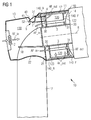
- Fig. 1 shows a first embodiment of an airflow control arrangement according to the invention.
- the diagram shows the interior of a direct-drive wind turbine 10, in which a generator 14 is mounted on a shaft 20.
- the generator comprises an outer rotor 11 and an inner stator 12.
- a hub and rotor blades (not shown in the diagram) are mounted to the front of the shaft 20, so that a rotation of the hub results in a rotation of the outer rotor 11 about an axis of rotation R.
- the inner stator 12 remains stationary relative to the shaft 20.
- Windings 121 (cf. Figs. 3 and 4 ) are arranged on the outer surface of the stator 12, while magnet poles 111 (cf. Figs. 3 and 4 ) are arranged on the inner surface of the rotor 11.
- a narrow air-gap 150 separates the poles 111 from the windings 121.
- the windings 121 have a certain amount of overhang at one or both ends of the stator 12. This overhang is accommodated in a generator front cavity 140_F. Installation of such a wind turbine 10 can be carried out by lifting the entire generator 14 and mounting it in place in front of a canopy 13 mounted onto a tower 17.
- the canopy 13, tower 17 and generator 14 are connected in an essentially air-tight manner by means of seals 21, 22 between canopy 13 and tower 17 and between canopy 13 and generator 14.
- the seal 21 between canopy 13 and generator 14 can be a labyrinth seal 21.
- An inflow fan 2 is used to draw air AF_in into the canopy interior 130.
- the inflow fan 2 can be powerful enough to generate an overpressure in the canopy interior 130.
- the air AF_in drawn into the canopy 13 in this manner is then compelled or forced to travel along a specific path defined by stator ducts 3 that extend from one end of the stator 12 to the other end, and by an exit duct 4 extending from the stator interior 120 and realised to expel the air to the wind turbine exterior or to re-direct the air back into the canopy interior 130.
- a stator duct 3 is mounted so that the entrance opening 30 to the stator duct 3 lies in or in front of a stator back plate 123 and its exit opening 31 lies in or in front of a stator front plate 122.
- the entrance opening 30 can be outwardly flared or conical to guide an airflow AF_in into the stator duct 3.
- the air After leaving the exit openings 31 of the stator ducts 3, the air passes into a front cavity 140_F of the generator 14.
- the suction created by the outflow fan 1 draws this air through gaps between the winding overhangs and through the air-gap between magnet poles 111 and windings 121, into the stator interior 12, and finally into the exit duct 4.
- the suction created by the outflow fan 1 also draws air from a generator rear cavity 140_R through gaps between the winding overhangs and through the air-gap between magnet poles 111 and windings 121, into the stator interior 12, and then also into the exit duct 4.
- the exit duct 4 with a sufficiently large entrance opening in conjunction with a sufficiently powerful outflow fan 1 is enough to efficiently draw an airflow AF_out through the gaps between the windings 121, and also through the airgap 150 between windings 121 and magnets 111.
- the exit opening 40 of the exit duct 4 preferably arranged in an upper region of the canopy 13 in order to facilitate the expelling of air from the wind turbine.
- a mesh or grille may prevent unwanted debris from falling into the exit duct.
- the exit airflow AF_out is sucked through the outflow fan 1 and is then expelled from the wind turbine 10 and/or is returned to the canopy interior 130.
- the exit duct 4 has two exit openings, a main exit opening 40 to the wind turbine exterior, and a secondary exit opening 41 to the canopy interior.
- the amount of air expelled or returned to the interior 130 will depend on the manner in which an exit outflow arrangement 5 is set up.
- the exit outflow arrangement 5 comprises a first hatch 51 and a second hatch 52.
- the hatches 51, 52 are actuated by control signals sent from a control unit, whose functionality will be explained with the aid of Fig. 2 .
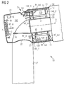
- Fig. 2 shows a second embodiment of an airflow control arrangement according to the invention.
- the exit outflow arrangement 5 comprises a three-way hatch 53 (indicated by an abstract symbol) arranged in the exit duct 4 to open and close the main exit opening 40 and the secondary exit opening 41, so that the airflow inside and out of the wind turbine can be regulated in a particularly efficient manner.
- the three-way hatch 53 can be controlled so that when the route back into the canopy interior tends to be closed, the route to the canopy exterior tends to be opened.
- This embodiment also shows a filter 7 placed in front of the inflow fan 2, so that the inflow fan 2 draws filtered air AF_in into the canopy interior.
- the filter 7 can comprise various filter layers, for example it may comprise a mist eliminator for reducing the moisture of the air that is drawn into the canopy, thus lowering the risk of damage to components inside the wind turbine.
- a control unit 6 determines how to control the three-way hatch on the basis of measurements taken by temperature sensors 60, 61 and humidity sensors 62, 63 arranged at strategic positions.
- a temperature sensor 60 measures the temperature close to the windings 121; another temperature sensor 61 measures the temperature of the ambient air entering the canopy 13; a humidity sensor 62 measures the humidity of the ambient air entering the canopy 13; and another humidity sensor 63 measures the humidity of the air being drawn into the stator interior 120.
- the control unit 6 can comprise any number of modules for analysing the information, for collecting additional information from a local or remote processing turbine controller, etc.
- Measurements from the sensors 60, 61, 62, 63 can be transmitted to the control unit 6 over a wired connection, over a wireless connection, or using any other suitable mode of communication. Similarly, the control unit 6 can transmit control signals to the hatch arrangement over any suitable connection.
- Fig. 3 shows a schematic representation of an airflow control arrangement 100 according to the invention, and the path taken by the air AF_in, AF_out as it is directed to flow through regions of the wind turbine.
- the diagram only shows the relevant components and regions.
- the inflow fan 2 draws air AF_in into the canopy interior 130.
- the outflow fan 1 sucks air into the exit duct 4.
- Various regions 130, 140_R, 140_F, 150, 120 of the wind turbine are linked to give a pre-ordained path along which the air must flow.
- the canopy interior 130 is physically separated from the stator interior 120 by the stator back plate 123.
- the air AF_in is therefore forced to pass through the ducts 3 extending from the stator backplate 123 to the stator frontplate 122, where it can flow into the generator front cavity 140_F. From here, the air is sucked by the outflow fan 1 through any gaps between the windings 121 and/or the air-gap 150 between the magnets 111 and the windings 121, so that the air is drawn into the stator interior 120. From here, the air AF_out is sucked into the exit duct.
- the rotation of the rotor 11 augments the distribution of the airflow AF_out in the air-gap 150 and gaps 160 (cf. Fig. 4 ) between the windings 121, so that the air can effectively cool the hot windings.
- the outflow fan 1 can still ensure that the airflow AF_out is effectively drawn through the air-gap 150, so that the temperature of the (initially cooler) magnets 111 can be raised, thus raising the dewpoint.
- a hatch arrangement can be controlled to re-circulate the airflow within the wind turbine, using heat dissipated by the outflow fan 1 to warm the air.
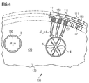
- Fig. 4 shows a view from inside the stator 12 towards the stator back plate 123, and various elements of an embodiment of an airflow control arrangement 100 according to the invention.
- air AF_in is being sucked or drawn (towards the reader) from the canopy interior 130 through a stator duct 3, which is sealed off from the stator interior cavity 120.
- the suction force is generated by the outflow fan 1 arranged in the exit duct 4 (away from the reader). Once the air has entered the generator front cavity (not shown here), it is sucked by the outflow fan 1 through the air-gap 150 between magnets 111 and windings 121, and through any gaps 160 between adjacent windings 121.
- a known winding arrangement is shown, with windings 121 separated by spacers 122.
- a narrow gap 160 is left between each spacer 122 and winding.
- the air is forced to pass through this narrow gap 160.
- the airflow is also sucked in from the canopy interior via a generator rear cavity (behind the stator back plate 123) and then through the air-gap 150 between magnets 111 and windings 121, and through any gaps 160 between adjacent windings 121.
Priority Applications (18)
| Application Number | Priority Date | Filing Date | Title |
|---|---|---|---|
| DK13168761.8T DK2806542T3 (en) | 2013-05-22 | 2013-05-22 | Airflow Control Device |
| EP13168761.8A EP2806542B1 (en) | 2013-05-22 | 2013-05-22 | Airflow control arrangement |
| CN201380076772.7A CN105210273B (zh) | 2013-05-22 | 2013-09-12 | 冷却系统 |
| EP13763034.9A EP2976829B1 (en) | 2013-05-22 | 2013-09-12 | Cooling system |
| PCT/EP2013/068943 WO2014187507A1 (en) | 2013-05-22 | 2013-09-12 | Cooling system |
| US14/888,499 US20160084226A1 (en) | 2013-05-22 | 2013-09-12 | Cooling system |
| EP14152491.8A EP2806543A1 (en) | 2013-05-22 | 2014-01-24 | Airflow control arrangement |
| PCT/EP2014/052468 WO2014187577A1 (en) | 2013-05-22 | 2014-02-07 | Ventilation device and ventilation system for a wind turbine |
| EP14705087.6A EP2981714B1 (en) | 2013-05-22 | 2014-02-07 | Ventilation device and ventilation system for a wind turbine |
| DK14705087.6T DK2981714T3 (da) | 2013-05-22 | 2014-02-07 | Ventilationsindretning og ventilationssystem til en vindmølle |
| CN201480029384.8A CN105229301A (zh) | 2013-05-22 | 2014-02-07 | 用于风力涡轮机的通风装置和通风系统 |
| IN953DE2014 IN2014DE00953A (ko) | 2013-05-22 | 2014-04-01 | |
| US14/253,893 US9624908B2 (en) | 2013-05-22 | 2014-04-16 | Airflow control arrangement |
| DE102014208791.0A DE102014208791A1 (de) | 2013-05-22 | 2014-05-09 | Luftstrom-Steueranordnung |
| BRBR102014012259-1A BR102014012259A2 (pt) | 2013-05-22 | 2014-05-21 | Disposição de controle de fluxo de ar, turbina eólica acionada de forma direta com um gerador e método de controle de um fluxo de ar |
| KR1020140061667A KR102175644B1 (ko) | 2013-05-22 | 2014-05-22 | 기류 제어 배열체 |
| JP2014105979A JP6478485B2 (ja) | 2013-05-22 | 2014-05-22 | 空気流制御装置 |
| CN201410217585.2A CN104179641B (zh) | 2013-05-22 | 2014-05-22 | 具有空气流控制布置的风力涡轮机及其空气流的控制方法 |
Applications Claiming Priority (1)
| Application Number | Priority Date | Filing Date | Title |
|---|---|---|---|
| EP13168761.8A EP2806542B1 (en) | 2013-05-22 | 2013-05-22 | Airflow control arrangement |
Publications (2)
| Publication Number | Publication Date |
|---|---|
| EP2806542A1 EP2806542A1 (en) | 2014-11-26 |
| EP2806542B1 true EP2806542B1 (en) | 2016-09-14 |
Family
ID=48534171
Family Applications (4)
| Application Number | Title | Priority Date | Filing Date |
|---|---|---|---|
| EP13168761.8A Active EP2806542B1 (en) | 2013-05-22 | 2013-05-22 | Airflow control arrangement |
| EP13763034.9A Active EP2976829B1 (en) | 2013-05-22 | 2013-09-12 | Cooling system |
| EP14152491.8A Withdrawn EP2806543A1 (en) | 2013-05-22 | 2014-01-24 | Airflow control arrangement |
| EP14705087.6A Active EP2981714B1 (en) | 2013-05-22 | 2014-02-07 | Ventilation device and ventilation system for a wind turbine |
Family Applications After (3)
| Application Number | Title | Priority Date | Filing Date |
|---|---|---|---|
| EP13763034.9A Active EP2976829B1 (en) | 2013-05-22 | 2013-09-12 | Cooling system |
| EP14152491.8A Withdrawn EP2806543A1 (en) | 2013-05-22 | 2014-01-24 | Airflow control arrangement |
| EP14705087.6A Active EP2981714B1 (en) | 2013-05-22 | 2014-02-07 | Ventilation device and ventilation system for a wind turbine |
Country Status (10)
| Country | Link |
|---|---|
| US (2) | US20160084226A1 (ko) |
| EP (4) | EP2806542B1 (ko) |
| JP (1) | JP6478485B2 (ko) |
| KR (1) | KR102175644B1 (ko) |
| CN (3) | CN105210273B (ko) |
| BR (1) | BR102014012259A2 (ko) |
| DE (1) | DE102014208791A1 (ko) |
| DK (2) | DK2806542T3 (ko) |
| IN (1) | IN2014DE00953A (ko) |
| WO (2) | WO2014187507A1 (ko) |
Families Citing this family (57)
| Publication number | Priority date | Publication date | Assignee | Title |
|---|---|---|---|---|
| DK2795108T3 (en) * | 2011-12-21 | 2018-06-25 | Wobben Properties Gmbh | Wind turbine Nacelle |
| DK2662952T3 (en) * | 2012-05-11 | 2015-09-14 | Siemens Ag | Generator, especially for a wind turbine |
| US9528498B2 (en) * | 2012-09-13 | 2016-12-27 | Jaime Miguel Bardia | On or off grid vertical axis wind turbine and self contained rapid deployment autonoous battlefield robot recharging and forward operating base horizontal axis wind turbine |
| EP2806542B1 (en) * | 2013-05-22 | 2016-09-14 | Siemens Aktiengesellschaft | Airflow control arrangement |
| EP2902619B1 (en) * | 2014-01-29 | 2018-01-17 | Siemens Aktiengesellschaft | Cooling arrangement for a direct drive wind turbine |
| DK2937562T3 (en) | 2014-04-25 | 2017-10-16 | Siemens Ag | Device for attenuating acoustic noise caused by air cooling of at least one wind turbine component provided with the nacelle of a wind turbine |
| CN104600886B (zh) * | 2015-01-27 | 2017-01-25 | 新疆金风科技股份有限公司 | 永磁直驱风力发电机、系统及其定子 |
| EP3054565A1 (en) * | 2015-02-06 | 2016-08-10 | Siemens Aktiengesellschaft | Cooling arrangement |
| CN104810942B (zh) * | 2015-04-15 | 2017-03-01 | 新疆金风科技股份有限公司 | 永磁直驱风力发电机、系统及其定子 |
| CN104810997B (zh) * | 2015-04-15 | 2017-03-01 | 新疆金风科技股份有限公司 | 永磁直驱风力发电机系统及其密封协同干燥控制方法 |
| FR3042327B1 (fr) * | 2015-10-07 | 2019-08-02 | Guillemot Corporation | Systeme de refroidissement d'un moteur electrique |
| DE102015015338A1 (de) * | 2015-11-26 | 2017-06-01 | Munters Euroform Gmbh | Windkraftanlage, Gondel und Kühleinrichtung für eine Windkraftanlage |
| DE102015122855A1 (de) * | 2015-12-28 | 2017-06-29 | Wobben Properties Gmbh | Windenergieanlage und Kühlvorrichtung für eine Windenergieanlage |
| CN105736258B (zh) * | 2016-03-02 | 2019-05-03 | 新疆金风科技股份有限公司 | 一种流体输运装置及多相流分离装置 |
| CN105553182B (zh) * | 2016-03-02 | 2018-09-14 | 新疆金风科技股份有限公司 | 一种风力发电机系统及流体输运装置 |
| GB2558171A (en) * | 2016-03-18 | 2018-07-11 | Cummins Generator Technologies | Adaptor with improved airflow |
| CN106014882A (zh) * | 2016-06-03 | 2016-10-12 | 国电联合动力技术有限公司 | 一种风电机组的冷却方法及冷却系统 |
| DE102016111332B3 (de) * | 2016-06-21 | 2017-06-29 | Aerodyn Engineering Gmbh | Modular aufgebaute Windenergieanlage |
| EP3270491A1 (en) * | 2016-07-15 | 2018-01-17 | Siemens Aktiengesellschaft | Cooling arrangement of a wind turbine generator |
| EP3273578B1 (en) * | 2016-07-21 | 2020-06-03 | Siemens Aktiengesellschaft | Cooling arrangement of a wind turbine generator |
| DK3279469T3 (da) | 2016-08-05 | 2020-05-25 | Siemens Gamesa Renewable Energy As | Vindmølle med forbedret køling af generatoren og fremgangsmåde til køling af generatoren af en vindmølle |
| US20180038351A1 (en) * | 2016-08-05 | 2018-02-08 | Siemens Aktiengesellschaft | Wind turbine with improved cooling |
| CN106121940A (zh) * | 2016-08-25 | 2016-11-16 | 优利康达(天津)科技有限公司 | 风电机舱温度调节系统 |
| CN106089603A (zh) * | 2016-08-25 | 2016-11-09 | 优利康达(天津)科技有限公司 | 风电机舱通风装置 |
| CN109642553B (zh) * | 2016-09-30 | 2021-02-05 | 弗兰德有限公司 | 冷却安装在风力涡轮机的机舱中的发电机的装置及方法 |
| DE102016125218A1 (de) | 2016-12-21 | 2018-06-21 | Wobben Properties Gmbh | Statorträger für einen Stator eines Windenergieanlagengenerators, sowie Stator, Generator und Windenergieanlage mit selbigem |
| DE102017100134A1 (de) * | 2017-01-05 | 2018-07-05 | Wobben Properties Gmbh | Windenergieanlage und Verwendung eines Tropfenabscheiders in einem Windenergieanlagenrotor |
| EP3560080A1 (en) * | 2017-02-02 | 2019-10-30 | Siemens Gamesa Renewable Energy A/S | Cooling arrangement |
| JP6474441B2 (ja) * | 2017-03-10 | 2019-02-27 | ファナック株式会社 | 電動機及び工作機械 |
| CN106894955B (zh) * | 2017-03-13 | 2019-01-04 | 新疆金风科技股份有限公司 | 风力发电机组的机舱风冷降温系统及风力发电机组 |
| EP3382199B1 (en) * | 2017-03-27 | 2023-12-20 | Siemens Gamesa Renewable Energy A/S | Nacelle for a wind turbine including a cooling circuit |
| DE102017107897A1 (de) * | 2017-04-12 | 2018-10-18 | Wobben Properties Gmbh | Verfahren zum Kühlen einer getriebelosen Windenergieanlage |
| CN107605666B (zh) * | 2017-09-11 | 2019-01-11 | 北京金风科创风电设备有限公司 | 具有抑制涡激振动功能的围护结构及抑制涡激振动的方法 |
| EP3477101B1 (en) * | 2017-10-25 | 2020-06-03 | Siemens Gamesa Renewable Energy A/S | Wind turbine with a nacelle including a water draining device |
| EP3482815B1 (en) | 2017-11-08 | 2020-06-17 | Siemens Gamesa Renewable Energy A/S | Operating a wind turbine generator cooling system |
| CN108019324B (zh) | 2017-12-06 | 2019-07-09 | 北京金风科创风电设备有限公司 | 轴系的冷却系统及其控制方法以及风力发电机组 |
| EP3508720B1 (en) * | 2018-01-09 | 2020-06-17 | Siemens Gamesa Renewable Energy A/S | Wind turbine including a cooling circuit |
| EP3527820B1 (en) * | 2018-02-20 | 2020-10-07 | Siemens Gamesa Renewable Energy A/S | Wind turbine cooling arrangement |
| CN108843524B (zh) * | 2018-06-22 | 2020-04-10 | 北京金风科创风电设备有限公司 | 用于风力发电机组的散热系统及风力发电机组 |
| CN109120104B (zh) | 2018-09-28 | 2020-05-08 | 北京金风科创风电设备有限公司 | 风力发电机组、电机、电机气隙的气流输送装置 |
| CN109667732B (zh) * | 2019-02-20 | 2020-08-04 | 浙江大学 | 风力发电机组 |
| EP3719313A1 (en) * | 2019-04-05 | 2020-10-07 | Siemens Gamesa Renewable Energy A/S | Cooling arrangement for a wind turbine |
| DE102019117893B4 (de) * | 2019-07-03 | 2021-10-07 | Dr. Ing. H.C. F. Porsche Aktiengesellschaft | Antriebsstrang für ein Kraftfahrzeug mit einer direktgekühlten elektrischen Maschine und einem Getriebe, Kraftfahrzeug |
| CN110318958B (zh) * | 2019-07-17 | 2022-02-08 | 上海电气风电集团股份有限公司 | 直驱发电机主轴承机构的冷却系统及直驱发电机 |
| KR102390066B1 (ko) * | 2020-09-21 | 2022-04-25 | 유니슨 주식회사 | 풍력터빈용 발전기 |
| DE102021101937A1 (de) * | 2021-01-28 | 2022-07-28 | Rolls-Royce Deutschland Ltd & Co Kg | Elektrische Maschine und Verfahren zur Reinigung eines Luftspalts in einer elektrischen Maschine |
| CN112922796B (zh) * | 2021-03-02 | 2021-11-30 | 中国华能集团清洁能源技术研究院有限公司 | 一种用于风力发电机组的冷却装置 |
| EP4064555A1 (de) | 2021-03-25 | 2022-09-28 | Wobben Properties GmbH | Windenergieanlage und verfahren zum steuern einer windenergieanlage |
| EP4083413B1 (en) * | 2021-04-28 | 2024-05-15 | General Electric Renovables España S.L. | Back-up power supply for wind turbines |
| EP4125189A1 (en) * | 2021-07-27 | 2023-02-01 | General Electric Renovables España S.L. | Cooling of active elements of electrical machines |
| CN113898542B (zh) * | 2021-09-27 | 2023-04-07 | 国网浙江省电力有限公司磐安县供电公司 | 用于风电发电机的散热装置 |
| EP4160009A1 (en) * | 2021-10-01 | 2023-04-05 | Siemens Gamesa Renewable Energy A/S | Method of controlling a wind turbine |
| EP4167447A1 (de) * | 2021-10-15 | 2023-04-19 | Wobben Properties GmbH | Generator und windenergieanlage |
| EP4167449A1 (de) * | 2021-10-15 | 2023-04-19 | Wobben Properties GmbH | Generator und windenergieanlage |
| EP4167448A1 (de) * | 2021-10-15 | 2023-04-19 | Wobben Properties GmbH | Generator und windenergieanlage |
| EP4234929A1 (en) * | 2022-02-25 | 2023-08-30 | Siemens Gamesa Renewable Energy A/S | Method of controlling a wind turbine |
| US11829214B2 (en) * | 2022-04-06 | 2023-11-28 | Microsoft Technology Licensing, Llc | Device cooling |
Family Cites Families (38)
| Publication number | Priority date | Publication date | Assignee | Title |
|---|---|---|---|---|
| JPS5714105B2 (ko) * | 1973-04-09 | 1982-03-23 | ||
| JPS5865977A (ja) * | 1981-10-14 | 1983-04-19 | Hitachi Ltd | 風力発電装置の冷却機構 |
| JP3715238B2 (ja) * | 1999-07-14 | 2005-11-09 | アロイス・ヴォベン | 閉冷却回路を有する風力利用設備 |
| FI108962B (fi) * | 1999-08-20 | 2002-04-30 | Nokia Corp | Laitekaapin jäähdytysjärjestelmä |
| NL1013129C2 (nl) | 1999-09-24 | 2001-03-27 | Lagerwey Windturbine B V | Windmolen. |
| US6882068B2 (en) * | 2002-10-08 | 2005-04-19 | General Electric Company | Forced air stator ventilation system and stator ventilation method for superconducting synchronous machine |
| JP2004301094A (ja) * | 2003-03-31 | 2004-10-28 | Ebara Corp | 風力発電装置 |
| US20050092384A1 (en) * | 2003-10-29 | 2005-05-05 | Superior Air Ducts | Semi-flexible air duct |
| DE102004014876B4 (de) * | 2004-03-22 | 2010-06-10 | Mdexx Gmbh | Ventilatorummantelung, Ventilator mit einer Ventilatorummantelung und Windenergieanlage mit einem Ventilator |
| DE102004018758A1 (de) * | 2004-04-16 | 2005-11-03 | Klinger, Friedrich, Prof. Dr.-Ing. | Turmkopf einer Windenergieanlage |
| DE102004064007B4 (de) * | 2004-09-24 | 2009-08-20 | Aloys Wobben | Windenergieanlage mit einer Generatorkühlung |
| JP2007002773A (ja) * | 2005-06-24 | 2007-01-11 | Fuji Heavy Ind Ltd | 水平軸風車 |
| DE202006009355U1 (de) * | 2006-06-13 | 2006-09-07 | Pfannenberg Gmbh | Filterlüfter mit einer Schnellbefestigungseinrichtung |
| EP2123139B1 (en) * | 2007-02-14 | 2010-08-04 | Vestas Wind Systems A/S | A system for recirculation of air in a component of a wind turbine |
| JP4994944B2 (ja) * | 2007-05-18 | 2012-08-08 | 三菱重工業株式会社 | 風力発電装置 |
| JP4796039B2 (ja) * | 2007-11-22 | 2011-10-19 | 三菱重工業株式会社 | 風力発電装置 |
| ITMI20081122A1 (it) * | 2008-06-19 | 2009-12-20 | Rolic Invest Sarl | Generatore eolico provvisto di un impianto di raffreddamento |
| JP5123780B2 (ja) * | 2008-07-28 | 2013-01-23 | 三菱重工業株式会社 | 風力発電装置 |
| WO2010022724A2 (en) * | 2008-08-28 | 2010-03-04 | Vestas Wind Systems A/S | Filtering of debris in wind turbines |
| KR101021333B1 (ko) * | 2008-09-01 | 2011-03-14 | 두산중공업 주식회사 | 풍력터빈의 나셀 냉각 시스템 |
| US8047774B2 (en) | 2008-09-11 | 2011-11-01 | General Electric Company | System for heating and cooling wind turbine components |
| DK2182618T3 (da) * | 2008-10-28 | 2012-10-29 | Siemens Ag | Anordning til afkøling af en elektrisk maskine |
| US7843080B2 (en) * | 2009-05-11 | 2010-11-30 | General Electric Company | Cooling system and wind turbine incorporating same |
| ES2377696B1 (es) * | 2009-07-06 | 2013-02-14 | Gamesa Innovation & Technology S.L. | Sistema de aportación de aire filtrado al interior de un aerogenerador. |
| US8360715B2 (en) * | 2009-07-09 | 2013-01-29 | Mitsubishi Heavy Industries, Ltd. | Wind turbine generator |
| US20110204652A1 (en) * | 2009-08-18 | 2011-08-25 | Mitsubishi Heavy Industries, Ltd. | Wind power generator |
| JP5455508B2 (ja) | 2009-08-28 | 2014-03-26 | 三菱重工業株式会社 | 風力発電用風車 |
| CN102577044B (zh) * | 2009-10-21 | 2015-04-29 | 西门子公司 | 发电机 |
| JP5072994B2 (ja) * | 2010-03-17 | 2012-11-14 | 三菱重工業株式会社 | 風力発電装置 |
| JP5511549B2 (ja) * | 2010-06-30 | 2014-06-04 | 三菱重工業株式会社 | 風力発電装置 |
| DE102010043435A1 (de) | 2010-11-04 | 2012-05-10 | Aloys Wobben | Windenergieanlage |
| DK2466128T4 (en) * | 2010-12-20 | 2017-10-02 | Siemens Ag | Wind turbine and method for controlling a wind turbine |
| ITMI20110376A1 (it) * | 2011-03-10 | 2012-09-11 | Wilic Sarl | Aerogeneratore raffreddato a fluido |
| CN202096855U (zh) * | 2011-05-25 | 2012-01-04 | 国电联合动力技术有限公司 | 一种海上或近海风力发电机机舱盐雾过滤通风装置 |
| EP2546515B1 (en) * | 2011-07-14 | 2013-09-18 | Siemens Aktiengesellschaft | Wind turbine cooling arrangement |
| FI123727B (fi) * | 2011-09-01 | 2013-10-15 | Abb Oy | Järjestely ja menetelmä sähkökoneen jäähdyttämiseksi |
| CN102748244A (zh) * | 2012-07-13 | 2012-10-24 | 国电联合动力技术有限公司 | 一种海上用风力发电机组通风过滤换热装置及方法 |
| EP2806542B1 (en) * | 2013-05-22 | 2016-09-14 | Siemens Aktiengesellschaft | Airflow control arrangement |
-
2013
- 2013-05-22 EP EP13168761.8A patent/EP2806542B1/en active Active
- 2013-05-22 DK DK13168761.8T patent/DK2806542T3/en active
- 2013-09-12 EP EP13763034.9A patent/EP2976829B1/en active Active
- 2013-09-12 WO PCT/EP2013/068943 patent/WO2014187507A1/en active Application Filing
- 2013-09-12 CN CN201380076772.7A patent/CN105210273B/zh active Active
- 2013-09-12 US US14/888,499 patent/US20160084226A1/en not_active Abandoned
-
2014
- 2014-01-24 EP EP14152491.8A patent/EP2806543A1/en not_active Withdrawn
- 2014-02-07 DK DK14705087.6T patent/DK2981714T3/da active
- 2014-02-07 EP EP14705087.6A patent/EP2981714B1/en active Active
- 2014-02-07 CN CN201480029384.8A patent/CN105229301A/zh active Pending
- 2014-02-07 WO PCT/EP2014/052468 patent/WO2014187577A1/en active Application Filing
- 2014-04-01 IN IN953DE2014 patent/IN2014DE00953A/en unknown
- 2014-04-16 US US14/253,893 patent/US9624908B2/en active Active
- 2014-05-09 DE DE102014208791.0A patent/DE102014208791A1/de not_active Withdrawn
- 2014-05-21 BR BRBR102014012259-1A patent/BR102014012259A2/pt not_active IP Right Cessation
- 2014-05-22 CN CN201410217585.2A patent/CN104179641B/zh active Active
- 2014-05-22 KR KR1020140061667A patent/KR102175644B1/ko active IP Right Grant
- 2014-05-22 JP JP2014105979A patent/JP6478485B2/ja active Active
Also Published As
| Publication number | Publication date |
|---|---|
| KR20140138062A (ko) | 2014-12-03 |
| CN105210273B (zh) | 2019-07-09 |
| US9624908B2 (en) | 2017-04-18 |
| DK2806542T3 (en) | 2016-12-19 |
| JP6478485B2 (ja) | 2019-03-06 |
| DE102014208791A1 (de) | 2014-11-27 |
| EP2806542A1 (en) | 2014-11-26 |
| BR102014012259A2 (pt) | 2015-05-26 |
| EP2976829B1 (en) | 2017-01-18 |
| EP2806543A1 (en) | 2014-11-26 |
| EP2981714A1 (en) | 2016-02-10 |
| CN105210273A (zh) | 2015-12-30 |
| WO2014187507A1 (en) | 2014-11-27 |
| CN104179641B (zh) | 2019-08-06 |
| DK2981714T3 (da) | 2020-06-02 |
| CN105229301A (zh) | 2016-01-06 |
| US20160084226A1 (en) | 2016-03-24 |
| CN104179641A (zh) | 2014-12-03 |
| EP2981714B1 (en) | 2020-04-01 |
| IN2014DE00953A (ko) | 2015-06-05 |
| EP2976829A1 (en) | 2016-01-27 |
| US20140346781A1 (en) | 2014-11-27 |
| JP2014230487A (ja) | 2014-12-08 |
| WO2014187577A1 (en) | 2014-11-27 |
| KR102175644B1 (ko) | 2020-11-09 |
Similar Documents
| Publication | Publication Date | Title |
|---|---|---|
| EP2806542B1 (en) | Airflow control arrangement | |
| DK2958217T3 (en) | Generator Cooling Device | |
| CN102245897B (zh) | 包括冷却回路的风力涡轮机 | |
| EP3485163B1 (en) | Cooling a wind turbine generator | |
| EP3527820B1 (en) | Wind turbine cooling arrangement | |
| EP2136077A2 (en) | Wind power plant equipped with generator cooling system | |
| EP3054569A1 (en) | Cooling arrangement | |
| US20180038351A1 (en) | Wind turbine with improved cooling | |
| EP3054565A1 (en) | Cooling arrangement | |
| EP2546515B1 (en) | Wind turbine cooling arrangement | |
| EP2902619B1 (en) | Cooling arrangement for a direct drive wind turbine | |
| EP2639450B1 (en) | Air conditioning system for a wind turbine and method for ventilating and pressurizing a wind turbine | |
| JP6650318B2 (ja) | 風力発電装置 | |
| EP3719313A1 (en) | Cooling arrangement for a wind turbine | |
| EP3270491A1 (en) | Cooling arrangement of a wind turbine generator | |
| EP3273578B1 (en) | Cooling arrangement of a wind turbine generator | |
| EP2587052A1 (en) | Wind turbine with cooling system | |
| US8502407B2 (en) | Wind power generating apparatus | |
| KR20150145608A (ko) | 풍력발전기용 나셀의 제설 장치 |
Legal Events
| Date | Code | Title | Description |
|---|---|---|---|
| PUAI | Public reference made under article 153(3) epc to a published international application that has entered the european phase |
Free format text: ORIGINAL CODE: 0009012 |
|
| 17P | Request for examination filed |
Effective date: 20130522 |
|
| AK | Designated contracting states |
Kind code of ref document: A1 Designated state(s): AL AT BE BG CH CY CZ DE DK EE ES FI FR GB GR HR HU IE IS IT LI LT LU LV MC MK MT NL NO PL PT RO RS SE SI SK SM TR |
|
| AX | Request for extension of the european patent |
Extension state: BA ME |
|
| R17P | Request for examination filed (corrected) |
Effective date: 20141106 |
|
| RBV | Designated contracting states (corrected) |
Designated state(s): AL AT BE BG CH CY CZ DE DK EE ES FI FR GB GR HR HU IE IS IT LI LT LU LV MC MK MT NL NO PL PT RO RS SE SI SK SM TR |
|
| 17Q | First examination report despatched |
Effective date: 20150930 |
|
| RIC1 | Information provided on ipc code assigned before grant |
Ipc: F03D 9/00 20160101ALN20160208BHEP Ipc: H02K 9/04 20060101ALI20160208BHEP Ipc: H02K 7/18 20060101AFI20160208BHEP |
|
| GRAP | Despatch of communication of intention to grant a patent |
Free format text: ORIGINAL CODE: EPIDOSNIGR1 |
|
| INTG | Intention to grant announced |
Effective date: 20160406 |
|
| GRAS | Grant fee paid |
Free format text: ORIGINAL CODE: EPIDOSNIGR3 |
|
| GRAA | (expected) grant |
Free format text: ORIGINAL CODE: 0009210 |
|
| AK | Designated contracting states |
Kind code of ref document: B1 Designated state(s): AL AT BE BG CH CY CZ DE DK EE ES FI FR GB GR HR HU IE IS IT LI LT LU LV MC MK MT NL NO PL PT RO RS SE SI SK SM TR |
|
| REG | Reference to a national code |
Ref country code: GB Ref legal event code: FG4D |
|
| REG | Reference to a national code |
Ref country code: CH Ref legal event code: EP |
|
| REG | Reference to a national code |
Ref country code: IE Ref legal event code: FG4D |
|
| REG | Reference to a national code |
Ref country code: AT Ref legal event code: REF Ref document number: 829957 Country of ref document: AT Kind code of ref document: T Effective date: 20161015 |
|
| REG | Reference to a national code |
Ref country code: DE Ref legal event code: R096 Ref document number: 602013011354 Country of ref document: DE |
|
| REG | Reference to a national code |
Ref country code: DK Ref legal event code: T3 Effective date: 20161215 |
|
| REG | Reference to a national code |
Ref country code: SE Ref legal event code: TRGR |
|
| REG | Reference to a national code |
Ref country code: LT Ref legal event code: MG4D |
|
| REG | Reference to a national code |
Ref country code: NL Ref legal event code: MP Effective date: 20160914 |
|
| PG25 | Lapsed in a contracting state [announced via postgrant information from national office to epo] |
Ref country code: RS Free format text: LAPSE BECAUSE OF FAILURE TO SUBMIT A TRANSLATION OF THE DESCRIPTION OR TO PAY THE FEE WITHIN THE PRESCRIBED TIME-LIMIT Effective date: 20160914 Ref country code: LT Free format text: LAPSE BECAUSE OF FAILURE TO SUBMIT A TRANSLATION OF THE DESCRIPTION OR TO PAY THE FEE WITHIN THE PRESCRIBED TIME-LIMIT Effective date: 20160914 Ref country code: HR Free format text: LAPSE BECAUSE OF FAILURE TO SUBMIT A TRANSLATION OF THE DESCRIPTION OR TO PAY THE FEE WITHIN THE PRESCRIBED TIME-LIMIT Effective date: 20160914 Ref country code: FI Free format text: LAPSE BECAUSE OF FAILURE TO SUBMIT A TRANSLATION OF THE DESCRIPTION OR TO PAY THE FEE WITHIN THE PRESCRIBED TIME-LIMIT Effective date: 20160914 Ref country code: NO Free format text: LAPSE BECAUSE OF FAILURE TO SUBMIT A TRANSLATION OF THE DESCRIPTION OR TO PAY THE FEE WITHIN THE PRESCRIBED TIME-LIMIT Effective date: 20161214 |
|
| REG | Reference to a national code |
Ref country code: AT Ref legal event code: MK05 Ref document number: 829957 Country of ref document: AT Kind code of ref document: T Effective date: 20160914 |
|
| PG25 | Lapsed in a contracting state [announced via postgrant information from national office to epo] |
Ref country code: GR Free format text: LAPSE BECAUSE OF FAILURE TO SUBMIT A TRANSLATION OF THE DESCRIPTION OR TO PAY THE FEE WITHIN THE PRESCRIBED TIME-LIMIT Effective date: 20161215 Ref country code: LV Free format text: LAPSE BECAUSE OF FAILURE TO SUBMIT A TRANSLATION OF THE DESCRIPTION OR TO PAY THE FEE WITHIN THE PRESCRIBED TIME-LIMIT Effective date: 20160914 Ref country code: NL Free format text: LAPSE BECAUSE OF FAILURE TO SUBMIT A TRANSLATION OF THE DESCRIPTION OR TO PAY THE FEE WITHIN THE PRESCRIBED TIME-LIMIT Effective date: 20160914 |
|
| PG25 | Lapsed in a contracting state [announced via postgrant information from national office to epo] |
Ref country code: EE Free format text: LAPSE BECAUSE OF FAILURE TO SUBMIT A TRANSLATION OF THE DESCRIPTION OR TO PAY THE FEE WITHIN THE PRESCRIBED TIME-LIMIT Effective date: 20160914 Ref country code: RO Free format text: LAPSE BECAUSE OF FAILURE TO SUBMIT A TRANSLATION OF THE DESCRIPTION OR TO PAY THE FEE WITHIN THE PRESCRIBED TIME-LIMIT Effective date: 20160914 |
|
| REG | Reference to a national code |
Ref country code: FR Ref legal event code: PLFP Year of fee payment: 5 |
|
| PG25 | Lapsed in a contracting state [announced via postgrant information from national office to epo] |
Ref country code: AT Free format text: LAPSE BECAUSE OF FAILURE TO SUBMIT A TRANSLATION OF THE DESCRIPTION OR TO PAY THE FEE WITHIN THE PRESCRIBED TIME-LIMIT Effective date: 20160914 Ref country code: ES Free format text: LAPSE BECAUSE OF FAILURE TO SUBMIT A TRANSLATION OF THE DESCRIPTION OR TO PAY THE FEE WITHIN THE PRESCRIBED TIME-LIMIT Effective date: 20160914 Ref country code: PT Free format text: LAPSE BECAUSE OF FAILURE TO SUBMIT A TRANSLATION OF THE DESCRIPTION OR TO PAY THE FEE WITHIN THE PRESCRIBED TIME-LIMIT Effective date: 20170116 Ref country code: SM Free format text: LAPSE BECAUSE OF FAILURE TO SUBMIT A TRANSLATION OF THE DESCRIPTION OR TO PAY THE FEE WITHIN THE PRESCRIBED TIME-LIMIT Effective date: 20160914 Ref country code: BG Free format text: LAPSE BECAUSE OF FAILURE TO SUBMIT A TRANSLATION OF THE DESCRIPTION OR TO PAY THE FEE WITHIN THE PRESCRIBED TIME-LIMIT Effective date: 20161214 Ref country code: IS Free format text: LAPSE BECAUSE OF FAILURE TO SUBMIT A TRANSLATION OF THE DESCRIPTION OR TO PAY THE FEE WITHIN THE PRESCRIBED TIME-LIMIT Effective date: 20170114 Ref country code: CZ Free format text: LAPSE BECAUSE OF FAILURE TO SUBMIT A TRANSLATION OF THE DESCRIPTION OR TO PAY THE FEE WITHIN THE PRESCRIBED TIME-LIMIT Effective date: 20160914 Ref country code: BE Free format text: LAPSE BECAUSE OF FAILURE TO SUBMIT A TRANSLATION OF THE DESCRIPTION OR TO PAY THE FEE WITHIN THE PRESCRIBED TIME-LIMIT Effective date: 20160914 Ref country code: PL Free format text: LAPSE BECAUSE OF FAILURE TO SUBMIT A TRANSLATION OF THE DESCRIPTION OR TO PAY THE FEE WITHIN THE PRESCRIBED TIME-LIMIT Effective date: 20160914 Ref country code: SK Free format text: LAPSE BECAUSE OF FAILURE TO SUBMIT A TRANSLATION OF THE DESCRIPTION OR TO PAY THE FEE WITHIN THE PRESCRIBED TIME-LIMIT Effective date: 20160914 |
|
| REG | Reference to a national code |
Ref country code: DE Ref legal event code: R097 Ref document number: 602013011354 Country of ref document: DE |
|
| PG25 | Lapsed in a contracting state [announced via postgrant information from national office to epo] |
Ref country code: IT Free format text: LAPSE BECAUSE OF FAILURE TO SUBMIT A TRANSLATION OF THE DESCRIPTION OR TO PAY THE FEE WITHIN THE PRESCRIBED TIME-LIMIT Effective date: 20160914 |
|
| PLBE | No opposition filed within time limit |
Free format text: ORIGINAL CODE: 0009261 |
|
| STAA | Information on the status of an ep patent application or granted ep patent |
Free format text: STATUS: NO OPPOSITION FILED WITHIN TIME LIMIT |
|
| 26N | No opposition filed |
Effective date: 20170615 |
|
| PG25 | Lapsed in a contracting state [announced via postgrant information from national office to epo] |
Ref country code: LU Free format text: LAPSE BECAUSE OF NON-PAYMENT OF DUE FEES Effective date: 20170531 |
|
| REG | Reference to a national code |
Ref country code: CH Ref legal event code: NV Representative=s name: SIEMENS SCHWEIZ AG, CH Ref country code: CH Ref legal event code: PCOW Free format text: NEW ADDRESS: WERNER-VON-SIEMENS-STRASSE 1, 80333 MUENCHEN (DE) |
|
| PG25 | Lapsed in a contracting state [announced via postgrant information from national office to epo] |
Ref country code: SI Free format text: LAPSE BECAUSE OF FAILURE TO SUBMIT A TRANSLATION OF THE DESCRIPTION OR TO PAY THE FEE WITHIN THE PRESCRIBED TIME-LIMIT Effective date: 20160914 |
|
| REG | Reference to a national code |
Ref country code: CH Ref legal event code: PL |
|
| PG25 | Lapsed in a contracting state [announced via postgrant information from national office to epo] |
Ref country code: MC Free format text: LAPSE BECAUSE OF FAILURE TO SUBMIT A TRANSLATION OF THE DESCRIPTION OR TO PAY THE FEE WITHIN THE PRESCRIBED TIME-LIMIT Effective date: 20160914 |
|
| REG | Reference to a national code |
Ref country code: IE Ref legal event code: MM4A |
|
| PG25 | Lapsed in a contracting state [announced via postgrant information from national office to epo] |
Ref country code: LI Free format text: LAPSE BECAUSE OF NON-PAYMENT OF DUE FEES Effective date: 20170531 Ref country code: CH Free format text: LAPSE BECAUSE OF NON-PAYMENT OF DUE FEES Effective date: 20170531 |
|
| PG25 | Lapsed in a contracting state [announced via postgrant information from national office to epo] |
Ref country code: LU Free format text: LAPSE BECAUSE OF NON-PAYMENT OF DUE FEES Effective date: 20170522 |
|
| PG25 | Lapsed in a contracting state [announced via postgrant information from national office to epo] |
Ref country code: IE Free format text: LAPSE BECAUSE OF NON-PAYMENT OF DUE FEES Effective date: 20170522 |
|
| REG | Reference to a national code |
Ref country code: FR Ref legal event code: PLFP Year of fee payment: 6 |
|
| PG25 | Lapsed in a contracting state [announced via postgrant information from national office to epo] |
Ref country code: MT Free format text: LAPSE BECAUSE OF NON-PAYMENT OF DUE FEES Effective date: 20170522 |
|
| PG25 | Lapsed in a contracting state [announced via postgrant information from national office to epo] |
Ref country code: AL Free format text: LAPSE BECAUSE OF FAILURE TO SUBMIT A TRANSLATION OF THE DESCRIPTION OR TO PAY THE FEE WITHIN THE PRESCRIBED TIME-LIMIT Effective date: 20160914 |
|
| PG25 | Lapsed in a contracting state [announced via postgrant information from national office to epo] |
Ref country code: HU Free format text: LAPSE BECAUSE OF FAILURE TO SUBMIT A TRANSLATION OF THE DESCRIPTION OR TO PAY THE FEE WITHIN THE PRESCRIBED TIME-LIMIT; INVALID AB INITIO Effective date: 20130522 |
|
| REG | Reference to a national code |
Ref country code: DE Ref legal event code: R081 Ref document number: 602013011354 Country of ref document: DE Owner name: SIEMENS GAMESA RENEWABLE ENERGY A/S, DK Free format text: FORMER OWNER: SIEMENS AKTIENGESELLSCHAFT, 80333 MUENCHEN, DE |
|
| PG25 | Lapsed in a contracting state [announced via postgrant information from national office to epo] |
Ref country code: CY Free format text: LAPSE BECAUSE OF FAILURE TO SUBMIT A TRANSLATION OF THE DESCRIPTION OR TO PAY THE FEE WITHIN THE PRESCRIBED TIME-LIMIT Effective date: 20160914 |
|
| PG25 | Lapsed in a contracting state [announced via postgrant information from national office to epo] |
Ref country code: MK Free format text: LAPSE BECAUSE OF FAILURE TO SUBMIT A TRANSLATION OF THE DESCRIPTION OR TO PAY THE FEE WITHIN THE PRESCRIBED TIME-LIMIT Effective date: 20160914 |
|
| REG | Reference to a national code |
Ref country code: GB Ref legal event code: 732E Free format text: REGISTERED BETWEEN 20191128 AND 20191204 |
|
| PG25 | Lapsed in a contracting state [announced via postgrant information from national office to epo] |
Ref country code: TR Free format text: LAPSE BECAUSE OF FAILURE TO SUBMIT A TRANSLATION OF THE DESCRIPTION OR TO PAY THE FEE WITHIN THE PRESCRIBED TIME-LIMIT Effective date: 20160914 |
|
| PGFP | Annual fee paid to national office [announced via postgrant information from national office to epo] |
Ref country code: FR Payment date: 20230517 Year of fee payment: 11 Ref country code: DK Payment date: 20230522 Year of fee payment: 11 Ref country code: DE Payment date: 20230519 Year of fee payment: 11 |
|
| PGFP | Annual fee paid to national office [announced via postgrant information from national office to epo] |
Ref country code: SE Payment date: 20230522 Year of fee payment: 11 |
|
| PGFP | Annual fee paid to national office [announced via postgrant information from national office to epo] |
Ref country code: GB Payment date: 20230522 Year of fee payment: 11 |