EP2806435A2 - Trenntransformator zur Verwendung in isoliertem Gleichstrom-zu-Gleichstrom-Schaltnetzteil - Google Patents
Trenntransformator zur Verwendung in isoliertem Gleichstrom-zu-Gleichstrom-Schaltnetzteil Download PDFInfo
- Publication number
- EP2806435A2 EP2806435A2 EP14169593.2A EP14169593A EP2806435A2 EP 2806435 A2 EP2806435 A2 EP 2806435A2 EP 14169593 A EP14169593 A EP 14169593A EP 2806435 A2 EP2806435 A2 EP 2806435A2
- Authority
- EP
- European Patent Office
- Prior art keywords
- winding
- shield
- isolated
- power supply
- switching power
- Prior art date
- Legal status (The legal status is an assumption and is not a legal conclusion. Google has not performed a legal analysis and makes no representation as to the accuracy of the status listed.)
- Withdrawn
Links
Images


Classifications
-
- H—ELECTRICITY
- H01—ELECTRIC ELEMENTS
- H01F—MAGNETS; INDUCTANCES; TRANSFORMERS; SELECTION OF MATERIALS FOR THEIR MAGNETIC PROPERTIES
- H01F27/00—Details of transformers or inductances, in general
- H01F27/34—Special means for preventing or reducing unwanted electric or magnetic effects, e.g. no-load losses, reactive currents, harmonics, oscillations, leakage fields
- H01F27/36—Electric or magnetic shields or screens
- H01F27/363—Electric or magnetic shields or screens made of electrically conductive material
-
- H—ELECTRICITY
- H01—ELECTRIC ELEMENTS
- H01F—MAGNETS; INDUCTANCES; TRANSFORMERS; SELECTION OF MATERIALS FOR THEIR MAGNETIC PROPERTIES
- H01F27/00—Details of transformers or inductances, in general
- H01F27/28—Coils; Windings; Conductive connections
- H01F27/288—Shielding
-
- H—ELECTRICITY
- H01—ELECTRIC ELEMENTS
- H01F—MAGNETS; INDUCTANCES; TRANSFORMERS; SELECTION OF MATERIALS FOR THEIR MAGNETIC PROPERTIES
- H01F27/00—Details of transformers or inductances, in general
- H01F27/34—Special means for preventing or reducing unwanted electric or magnetic effects, e.g. no-load losses, reactive currents, harmonics, oscillations, leakage fields
- H01F27/36—Electric or magnetic shields or screens
-
- H—ELECTRICITY
- H01—ELECTRIC ELEMENTS
- H01F—MAGNETS; INDUCTANCES; TRANSFORMERS; SELECTION OF MATERIALS FOR THEIR MAGNETIC PROPERTIES
- H01F27/00—Details of transformers or inductances, in general
- H01F27/28—Coils; Windings; Conductive connections
- H01F27/2823—Wires
- H01F2027/2833—Wires using coaxial cable as wire
Definitions
- This disclosure relates to enhancing isolated DC-to-DC switching power supplies by using an isolation transformer with low leakage inductance and low isolation capacitance to reduce the noise in the isolated DC-to-DC switching power supplies.
- Switching power supplies are notorious for generating electrical noise. Isolated switching power supplies, however, have added electrical noise via displacement-current across an isolation barrier of the isolated switching power supply. Normally, isolation transformers are used to provide the isolation barrier between the input and output of the switching power supply. The design of the isolation transformer, however, can greatly impact the level of electrical noise within the switching power supply.
- isolation transformers that contain electrostatic winding-shielding between primary and secondary windings.
- the goal of these transformers is to have the voltage swings of the primary winding couple only to a primary winding-shield and the voltage swings of the secondary winding couple only to a secondary winding-shield; however, the transformers currently being used still create a large amount of electrical noise across the isolation barrier.
- the separation of the primary windings and the secondary windings results in high leakage inductance in the transformer. High leakage inductance often increases the electrical noise of a switching power supply.
- a low leakage inductance transformer construction method is to wind a transformer using a bifilar winding technique in which two wires are wound next to each other at the same time. As the wire pair is repeatedly wound around a magnetic core, each turn of the wire pair couples to other turns that then lay upon previous turns. This additional coupling changes the leakage inductance and isolation capacitance. Small changes in the winding process can cause changes to these couplings. Thus the electrostatic coupling is not well controlled causing displacement current across the isolation barrier.
- the electrostatic coupling between the primary and secondary windings is only between the primary and secondary winding-shields.
- the two winding-shields voltage swings are the same and thus there is no displacement current between them.
- the voltage swings of the primary winding couple only to a primary winding-shield and the voltage swings of a secondary winding couple only to a secondary winding-shield.
- the leakage inductance should remain low as in a bifilar wound primary/secondary transformer.
- Certain embodiments of the disclosed technology include an isolation transformer for an isolated switching DC-to-DC power supply, where an electrostatic coupling between the primary and secondary windings occurs only between the primary winding-winding-shield and secondary winding-winding-shields.
- Certain embodiments include an isolated DC-to-DC switching power supply including an isolation power transformer that has a magnetic core, a first winding around the magnetic core, a first winding-shield around the magnetic core, a second winding-shield within the first winding-shield, and a second winding within the second winding-shield.
- the disclosed isolation transformers reduce the noise across the isolation barrier of the power supply.
- the coupling between the primary winding and the secondary winding is only between the first winding-shield and the second winding-shield. That is, the primary winding and the secondary winding are completely isolated from each other.
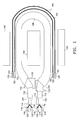
- Fig. 1 is an example of an isolation transformer 100 with two first wires 102 covered by insulation layers 104 wrapped around a magnetic core 106, acting as a first winding.
- the isolation transformer 100 also includes a double-shielded cable wrapped around the magnetic core 106.
- the first two wires are external to the double-shielded cable.
- the double-shielded cable includes an outside insulation layer 108.
- the outside insulation layer 108 encloses an outer electrostatic winding-shield 110, a first insulation layer 112, an inner electrostatic winding-shield 114, two second insulation layers 116, and two second wires 118.
- "Electrostatic winding-shield” will also be referred to as a "winding-shield" throughout the specification.
- the two second wires 118 are each covered with second insulation layers 116.
- the two second wires 118 and the second insulation layers 116 are located inside the inner winding-shield 114, which is located inside the outer winding-shield 110.
- Each of the first wires 102, second wires 118, outer winding-shield 110 and inner winding-shield 114 are soldered at soldering points 120 to a circuit board.
- the inner winding-shield 114 and the outer winding-shield 110 are composed of copper braided sheaths.
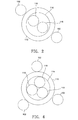
- FIG. 2 A cross-section of the layers of the double-shielded cable along with the first wires 102 external to the double-shielded cable are shown in Fig. 2 .
- the first wires 102 and the second wires 118 can both be either the primary or secondary windings of the transformer, as will be readily understood by one of ordinary skill in the art.
- the second wires 118 will be referred together as the primary winding
- the first wires 102 will be referred together as the secondary winding.
- the inner winding-shield 114 acts as the primary winding-shield
- the outer winding-shield 110 acts as the secondary winding-shield.
- the primary winding is fully encased within the primary winding-shield and the primary winding-shield is fully encased in the secondary winding-shield, there is no direct coupling between the primary winding and the secondary winding. Therefore, the voltage swing of the primary winding couples only to the primary winding-shield and the voltage swing of the secondary winding couples only to the secondary winding-shield. The capacitance between the two winding-shields is not charged or discharged. Therefore, there is no charge flow from the primary winding-shield to the secondary winding-shield.
- the center windings of the transformer of both the first wires 102 and the second wires 118 have the same voltage as the outer winding-shield 110 and the inner winding-shield 114. Due to this feature, the outer winding-shield 110, or secondary winding-shield, can be used as a center turn of the secondary winding of the transformer, and the inner winding-shield 114, or primary winding-shield, can be used as a center turn of the primary winding of the transformer.
- this embodiment includes a coaxial cable. If a coaxial cable is used, the first wires 102 would still be external to the coaxial cable. It may be desirable to use a single first wire 102 or more wires that the two first wires shows in Fig. 1 .
- the coaxial cable includes a center conductor, an inner insulation layer, an outer conductor, and an outer insulation layer. Within the coaxial cable, the center conductor would function as both the second winding-shield and the second winding. The outer conductor would function as the first winding shield.
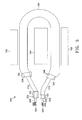
- Fig. 3 shows an embodiment similar to that of Fig. 1 .
- three first wires 102 are used in an isolation transformer 200, along with three second wires 118.
- Each of the three first wires 102 and each of the three second wires 118 has its own insulation layer 104 and 116, respectively.
- the remainder of this embodiment is the same as the embodiment discussed above with regard to Fig. 1 .
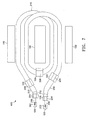
- a cross-section of the double-shielded cable of this embodiment, along with the three external first wires, is shown in Fig. 4 .
- the three second wires 118 again comprise the primary winding and the three first wires 102 comprise the secondary winding.
- Each turn of the primary winding is a second wire 118.
- the three turns of the primary winding (the three second wires 118) are completely enclosed within the inner winding-shield 114, also referred to as the primary winding-shield, and the outer winding-shield 110, also referred to as the secondary winding-shield.
- the configuration of the transformer in Fig. 3 provides that the coupling between the primary winding and the secondary winding occurs only between the primary winding-shield and the secondary winding-shield. Again, there is no direct coupling between the primary and secondary windings and the voltage swing of the primary winding couples only to the primary winding-shield and the voltage swing of the secondary winding couples only to the secondary winding-shield.
- an isolation transformer 300 is built using a single triaxial cable around the magnetic core 106.
- the triaxial cable is wound around the magnetic core 106 a single time.
- the isolation transformer 300 has two isolated secondary windings.
- the triaxial cable includes a conductor 202, a braided sheath 204, and another braided sheath 206. This configuration can be seen in the cross-section of the triaxial cable in Fig. 6 .
- each of these layers includes an insulation layer 208 and 212 between them, with a final insulation layer 210 on the outside.
- Each conductor of the triaxial cable, including conductor 202 and braided sheaths 204 and 206 can be independent windings of the transformer and winding-shields. Therefore, the isolation transformer 300, for example, can have a primary winding (conductor 202) and two secondary windings (braided sheaths 204 and 206, referred to herein as first secondary winding and second secondary winding, respectively). No wires are external to the triaxial cable in this embodiment.
- the two braided sheaths 204 and 206 still act as a primary and secondary winding-shield, respectively, as well.
- the conductor 202 could be the secondary winding and the two braided sheaths 204 and 206 could be the two primary windings.
- Both the primary winding of conductor 202 and the secondary winding of braided sheath 206 are independent due to the braided sheath 204.
- the second secondary winding, braided sheath 206 has no direct coupling to the primary winding, conductor 202.
- external wires may be provided outside the triaxial cable, providing more turns to the primary winding, similar to that shown in Figs. 1 and 3 . These external wires of the primary winding will still be shielded from the conductor 202 due to the braided sheath 206.
- a coaxial cable may be used in place of the triaxial cable.
- the inner conductor of the coaxial cable would act both as a second winding-shield and the second winding.
- the outer conductor would act as both a first winding-shield and the first winding.
- the triaxial cable shown in Fig. 5 can be wound around the magnetic core 106 two times, as shown in Fig. 7 . Therefore, each primary winding and the two secondary windings have two turns in the isolation transformer 400.
- the insulation layer 210 is removed around the braided sheath 206 in three spots.
- the braided sheath 206 acts as the primary winding and is soldered to soldering points 120 at these three spots.
- the first secondary winding (braided sheath 204) and the second secondary winding (conductor 202) are also soldered to the circuit board at soldering points 120.
- an isolation transformer is shown using two triaxial cables wound in parallel around a magnetic core.
- One triaxial cable is placed on the top of a circuit board and the other triaxial cable is placed on the bottom of the circuit board.
- the triaxial cables are referred to as the top cable and the bottom cable.
- the two cables are wound around a magnetic core 106.
- four wires are provided external to the triaxial cable.
- Two wires 302, referred to herein as the top wires are provided on the top of the circuit board, and two of the wires 304, referred to herein as the bottom wires, are provided on the bottom of the circuit board.
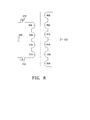
- the circuit diagram for such a configuration is shown in Fig. 8 .
- An isolation transformer 500 on a top side of the circuit board is shown in Fig. 9 .
- the isolation transformer on the bottom side of the circuit board would contain the same configuration as that shown in Fig. 9 .
- the primary winding is composed of four turns including the bottom conductor 306, the top inner winding-shield 308, the bottom inner winding-shield 310, and the top conductor 312.
- the secondary winding includes six turns comprising the second top wire 302, the first top wire 302, the top outer winding-shield 314, the bottom outer winding-shield 316, the first bottom wire 304, and the second bottom wire 304.
- the bottom conductor 306 and the top conductor 312 of the primary winding are each connected to MOSFET switches 318.
- the top inner winding-shield 308 and the bottom inner winding-shield 310 are both connected to a primary ground (earth ground) 320.
- the top outer winding-shield 314 and the bottom outer winding-shield 316 are connected to a secondary floating ground 322. Each of these components is shown in Fig. 9 . Further, soldering points 120 and insulation layers 324 are shown. In this configuration, the inner winding-shields 308 and 310 and the outer winding-shields 314 and 316 act as both a turn of the windings and winding-shields, as discussed above with respect to Fig. 4 .
- more than two transformers can be wound in parallel around the magnetic core 106.
- coaxial cables may be used in place of the triaxial cables.
- isolation transformers described above in the various embodiments, wherein the primary winding and the secondary winding have no direct coupling, have provided noise across the isolation barrier magnitudes lower than previously used isolation transformers.
- the magnetic core 106 may be ferrite for example. However, any type of magnetic core known in the art may be used.
- the braided sheaths of the triaxial cables and the double-shielded cables should be of the highest quality. If the braided sheaths are not of the highest quality, the primary winding and the secondary windings may be able to couple directly through the winding-shields and provide electrical noise. The better the quality of the braided sheaths, the less electrical noise provided through the isolation transformer.
Landscapes
- Engineering & Computer Science (AREA)
- Power Engineering (AREA)
- Regulation Of General Use Transformers (AREA)
- Dc-Dc Converters (AREA)
- Communication Cables (AREA)
- Coils Of Transformers For General Uses (AREA)
Applications Claiming Priority (1)
| Application Number | Priority Date | Filing Date | Title |
|---|---|---|---|
| US13/902,004 US9478351B2 (en) | 2013-05-24 | 2013-05-24 | Isolation transformer for use in isolated DC-to-DC switching power supply |
Publications (2)
| Publication Number | Publication Date |
|---|---|
| EP2806435A2 true EP2806435A2 (de) | 2014-11-26 |
| EP2806435A3 EP2806435A3 (de) | 2014-12-03 |
Family
ID=50771171
Family Applications (1)
| Application Number | Title | Priority Date | Filing Date |
|---|---|---|---|
| EP14169593.2A Withdrawn EP2806435A3 (de) | 2013-05-24 | 2014-05-23 | Trenntransformator zur Verwendung in isoliertem Gleichstrom-zu-Gleichstrom-Schaltnetzteil |
Country Status (4)
| Country | Link |
|---|---|
| US (1) | US9478351B2 (de) |
| EP (1) | EP2806435A3 (de) |
| JP (1) | JP2014229911A (de) |
| CN (1) | CN104183374B (de) |
Cited By (1)
| Publication number | Priority date | Publication date | Assignee | Title |
|---|---|---|---|---|
| GB2536931A (en) * | 2015-03-31 | 2016-10-05 | E2V Tech (Uk) Ltd | A transformer |
Families Citing this family (15)
| Publication number | Priority date | Publication date | Assignee | Title |
|---|---|---|---|---|
| DE102013226066A1 (de) * | 2013-12-16 | 2015-06-18 | Siemens Aktiengesellschaft | Planartransformator und elektrisches Bauteil |
| CN104617235A (zh) | 2015-02-25 | 2015-05-13 | 京东方科技集团股份有限公司 | 一种有机电致发光显示器件、其制作方法及显示装置 |
| US10049810B2 (en) * | 2015-11-09 | 2018-08-14 | Raytheon Company | High voltage high frequency transformer |
| US10903653B2 (en) | 2015-12-08 | 2021-01-26 | Smart Wires Inc. | Voltage agnostic power reactor |
| US10008317B2 (en) | 2015-12-08 | 2018-06-26 | Smart Wires Inc. | Voltage or impedance-injection method using transformers with multiple secondary windings for dynamic power flow control |
| US10180696B2 (en) | 2015-12-08 | 2019-01-15 | Smart Wires Inc. | Distributed impedance injection module for mitigation of the Ferranti effect |
| US10418814B2 (en) | 2015-12-08 | 2019-09-17 | Smart Wires Inc. | Transformers with multi-turn primary windings for dynamic power flow control |
| US10199150B2 (en) | 2015-12-10 | 2019-02-05 | Smart Wires Inc. | Power transmission tower mounted series injection transformer |
| US10218175B2 (en) | 2016-02-11 | 2019-02-26 | Smart Wires Inc. | Dynamic and integrated control of total power system using distributed impedance injection modules and actuator devices within and at the edge of the power grid |
| US10097037B2 (en) | 2016-02-11 | 2018-10-09 | Smart Wires Inc. | System and method for distributed grid control with sub-cyclic local response capability |
| GB201612032D0 (en) | 2016-07-11 | 2016-08-24 | High Speed Trans Solutions Ltd | Isolating transformer |
| US10468880B2 (en) | 2016-11-15 | 2019-11-05 | Smart Wires Inc. | Systems and methods for voltage regulation using split-conductors with loop current reduction |
| US10672553B2 (en) | 2017-05-10 | 2020-06-02 | Raytheon Company | High voltage high frequency transformer |
| US10666038B2 (en) | 2017-06-30 | 2020-05-26 | Smart Wires Inc. | Modular FACTS devices with external fault current protection |
| WO2020164085A1 (zh) * | 2019-02-15 | 2020-08-20 | 佛山市顺德区伊戈尔电力科技有限公司 | 用于变压器绕组的导线及一种变压器 |
Family Cites Families (16)
| Publication number | Priority date | Publication date | Assignee | Title |
|---|---|---|---|---|
| GB719219A (en) | 1951-04-14 | 1954-12-01 | Anderson Boyes & Co Ltd | Improvements in or relating to polyphase current transformers for use in earth leakage protective systems |
| US3314031A (en) * | 1964-02-17 | 1967-04-11 | Ite Circuit Breaker Ltd | Zero reactance transformer |
| US3717808A (en) | 1971-05-19 | 1973-02-20 | Communications Satellite Corp | Shielded coaxial cable transformer |
| US3885085A (en) * | 1974-06-11 | 1975-05-20 | Gen Cable Corp | High voltage solid extruded insulated power cables |
| JPS55154525U (de) | 1979-04-24 | 1980-11-07 | ||
| US4507721A (en) | 1982-07-28 | 1985-03-26 | Nippon Telegraph & Telephone Public Corporation | DC-DC Converter for remote power feeding |
| US5304739A (en) * | 1991-12-19 | 1994-04-19 | Klug Reja B | High energy coaxial cable for use in pulsed high energy systems |
| JPH06132145A (ja) * | 1992-02-03 | 1994-05-13 | Origin Electric Co Ltd | エックス線管用フィラメントトランス |
| US6211498B1 (en) * | 1999-03-01 | 2001-04-03 | Powell Power Electronics, Inc. | Induction heating apparatus and transformer |
| US6320385B1 (en) | 1999-09-17 | 2001-11-20 | Picker International, Inc. | Multi-channel balun for magnetic resonance apparatus |
| JP2004335886A (ja) * | 2003-05-09 | 2004-11-25 | Canon Inc | トランス集合体、それを用いた電力変換装置及び太陽光発電装置 |
| JP4300517B2 (ja) * | 2003-09-24 | 2009-07-22 | 住友電気工業株式会社 | 超電導ケーブル |
| CN2857163Y (zh) * | 2005-11-04 | 2007-01-10 | 特变电工股份有限公司 | 绕组用电缆 |
| JP5351642B2 (ja) * | 2009-02-27 | 2013-11-27 | 日立電線株式会社 | ケーブル |
| JP5219219B2 (ja) | 2009-05-19 | 2013-06-26 | ニチコン株式会社 | トランスおよび該トランスを用いたスイッチング電源装置 |
| DE102010031933B4 (de) * | 2010-07-22 | 2013-07-18 | Siemens Aktiengesellschaft | Leiterplatte mit integrierter Schirmung und Lokalspulenanordnung für Magnetresonanzanwendungen |
-
2013
- 2013-05-24 US US13/902,004 patent/US9478351B2/en active Active
-
2014
- 2014-05-23 EP EP14169593.2A patent/EP2806435A3/de not_active Withdrawn
- 2014-05-23 CN CN201410220687.XA patent/CN104183374B/zh active Active
- 2014-05-26 JP JP2014108347A patent/JP2014229911A/ja not_active Abandoned
Non-Patent Citations (1)
| Title |
|---|
| None |
Cited By (4)
| Publication number | Priority date | Publication date | Assignee | Title |
|---|---|---|---|---|
| GB2536931A (en) * | 2015-03-31 | 2016-10-05 | E2V Tech (Uk) Ltd | A transformer |
| WO2016156854A3 (en) * | 2015-03-31 | 2016-12-01 | E2V Technologies (Uk) Limited | Triaxial cable transformer |
| GB2536931B (en) * | 2015-03-31 | 2020-03-11 | Teledyne E2V Uk Ltd | A transformer |
| US10896779B2 (en) | 2015-03-31 | 2021-01-19 | Teledyne Uk Limited | Triaxial cable transformer |
Also Published As
| Publication number | Publication date |
|---|---|
| CN104183374A (zh) | 2014-12-03 |
| US20140347158A1 (en) | 2014-11-27 |
| US9478351B2 (en) | 2016-10-25 |
| EP2806435A3 (de) | 2014-12-03 |
| CN104183374B (zh) | 2018-08-14 |
| JP2014229911A (ja) | 2014-12-08 |
Similar Documents
| Publication | Publication Date | Title |
|---|---|---|
| US9478351B2 (en) | Isolation transformer for use in isolated DC-to-DC switching power supply | |
| KR20200131321A (ko) | 코일 모듈, 무선 충전 방출 장치, 수신 장치, 시스템 및 단말 | |
| JP2003234221A (ja) | 巻線構成要素によって生成される電気接地変位電流を、追加巻線を必要とすることなく実質的に小さくするための方法および装置 | |
| US8269592B1 (en) | Pulse transformer | |
| WO2020029664A1 (zh) | 线圈模组、无线充电发射装置、接收装置、系统和终端 | |
| US6975210B2 (en) | Arrangement of an inductive coupler for power line communications | |
| US20180166205A1 (en) | Transformers having screen layers to reduce common mode noise | |
| US11289260B2 (en) | Low EMI transformator and low EMI electric cable | |
| CN201622921U (zh) | 一种降低反激式变换器共模干扰的变压器及反激式变换器 | |
| JP5727561B2 (ja) | 変圧装置 | |
| JP2016208505A (ja) | 磁気部品、および、電気回路 | |
| US20160111201A1 (en) | Transformer | |
| US20140184186A1 (en) | Method for reducing interwinding capacitance current in an isolation transformer | |
| CN103956215A (zh) | 一种屏蔽电缆 | |
| KR101629890B1 (ko) | 코일 부품 및 이를 포함하는 전원공급장치 | |
| CN210927089U (zh) | 一种高压变压器隔离与滤波相结合的防雷装置 | |
| US8988168B2 (en) | Ground noise inductive filter | |
| CN102801302A (zh) | 利用电感线圈包裹屏蔽实现降噪的方法 | |
| CN100538931C (zh) | 降低传导性电磁干扰的能量转换装置及绕制方法 | |
| CN209515412U (zh) | 一种用于平板电脑适配器电源的变压器 | |
| CN105405606A (zh) | 一种改善emi的变压器 | |
| KR101237214B1 (ko) | 동축권선 탭인덕터 | |
| CN201984892U (zh) | 变频电缆 | |
| CN210142571U (zh) | 一种变压器结构 | |
| JP2016189686A (ja) | 電界共鳴型カップラ |
Legal Events
| Date | Code | Title | Description |
|---|---|---|---|
| PUAL | Search report despatched |
Free format text: ORIGINAL CODE: 0009013 |
|
| PUAI | Public reference made under article 153(3) epc to a published international application that has entered the european phase |
Free format text: ORIGINAL CODE: 0009012 |
|
| 17P | Request for examination filed |
Effective date: 20140523 |
|
| AK | Designated contracting states |
Kind code of ref document: A2 Designated state(s): AL AT BE BG CH CY CZ DE DK EE ES FI FR GB GR HR HU IE IS IT LI LT LU LV MC MK MT NL NO PL PT RO RS SE SI SK SM TR |
|
| AX | Request for extension of the european patent |
Extension state: BA ME |
|
| AK | Designated contracting states |
Kind code of ref document: A3 Designated state(s): AL AT BE BG CH CY CZ DE DK EE ES FI FR GB GR HR HU IE IS IT LI LT LU LV MC MK MT NL NO PL PT RO RS SE SI SK SM TR |
|
| AX | Request for extension of the european patent |
Extension state: BA ME |
|
| RIC1 | Information provided on ipc code assigned before grant |
Ipc: H01F 27/28 20060101AFI20141024BHEP Ipc: H02M 3/00 20060101ALI20141024BHEP |
|
| R17P | Request for examination filed (corrected) |
Effective date: 20150602 |
|
| RBV | Designated contracting states (corrected) |
Designated state(s): AL AT BE BG CH CY CZ DE DK EE ES FI FR GB GR HR HU IE IS IT LI LT LU LV MC MK MT NL NO PL PT RO RS SE SI SK SM TR |
|
| RIN1 | Information on inventor provided before grant (corrected) |
Inventor name: GIBBONS, JOHN Inventor name: GOEKE, WAYNE |
|
| STAA | Information on the status of an ep patent application or granted ep patent |
Free format text: STATUS: THE APPLICATION HAS BEEN WITHDRAWN |
|
| 18W | Application withdrawn |
Effective date: 20180604 |