EP2805146B1 - Anordnung mit integriertem monitoringelement - Google Patents
Anordnung mit integriertem monitoringelement Download PDFInfo
- Publication number
- EP2805146B1 EP2805146B1 EP12723527.3A EP12723527A EP2805146B1 EP 2805146 B1 EP2805146 B1 EP 2805146B1 EP 12723527 A EP12723527 A EP 12723527A EP 2805146 B1 EP2805146 B1 EP 2805146B1
- Authority
- EP
- European Patent Office
- Prior art keywords
- probe
- sample
- arrangement
- components
- reinforcement
- Prior art date
- Legal status (The legal status is an assumption and is not a legal conclusion. Google has not performed a legal analysis and makes no representation as to the accuracy of the status listed.)
- Active
Links
Images


Classifications
-
- G—PHYSICS
- G01—MEASURING; TESTING
- G01N—INVESTIGATING OR ANALYSING MATERIALS BY DETERMINING THEIR CHEMICAL OR PHYSICAL PROPERTIES
- G01N17/00—Investigating resistance of materials to the weather, to corrosion, or to light
- G01N17/04—Corrosion probes
- G01N17/043—Coupons
Definitions
- the present invention relates to an arrangement for use in a building, with at least two components, an integrated monitoring element and a connecting element for connecting the two components.
- Measuring devices for monitoring the influence of various substances on the corrosion of a steel reinforcement are for example out DE 102006030519A1 .
- EP2172765A1 or WO2005111575A1 known. All of these systems have built-in sensors in the concrete near the reinforcement, which detect physical or chemical changes in the reinforcement and emit electrical or electronic signals to an evaluation device located outside the construction. They are costly and expensive to maintain often expensive solutions and are especially suitable for components that must be constantly and immediately monitored after installation. Typical examples of such a need are the monitoring of the reinforcement of bridges.
- the present invention now has the task to present a measuring device, which is inexpensive to install and can be easily removed if necessary at any time, even after years and tested in the laboratory, without affecting the static strength of the object.
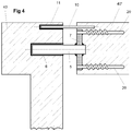
- connecting element is meant a construction with which two concrete parts 40, 40 'are connected to each other. This can be a cantilever plate connection ( FIGS. 1 to 3 ), a mandrel connection ( Fig. 4 and Fig. 6 ) or any other two concrete parts 40,40 'connecting reinforcement.
- a monitoring element of the inventive type has no supporting function. However, it is subject to the same deformations and influences as connecting rods 2 (FIG. Fig. 1 ) or spines 5 ( Fig. 4 ). But it can also be installed instead of in the same position as these elements quite simply in a force flow of a connecting element corresponding direction, where it is then exposed to the intended deformation and influences.
- a monitoring element consists of bar-like samples 10, which eg in a Kragplattenan gleichbewehrung between two connecting rods 2 of the reinforcement 20 and parallel to the same installed in about the same horizontal position ( fig1 . fig2 ) are. They are usually not equal to the representation in the sectional drawings ( Fig. 3 . 4 and 6 ) are arranged offset in their horizontal orientation to the connecting elements, but basically exposed to the same climatic and static influences, such as The parts of the reinforcement to be monitored 20. If necessary, even after several years, however, they can be removed at any time without affecting the stability of the construction. This has the advantage that they can be subjected after taking a test in the laboratory, which shows much more precise details than a rough analysis without insight into the design on site.
- the samples must have very specific dimensions.
- the cross-sectional area of the samples 10 at the critical points should not have a larger cross-sectional area than the connecting rods 2.
- the same conditions are observed for the assessment of corrosion in the area of the insulation 21 and in the area of the concrete parts 40, 40 '.
- different cross-sectional areas are selected for the samples 10 in a targeted manner from the connecting bars 2.
- a sample 10 is displaced horizontally, possibly also vertically, to the connecting rods 2 (FIG. Fig. 1 and Fig. 2 ) by simultaneous installation with the connecting rods 2 or a mandrel 5 ( Fig. 4 and Fig. 6 ) with at least a component 40,40 'frictionally installed and connected.
- a sample 10 may be arranged parallel to the connecting rods 2. In some cases, it is advisable to arrange samples 10 in a direction corresponding to the force flow of the connecting element. To observe very specific data, samples 10 may also be placed at the horizontal, vertical or both levels at an angle of 5 ° to 85 ° degrees.
- a sample 10 is usually firmly embedded in the concrete parts 40,40 '. However, it is installed as well as the connecting element.
- a cantilevered connection element Fig. 3
- the sample 10 as the observed connecting rod 2, in both concrete parts 40, 40 'firmly and non-positively anchored.
- a thorn connection Fig. 4
- the sample 10, as well as the mandrel 5 is movably disposed in its sleeve 6, movably disposed in a sleeve 11.
- the sample 10 In order to be able to remove the sample more easily and to be able to bring it to the laboratory, for example, it can be walled up non-positively in a concrete part 40, 40 ', with a short threaded stub protruding from the concrete. About this threaded stub a nut 12 is slipped, this nut 12 on the Protrudes threaded stub. In this protruding thread of the nut 12, the sample 10, which is provided for this case, of course, at the end of the same thread as the threaded stub, is screwed into the nut 12. If the sample 10 is provided with a right-hand thread at one end and a left-handed thread at the other end ( FIGS.
- the middle part 10 of the sample ( Fig. 6 ) are unscrewed. If the sample 10 has no such thread, it can be sawn out in the region of the insulation 21. In any case, the location where the sample 10 is inserted is indicated. This makes it possible even after years to remove them, even if the concrete parts 40, 40 'have to be damaged locally. Because, according to definition and design, a sample 10 does not assume a static function, this does not affect the strength of the construction.
- samples 10 can be provided with coatings, notches, welding points, etc.
- a sample may be composed of different materials.
- Coatings will provide Sample 10 to help determine how the corrosion will work. For this purpose, possibly not the entire sample but only a certain part of the same is provided with a coating. This can also be used to test what has occurred under a damaged coating of the reinforcement on corrosion.
- Notches are used to judge what happens in the area of cracks and crevices, as some types of corrosion occur preferentially at these points.
- Strain gauges with electronic monitoring or electrical connections for electrical monitoring can also be attached to such installed monitoring elements, but without violating the aforementioned patents due to their position (outside the concrete).
Landscapes
- Life Sciences & Earth Sciences (AREA)
- Biodiversity & Conservation Biology (AREA)
- Ecology (AREA)
- Environmental & Geological Engineering (AREA)
- Environmental Sciences (AREA)
- Physics & Mathematics (AREA)
- Health & Medical Sciences (AREA)
- Chemical & Material Sciences (AREA)
- Analytical Chemistry (AREA)
- Biochemistry (AREA)
- General Health & Medical Sciences (AREA)
- General Physics & Mathematics (AREA)
- Immunology (AREA)
- Pathology (AREA)
- Testing Resistance To Weather, Investigating Materials By Mechanical Methods (AREA)
Description
- Die vorliegende Erfindung betrifft eine Anordnung zum Einsatz in einem Gebäude, mit mindestens zwei Bauteilen, einem integrierten Monitoringelement und einem Verbindungselement zur Verbindung der zwei Bauteile. Messvorrichtungen zur Überwachung des Einflusses verschiedener Stoffe auf die Korrosion einer Stahlarmierung sind z.B. aus
DE 102006030519A1 ,EP2172765A1 oderWO2005111575A1 bekannt. Alle diese Systeme weisen im Beton nahe der Bewehrung eingebaute Sensoren auf, welche physikalische oder chemische Änderungen der Bewehrung erfassen und über elektrische oder elektronische Signale an eine außerhalb der Konstruktion befindliche Auswerteeinrichtung abgeben. Sie stellen bezüglich Kosten und für den Unterhalt oft aufwendige Lösungen dar und sind vor allem für Bauteile geeignet, welche nach dem Einbau ständig und unmittelbar überwacht werden müssen. Typische Beispiele eines solchen Bedarfes sind die Überwachung der Bewehrung von Brücken. - Die Nutzung von Gebäuden ist in der Regel über viele Jahrzehnte Tatsache. Für Gebäudeteile die der Witterung entzogen sind stellen sich Dauerhaftigkeitsfragen kaum. Dagegen gibt es Bauteile und Verbindungen, beispielsweise im Bereich der Gebäudehülle, deren Zustand nach einigen Jahren oder Jahrzehnten mit einfachen Mitteln abschätzbar sein sollte. Typische Beispiele dieser Art sind Kragplatten für Balkone (siehe z.B.
EP 0 822 299 ), welche bekannterweise bei älteren Gebäuden hin und wieder einbrechen. Ebenso müsste sich eine solche Vorrichtung für Dorne eignen, die der Deckenbefestigung dienen und sich in nicht geschlossenen Räumen befinden, wie z.B. inEP 0 919 672 . Da es sich um Bauteile handelt, welche die vorgesehene Nutzungsdauer unbeschadet überstehen müssen, stellt sich die Frage der Alterung der Bewehrung erst nach einigen Jahren. Wenn Verbindungsstäbe korrodieren, ist deren Festigkeit stark eingeschränkt und es kann vor Ende der vorgesehenen Nutzungsdauer zum Versagen der Befestigungselemente und damit zum Einsturz der damit befestigten Bauteile kommen. Beispiele solcher Einstürze sind leider bekannt. - Für kritische Bauteile hohen Alters werden oft Expertisen eines Baufachmanns eingeholt. Obwohl sich Wissen und Technik zur Beurteilung solcher Objekte stark verbessert haben, mangelt es doch oft am wirklichen "Einblick" in das Objekt. Mögliche Korrosionsschäden können in vielen Fällen von außen schlecht beurteilt werden. Man stützt sich auf
- Mutmassungen und tendiert aus Gründen der Haftung zu konservativen Aussagen, was der Wirtschaftlichkeit meist zuwider läuft. Kritisch ist die Situation, wenn Bauteile und Verbindungselemente Teil eines statischen Systems sind, welches bei Versagen einzelner Teile kollabieren kann.
- Investoren gehen von einem vernünftigen, optimierten Gebäudelebenszyklus aus um die investierten Mittel abzuschreiben. Sie halten sich an die Forderung, dass die Objekte als Ganzes bis zum Ablauf der geplanten Lebensdauer zuverlässig und sicher genutzt werden können. Nun gibt es aber auch Gründe, weshalb man das Ojbekt länger nutzen möchte, weil z.B. die Bausubstanz den Anforderungen noch durchaus entspricht, oder wenn die Architektur speziell ist, oder wenn man das Objekt ganz einfach bewahren möchte.
- Die vorliegende Erfindung stellt sich nunmehr die Aufgabe eine Messvorrichtung vorzustellen, welche kostengünstig einzubauen ist und bei Bedarf zu einem beliebigen Zeitpunkt, auch noch nach Jahren leicht entnommen und im Labor geprüft werden kann, ohne die statische Festigkeit des Objektes zu beeinflussen.
- Diese Aufgabe löst eine Anordnung mit den Merkmalen des Patentanspruches 1. Weitere erfindungsgemässe Merkmale gehen aus den abhängigen Ansprüchen hervor und deren Vorteile sind in der nachfolgenden Beschreibung erläutert.
- In der Zeichnung zeigt:
- Fig 1
- Anordnung von Proben in einer Kragplattenanschlussbewehrung.
- Fig 2
- Anordnung von Proben in einer Kragplattenanschlussbewehrung.
- Fig 3
- Probe zu einem Kragplattenanschluss im Schnitt.
- Fig 4
- Probe zu einem Dorn im Schnitt.
- Fig 5
- Ansicht einer Probe im Verbindungelement.
- Fig 6
- Schnitt eines Verbindungselementes
- Die Figuren stellen mögliche Ausführungsbeispiele dar, welche in der nachfolgenden Beschreibung erläutert werden.
- Unter "Verbindungselement" versteht man eine Konstruktion, mit der zwei Betonteile 40, 40' miteinander verbunden sind. Dies kann ein Kragplattenanschluss (
Fig 1 bis Fig 3 ), eine Dornverbindung (Fig 4 undFig 6 ) oder jede andere zwei Betonteile 40,40' verbindende Bewehrung sein. - Ein Monitoringelement der erfinderischen Art hat keine tragende Funktion. Es ist allerdings denselben Verformungen und Einflüssen ausgesetzt, wie Verbindungsstäbe 2 (
Fig 1 ) oder Dorne 5 (Fig 4 ). Es kann aber auch anstatt in gleicher Position wie diese Elemente ganz einfach in einer dem Kraftfluss eines Verbindungselementes entsprechender Richtung eingebaut werden, wobei es dann den vorgesehenen Verformung und Einflüssen ausgesetzt ist. - Ein Monitoringelement besteht aus Stabartigen Proben 10, welche z.B. in einer Kragplattenanschlussbewehrung zwischen zwei Verbindungsstäben 2 der Bewehrung 20 und parallel zu denselben in etwa der gleichen horizontalen Lage eingebaut (
Fig1 ,Fig2 ) sind. Sie sind in der Regel ungleich der Darstellung in den Schnittzeichungen (Fig 3 ,4 und6 ) in ihrer horizontalen Ausrichtung zu den Verbindungselementen versetzt angeordnet, aber grundsätzlich denselben klimatischen und statischen Einflüssen ausgesetzt, wie die zu überwachenden Teile der Bewehrung 20. Bei Bedarf, auch nach mehreren Jahren können Sie jedoch jederzeit ohne Einfluss auf die Stabilität der Konstruktion entfernt werden. Dies birgt den Vorteil, dass sie nach der Entnahme einer Prüfung im Labor unterzogen werden können, welche sehr viel präzisere Details aufzeigt, als eine Grobanalyse ohne Einblick in die Konstruktion vor Ort. - Um aus den geprüften Proben 10 auf die vorhandene Bewehrung Rückschlüsse ziehen zu können, müssen die Proben ganz bestimmte Dimensionen aufweisen. Insbesondere die Querschnittsfläche der Proben 10 an den kritischen Stellen sollte keine grössere Querschnittsfläche als die Verbindungsstäbe 2 aufweisen. In der Regel werden für die Beurteilung der Korrosion im Bereich der Isolation 21 und im Bereich der Betonteile 40, 40' dieselben Bedingungen eingehalten werden. Es kann jedoch sein, dass für bestimmte Dorne oder Kragplatten gezielt von den Verbindungsstäben 2 unterschiedliche Querschnittsflächen für die Proben 10 gewählt werden.
- Eine Probe 10 wird horizontal, evtl. auch vertikal versetzt zu den Verbindungsstäben 2 (
Fig 1 undFig 2 ) durch gleichzeitigen Einbau mit den Verbindungsstäben 2 oder einem Dorn 5 (Fig 4 undFig 6 ) mit mindestens einem Bauteil 40,40' kraftschlüssig eingebaut und verbunden. Eine Probe 10 kann zu den Verbindungsstäben 2 parallel angeordnet sein. In manchen Fällen empfiehlt es sich Proben 10 in einer dem Kräftefluss des Verbindungselementes entsprechenden Richtung anzuordnen. Um ganz spezielle Daten zu beobachten können Proben 10 auch zur Horizontalen, zur Vertikalen oder zu beiden Ebenen in einem Winkel von 5° bis 85° Grad angeordnet werden. - Eine Probe 10 ist in der Regel in den Betonteilen 40,40' fest einbetoniert. Sie wird jedoch wie genau so eingebaut, wie das Verbindungselement. In einem Kragplattenanschlusselement (
Fig 3 ) wird die Probe 10, wie der zu beobachtende Verbindungsstab 2, in beiden Betonteilen 40, 40' fest und kraftschlüssig verankert. In einer Dornverbindung (Fig 4 ) wird die Probe 10, genauso wie der Dorn 5 in seiner Hülse 6 beweglich angeordnet ist, in einer Hülse 11 beweglich angeordnet. - Um die Probe leichter entfernen und z.B. ins Labor bringen zu können, kann diese z.B. in einem Betonteil 40,40' kraftschlüssig eingemauert sein, wobei ein kurzer mit Gewinde versehener Stummel aus dem Beton herausragt. Über diesen Gewindestummel wird eine Mutter 12 gestülpt, wobei diese Mutter 12 über den Gewindestummel hinausragt. In dieses hinausragende Gewinde der Mutter 12 wird dann die Probe 10, welche für diesen Fall natürlich mit am Ende dem gleichen Gewinde wie der Gewindestummel versehen ist, in die Mutter 12 eingedreht. Wenn die Probe 10 am einen Ende mit einem rechtsgängigen und am andern mit einem linksgängigen Gewinde versehen ist (
Fig 5 und 6 ), welche mindestens die Länge der entsprechenden Mutter 12, 12' aufweisen, kann z.B. bei einem Kragplattensanschluss im Bereich der Isolation 21 der mittlere Teil 10 der Probe (Fig 6 ) herausgeschraubt werden. Weist die Probe 10 keine solchen Gewinde auf, kann sie im Bereich der Isolation 21 herausgesägt werden. In jedem Fall wird der Ort an dem die Probe 10 eingesetzt ist, gekennzeichnet. Dies ermöglicht auch nach Jahren das Herausnehmen derselben, auch wenn dazu die Betonteile 40, 40' lokal beschädigt werden müssen. Weil gemäss Definition und Auslegung eine Probe 10 keine statische Funktion übernimmt, wird dadurch die Festigkeit der Konstruktion trotzdem nicht beeinflusst. - Je nach Bewehrung und der vorgesehenen gewünschten Kontrolle kann es erforderlich sein, die Proben 10 speziell auszurüsten. Sie können mit Beschichtungen, Einkerbungen, Schweisspunkten etc. versehen werden. Ebenso kann eine Probe aus verschiedenen Materialien zusammengesetzt sein.
- Mit Beschichtungen wird man die Probe 10 versehen, damit man feststellen kann, wie sich die Korrosion auswirkt. Zu diesem Zweck wird evtl. nicht die ganze Probe sondern nur ein gewisser Teil derselben mit einer Beschichtung versehen. Damit kann auch geprüft werden, was sich allenfalls unter einer beschädigten Beschichtung der Bewehrung an Korrosion ereignet hat.
- Einkerbungen werden angebracht um zu beurteilen was im Bereich von Spalten und Rissen geschieht, da manche Korrosionsarten bevorzugt an diesen Stellen entstehen.
- An solchermassen eingebaute Monitoringelemente können auch Dehnmessstreifen mit elektronischer Überwachung oder elektrische Anschlüsse zur elektrischen Überwachung angebracht werden, ohne jedoch aufgrund ihrer Lage (ausserhalb des Betons) die eingangs erwähnten Patente zu verletzen.
Claims (5)
- Anordnung zum Einsatz in einem Gebäude, mit mindestens zwei Bauteilen (40, 40'), einem Monitoringelement und einem Verbindungselement zur Verbindung der zwei Bauteile (40, 40'), wobei das Verbindungselement mindestens einen Verbindungsstab (2) oder Dorn (5) aufweist und das Monitoringelement in der Weise ohne Bewehrungsfunktion in der Verbindung integriert ist, dass es jederzeit ohne Einfluss auf die Stabilität der Konstruktion entfernt werden kann, und aus mindestens einer stabartigen Probe (10) besteht, und wobei die mindestens eine Probe (10) mit mindestens einem der Bauteile (40, 40') kraftschlüssig verbunden ist und mit dem zweiten der Bauteile (40,40') ebenfalls verbunden ist.
- Anordnung gemäss Anspruch 1 ,
dadurch gekennzeichnet,
dass die Probe (10) zu mindestens einem Verbindungsstab (2) parallel angeordnet ist. - Anordnung gemäss Anspruch 1 ,
dadurch gekennzeichnet,
dass die Probe (10) in einem Winkel von 5° - 85° Grad zur Vertikalen angeordnet ist. - Anordnung gemäss Anspruch 1 ,
dadurch gekennzeichnet,
dass die Probe (10) in einem Winkel von 5° - 85° Grad zur Horizontalen angeordnet ist. - Anordnung nach Anspruch 1 ,
dadurch gekennzeichnet,
dass die Probe (10) entlang dem Kräftefluss des Verbindungselements in der Weise angeordnet ist, dass sie einer vorgesehenen Verformung ausgesetzt ist.
Applications Claiming Priority (2)
| Application Number | Priority Date | Filing Date | Title |
|---|---|---|---|
| CH00091/12A CH706052A2 (de) | 2012-01-20 | 2012-01-20 | Integriertes Monitoringelement. |
| PCT/IB2012/051663 WO2013108084A1 (de) | 2012-01-20 | 2012-04-04 | Integriertes monitoringelement |
Publications (3)
| Publication Number | Publication Date |
|---|---|
| EP2805146A1 EP2805146A1 (de) | 2014-11-26 |
| EP2805146B1 true EP2805146B1 (de) | 2017-06-14 |
| EP2805146B8 EP2805146B8 (de) | 2017-11-08 |
Family
ID=46149696
Family Applications (1)
| Application Number | Title | Priority Date | Filing Date |
|---|---|---|---|
| EP12723527.3A Active EP2805146B8 (de) | 2012-01-20 | 2012-04-04 | Anordnung mit integriertem monitoringelement |
Country Status (3)
| Country | Link |
|---|---|
| EP (1) | EP2805146B8 (de) |
| CH (1) | CH706052A2 (de) |
| WO (1) | WO2013108084A1 (de) |
Citations (5)
| Publication number | Priority date | Publication date | Assignee | Title |
|---|---|---|---|---|
| EP0822299A1 (de) * | 1996-07-30 | 1998-02-04 | Basys AG | Verbindungselement |
| DE19706510C1 (de) * | 1997-02-19 | 1998-06-10 | Peter Prof Dr Ing Schiesl | Elektrodenbaugruppe für ein Korrosionsmeßsystem zum Feststellen von Korrosion von in einem Bauteil aus einem ionenleitendem Baustoff, insbesondere Beton, eingebettetem Metall |
| EP0919672A2 (de) * | 1997-11-30 | 1999-06-02 | Basys AG | Dornverankerung einer Querkraftverbindung |
| DE19818370A1 (de) * | 1998-04-24 | 1999-10-28 | Schmidt Doehl Frank | Verfahren zur Beurteilung der Korrosionsgefährdung von in einem festen nichtmetallischen Werkstoff, insbesondere Beton, eingebetteten Metalleinlagen |
| DE202006018747U1 (de) * | 2006-12-08 | 2008-04-10 | Technische Universität Carolo-Wilhelmina Zu Braunschweig | Vorrichtung zur Zustandserfassung von stahlbewehrten Betonbauteilen |
Family Cites Families (5)
| Publication number | Priority date | Publication date | Assignee | Title |
|---|---|---|---|---|
| DE3531479A1 (de) * | 1985-09-04 | 1987-03-05 | Corrocean As | Messfuehler fuer korrosionspruefung |
| DE3834628A1 (de) * | 1988-10-11 | 1990-04-12 | Peter Dr Ing Schiessl | Korrosionsmesszelle |
| US6471906B1 (en) | 2000-07-10 | 2002-10-29 | Arteva North America S.A.R.L. | Ultra low-tension relax process and tension gate-apparatus |
| ITMI20040969A1 (it) | 2004-05-14 | 2004-08-14 | Milano Politecnico | Dispositivo di misura apparato e metodo per il monitoraggio dell'insorgenza della corrosione a carico di armature metalliche annegate nel calcestruzzo armato |
| DE202006009541U1 (de) | 2006-06-19 | 2006-10-19 | GAV GmbH Schachtabdeckungen - Entwässerungstechnik | Meßvorrichtung zur Überwachung der Korrosion einer Stahlarmierung |
-
2012
- 2012-01-20 CH CH00091/12A patent/CH706052A2/de not_active Application Discontinuation
- 2012-04-04 WO PCT/IB2012/051663 patent/WO2013108084A1/de not_active Ceased
- 2012-04-04 EP EP12723527.3A patent/EP2805146B8/de active Active
Patent Citations (5)
| Publication number | Priority date | Publication date | Assignee | Title |
|---|---|---|---|---|
| EP0822299A1 (de) * | 1996-07-30 | 1998-02-04 | Basys AG | Verbindungselement |
| DE19706510C1 (de) * | 1997-02-19 | 1998-06-10 | Peter Prof Dr Ing Schiesl | Elektrodenbaugruppe für ein Korrosionsmeßsystem zum Feststellen von Korrosion von in einem Bauteil aus einem ionenleitendem Baustoff, insbesondere Beton, eingebettetem Metall |
| EP0919672A2 (de) * | 1997-11-30 | 1999-06-02 | Basys AG | Dornverankerung einer Querkraftverbindung |
| DE19818370A1 (de) * | 1998-04-24 | 1999-10-28 | Schmidt Doehl Frank | Verfahren zur Beurteilung der Korrosionsgefährdung von in einem festen nichtmetallischen Werkstoff, insbesondere Beton, eingebetteten Metalleinlagen |
| DE202006018747U1 (de) * | 2006-12-08 | 2008-04-10 | Technische Universität Carolo-Wilhelmina Zu Braunschweig | Vorrichtung zur Zustandserfassung von stahlbewehrten Betonbauteilen |
Also Published As
| Publication number | Publication date |
|---|---|
| WO2013108084A1 (de) | 2013-07-25 |
| EP2805146A1 (de) | 2014-11-26 |
| CH706052A2 (de) | 2013-07-31 |
| EP2805146B8 (de) | 2017-11-08 |
Similar Documents
| Publication | Publication Date | Title |
|---|---|---|
| DE112021000473T5 (de) | Ermüdungsprüfgerät für stiefelförmigen Stahlsäulenfuß für Eisenbahnlärmschutzwände und dessen Ermüdungsprüfverfahren | |
| DE102009031452A1 (de) | Verfahren und Vorrichtung zur Kontrolle der Durchbiegung von Tragwerken, insbesondere Dachtragwerken, mittels eines Lasers | |
| DE102017002776A1 (de) | Verfahren zur Ermittlung der Vorspannkraft von vorgespannten Schraubverbindungen und bevorzugte Verwendung des Verfahrens | |
| EP3803305A1 (de) | Verfahren zur lastüberwachung und zur bestimmung der lebensdauer von geokunststoffbewehrten erdkörpern | |
| DE102014002260A1 (de) | Bremsenprüfstand | |
| WO2019030325A1 (de) | Verfahren zur analyse und/oder überwachung von brücken sowie entsprechendes system und verwendung des systems und/oder des verfahrens | |
| DE202006018747U1 (de) | Vorrichtung zur Zustandserfassung von stahlbewehrten Betonbauteilen | |
| EP1046894B1 (de) | Lebensdauer-Indikator für hochbeanspruchte Leichtbau-Strukturen | |
| DE102010051314B4 (de) | Vorrichtung zum Stützen und lastkonstanten Halten von Gebäudeteilen | |
| EP2805146B1 (de) | Anordnung mit integriertem monitoringelement | |
| DE102011105061B4 (de) | Einbetonierbare, verschieblich ausgebildete Kopfkonstuktion zur Verankerung von Zugelementen an zyklisch beanspruchten Bauteilen | |
| DE102017102040B4 (de) | Einrichtung zum Erfassen von Veränderungen des räumlichen Abstandes zwischen zwei stationär verankerten Messpunkten | |
| EP3252451B1 (de) | Verfahren zur festigkeitsprüfung | |
| EP3626890B1 (de) | Verfahren zur tragfähigkeitsprüfung eines fundaments | |
| EP1503201B1 (de) | Verfahren zum Prüfen von stehend verankerten Masten | |
| DE3830756A1 (de) | Vorrichtung zum befestigen eines balkens | |
| DE102013208956A1 (de) | Sensorträger und zugehörige Vorrichtung zur Füllstandsmessung | |
| DE102009017942A1 (de) | Konsolen-Vorrichtung zum Abstützen von Mauerwerk | |
| DE102007052201B3 (de) | Anordnung zur Überwachung der Funktion und des Zustands von Tragwerklagern an Bauwerken | |
| DE102009057991B4 (de) | Vorrichtung zur Messung von Biegemomenten | |
| DE202023102213U1 (de) | Anker- und Vorspannanordnung für Spannbeton | |
| EP4449325A1 (de) | Schienensystem und verfahren zu seiner prüfung | |
| DE10159966A1 (de) | Anlage zum Prüfen der Biegefestigkeit eines Mastes | |
| CH683459A5 (de) | Verfahren und Prüfelement zur Ueberprüfung des Alterungszustandes von Verankerungselementen. | |
| EP4187238A1 (de) | Anordnung und verfahren zur feuchtigkeitsmessung in bauwerken |
Legal Events
| Date | Code | Title | Description |
|---|---|---|---|
| PUAI | Public reference made under article 153(3) epc to a published international application that has entered the european phase |
Free format text: ORIGINAL CODE: 0009012 |
|
| 17P | Request for examination filed |
Effective date: 20140820 |
|
| AK | Designated contracting states |
Kind code of ref document: A1 Designated state(s): AL AT BE BG CH CY CZ DE DK EE ES FI FR GB GR HR HU IE IS IT LI LT LU LV MC MK MT NL NO PL PT RO RS SE SI SK SM TR |
|
| DAX | Request for extension of the european patent (deleted) | ||
| 17Q | First examination report despatched |
Effective date: 20150825 |
|
| GRAP | Despatch of communication of intention to grant a patent |
Free format text: ORIGINAL CODE: EPIDOSNIGR1 |
|
| STAA | Information on the status of an ep patent application or granted ep patent |
Free format text: STATUS: GRANT OF PATENT IS INTENDED |
|
| INTG | Intention to grant announced |
Effective date: 20161207 |
|
| GRAS | Grant fee paid |
Free format text: ORIGINAL CODE: EPIDOSNIGR3 |
|
| GRAA | (expected) grant |
Free format text: ORIGINAL CODE: 0009210 |
|
| STAA | Information on the status of an ep patent application or granted ep patent |
Free format text: STATUS: THE PATENT HAS BEEN GRANTED |
|
| AK | Designated contracting states |
Kind code of ref document: B1 Designated state(s): AL AT BE BG CH CY CZ DE DK EE ES FI FR GB GR HR HU IE IS IT LI LT LU LV MC MK MT NL NO PL PT RO RS SE SI SK SM TR |
|
| REG | Reference to a national code |
Ref country code: GB Ref legal event code: FG4D Free format text: NOT ENGLISH |
|
| REG | Reference to a national code |
Ref country code: CH Ref legal event code: EP Ref country code: AT Ref legal event code: REF Ref document number: 901441 Country of ref document: AT Kind code of ref document: T Effective date: 20170615 |
|
| REG | Reference to a national code |
Ref country code: IE Ref legal event code: FG4D Free format text: LANGUAGE OF EP DOCUMENT: GERMAN |
|
| REG | Reference to a national code |
Ref country code: DE Ref legal event code: R096 Ref document number: 502012010549 Country of ref document: DE |
|
| REG | Reference to a national code |
Ref country code: CH Ref legal event code: NV Representative=s name: INDUSTRIEBERATUNG MAIER AG, CH Ref country code: CH Ref legal event code: PK Free format text: BERICHTIGUNG INHABER Ref country code: CH Ref legal event code: PK Free format text: BERICHTIGUNG ERFINDER |
|
| GRAT | Correction requested after decision to grant or after decision to maintain patent in amended form |
Free format text: ORIGINAL CODE: EPIDOSNCDEC |
|
| REG | Reference to a national code |
Ref country code: NL Ref legal event code: MP Effective date: 20170614 |
|
| REG | Reference to a national code |
Ref country code: LT Ref legal event code: MG4D |
|
| PG25 | Lapsed in a contracting state [announced via postgrant information from national office to epo] |
Ref country code: FI Free format text: LAPSE BECAUSE OF FAILURE TO SUBMIT A TRANSLATION OF THE DESCRIPTION OR TO PAY THE FEE WITHIN THE PRESCRIBED TIME-LIMIT Effective date: 20170614 Ref country code: GR Free format text: LAPSE BECAUSE OF FAILURE TO SUBMIT A TRANSLATION OF THE DESCRIPTION OR TO PAY THE FEE WITHIN THE PRESCRIBED TIME-LIMIT Effective date: 20170915 Ref country code: LT Free format text: LAPSE BECAUSE OF FAILURE TO SUBMIT A TRANSLATION OF THE DESCRIPTION OR TO PAY THE FEE WITHIN THE PRESCRIBED TIME-LIMIT Effective date: 20170614 Ref country code: NO Free format text: LAPSE BECAUSE OF FAILURE TO SUBMIT A TRANSLATION OF THE DESCRIPTION OR TO PAY THE FEE WITHIN THE PRESCRIBED TIME-LIMIT Effective date: 20170914 Ref country code: HR Free format text: LAPSE BECAUSE OF FAILURE TO SUBMIT A TRANSLATION OF THE DESCRIPTION OR TO PAY THE FEE WITHIN THE PRESCRIBED TIME-LIMIT Effective date: 20170614 |
|
| RAP4 | Party data changed (patent owner data changed or rights of a patent transferred) |
Owner name: BASYS AG |
|
| RIN2 | Information on inventor provided after grant (corrected) |
Inventor name: GUTZWILLER, CLEMENT Inventor name: ROBERT, ANDRE |
|
| PG25 | Lapsed in a contracting state [announced via postgrant information from national office to epo] |
Ref country code: LV Free format text: LAPSE BECAUSE OF FAILURE TO SUBMIT A TRANSLATION OF THE DESCRIPTION OR TO PAY THE FEE WITHIN THE PRESCRIBED TIME-LIMIT Effective date: 20170614 Ref country code: BG Free format text: LAPSE BECAUSE OF FAILURE TO SUBMIT A TRANSLATION OF THE DESCRIPTION OR TO PAY THE FEE WITHIN THE PRESCRIBED TIME-LIMIT Effective date: 20170914 Ref country code: NL Free format text: LAPSE BECAUSE OF FAILURE TO SUBMIT A TRANSLATION OF THE DESCRIPTION OR TO PAY THE FEE WITHIN THE PRESCRIBED TIME-LIMIT Effective date: 20170614 Ref country code: SE Free format text: LAPSE BECAUSE OF FAILURE TO SUBMIT A TRANSLATION OF THE DESCRIPTION OR TO PAY THE FEE WITHIN THE PRESCRIBED TIME-LIMIT Effective date: 20170614 Ref country code: RS Free format text: LAPSE BECAUSE OF FAILURE TO SUBMIT A TRANSLATION OF THE DESCRIPTION OR TO PAY THE FEE WITHIN THE PRESCRIBED TIME-LIMIT Effective date: 20170614 |
|
| PG25 | Lapsed in a contracting state [announced via postgrant information from national office to epo] |
Ref country code: SK Free format text: LAPSE BECAUSE OF FAILURE TO SUBMIT A TRANSLATION OF THE DESCRIPTION OR TO PAY THE FEE WITHIN THE PRESCRIBED TIME-LIMIT Effective date: 20170614 Ref country code: CZ Free format text: LAPSE BECAUSE OF FAILURE TO SUBMIT A TRANSLATION OF THE DESCRIPTION OR TO PAY THE FEE WITHIN THE PRESCRIBED TIME-LIMIT Effective date: 20170614 Ref country code: RO Free format text: LAPSE BECAUSE OF FAILURE TO SUBMIT A TRANSLATION OF THE DESCRIPTION OR TO PAY THE FEE WITHIN THE PRESCRIBED TIME-LIMIT Effective date: 20170614 Ref country code: EE Free format text: LAPSE BECAUSE OF FAILURE TO SUBMIT A TRANSLATION OF THE DESCRIPTION OR TO PAY THE FEE WITHIN THE PRESCRIBED TIME-LIMIT Effective date: 20170614 |
|
| REG | Reference to a national code |
Ref country code: CH Ref legal event code: PFA Owner name: BASYS AG, CH Free format text: FORMER OWNER: BASYS AG, CH |
|
| PG25 | Lapsed in a contracting state [announced via postgrant information from national office to epo] |
Ref country code: IT Free format text: LAPSE BECAUSE OF FAILURE TO SUBMIT A TRANSLATION OF THE DESCRIPTION OR TO PAY THE FEE WITHIN THE PRESCRIBED TIME-LIMIT Effective date: 20170614 Ref country code: SM Free format text: LAPSE BECAUSE OF FAILURE TO SUBMIT A TRANSLATION OF THE DESCRIPTION OR TO PAY THE FEE WITHIN THE PRESCRIBED TIME-LIMIT Effective date: 20170614 Ref country code: ES Free format text: LAPSE BECAUSE OF FAILURE TO SUBMIT A TRANSLATION OF THE DESCRIPTION OR TO PAY THE FEE WITHIN THE PRESCRIBED TIME-LIMIT Effective date: 20170614 Ref country code: PL Free format text: LAPSE BECAUSE OF FAILURE TO SUBMIT A TRANSLATION OF THE DESCRIPTION OR TO PAY THE FEE WITHIN THE PRESCRIBED TIME-LIMIT Effective date: 20170614 Ref country code: IS Free format text: LAPSE BECAUSE OF FAILURE TO SUBMIT A TRANSLATION OF THE DESCRIPTION OR TO PAY THE FEE WITHIN THE PRESCRIBED TIME-LIMIT Effective date: 20171014 |
|
| REG | Reference to a national code |
Ref country code: DE Ref legal event code: R097 Ref document number: 502012010549 Country of ref document: DE |
|
| PLBE | No opposition filed within time limit |
Free format text: ORIGINAL CODE: 0009261 |
|
| STAA | Information on the status of an ep patent application or granted ep patent |
Free format text: STATUS: NO OPPOSITION FILED WITHIN TIME LIMIT |
|
| PG25 | Lapsed in a contracting state [announced via postgrant information from national office to epo] |
Ref country code: DK Free format text: LAPSE BECAUSE OF FAILURE TO SUBMIT A TRANSLATION OF THE DESCRIPTION OR TO PAY THE FEE WITHIN THE PRESCRIBED TIME-LIMIT Effective date: 20170614 |
|
| 26N | No opposition filed |
Effective date: 20180315 |
|
| PG25 | Lapsed in a contracting state [announced via postgrant information from national office to epo] |
Ref country code: SI Free format text: LAPSE BECAUSE OF FAILURE TO SUBMIT A TRANSLATION OF THE DESCRIPTION OR TO PAY THE FEE WITHIN THE PRESCRIBED TIME-LIMIT Effective date: 20170614 |
|
| PG25 | Lapsed in a contracting state [announced via postgrant information from national office to epo] |
Ref country code: MT Free format text: LAPSE BECAUSE OF FAILURE TO SUBMIT A TRANSLATION OF THE DESCRIPTION OR TO PAY THE FEE WITHIN THE PRESCRIBED TIME-LIMIT Effective date: 20170614 |
|
| REG | Reference to a national code |
Ref country code: DE Ref legal event code: R119 Ref document number: 502012010549 Country of ref document: DE |
|
| PG25 | Lapsed in a contracting state [announced via postgrant information from national office to epo] |
Ref country code: MC Free format text: LAPSE BECAUSE OF FAILURE TO SUBMIT A TRANSLATION OF THE DESCRIPTION OR TO PAY THE FEE WITHIN THE PRESCRIBED TIME-LIMIT Effective date: 20170614 |
|
| REG | Reference to a national code |
Ref country code: BE Ref legal event code: MM Effective date: 20180430 |
|
| GBPC | Gb: european patent ceased through non-payment of renewal fee |
Effective date: 20180404 |
|
| REG | Reference to a national code |
Ref country code: IE Ref legal event code: MM4A |
|
| PG25 | Lapsed in a contracting state [announced via postgrant information from national office to epo] |
Ref country code: LU Free format text: LAPSE BECAUSE OF NON-PAYMENT OF DUE FEES Effective date: 20180404 Ref country code: DE Free format text: LAPSE BECAUSE OF NON-PAYMENT OF DUE FEES Effective date: 20181101 |
|
| PG25 | Lapsed in a contracting state [announced via postgrant information from national office to epo] |
Ref country code: GB Free format text: LAPSE BECAUSE OF NON-PAYMENT OF DUE FEES Effective date: 20180404 Ref country code: BE Free format text: LAPSE BECAUSE OF NON-PAYMENT OF DUE FEES Effective date: 20180430 |
|
| PG25 | Lapsed in a contracting state [announced via postgrant information from national office to epo] |
Ref country code: FR Free format text: LAPSE BECAUSE OF NON-PAYMENT OF DUE FEES Effective date: 20180430 Ref country code: IE Free format text: LAPSE BECAUSE OF NON-PAYMENT OF DUE FEES Effective date: 20180404 |
|
| REG | Reference to a national code |
Ref country code: AT Ref legal event code: MM01 Ref document number: 901441 Country of ref document: AT Kind code of ref document: T Effective date: 20180404 |
|
| PG25 | Lapsed in a contracting state [announced via postgrant information from national office to epo] |
Ref country code: AT Free format text: LAPSE BECAUSE OF NON-PAYMENT OF DUE FEES Effective date: 20180404 |
|
| PG25 | Lapsed in a contracting state [announced via postgrant information from national office to epo] |
Ref country code: TR Free format text: LAPSE BECAUSE OF FAILURE TO SUBMIT A TRANSLATION OF THE DESCRIPTION OR TO PAY THE FEE WITHIN THE PRESCRIBED TIME-LIMIT Effective date: 20170614 |
|
| PG25 | Lapsed in a contracting state [announced via postgrant information from national office to epo] |
Ref country code: HU Free format text: LAPSE BECAUSE OF FAILURE TO SUBMIT A TRANSLATION OF THE DESCRIPTION OR TO PAY THE FEE WITHIN THE PRESCRIBED TIME-LIMIT; INVALID AB INITIO Effective date: 20120404 Ref country code: PT Free format text: LAPSE BECAUSE OF FAILURE TO SUBMIT A TRANSLATION OF THE DESCRIPTION OR TO PAY THE FEE WITHIN THE PRESCRIBED TIME-LIMIT Effective date: 20170614 |
|
| PG25 | Lapsed in a contracting state [announced via postgrant information from national office to epo] |
Ref country code: CY Free format text: LAPSE BECAUSE OF FAILURE TO SUBMIT A TRANSLATION OF THE DESCRIPTION OR TO PAY THE FEE WITHIN THE PRESCRIBED TIME-LIMIT Effective date: 20170614 Ref country code: MK Free format text: LAPSE BECAUSE OF NON-PAYMENT OF DUE FEES Effective date: 20170614 |
|
| PG25 | Lapsed in a contracting state [announced via postgrant information from national office to epo] |
Ref country code: AL Free format text: LAPSE BECAUSE OF FAILURE TO SUBMIT A TRANSLATION OF THE DESCRIPTION OR TO PAY THE FEE WITHIN THE PRESCRIBED TIME-LIMIT Effective date: 20170614 |
|
| REG | Reference to a national code |
Ref country code: CH Ref legal event code: PCAR Free format text: NEW ADDRESS: BERGLIHOEH 3, 8725 ERNETSCHWIL (CH) |
|
| PGFP | Annual fee paid to national office [announced via postgrant information from national office to epo] |
Ref country code: CH Payment date: 20250708 Year of fee payment: 14 |