EP2804299A2 - Herstellungsverfahren einer mehrphasigen synchron roteirenden elektrischen Maschine und die entsprechende Maschine - Google Patents
Herstellungsverfahren einer mehrphasigen synchron roteirenden elektrischen Maschine und die entsprechende Maschine Download PDFInfo
- Publication number
- EP2804299A2 EP2804299A2 EP14168344.1A EP14168344A EP2804299A2 EP 2804299 A2 EP2804299 A2 EP 2804299A2 EP 14168344 A EP14168344 A EP 14168344A EP 2804299 A2 EP2804299 A2 EP 2804299A2
- Authority
- EP
- European Patent Office
- Prior art keywords
- coils
- stator
- poles
- rotor
- machine according
- Prior art date
- Legal status (The legal status is an assumption and is not a legal conclusion. Google has not performed a legal analysis and makes no representation as to the accuracy of the status listed.)
- Granted
Links
Images


Classifications
-
- H—ELECTRICITY
- H02—GENERATION; CONVERSION OR DISTRIBUTION OF ELECTRIC POWER
- H02K—DYNAMO-ELECTRIC MACHINES
- H02K29/00—Motors or generators having non-mechanical commutating devices, e.g. discharge tubes or semiconductor devices
- H02K29/03—Motors or generators having non-mechanical commutating devices, e.g. discharge tubes or semiconductor devices with a magnetic circuit specially adapted for avoiding torque ripples or self-starting problems
-
- H—ELECTRICITY
- H02—GENERATION; CONVERSION OR DISTRIBUTION OF ELECTRIC POWER
- H02K—DYNAMO-ELECTRIC MACHINES
- H02K1/00—Details of the magnetic circuit
- H02K1/06—Details of the magnetic circuit characterised by the shape, form or construction
- H02K1/22—Rotating parts of the magnetic circuit
- H02K1/27—Rotor cores with permanent magnets
- H02K1/2706—Inner rotors
- H02K1/272—Inner rotors the magnetisation axis of the magnets being perpendicular to the rotor axis
- H02K1/274—Inner rotors the magnetisation axis of the magnets being perpendicular to the rotor axis the rotor consisting of two or more circumferentially positioned magnets
- H02K1/2753—Inner rotors the magnetisation axis of the magnets being perpendicular to the rotor axis the rotor consisting of two or more circumferentially positioned magnets the rotor consisting of magnets or groups of magnets arranged with alternating polarity
- H02K1/276—Magnets embedded in the magnetic core, e.g. interior permanent magnets [IPM]
- H02K1/2766—Magnets embedded in the magnetic core, e.g. interior permanent magnets [IPM] having a flux concentration effect
- H02K1/2773—Magnets embedded in the magnetic core, e.g. interior permanent magnets [IPM] having a flux concentration effect consisting of tangentially magnetized radial magnets
-
- H—ELECTRICITY
- H02—GENERATION; CONVERSION OR DISTRIBUTION OF ELECTRIC POWER
- H02K—DYNAMO-ELECTRIC MACHINES
- H02K21/00—Synchronous motors having permanent magnets; Synchronous generators having permanent magnets
- H02K21/12—Synchronous motors having permanent magnets; Synchronous generators having permanent magnets with stationary armatures and rotating magnets
- H02K21/14—Synchronous motors having permanent magnets; Synchronous generators having permanent magnets with stationary armatures and rotating magnets with magnets rotating within the armatures
- H02K21/16—Synchronous motors having permanent magnets; Synchronous generators having permanent magnets with stationary armatures and rotating magnets with magnets rotating within the armatures having annular armature cores with salient poles
-
- H—ELECTRICITY
- H02—GENERATION; CONVERSION OR DISTRIBUTION OF ELECTRIC POWER
- H02K—DYNAMO-ELECTRIC MACHINES
- H02K2213/00—Specific aspects, not otherwise provided for and not covered by codes H02K2201/00 - H02K2211/00
- H02K2213/03—Machines characterised by numerical values, ranges, mathematical expressions or similar information
-
- H—ELECTRICITY
- H02—GENERATION; CONVERSION OR DISTRIBUTION OF ELECTRIC POWER
- H02K—DYNAMO-ELECTRIC MACHINES
- H02K3/00—Details of windings
- H02K3/04—Windings characterised by the conductor shape, form or construction, e.g. with bar conductors
- H02K3/28—Layout of windings or of connections between windings
Definitions
- the present invention relates to a polyphase synchronous rotary electrical machine whose rotor comprises permanent magnets for example surface, buried, flux-concentration, radial or V-shaped magnets and / or whose rotor comprises coils for example a wound rotor especially with salient poles. More particularly, the invention relates to a rotary electric machine of this type for applications specific to motor vehicles such as alternator starters.
- a rotating electrical machine comprises a stator provided with coils and a rotor comprising a number of pairs of poles.
- the pairs of poles may comprise permanent magnets housed in recesses formed in the magnetic mass of the rotor and arranged to form a plurality of alternating north and south poles.
- the pairs of poles may comprise so-called salient poles which then comprise coils wound around radial arms of the rotor. In this case, a pole is formed by a coil.
- the number of pairs of poles arranged in this way in the rotor may vary according to the applications of the rotating machine, as well as the number of notches formed in the stator in which the windings are arranged.
- a five-phase electrical machine which comprises a first element and a second element, wherein: one of the first element and the second element is adapted to be used as a rotor and the other of the first element and the second element is designed to be used as a stator; the first element comprises a plurality of poles; and the second element comprises a plurality of teeth separated by notches, and five windings each for generating one of the five phases, each winding comprising n connected coils where n is an integer, and each coil being wound around a single coil tooth.
- SPP ratio Slots per Pole per Phase
- Anglo-Saxon acronym well known to those skilled in the art. notches by number of rotor poles by number of phases of the machine.
- the invention relates to a polyphase synchronous rotary electrical machine, comprising a rotor provided with poles rotating inside a stator having notches defining teeth around which are wound stator coils.
- the so-called SPP ratio obtained by dividing the number of notches by the number of phases of the machine and the number of rotor poles is equal to 2/7.
- the ratio is optimal so that the machine has a high electromagnetic maximum free moment which is important, a relaxation torque which is relatively low and induced current losses in the rotor which are reduced to a minimum.
- the machine has the best compromise between a maximum electromagnetic torque released, a reduced expansion torque and reduced volume losses by induced currents in the rotor.
- the number of rotor poles can be formed by magnets or coils.
- the poles can also be formed on the one hand by permanent magnets and on the other hand by salient poles as in the patent application FR 2887698 .
- the number of phases is greater than or equal to 3, for example 5 or 7 phases.
- the machine comprises five phases, and the coils are wound around each tooth of the double-layer concentric stator.
- the coils of each phase are not angularly distributed in a regular manner around the periphery of the stator.
- the coils of each phase form groups of two coils called coil pairs.
- the two coils of a pair are separated by two teeth of the stator.
- the pairs of a phase are spaced apart around the stator relative to each other by 6 teeth.
- each of the two coils of each pair is wound by rotating in the same direction around a tooth of the stator and for each phase, following the perimeter of the stator, the winding direction of the coils of a pair is opposite. in the sense of winding the coils of the previous couple.
- the two coils are connected in series with respect to one another.
- the coils of each phase form two groups of two coils called coil couples and the first pair is mounted in anti parallel with the second pair.
- the coils of each phase form two groups of two coils said pairs of coil and the two pairs are arranged head to tail relative to each other.
- the rotor is provided with fourteen poles and the stator is provided with twenty notches defining twenty teeth around which are wound for the five phases twenty concentric coils double layer.
- the poles are formed by magnets and the rotor comprises recesses of the rotor adapted to receive said magnets forming the poles.
- the ratio is such that the machine presents the best compromise for the operation of the machine between a maximum electromagnetic torque released, a small amount of current losses induced in the rotor and a reduced relaxation torque.
- the magnets form poles are arranged radially and parallel to the axis of rotation of the rotor, being arranged to present at a given axial end of the machine alternately a north pole and a south pole.
- the magnets form poles are segmented radially into three parts.
- a method of manufacturing a polyphase synchronous rotating electrical machine comprising a rotor and a stator respectively provided with poles and notches adapted to house stator coils.
- the method comprises a step of determining the number of phases of the machine, the number of notches and the number of poles to be provided for the machine and presenting the best compromise for the operation of the machine with respect to Criteria.
- a stator includes teeth and notches.
- a concentric winding according to which the winding is concentrated around the teeth taken one by one.
- This concentric winding can be single layer or double layer.
- a single-layer concentric winding it is intended to pass in a notch that son of a single coil, the coil occupying two successive slots of the stator.
- the coils are not directly next to each other, instead they are separated by a tooth around which no wire is wound.
- a coil surrounds a tooth of the stator so the number of teeth of the stator is equal to that of the number of coils. Therefore, in a notch of the stator formed between two consecutive teeth of the stator, there are always two different coils in the case of a double-layer concentric winding.
- the determination step consists in choosing from a plurality of pairs of numbers, representative of a number of coils and a number of poles associated with the machine, the optimal pair of numbers in that it presents the better compromise for the operation of the machine with respect to certain criteria.
- criteria can be both positive criteria representative of the efficiency of the machine and that one seeks to enhance, or negative criteria that one seeks to minimize.
- each ratio of SPP type associated with a pair of numbers is assigned a characteristic parameter.
- a calculation module that processes the values obtained by the calculations made previously, including a weighting of the values according to the importance that is given to one or other of the criteria.
- the method more particularly comprises a step of determining the number of coils and the number of magnets to be provided for the machine to present the best operating compromise with respect to certain criteria.
- an automatic processing of data is obtained which is obtained by calculations made on the machine for each of the criteria separately.
- a calculation module performs a weighting of these results to obtain a characteristic parameter of a ratio associated with a pair of numbers "stator slots / rotor poles" and it compares them characteristic parameters of other ratios to determine the best ratio.
- said second calculation step further comprises calculating a ratio obtained by dividing the number of notches of said pair of numbers by the number of phases of the machine and the number of poles of said pair of numbers, said characteristic parameter of said pair of numbers being associated with said ratio so that said characteristic parameter is capable of being compared with the characteristic parameters of the ratios of other pairs of numbers selected from said plurality of pairs of numbers.
- the rotor is provided with magnets forming at least a part of the number of the poles of the rotor.
- said criteria comprise the amount of volume losses by currents induced in the magnets.
- said criteria comprise the maximum electromagnetic torque released by the machine.
- one or more criteria are selected from among the following list of criteria, including the value of the maximum electromagnetic torque developed by the machine, the reduction of the expansion torque or the reduction of the induced current losses in the rotor.
- criteria including the value of the maximum electromagnetic torque developed by the machine, the reduction of the expansion torque or the reduction of the induced current losses in the rotor.
- the weighting step comprises a first multiplication of the value of the maximum electromagnetic torque released by the machine by a positive coefficient, a second multiplication of the value of the quantity of volume losses by currents induced by a first negative coefficient and a first addition of the result of the first multiplication and the second multiplication.
- said criteria comprise the value of the relaxation torque.
- the weighting step further comprises a third multiplication of the value for the relaxation torque by a second negative coefficient and a second addition of said third multiplication result to said result of the first addition.
- the characteristic parameter of each ratio is obtained by the calculation module by adding the value of the maximum released torque multiplied by a first positive coefficient, the value of the quantity of induced current losses multiplied by a first negative coefficient. , and the value of the expansion torque multiplied by a second negative coefficient.
- the method of the invention makes it easy to select one or the other of these criteria and to modify the importance given to one of these criteria by modifying the weightings.
- the manufacturing method according to the invention comprises a step of machining and / or assembly of the rotor and the stator of the electric machine, as well as a step of connecting the coils arranged in the notches of the stator, and it comprises a first step which consists in determining the number of notches and / or stator coils and the number of rotor poles of a rotating electrical machine that offer the best efficiency of this machine, by performing calculations on different machines and by associating a characteristic parameter with each of the ratios related to pairs of numbers "notches / number of pairs of poles" that have been modeled.
- This characteristic parameter is obtained by means of an equation allowing the taking into account of several determined criteria.
- the goal is to find the number of notches and the number of poles to provide in the machine so that it offers the best compromise of operation against these criteria.
- the operation of the machine with respect to the maximum amperage generated torque, with respect to the expansion torque, and with respect to the induced current losses is studied.
- the method according to the invention makes it possible in particular to determine the optimal number of poles to the rotor as a function of the number of stator slots.
- the rotor may comprise pairs of poles formed by magnets.
- the rotor may comprise pairs of poles made by windings around a radial arm of the rotor according to the type of salient pole rotor well known to those skilled in the art.
- the rotor may have on the one hand pairs of poles made on the one hand by magnets and on the other hand by windings around radial arms of the rotor.
- Such a type of rotor is for example described in the patent application FR2887698 .
- the first and third harmonic winding factors as a function of the number of notches and poles that were present on the machines modeled.
- a fundamental factor of first harmonic h1 equal to 0.81 and a third harmonic factor h3 equal to 0.31 (such as this is visible in box C1)
- a fundamental factor h1 equal to 0.88
- a third harmonic factor h3 equal to 0.14 (as visible) in box C2).
- the machines comprising twenty coils and twelve poles have in these calculations a winding factor of first harmonic equal to 0.81 and a factor of third harmonic equal to 0.31, and it is observed that it is the same for the machines which have ten coils and six poles (visible in box C3), these two machine configurations having the same SPP ratio equal to 1/3. It therefore appears that for an SPP of 1/3 the first harmonic is 0.81 and the third harmonic 0.31. In this way, it is not necessary to do the calculations for all combinations of notches and poles. On the contrary, it suffices to make a calculation for each combination group having the same SPP.
- the different values of the factors for each of the pairs of values "notches / poles" are stored in a database of an associated calculation module, and it will be explained more after the use made of this database to automatically choose the best possible combination of stator notches and pole pairs for the listed machine with respect to the determined criteria.
- the results of the calculations of the frequency of the expansion torque are illustrated as a function of the number of notches of the machine indicated in the first column and the number of rotor poles of the machine indicated in the first line, it being understood that the it is desired to have a rotating machine that minimizes the best relaxation torque.
- the frequency of pulsation of the flux by tooth effect is considered, which can be determined for a mechanical revolution by considering the smallest common multiple between the number of coils and the number of pairs of poles.
- the result calculated is given by relative values with respect to the machine with the best performance, that is to say the one for which the volume losses are the lowest, to which a unit reference value is associated.
- This is the machine with twenty five notches or twenty five coils in the case of a double-layer winding for ten poles, as is visible in the table of the figure 3 in box C4.
- the values in the table of the figure 3 allow to determine the most efficient tested machine from the point of view of the criterion of volume losses by induced current, ie that for which the volume losses are the lowest in the case where the poles of the rotor are formed by magnets .
- these results can be generalized to all machines that the poles are formed by magnets or coils, so that the machine with 25 notches and 10 poles of the box C4 allows the minimization of the induced current losses in the rotor which whatever the mode of formation of the poles by magnet or coils.
- a fourth criterion which consists of the value of the mechanical vibrations of the machine according to the number of coils and the number of pairs of poles, each formed for example by at least one magnet, can also be taken into account. These values, which are mathematically determined here, are as previously recorded in the calculation module database. All the data are collected in the database of the calculation module illustrated on the Figures 4 and 5 . In the first column (A), the calculations made for each of the pairs of values relating to the torque per ampere produced by the rotating machine were reported. As a simplification in the explanation of the method, it has here been reported in the first column (A) that the first harmonic factor h1.
- the calculation module will automatically determine the best pair of values representative of the number of stator slots and the number of poles. For this, the calculation module has been set to weight the values entered in the database.
- the value of the first column (A), which corresponds to the calculation performed for the first criterion, namely the determination of the product torque, is multiplied by a positive coefficient. By way of example, these values are multiplied by 2.
- the values entered in the second column (B), which correspond to the criterion of the volume losses induced currents, are multiplied by a negative coefficient, because it represents a counterproductive phenomenon.
- the numbers in the column are multiplied by a factor of -1.
- the values of the third column (C) representative of the criterion of the pair of relaxation are multiplied by a factor -0.5, since there again they represent a negative phenomenon that one seeks to minimize.
- the calculation module then performs the programmed operation to take into account, for each pair of stator slots and pole pairs, determined criteria and their respective weighting.
- the result of this equation gives the characteristic parameter of the couple of numbers, which is reported in the calculation module, (it is visible on the table of Figures 4 and 5 , in the fourth column and in the fifth column), the calculation module having only to highlight the pair of numbers corresponding to the largest characteristic value.
- the manufacturing method of the machine according to the invention also comprises a step of producing the rotor and the stator of the machine so that they respectively comprise the number of poles and notches previously determined.
- FIG. 6 illustrates the structure of a rotating electrical machine whose number of notches and the number of poles is optimized to best meet the three criteria described above.
- the machine is thus equipped with twenty notches or twenty coils in the double concentric layer and fourteen magnets according to an SPP ratio, as previously defined, of 2/7.
- the machine 1 is of permanent magnet type which comprises a stator 2 and a rotor 4.
- the rotor comprises a central bore 6 opening at its two axial ends for receiving a rotor drive shaft.
- the fourteen magnets can be surface, the recesses are then shallower.
- the rotor has fourteen permanent magnets.
- Each magnet 12 has a pave shape, of substantially rectangular section, and each magnet is disposed radially with respect to the center of the rotor so as to obtain a flux concentration type rotor structure.
- the magnets are arranged so as to present on the same axial face of the rotor, a radial alternation of north and south poles, so as to form seven successive pairs of alternating north and south poles.
- the magnets can advantageously be segmented radially, for example in two, three or four parts.
- the case illustrated in the figure corresponds to a radial segmentation into three parts. It can be seen that this radial segmentation in three parts makes it possible to reduce rotor losses by 80%.
- the length of each magnet pole is adapted as a function of this radial segmentation, so that the magnets are segmented axially.
- the rotor further comprises recesses complementary to those referenced 10 adapted to receive the permanent magnets and which extend parallel to the central bore. These second recesses are adapted to receive through rods 14, which stiffen and allow the attachment of the assembly of the rotating machine, extending in the direction of the axis of rotation of the rotor.
- the stator has twenty notches arranged radially. They have a depth adapted so that the coils they accommodate are integrally received in the stator and do not interfere with the rotation of the rotor in the stator. The even distribution of the notches forms a plurality of teeth 16 which each extend between two adjacent notches.
- each of the coils is threaded around one of the teeth in a concentric double-layer winding and a notch has a width sufficient to receive two portions of two separate coils.
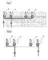
- the 4 coils 20, 22, 24, and 26 of one of the five phases are represented on the figure 6 .
- the cross and the tip illustrate the winding direction of the coils. More specifically, on the first coil 20 at the top right the cross illustrates the departure of the current behind a tooth 16 and the tip illustrates the return of the current to the front of the tooth 16. On the second coil 22 at the top left the cross illustrates the departure of the current behind a tooth 16 and the tip illustrates the return of the current to the front of the tooth 16.
- first, second, third and fourth coils respectively correspond to coils 20, 22, 24 and 26 of Figures 7 and 8 following.
- each phase consists of four coils, equivalently arranged in a combination of coils in series and coils in parallel.
- some of the terminals, connections and coils are shown in bold lines. This corresponds to the coils 20, 22, 24 and 26 of one of the 5 phases. More precisely, it can be seen that for the visible portion in bold line on the figure 7 two coils 20 and 22 are connected in series forming an assembly which is mounted antiparallel to a second assembly formed by the series connection of two coils 24 and 26.
- This antiparallel arrangement has the advantage of reducing the current per coil and de facto be able to wind with wire of smaller diameter which is an advantage for machines with high coil currents and low voltage applications.
- each phase is constituted by four coils, equivalently arranged in a combination of four coils in series. More specifically, it can be seen that for the phase illustrated on the figure 8 , two coils 20 and 22 are connected in series forming an assembly which is mounted in series head-to-tail relative to a second assembly formed by the series connection of two coils 24 and 26. This series of series head to tail is particularly suitable for high voltage applications.
- the method comprises a determination step 90 for the number of phases of the machine, the number of notches (8) and the number of poles to be provided for the machine and presenting the best compromise for the operation of the machine with respect to criteria.
- the calculation step 92 comprises a pair of numbers, a weighting 921 of the values of at least one of the criteria so as to obtain for said pair of numbers, a characteristic parameter that can be compared with the characteristic parameters of other pairs of selected ones of said plurality of pairs of numbers.
- the calculation step 92 comprises for said pair of numbers, a calculation 922 of the SPP ratio obtained by dividing the number of notches of said pair of numbers by the number of phases of the machine and the number of poles of said pair of numbers.
- the method further comprises a step of producing a rotor 100 for receiving the determined number of poles,
- the embodiment step 100 comprises a step of machining the rotor 4 to form recesses 10 for receiving magnets and / or for forming radial arms for receiving coils;
Landscapes
- Engineering & Computer Science (AREA)
- Power Engineering (AREA)
- Manufacture Of Motors, Generators (AREA)
- Windings For Motors And Generators (AREA)
- Iron Core Of Rotating Electric Machines (AREA)
Applications Claiming Priority (1)
| Application Number | Priority Date | Filing Date | Title |
|---|---|---|---|
| FR1354404A FR3005811B1 (fr) | 2013-05-16 | 2013-05-16 | Procede de fabrication d'une machine electrique tournante synchrone polyphasee, et machine correspondante |
Publications (3)
| Publication Number | Publication Date |
|---|---|
| EP2804299A2 true EP2804299A2 (de) | 2014-11-19 |
| EP2804299A3 EP2804299A3 (de) | 2016-11-30 |
| EP2804299B1 EP2804299B1 (de) | 2022-10-26 |
Family
ID=48746041
Family Applications (1)
| Application Number | Title | Priority Date | Filing Date |
|---|---|---|---|
| EP14168344.1A Active EP2804299B1 (de) | 2013-05-16 | 2014-05-14 | Rotierende elektrischen Synchronmaschine mit mehreren Phasen |
Country Status (2)
| Country | Link |
|---|---|
| EP (1) | EP2804299B1 (de) |
| FR (1) | FR3005811B1 (de) |
Citations (2)
| Publication number | Priority date | Publication date | Assignee | Title |
|---|---|---|---|---|
| FR2887698A1 (fr) | 2005-06-28 | 2006-12-29 | Valeo Equip Electr Moteur | Rotor a poles saillants comportant des flasques de maintien comportant des surfaces de contact avec des chignons des bobinages |
| WO2010146368A2 (en) | 2009-06-19 | 2010-12-23 | University Of Strathclyde | An electrical machine |
Family Cites Families (5)
| Publication number | Priority date | Publication date | Assignee | Title |
|---|---|---|---|---|
| GB2289991B (en) * | 1994-05-23 | 1998-12-02 | Ching Chuen Chan | A permanent magnet brushless dc motor |
| DE10009462A1 (de) * | 2000-02-28 | 2001-08-30 | Vlado Ostovic | Pol-Phasen-Modulation (PPM) in permanentmagneterregten elektrischen Maschinen |
| DE102004044699B4 (de) * | 2004-09-15 | 2006-08-31 | Siemens Ag | Synchronmaschine |
| JP4715934B2 (ja) * | 2009-02-20 | 2011-07-06 | 株式会社デンソー | 5相モータ |
| CN102113204B (zh) * | 2009-04-13 | 2013-06-19 | 松下电器产业株式会社 | 同步电动机驱动系统 |
-
2013
- 2013-05-16 FR FR1354404A patent/FR3005811B1/fr active Active
-
2014
- 2014-05-14 EP EP14168344.1A patent/EP2804299B1/de active Active
Patent Citations (2)
| Publication number | Priority date | Publication date | Assignee | Title |
|---|---|---|---|---|
| FR2887698A1 (fr) | 2005-06-28 | 2006-12-29 | Valeo Equip Electr Moteur | Rotor a poles saillants comportant des flasques de maintien comportant des surfaces de contact avec des chignons des bobinages |
| WO2010146368A2 (en) | 2009-06-19 | 2010-12-23 | University Of Strathclyde | An electrical machine |
Also Published As
| Publication number | Publication date |
|---|---|
| FR3005811B1 (fr) | 2022-01-21 |
| FR3005811A1 (fr) | 2014-11-21 |
| EP2804299B1 (de) | 2022-10-26 |
| EP2804299A3 (de) | 2016-11-30 |
Similar Documents
| Publication | Publication Date | Title |
|---|---|---|
| FR2852461A1 (fr) | Stator pour machine dynamo-electriques | |
| WO1998047216A1 (fr) | Machine polyphasee sans balais, notamment alternateur de vehicule automobile | |
| EP1152516B1 (de) | Elektrische rotierende Maschine mit Flusskonzentrationsrotor und um Zähne gewickelter Stator | |
| EP1251622B1 (de) | Spule für drehende elektrische Maschine | |
| WO1998059409A1 (fr) | Procede de bobinage en deux plans d'encoche pour une machine electrique tournante | |
| WO2014174200A2 (fr) | Élément isolant muni de crochets de maintien de fils de bobinage d'un stator de machine électrique et stator correspondant | |
| EP3811505B1 (de) | Elektrisch umlaufende maschine mit läuferanordnung zur verminderung der drehmomentschwankungen | |
| FR3078207A1 (fr) | Stator d'une machine electrique avec double insertion de bobinages dans les encoches | |
| FR3066333A1 (fr) | Rotor a poles vrilles pour machine electrique tournante synchrone. | |
| CH715403B1 (fr) | Machine électrique rotative. | |
| FR2645685A1 (fr) | Enroulements bobines sur gabarit, a etages multiples pour moteur a reluctance commutee | |
| EP2804299B1 (de) | Rotierende elektrischen Synchronmaschine mit mehreren Phasen | |
| WO2019012010A1 (fr) | Procede de pilotage d'une machine electrique tournante polyphasee et machine electrique tournante mettant en oeuvre ce procede | |
| FR2918512A1 (fr) | Machine electrique tournante conformee pour pouvoir fonctionner sous au moins deux tensions electriques differentes | |
| EP2078332B1 (de) | Mit ferromagnetischen Interpolarelementen optimierter Breite ausgestatteter Zahnrotor und mit einem solchen Rotor ausgestattete Drehmaschine | |
| FR2961037A1 (fr) | Realisation d'une phase de machine homopolaire tournante, applique a la conception de son circuit magnetique | |
| WO2011018716A2 (fr) | Machine electri que tournante comportant une excitatrice | |
| FR3076406A1 (fr) | Rotor de machine electrique tournante et procede de fabrication associe | |
| FR3076407A1 (fr) | Rotor de machine electrique tournante et procede de fabrication associe | |
| WO2015001268A2 (fr) | Démarreur de véhicule automobile | |
| CA2294106C (fr) | Procede de bobinage et bobines pour machine electrique tournante | |
| FR3069117B1 (fr) | Procede de bobinage ameliore d'un stator de machine electrique tournante et stator bobine correspondant | |
| EP4160880A1 (de) | Elektromotor, stator für einen elektromotor und zugehöriges herstellungsverfahren | |
| FR3126567A1 (fr) | Procédé de bobinage d'un stator de machine électrique tournante à multi-encoches par pôle et par phase | |
| EP4125182A1 (de) | Elektromotor, stator für einen elektromotor und zugehöriges herstellungsverfahren |
Legal Events
| Date | Code | Title | Description |
|---|---|---|---|
| PUAI | Public reference made under article 153(3) epc to a published international application that has entered the european phase |
Free format text: ORIGINAL CODE: 0009012 |
|
| 17P | Request for examination filed |
Effective date: 20140514 |
|
| AK | Designated contracting states |
Kind code of ref document: A2 Designated state(s): AL AT BE BG CH CY CZ DE DK EE ES FI FR GB GR HR HU IE IS IT LI LT LU LV MC MK MT NL NO PL PT RO RS SE SI SK SM TR |
|
| AX | Request for extension of the european patent |
Extension state: BA ME |
|
| RIC1 | Information provided on ipc code assigned before grant |
Ipc: H02K 29/03 20060101AFI20160715BHEP Ipc: H02K 1/27 20060101ALI20160715BHEP Ipc: H02K 3/28 20060101ALN20160715BHEP Ipc: H02K 21/16 20060101ALI20160715BHEP |
|
| PUAL | Search report despatched |
Free format text: ORIGINAL CODE: 0009013 |
|
| AK | Designated contracting states |
Kind code of ref document: A3 Designated state(s): AL AT BE BG CH CY CZ DE DK EE ES FI FR GB GR HR HU IE IS IT LI LT LU LV MC MK MT NL NO PL PT RO RS SE SI SK SM TR |
|
| AX | Request for extension of the european patent |
Extension state: BA ME |
|
| RIC1 | Information provided on ipc code assigned before grant |
Ipc: H02K 21/16 20060101ALI20161024BHEP Ipc: H02K 1/27 20060101ALI20161024BHEP Ipc: H02K 29/03 20060101AFI20161024BHEP Ipc: H02K 3/28 20060101ALN20161024BHEP |
|
| STAA | Information on the status of an ep patent application or granted ep patent |
Free format text: STATUS: EXAMINATION IS IN PROGRESS |
|
| 17Q | First examination report despatched |
Effective date: 20200602 |
|
| GRAP | Despatch of communication of intention to grant a patent |
Free format text: ORIGINAL CODE: EPIDOSNIGR1 |
|
| STAA | Information on the status of an ep patent application or granted ep patent |
Free format text: STATUS: GRANT OF PATENT IS INTENDED |
|
| RIC1 | Information provided on ipc code assigned before grant |
Ipc: H02K 3/28 20060101ALN20220215BHEP Ipc: H02K 21/16 20060101ALI20220215BHEP Ipc: H02K 1/276 20220101ALI20220215BHEP Ipc: H02K 29/03 20060101AFI20220215BHEP |
|
| GRAJ | Information related to disapproval of communication of intention to grant by the applicant or resumption of examination proceedings by the epo deleted |
Free format text: ORIGINAL CODE: EPIDOSDIGR1 |
|
| STAA | Information on the status of an ep patent application or granted ep patent |
Free format text: STATUS: EXAMINATION IS IN PROGRESS |
|
| INTG | Intention to grant announced |
Effective date: 20220321 |
|
| INTC | Intention to grant announced (deleted) | ||
| RIC1 | Information provided on ipc code assigned before grant |
Ipc: H02K 3/28 20060101ALN20220407BHEP Ipc: H02K 21/16 20060101ALI20220407BHEP Ipc: H02K 1/276 20220101ALI20220407BHEP Ipc: H02K 29/03 20060101AFI20220407BHEP |
|
| GRAP | Despatch of communication of intention to grant a patent |
Free format text: ORIGINAL CODE: EPIDOSNIGR1 |
|
| STAA | Information on the status of an ep patent application or granted ep patent |
Free format text: STATUS: GRANT OF PATENT IS INTENDED |
|
| INTG | Intention to grant announced |
Effective date: 20220516 |
|
| RBV | Designated contracting states (corrected) |
Designated state(s): AL AT BE BG CH CY CZ DE DK EE ES FI GB GR HR HU IE IS IT LI LT LU LV MC MK MT NL NO PL PT RO RS SE SI SK SM TR |
|
| GRAS | Grant fee paid |
Free format text: ORIGINAL CODE: EPIDOSNIGR3 |
|
| GRAA | (expected) grant |
Free format text: ORIGINAL CODE: 0009210 |
|
| STAA | Information on the status of an ep patent application or granted ep patent |
Free format text: STATUS: THE PATENT HAS BEEN GRANTED |
|
| AK | Designated contracting states |
Kind code of ref document: B1 Designated state(s): AL AT BE BG CH CY CZ DE DK EE ES FI GB GR HR HU IE IS IT LI LT LU LV MC MK MT NL NO PL PT RO RS SE SI SK SM TR |
|
| REG | Reference to a national code |
Ref country code: GB Ref legal event code: FG4D Free format text: NOT ENGLISH |
|
| REG | Reference to a national code |
Ref country code: CH Ref legal event code: EP |
|
| REG | Reference to a national code |
Ref country code: AT Ref legal event code: REF Ref document number: 1527792 Country of ref document: AT Kind code of ref document: T Effective date: 20221115 |
|
| REG | Reference to a national code |
Ref country code: DE Ref legal event code: R096 Ref document number: 602014085312 Country of ref document: DE |
|
| REG | Reference to a national code |
Ref country code: IE Ref legal event code: FG4D Free format text: LANGUAGE OF EP DOCUMENT: FRENCH |
|
| REG | Reference to a national code |
Ref country code: LT Ref legal event code: MG9D |
|
| REG | Reference to a national code |
Ref country code: NL Ref legal event code: MP Effective date: 20221026 |
|
| REG | Reference to a national code |
Ref country code: AT Ref legal event code: MK05 Ref document number: 1527792 Country of ref document: AT Kind code of ref document: T Effective date: 20221026 |
|
| PG25 | Lapsed in a contracting state [announced via postgrant information from national office to epo] |
Ref country code: NL Free format text: LAPSE BECAUSE OF FAILURE TO SUBMIT A TRANSLATION OF THE DESCRIPTION OR TO PAY THE FEE WITHIN THE PRESCRIBED TIME-LIMIT Effective date: 20221026 |
|
| PG25 | Lapsed in a contracting state [announced via postgrant information from national office to epo] |
Ref country code: SE Free format text: LAPSE BECAUSE OF FAILURE TO SUBMIT A TRANSLATION OF THE DESCRIPTION OR TO PAY THE FEE WITHIN THE PRESCRIBED TIME-LIMIT Effective date: 20221026 Ref country code: PT Free format text: LAPSE BECAUSE OF FAILURE TO SUBMIT A TRANSLATION OF THE DESCRIPTION OR TO PAY THE FEE WITHIN THE PRESCRIBED TIME-LIMIT Effective date: 20230227 Ref country code: NO Free format text: LAPSE BECAUSE OF FAILURE TO SUBMIT A TRANSLATION OF THE DESCRIPTION OR TO PAY THE FEE WITHIN THE PRESCRIBED TIME-LIMIT Effective date: 20230126 Ref country code: LT Free format text: LAPSE BECAUSE OF FAILURE TO SUBMIT A TRANSLATION OF THE DESCRIPTION OR TO PAY THE FEE WITHIN THE PRESCRIBED TIME-LIMIT Effective date: 20221026 Ref country code: FI Free format text: LAPSE BECAUSE OF FAILURE TO SUBMIT A TRANSLATION OF THE DESCRIPTION OR TO PAY THE FEE WITHIN THE PRESCRIBED TIME-LIMIT Effective date: 20221026 Ref country code: ES Free format text: LAPSE BECAUSE OF FAILURE TO SUBMIT A TRANSLATION OF THE DESCRIPTION OR TO PAY THE FEE WITHIN THE PRESCRIBED TIME-LIMIT Effective date: 20221026 Ref country code: AT Free format text: LAPSE BECAUSE OF FAILURE TO SUBMIT A TRANSLATION OF THE DESCRIPTION OR TO PAY THE FEE WITHIN THE PRESCRIBED TIME-LIMIT Effective date: 20221026 |
|
| PG25 | Lapsed in a contracting state [announced via postgrant information from national office to epo] |
Ref country code: RS Free format text: LAPSE BECAUSE OF FAILURE TO SUBMIT A TRANSLATION OF THE DESCRIPTION OR TO PAY THE FEE WITHIN THE PRESCRIBED TIME-LIMIT Effective date: 20221026 Ref country code: PL Free format text: LAPSE BECAUSE OF FAILURE TO SUBMIT A TRANSLATION OF THE DESCRIPTION OR TO PAY THE FEE WITHIN THE PRESCRIBED TIME-LIMIT Effective date: 20221026 Ref country code: LV Free format text: LAPSE BECAUSE OF FAILURE TO SUBMIT A TRANSLATION OF THE DESCRIPTION OR TO PAY THE FEE WITHIN THE PRESCRIBED TIME-LIMIT Effective date: 20221026 Ref country code: IS Free format text: LAPSE BECAUSE OF FAILURE TO SUBMIT A TRANSLATION OF THE DESCRIPTION OR TO PAY THE FEE WITHIN THE PRESCRIBED TIME-LIMIT Effective date: 20230226 Ref country code: HR Free format text: LAPSE BECAUSE OF FAILURE TO SUBMIT A TRANSLATION OF THE DESCRIPTION OR TO PAY THE FEE WITHIN THE PRESCRIBED TIME-LIMIT Effective date: 20221026 Ref country code: GR Free format text: LAPSE BECAUSE OF FAILURE TO SUBMIT A TRANSLATION OF THE DESCRIPTION OR TO PAY THE FEE WITHIN THE PRESCRIBED TIME-LIMIT Effective date: 20230127 |
|
| P01 | Opt-out of the competence of the unified patent court (upc) registered |
Effective date: 20230528 |
|
| REG | Reference to a national code |
Ref country code: DE Ref legal event code: R097 Ref document number: 602014085312 Country of ref document: DE |
|
| PG25 | Lapsed in a contracting state [announced via postgrant information from national office to epo] |
Ref country code: SM Free format text: LAPSE BECAUSE OF FAILURE TO SUBMIT A TRANSLATION OF THE DESCRIPTION OR TO PAY THE FEE WITHIN THE PRESCRIBED TIME-LIMIT Effective date: 20221026 Ref country code: RO Free format text: LAPSE BECAUSE OF FAILURE TO SUBMIT A TRANSLATION OF THE DESCRIPTION OR TO PAY THE FEE WITHIN THE PRESCRIBED TIME-LIMIT Effective date: 20221026 Ref country code: EE Free format text: LAPSE BECAUSE OF FAILURE TO SUBMIT A TRANSLATION OF THE DESCRIPTION OR TO PAY THE FEE WITHIN THE PRESCRIBED TIME-LIMIT Effective date: 20221026 Ref country code: DK Free format text: LAPSE BECAUSE OF FAILURE TO SUBMIT A TRANSLATION OF THE DESCRIPTION OR TO PAY THE FEE WITHIN THE PRESCRIBED TIME-LIMIT Effective date: 20221026 Ref country code: CZ Free format text: LAPSE BECAUSE OF FAILURE TO SUBMIT A TRANSLATION OF THE DESCRIPTION OR TO PAY THE FEE WITHIN THE PRESCRIBED TIME-LIMIT Effective date: 20221026 |
|
| PG25 | Lapsed in a contracting state [announced via postgrant information from national office to epo] |
Ref country code: SK Free format text: LAPSE BECAUSE OF FAILURE TO SUBMIT A TRANSLATION OF THE DESCRIPTION OR TO PAY THE FEE WITHIN THE PRESCRIBED TIME-LIMIT Effective date: 20221026 Ref country code: AL Free format text: LAPSE BECAUSE OF FAILURE TO SUBMIT A TRANSLATION OF THE DESCRIPTION OR TO PAY THE FEE WITHIN THE PRESCRIBED TIME-LIMIT Effective date: 20221026 |
|
| PLBE | No opposition filed within time limit |
Free format text: ORIGINAL CODE: 0009261 |
|
| STAA | Information on the status of an ep patent application or granted ep patent |
Free format text: STATUS: NO OPPOSITION FILED WITHIN TIME LIMIT |
|
| 26N | No opposition filed |
Effective date: 20230727 |
|
| PG25 | Lapsed in a contracting state [announced via postgrant information from national office to epo] |
Ref country code: SI Free format text: LAPSE BECAUSE OF FAILURE TO SUBMIT A TRANSLATION OF THE DESCRIPTION OR TO PAY THE FEE WITHIN THE PRESCRIBED TIME-LIMIT Effective date: 20221026 |
|
| REG | Reference to a national code |
Ref country code: CH Ref legal event code: PL |
|
| PG25 | Lapsed in a contracting state [announced via postgrant information from national office to epo] |
Ref country code: MC Free format text: LAPSE BECAUSE OF FAILURE TO SUBMIT A TRANSLATION OF THE DESCRIPTION OR TO PAY THE FEE WITHIN THE PRESCRIBED TIME-LIMIT Effective date: 20221026 |
|
| GBPC | Gb: european patent ceased through non-payment of renewal fee |
Effective date: 20230514 |
|
| REG | Reference to a national code |
Ref country code: BE Ref legal event code: MM Effective date: 20230531 |
|
| PG25 | Lapsed in a contracting state [announced via postgrant information from national office to epo] |
Ref country code: MC Free format text: LAPSE BECAUSE OF FAILURE TO SUBMIT A TRANSLATION OF THE DESCRIPTION OR TO PAY THE FEE WITHIN THE PRESCRIBED TIME-LIMIT Effective date: 20221026 Ref country code: LU Free format text: LAPSE BECAUSE OF NON-PAYMENT OF DUE FEES Effective date: 20230514 Ref country code: LI Free format text: LAPSE BECAUSE OF NON-PAYMENT OF DUE FEES Effective date: 20230531 Ref country code: CH Free format text: LAPSE BECAUSE OF NON-PAYMENT OF DUE FEES Effective date: 20230531 |
|
| REG | Reference to a national code |
Ref country code: IE Ref legal event code: MM4A |
|
| PG25 | Lapsed in a contracting state [announced via postgrant information from national office to epo] |
Ref country code: IE Free format text: LAPSE BECAUSE OF NON-PAYMENT OF DUE FEES Effective date: 20230514 |
|
| PG25 | Lapsed in a contracting state [announced via postgrant information from national office to epo] |
Ref country code: IE Free format text: LAPSE BECAUSE OF NON-PAYMENT OF DUE FEES Effective date: 20230514 Ref country code: GB Free format text: LAPSE BECAUSE OF NON-PAYMENT OF DUE FEES Effective date: 20230514 |
|
| PG25 | Lapsed in a contracting state [announced via postgrant information from national office to epo] |
Ref country code: IT Free format text: LAPSE BECAUSE OF FAILURE TO SUBMIT A TRANSLATION OF THE DESCRIPTION OR TO PAY THE FEE WITHIN THE PRESCRIBED TIME-LIMIT Effective date: 20221026 Ref country code: BE Free format text: LAPSE BECAUSE OF NON-PAYMENT OF DUE FEES Effective date: 20230531 |
|
| PG25 | Lapsed in a contracting state [announced via postgrant information from national office to epo] |
Ref country code: BG Free format text: LAPSE BECAUSE OF FAILURE TO SUBMIT A TRANSLATION OF THE DESCRIPTION OR TO PAY THE FEE WITHIN THE PRESCRIBED TIME-LIMIT Effective date: 20221026 |
|
| PG25 | Lapsed in a contracting state [announced via postgrant information from national office to epo] |
Ref country code: BG Free format text: LAPSE BECAUSE OF FAILURE TO SUBMIT A TRANSLATION OF THE DESCRIPTION OR TO PAY THE FEE WITHIN THE PRESCRIBED TIME-LIMIT Effective date: 20221026 |
|
| PGFP | Annual fee paid to national office [announced via postgrant information from national office to epo] |
Ref country code: DE Payment date: 20250513 Year of fee payment: 12 |
|
| PG25 | Lapsed in a contracting state [announced via postgrant information from national office to epo] |
Ref country code: CY Free format text: LAPSE BECAUSE OF FAILURE TO SUBMIT A TRANSLATION OF THE DESCRIPTION OR TO PAY THE FEE WITHIN THE PRESCRIBED TIME-LIMIT; INVALID AB INITIO Effective date: 20140514 |
|
| PG25 | Lapsed in a contracting state [announced via postgrant information from national office to epo] |
Ref country code: HU Free format text: LAPSE BECAUSE OF FAILURE TO SUBMIT A TRANSLATION OF THE DESCRIPTION OR TO PAY THE FEE WITHIN THE PRESCRIBED TIME-LIMIT; INVALID AB INITIO Effective date: 20140514 |
|
| PG25 | Lapsed in a contracting state [announced via postgrant information from national office to epo] |
Ref country code: TR Free format text: LAPSE BECAUSE OF FAILURE TO SUBMIT A TRANSLATION OF THE DESCRIPTION OR TO PAY THE FEE WITHIN THE PRESCRIBED TIME-LIMIT Effective date: 20221026 |