EP2803577B1 - Modifizierbares Flugzeugmodul - Google Patents
Modifizierbares Flugzeugmodul Download PDFInfo
- Publication number
- EP2803577B1 EP2803577B1 EP14167993.6A EP14167993A EP2803577B1 EP 2803577 B1 EP2803577 B1 EP 2803577B1 EP 14167993 A EP14167993 A EP 14167993A EP 2803577 B1 EP2803577 B1 EP 2803577B1
- Authority
- EP
- European Patent Office
- Prior art keywords
- aircraft
- region
- functional module
- functional
- operational position
- Prior art date
- Legal status (The legal status is an assumption and is not a legal conclusion. Google has not performed a legal analysis and makes no representation as to the accuracy of the status listed.)
- Active
Links
- 238000009434 installation Methods 0.000 claims description 10
- 239000000463 material Substances 0.000 claims description 10
- 238000005192 partition Methods 0.000 claims description 7
- 230000033001 locomotion Effects 0.000 claims description 6
- 238000000034 method Methods 0.000 claims description 6
- 230000004308 accommodation Effects 0.000 claims description 3
- 238000006073 displacement reaction Methods 0.000 claims description 3
- 230000003292 diminished effect Effects 0.000 description 6
- 230000009977 dual effect Effects 0.000 description 1
- 230000010006 flight Effects 0.000 description 1
- 230000001771 impaired effect Effects 0.000 description 1
- XLYOFNOQVPJJNP-UHFFFAOYSA-N water Substances O XLYOFNOQVPJJNP-UHFFFAOYSA-N 0.000 description 1
Images

Classifications
-
- B—PERFORMING OPERATIONS; TRANSPORTING
- B64—AIRCRAFT; AVIATION; COSMONAUTICS
- B64D—EQUIPMENT FOR FITTING IN OR TO AIRCRAFT; FLIGHT SUITS; PARACHUTES; ARRANGEMENT OR MOUNTING OF POWER PLANTS OR PROPULSION TRANSMISSIONS IN AIRCRAFT
- B64D11/00—Passenger or crew accommodation; Flight-deck installations not otherwise provided for
- B64D11/02—Toilet fittings
-
- B—PERFORMING OPERATIONS; TRANSPORTING
- B64—AIRCRAFT; AVIATION; COSMONAUTICS
- B64D—EQUIPMENT FOR FITTING IN OR TO AIRCRAFT; FLIGHT SUITS; PARACHUTES; ARRANGEMENT OR MOUNTING OF POWER PLANTS OR PROPULSION TRANSMISSIONS IN AIRCRAFT
- B64D11/00—Passenger or crew accommodation; Flight-deck installations not otherwise provided for
- B64D11/04—Galleys
-
- B—PERFORMING OPERATIONS; TRANSPORTING
- B64—AIRCRAFT; AVIATION; COSMONAUTICS
- B64D—EQUIPMENT FOR FITTING IN OR TO AIRCRAFT; FLIGHT SUITS; PARACHUTES; ARRANGEMENT OR MOUNTING OF POWER PLANTS OR PROPULSION TRANSMISSIONS IN AIRCRAFT
- B64D11/00—Passenger or crew accommodation; Flight-deck installations not otherwise provided for
- B64D2011/0046—Modular or preassembled units for creating cabin interior structures
Definitions
- the invention relates to an aircraft monument provided for installation in an aircraft cabin, and also to an aircraft region including an aircraft monument of such a type.
- the invention further relates to a process for operating an aircraft equipped with an aircraft monument of such a type and/or with an aircraft region of such a type.
- galleys Modern commercial aircraft usually are equipped with on-board kitchens, so-called galleys, which are known, for example, from DE 10 2006 023 047 B4 or US 7,780,114 B2 .
- the galleys are installed in the door-entry regions of the aircraft cabin and comprise a body with a substantially rectangular outline, which is oriented parallel to a door aisle extending in the direction of an aircraft door. Via the door aisle, which extends substantially perpendicular to a main aisle running along a longitudinal axis of the aircraft cabin, passengers can get out of the aircraft or into the aircraft.
- an aircraft monument for installation in an aircraft cabin which comprises a sanitary module with a sanitary device and also a kitchen module arranged adjacent to the sanitary module.
- the kitchen module comprises a trolley parking space and also a working surface, the trolley parking space being separated from the sanitary module by a partition.
- the aircraft monument described in DE 10 2011 109 390 A1 or WO 2013/017290 A1 enables the installation space requirement of an on-board kitchen in an aircraft cabin to be diminished without impeding the handling of trolleys filled with service products for the cabin personnel, and is, in particular, suitable for installation in aircraft that are employed on short-haul flights pertaining to the lower price range, on which merely a reduced service is offered to the passengers.
- DE 10 2010 012 989 A1 or WO 2011/116982 A2 proposes to equip a sanitary module, provided for installation in an aircraft cabin, in its interior space with a first trolley parking place for accommodating at least one trolley that is suitable for receiving supplies for the passengers in the aircraft cabin, in the interior space of the sanitary module. Furthermore, a second trolley parking place is provided adjacent to the sanitary module.
- the first trolley parking place in the interior space of the sanitary module can be utilised for accommodating one or more trolleys. If the aircraft is, on the other hand, at cruising altitude, the second trolley parking place is available for accommodating the trolley(s).
- EP 0 867 365 A2 describes a dual pivot expandable lavatory for use in limited spaces such as on an airplane.
- the lavatory may be positioned proximate the doorway area of the airplane, and is provided with a primary and a secondary pivotable module.
- Each module is pivotably attached to a stationary assembly conventionally affixed to the ceiling and floor of the airplane. During routine flight, both modules are pivoted into a deployed position within the doorway area, thereby increasing the lavatory interior space without affecting its base area size.
- the object underlying the invention is to specify an aircraft monument that enables an optimal exploitation of the space available in an aircraft cabin in various operational phases of the aircraft. Furthermore, the object underlying the invention is to make available an aircraft region equipped with an aircraft monument of such a type. Lastly, the invention is directed towards the object of specifying a process for operating an aircraft equipped with an aircraft monument of such a type and/or with an aircraft region of such a type.
- An aircraft monument provided for installation in an aircraft cabin comprises a first functional module and a second functional module.
- the first functional module is equipped with a side wall that is adapted to delimit the first functional module from a region of the aircraft cabin adjacent to the first functional module and/or from a region of the aircraft monument adjacent to the first functional module.
- the second functional module is arranged distant form the first functional module such as to define a functional area in between. By virtue of the side wall of the first functional module, a base area of the first functional module is consequently defined.
- the side wall is movable between a first and a second operational position and comprises a side-wall region which separates the first functional module from the second functional module and in the second operational position of the side wall is displaced in the direction of the second functional module relative to its position in the first operational position of the side wall.
- the aircraft monument consequently comprises a first functional module and a functional area, the base areas of which can, as needed, be varied in straightforward manner by movement of the side wall of the first functional module.
- the first functional module can consequently be utilised with its larger base area.
- a utilisation of the first functional module with diminished base area is possible.
- the base area of the first functional module preferably is selected in such a way that the first functional module can be utilised even when the side wall of the first functional module is in its first operational position. A greater ease of use is, however, obtained by virtue of the enlarged base area of the first functional module when the side wall of the first functional module is in its second operational position.
- the total base area of the aircraft monument remains the same in this case, so that it is always guaranteed that a region of the aircraft cabin that, for example for reasons of safety, is to be kept vacant is not impaired.
- the aircraft monument consequently enables an optimal exploitation of the space available in the aircraft cabin in various operational phases of the aircraft.
- the side wall of the first functional module exhibits a second side-wall region which merely in the second operational position of the side wall serves for delimiting the first functional module from a region of the aircraft cabin adjacent to the first functional module.
- the second side-wall region may, on the other hand, be arranged inside or outside the first functional module in such a way that it is not suitable for delimiting the first functional module from a region of the aircraft cabin adjacent to the first functional module.
- the side wall of the first functional module may exhibit a third side-wall region which merely in the second operational position of the side wall serves for delimiting the first functional module from a region of the aircraft monument adjacent to the first functional module.
- the third side-wall region may, on the other hand, be arranged inside or outside the first functional module in such a way that it is not suitable for delimiting the first functional module from a region of the aircraft monument adjacent to the first functional module.
- the second and/or the third side-wall region may, in the event of a movement of the side wall out of its first into its second operational position by swivelling, swinging, twisting, unfolding or such like, be brought into a position in which it/they is/are suitable to delimit the first functional module from a region of the aircraft cabin and/or of the aircraft monument adjacent to the first functional module.
- This can be brought about particularly easily if the second and/or third side-wall region consist(s) of a flexible material, in particular a foldable material.
- a second and/or third side-wall region consisting of a flexible material, in particular a foldable material has a merely smaller space requirement if the side wall of the first functional module is in its first operational position.
- the first functional module of the aircraft monument may be designed in the form of an arbitrary module, for example a kitchen module or a stowage-compartment module.
- the first functional module preferably is configured in the form of a sanitary module.
- the sanitary module may be equipped with a toilet and with further sanitary devices such as, for example, a washbasin with a water tap, a mirror and/or a cupboard for accommodating toilet paper, paper towels etc.
- a doorway that is capable of being closed by a door may be formed, in order to make the interior space of the first functional module accessible.
- the door may be designed in the form of a sliding door or may be capable of being swivelled between an open position and a closed position about a swivel axis which may be anchored in the region of a floor of the aircraft monument and/or in the region of a floor of an aircraft cabin equipped with the aircraft monument.
- the side wall of a first functional module configured in the form of a sanitary module may then be in its first operational position, so that the first functional module merely occupies a minimal base area. If the aircraft is, on the other hand, in cruise flight, the first functional module may be available with an enlarged base area for more comfortable utilisation.
- the functional area may be designed in the form of an arbitrary module.
- the functional area has preferably is designed in the form of a kitchen module or a stowage-compartment module.
- the combination of various modalities in a single aircraft monument enables a centralisation of systems, for example the centralisation of supply systems needed for supplying the aircraft monument.
- an autarkic aircraft monument can be realised, in which the various functional regions can be connected up, for example via common ports, to a central water-supply system, a central power-supply system and/or a central sewage-disposal system of the aircraft.
- the side wall of the first functional module may be in its first operational position, so that the first functional module occupies merely a minimal base area but the functional area designed in the form of a kitchen module or a stowage-compartment module has a larger base area.
- the functional area then offers sufficient stowage space for trolleys and other devices that have to be stowed securely during take-off, landing and taxiing of the aircraft. If the aircraft is in cruise flight, trolleys and other devices may, on the other hand, be taken out of the functional area and be utilised or accommodated elsewhere, so that the base area of the functional area can be diminished without losses of function.
- the aircraft monument may exhibit a substantially circular, square or rectangular base area. Preferably, however, the aircraft monument has an oval base area.
- the first functional module may exhibit an elliptical-segment-shaped base area.
- the base area of the first functional module preferably retains its elliptical-segment shape if the side wall of the first functional module is moved between its first operational position and its second operational position.
- the functional area may, on the other hand, exhibit a rectangular base area.
- the base area of the functional area preferably also retains its rectangular shape if the side wall of the first functional module is moved between its first operational position and its second operational position - merely a length and/or a width of the base area of the functional area can be varied in the event of a movement of the side wall of the first functional module between its first operational position and its second operational position.
- the side wall of the first functional module may be movable between its first and its second operational position by displacement of the first side-wall region, appropriate positioning of the second side-wall region, and connecting of the second side-wall region to a fourth side-wall region expanded in the second operational position of the side wall by the second side-wall region.
- the first functional module may be equipped with a first connecting arrangement, designed for example in the form of a suitable latching arrangement, which serves in the second operational position of the side wall to establish a connection between the second side-wall region and the fourth side-wall region expanded in the second operational position of the side wall by the second side-wall region.
- the side wall of the first functional module may be movable between its first and its second operational position by displacement of the first side-wall region, appropriate positioning of the third side-wall region, and connecting of the third side-wall region to a fifth side-wall region expanded in the second operational position of the side wall by the third side-wall region.
- the first functional module may then be equipped with a second connecting arrangement, designed for example in the form of a suitable latching arrangement, which serves in the second operational position of the side wall to establish a connection between the third side-wall region and the fifth side-wall region expanded in the second operational position of the side wall by the third side-wall region.
- the aircraft monument preferably includes at least two first functional modules, which do not necessarily have to serve for the same function but each are equipped with a side wall that is movable between a first and a second operational position, and consequently have a variable base area. If a first functional module is designed in the form of a sanitary module, a further first functional module may accordingly be configured also in the form of a kitchen module, a stowage-compartment module or such like, with a side wall that is movable between a first and a second operational position.
- the two first functional modules preferably are arranged adjacent to one another in such a manner that they are separated from one another by a partition which in the first operational position of the respective side walls of the first functional modules is formed by the fifth side-wall region of one of the two first functional modules.
- a partition extending between the two first functional modules may, on the other hand, be formed by the third and the fifth side-wall region of one of the two first functional modules.
- the second functional module may, for example, be designed in the form of a sanitary module, a kitchen module or a stowage-compartment module but differs from the first functional module and the functional area by virtue of the fact that it exhibits no side wall that is movable between a first and a second operational position, and consequently also does not have a variable base area.
- the first and the second functional module may be arranged in the region of portions of the aircraft monument situated substantially opposite one another. Furthermore, the first and the second functional module are separated from one another by the functional area.
- the aircraft monument includes at least two second functional modules which, in particular, may be arranged adjacent to one another and may be separated from the first functional module by the functional area.
- the aircraft monument may then comprise a central region formed by the functional area, which on sides situated substantially opposite one another adjoins a pair of first functional modules and a pair of second functional modules.
- An aircraft region includes at least one main aisle extending along a longitudinal axis of an aircraft cabin.
- the at least one main aisle may, for example, separate two passenger-seat regions of the aircraft cabin from one another, in which case each passenger-seat region may comprise a plurality of rows of passenger seats arranged one behind the other, each with three passenger seats.
- the aircraft region may include only one main aisle. It is, however, also conceivable that the aircraft region comprises more than one main aisle, e.g. two main aisles which may extend substantially parallel to each other along a longitudinal axis of an aircraft cabin.
- the aircraft region includes a door aisle which extends substantially perpendicular to the main aisle between a first and a second aircraft door.
- An aircraft monument described above is arranged in the door aisle.
- the aircraft region preferably includes at least one parking place which is adapted to receive, at least in certain operational phases of an aircraft equipped with the aircraft region, a mobile component of the functional area.
- the mobile component may be, for example, a trolley or a stowage-compartment element which, for example during cruise flight of an aircraft equipped with the aircraft region, can be removed from the functional area, so that the base area of the functional area can be diminished without losses in the function of the functional area.
- the parking place may be provided with a fastening device which is adapted to fix the mobile component of the functional area in its position on the parking place.
- the aircraft monument preferably is arranged in the door aisle in such a manner that at least a first or a second functional module faces towards a front region of the aircraft cabin, relative to the flight direction of an aircraft equipped with the aircraft region.
- the aircraft monument may also be arranged in the door aisle of an aircraft region comprising only one main aisle in such a manner that at least a first or a second functional module faces towards a rear region of the aircraft cabin, relative to the flight direction of an aircraft equipped with the aircraft region.
- the aircraft monument may be arranged in the door aisle in such a manner that at least a first or a second functional module faces towards an aircraft door.
- the aircraft monument preferably is arranged substantially centrically in the door aisle. Such an arrangement of the aircraft monument enables the aircraft monument to be utilised as part of a guiding system for emergency evacuations.
- the aircraft monument may perform a guidance function for persons moving along the main aisle(s) in the direction of the aircraft doors, since the persons are necessarily led along the outer walls of the aircraft monument in the direction of the aircraft doors. In the event of an emergency evacuation of the aircraft, this enables an increase in the door capacity, i.e. an increase in the number of persons who are able to leave the aircraft via the doors of the aircraft per unit of time.
- the side wall of the first functional module is in its first operational position during take-off, landing and taxiing.
- the space requirement of the first functional module can be minimised, and the space becoming vacant thereby can be utilised for an enlargement of the base area of the functional area.
- the side wall of the first functional module is, on the other hand, in its second operational position.
- the stowage space of the functional area which is enlarged by the positioning of the side wall of the first functional module in its first operational position, can be utilised for the accommodation of a mobile component of the functional area.
- a mobile component of the functional area can be accommodated on a parking place of the aircraft region, which is located, in particular, in a door-entry region of the aircraft region.
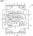
- Figures 1 to 3 each show an aircraft region 100 which is formed by a part of an aircraft cabin.
- an aircraft monument 10 is arranged in the aircraft region 100.
- the aircraft monument 10 includes two first functional modules 12 which are designed in the form of a sanitary module and comprise a toilet 14 and also further sanitary devices, in particular a washbasin 16. Over and above this, the aircraft monument 10 includes a centrally positioned functional area 18 designed in the form of a stowage-compartment module.
- the two first functional modules 12 adjoin the functional area 18.
- two third functional modules 20 adjoin the functional area 18, one of which is designed in the form of a sanitary module with a toilet 14 and with a washbasin 16, and one in the form of a sanitary module with diminished functionality, with a urinal 22 and with a washbasin 16.
- the pairs of first and second functional modules 12, 20 are consequently arranged in the region of portions of the aircraft monument 10 situated substantially opposite one another and are separated from one another by the functional area 18 constructed in the form of a stowage-compartment module.
- Each first functional module 12 includes a side wall 24 which serves to delimit the first functional module 12 from a region of the aircraft cabin adjacent to the first functional module 12 and also from a region of the aircraft monument 10 adjacent to the first functional module 12.
- the region of the aircraft monument 10 adjacent to the first functional module 12 is formed, in the embodiment of an aircraft monument 10 that is shown, in each instance by a region of the functional area 18 adjacent to the first functional module 12 and also by the further first functional module 12 adjacent to the first functional module 12.
- the side wall 24 of each first functional module 12 is movable between a first operational position (see Figure 1 ) and a second operational position (see Figures 2 and 3 ) and comprises a side-wall region 24a which separates the first functional module 12 from the second functional module20 and in the second operational position of the side wall 24 is displaced in the direction of the second functional module 20 relative to its position in the first operational position of the side wall 24.
- Side-wall region 24a of the first functional module 12 represented at the top in the Figures may be designed to be integral with side-wall region 24a of the first functional module 12 represented at the bottom in the Figures.
- side walls 25 of the second functional modules 20 in the embodiment of an aircraft monument 10 that is shown in the Figures are not movable between a first and a second operational position.
- the base area of the second functional modules 20 is consequently not variable.
- the aircraft monument 10 has an oval base area.
- Each of the first functional modules 12 has, irrespective of the operational position of the side wall 24, an elliptical-segment-shaped base area.
- the functional area 18 comprises, irrespective of the operational position of the side wall 24, a rectangular base area.
- the base area of the two second functional modules 20 has an elliptical-segment shape.
- the base areas of the first functional modules 12 are selected in such a way that the first functional modules 12, each designed in the form of a sanitary module, can be utilised also when the side wall 24 of the first functional modules 12 is in its first operational position.
- the enlarged base area of the first functional modules 12 By virtue of the enlarged base area of the first functional modules 12, however, a greater ease of use is obtained if the side walls 24 of the first functional modules 12 are in their second operational position.
- each first functional module 12 further comprises a second side-wall region 24b which merely in the second operational position of the side wall 24 serves for delimiting the first functional module 12 from a region of the aircraft cabin adjacent to the first functional module 12.
- the second side-wall region 24b is, on the other hand, arranged in an interior space of the first functional module 12, so that it is not suitable for delimiting the first functional module 12 from a region of the aircraft cabin adjacent to the first functional module 12.
- the second side-wall region 24b consists of a flexible material, in particular a foldable material. As a result, the second side-wall region 24b can be stowed in space-saving manner in the interior space of the first functional module 12.
- the side wall 24 of the first functional module 12 represented at the top in the Figures comprises a third side-wall region 24c consisting of a flexible material, in particular a foldable material, which merely in the second operational position of the side wall 24 serves for delimiting the first functional module 12 represented at the top in the Figures from a region of the aircraft monument 10 adjacent to the first functional module 12, which in the embodiment of an aircraft monument 10 shown in the Figures is formed by the first functional module 12 represented at the bottom in the Figures. If the side wall 24 of the first functional module 12 represented at the top in the Figures is in its first operational position, the third side-wall region 24c is stowed within the first functional module.
- first side-wall region 24a is displaced out of its position illustrated in Figure 1 in the direction of the second functional module 20 into its position shown in Figures 2 and 3 .
- each second side-wall region 24b is positioned appropriately and connected by means of a first connecting arrangement 26, designed for example in the form of a suitable latching arrangement, to a fourth side-wall region 24d expanded in the second operational position of the side wall 24 by the second side-wall region 24b.
- the third side-wall region 24c of the first functional module 12 represented at the top in the Figures is positioned appropriately and connected by means of a second connecting arrangement 28, designed for example likewise in the form of a suitable latching arrangement, to a fifth side-wall region 24e expanded in the second operational position of the side wall 24 by the third side-wall region 24c.
- the two first functional modules 12 of the aircraft monument 10 are arranged adjacent to one another in such a manner that they are separated from one another by a partition which in the first operational position of the respective side walls 24 of the first functional modules 12 is formed by the fifth side-wall region 24e of the first functional module 12 represented at the top in the Figures.
- the partition extending between the two first functional modules 12 is, on the other hand, formed by the third and the fifth side-wall region 24c, 24e of the first functional module 12 represented at the top in the Figures.
- the side wall 24 of the first functional module 12 represented at the bottom in the Figures consequently comprises no third or fifth side-wall region, as a result of which a lightweight design of the aircraft monument 10 becomes possible.
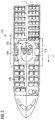
- the aircraft monument 10 is arranged in the aircraft region 100 centrically in a door aisle 102 which extends between a first and a second aircraft door 104, 106 and substantially perpendicular to a main aisle 108 running along a longitudinal axis L of the aircraft cabin.
- the door aisle 102 consequently separates a front part of the aircraft cabin from a rear part of the aircraft cabin, viewed in the flight direction F.
- the aircraft monument 10 arranged centrically in the door aisle 102 is consequently arranged between the front and the rear part of the aircraft cabin, with the first functional modules 12 facing towards the front part of the aircraft cabin, and the second functional modules 20 facing towards the rear part of the aircraft cabin.
- the aircraft monument 10 may be arranged centrically in the door aisle 102 in such a manner that the first and the third functional modules 12, 20 face the aircraft doors 104, 106.
- the aircraft monument 10 performs a guidance function for persons moving along the main aisle 108 in the direction of the aircraft doors 104, 106.
- these persons are led along the side walls 24 of the first functional modules 12 and also along side walls 25 of the second functional modules 20 in the direction of the aircraft doors 104, 106.
- the side wall 24 of the first functional modules 12 is in its first or its second operational position.
- the side wall 24 of the first functional modules 12 configured in the form of sanitary modules is in its first operational position.
- the first functional modules 12 occupy merely a minimal base area
- the functional area 18 configured in the form of a stowage-compartment module has a larger base area and consequently offers sufficient stowage space for trolleys 30, a stowage-compartment element 32 and other devices that have to be stowed securely during take-off, landing and taxiing of the aircraft.
- trolleys 31 are stowed adjacent to the aircraft doors 104, 106 both during take-off, landing and taxiing and in cruise flight of the aircraft.
- the side wall 24 of the first functional modules 12 configured in the form of sanitary modules can be brought into its second operational position.
- the first functional modules 12 are then available with an enlarged base area for more comfortable utilisation.
- Mobile components of the functional area 18, such as, for example, the trolleys 30 and/or the stowage-compartment element 32, may, on the other hand, be removed from the functional area 18 and may be utilised or may be accommodated on suitable parking places 110 provided in the aircraft region 100. Consequently the base area of the functional area 18 can be diminished without losses of function.
- the parking places 110 are provided in each instance with a fastening device not illustrated in the Figures, which serves to fix a mobile component of the functional area 18 in its position on the parking place 110.
Landscapes
- Engineering & Computer Science (AREA)
- Aviation & Aerospace Engineering (AREA)
- Buildings Adapted To Withstand Abnormal External Influences (AREA)
- Power-Operated Mechanisms For Wings (AREA)
- Aiming, Guidance, Guns With A Light Source, Armor, Camouflage, And Targets (AREA)
- Residential Or Office Buildings (AREA)
- Seats For Vehicles (AREA)
Claims (15)
- Flugzeugmonument (10) zur Installation in einer Flugzeugkabine mit:- einem ersten Funktionsmodul (12),- einem zweiten Funktionsmodul (20), das in einem Abstand von dem ersten Funktionsmodul (12) angeordnet ist, um dazwischen einen funktionalen Bereich (18) zu definieren, und- einer Seitenwand (24) zur Abgrenzung des ersten Funktionsmoduls (12) von einem zu dem ersten Funktionsmodul (12) benachbarten Bereich der Flugzeugkabine und/oder einem zu dem ersten Funktionsmodul (12) benachbarten Bereich des Flugzeugmonuments (10), wobei die Seitenwand (24) zwischen einer ersten und einer zweiten Betriebsposition bewegbar ist und einen ersten Seitenwandbereich (24a) aufweist, der das erste Funktionsmodul (12) von dem zweiten Funktionsmodul (20) trennt und in der zweiten Betriebsposition der Seitenwand (24) relativ zu seiner Position in der ersten Betriebsposition der Seitenwand (24) in Richtung des zweiten Funktionsmoduls (20) verschoben ist, so dass so dass eine Bewegung der Seitenwand (24) aus ihrer ersten Betriebsposition in ihre zweite Betriebsposition eine Vergrößerung einer Grundfläche des ersten Funktionsmoduls (12) sowie eine entsprechende Verkleinerung einer Grundfläche des funktionalen Bereichs (18) zur Folge hat,dadurch gekennzeichnet, dass die Seitenwand (24) einen zweiten Seitenwandbereich (24b) aufweist, der lediglich in der zweiten Betriebsposition der Seitenwand (24) der Abgrenzung des ersten Funktionsmoduls (12) von einem zu dem ersten Funktionsmodul (12) benachbarten Bereich der Flugzeugkabine dient.
- Flugzeugmonument nach Anspruch 1,
dadurch gekennzeichnet, dass die Seitenwand (24) einen dritten Seitenwandbereich (24c) aufweist, der lediglich in der zweiten Betriebsposition der Seitenwand (24) der Abgrenzung des ersten Funktionsmoduls (12) von einem zu dem ersten Funktionsmodul (12) benachbarten Bereich des Flugzeugmonuments (10) dient. - Flugzeugmonument nach Anspruch 1 oder 2,
dadurch gekennzeichnet, dass das der zweite und/oder der dritte Seitenwandbereich (24b, 24c) aus einem flexiblen, insbesondere einem faltbaren Material besteht/bestehen. - Flugzeugmonument nach einem der Ansprüche 1 bis 3,
dadurch gekennzeichnet, dass das erste Funktionsmodul (12) in Form eines Sanitärmoduls ausgestaltet ist und/oder dass ein Küchenmodul oder ein Staufachmodul in dem funktionalen Bereich (18) angeordnet ist. - Flugzeugmonument nach einem der Ansprüche 1 bis 4,
dadurch gekennzeichnet, dass das Flugzeugmonument (10) eine ovale Grundfläche hat. - Flugzeugmonument nach einem der Ansprüche 1 bis 5,
dadurch gekennzeichnet, dass die Seitenwand (24) des ersten Funktionsmoduls (12) durch Verschieben des ersten Seitenwandbereichs (24a), entsprechendes Positionieren des zweiten Seitenwandbereichs (24b) und Verbinden des zweiten Seitenwandbereichs (24b) mit einem in der zweiten Betriebsposition der Seitenwand (24) durch den zweiten Seitenwandbereich (24b) erweiterten vierten Seitenwandbereich (24d) und/oder entsprechendes Positionieren des dritten Seitenwandbereichs (24c) und Verbinden des dritten Seitenwandbereichs (24c) mit einem in der zweiten Betriebsposition der Seitenwand (24) durch den dritten Seitenwandbereich (24c) erweiterten fünften Seitenwandbereich (24e) zwischen ihrer ersten und ihrer zweiten Betriebsposition bewegbar ist. - Flugzeugmonument nach einem der Ansprüche 1 bis 6,
dadurch gekennzeichnet, dass das Flugzeugmonument (10) mindestens zwei erste Funktionsmodule (12) umfasst, die insbesondere derart benachbart zueinander angeordnet sind, dass sie durch eine Trennwand voneinander getrennt sind, die in der ersten Betriebsposition der jeweiligen Seitenwände (24) der ersten Funktionsmodule (12) durch den fünften Seitenwandbereich (24e) eines der beiden ersten Funktionsmodule (12) und in der zweiten Betriebsposition der jeweiligen Seitenwände (24) der ersten Funktionsmodule (12) durch den dritten und den fünften Seitenwandbereich (24c, 24e) eines der beiden ersten Funktionsmodule (12) gebildet wird. - Flugzeugmonument nach Anspruch 7,
dadurch gekennzeichnet, dass das erste und das zweite Funktionsmodul (12, 20) im Bereich einander im Wesentlichen gegenüber liegender Abschnitte des Flugzeugmonuments (10) angeordnet sind. - Flugzeugmonument nach einem der Ansprüche 1 bis 8,
dadurch gekennzeichnet, dass das Flugzeugmonument (10) mindestens zwei zweite Funktionsmodule (20) umfasst, die insbesondere benachbart zueinander angeordnet und durch den funktionalen Bereich (18) von dem ersten Funktionsmodul (12) getrennt sind. - Flugzeugbereich (100), mit:- einem sich entlang einer Längsachse (L) einer Flugzeugkabine erstreckenden Hauptgang (108),- einem sich im Wesentlichen senkrecht zu dem Hauptgang (108) zwischen einer ersten und einer zweiten Flugzeugtür (104, 106) erstreckenden Türgang (102), und- einem in dem Türgang (102) angeordneten Flugzeugmonument (10) nach einem der Ansprüche 1 bis 9.
- Flugzeugbereich nach Anspruch 10,
gekennzeichnet durch mindestens einen Stellplatz (110), der dazu eingerichtet ist, zumindest in bestimmten Betriebsphasen eines mit dem Flugzeugbereich (100) ausgestatteten Flugzeugs eine bewegliche Komponente (30, 32) des funktionalen Bereichs (18) aufzunehmen. - Flugzeugbereich nach Anspruch 10 oder 11,
dadurch gekennzeichnet, dass das Flugzeugmonument (10) derart in dem Türgang (102) angeordnet ist, dass mindestens ein erstes oder ein zweites Funktionsmodul (12, 20) einem, bezogen auf die Flugrichtung (F) eines mit dem Flugzeugbereich (100) ausgestatteten Flugzeugs, vorderen Bereich der Flugzeugkabine zugewandt ist und/oder dass mindestens ein erstes oder ein zweites Funktionsmodul (12, 20) einem, bezogen auf die Flugrichtung (F) eines mit dem Flugzeugbereich (100) ausgestatteten Flugzeugs, rückwärtigen Bereich der Flugzeugkabine zugewandt ist. - Flugzeugbereich nach einem der Ansprüche 10 bis 12,
dadurch gekennzeichnet, dass das Flugzeugmonument (10) im Wesentlichen mittig in dem Türgang (102) angeordnet ist. - Verfahren zum Betreiben eines mit einem Flugzeugmonument (10) nach einem der Ansprüche 1 bis 9 und/oder einem Flugzeugbereich (100) nach einem der Ansprüche 10 bis 13 ausgestatteten Flugzeugs, bei dem- sich die Seitenwand (24) des ersten Funktionsmoduls (12) während Start, Landung und Taxi in ihrer ersten Betriebsposition befindet, und- sich die Seitenwand (24) des ersten Funktionsmoduls (12) während des Reiseflugs in ihrer zweiten Betriebsposition befindet.
- Verfahren nach Anspruch 14,
dadurch gekennzeichnet, dass während Start, Landung und Taxi der durch die Positionierung der Seitenwand (24) des ersten Funktionsmoduls (12) in ihrer ersten Betriebsposition vergrößerte Stauraum des funktionalen Bereichs (18) für die Unterbringung einer bewegliche Komponente (30, 32) des funktionalen Bereichs (18) genutzt wird und/oder dass während des Reiseflugs eine bewegliche Komponente (30, 32) des funktionalen Bereichs (18) auf einem Stellplatz (110) des Flugzeugbereichs (100) untergebracht wird.
Applications Claiming Priority (1)
| Application Number | Priority Date | Filing Date | Title |
|---|---|---|---|
| DE102013008309.5A DE102013008309A1 (de) | 2013-05-15 | 2013-05-15 | Modifizierbares Flugzeugmonument |
Publications (2)
| Publication Number | Publication Date |
|---|---|
| EP2803577A1 EP2803577A1 (de) | 2014-11-19 |
| EP2803577B1 true EP2803577B1 (de) | 2019-05-08 |
Family
ID=50687347
Family Applications (1)
| Application Number | Title | Priority Date | Filing Date |
|---|---|---|---|
| EP14167993.6A Active EP2803577B1 (de) | 2013-05-15 | 2014-05-12 | Modifizierbares Flugzeugmodul |
Country Status (3)
| Country | Link |
|---|---|
| US (1) | US9457903B2 (de) |
| EP (1) | EP2803577B1 (de) |
| DE (1) | DE102013008309A1 (de) |
Cited By (2)
| Publication number | Priority date | Publication date | Assignee | Title |
|---|---|---|---|---|
| EP3947148A4 (de) * | 2019-08-30 | 2022-05-25 | ST Engineering Aerospace Ltd. | Für mobilitätseingeschränkte personen zugängliche flugzeugtoilette |
| US11794902B2 (en) | 2017-10-17 | 2023-10-24 | Airbus Canada Managing Gp Inc. | Lavatory enclosure reconfigurable to accommodate a stretcher |
Families Citing this family (13)
| Publication number | Priority date | Publication date | Assignee | Title |
|---|---|---|---|---|
| US8590838B2 (en) | 2010-04-20 | 2013-11-26 | Be Intellectual Property, Inc. | Aircraft interior lavatory |
| CA2814622C (en) | 2010-10-15 | 2019-08-27 | Bombardier Inc. | Aircraft interior configuration |
| USD749709S1 (en) | 2011-04-18 | 2016-02-16 | B/E Aerospace, Inc. | Aircraft interior lavatory |
| DE102013008288A1 (de) * | 2013-05-15 | 2014-11-20 | Airbus Operations Gmbh | Flugzeugbereich |
| DE102013008289A1 (de) * | 2013-05-15 | 2014-11-20 | Airbus Operations Gmbh | Flugzeugbereich |
| DE102014102378A1 (de) * | 2014-02-24 | 2015-08-27 | Airbus Operations Gmbh | Modul für eine Luftfahrzeugkabine mit einem an einer Tür angebrachten Sitz |
| US10583925B2 (en) * | 2015-02-12 | 2020-03-10 | The Boeing Company | Aft rest area assembly within an aircraft cabin |
| DE102015116804A1 (de) | 2015-10-02 | 2017-04-06 | Airbus Operations Gmbh | Raumeffizientes Kabinensegment für ein Fahrzeug sowie eine Passagierkabine mit einer Mehrzahl von Sitzen und einem solchen Kabinensegment |
| EP3296203B1 (de) * | 2016-09-15 | 2022-08-03 | Airbus Operations GmbH | Flugzeugkabinenbereich mit einem türgang und flugzeugmodulanordnung, flugzeug mit solch einem flugzeugkabinenbereich und verfahren zum betrieb des flugzeugs |
| WO2019089217A1 (en) * | 2017-10-30 | 2019-05-09 | C&D Zodiac, Inc. | Dual urinal lavatory monument |
| CA3090164A1 (en) * | 2018-02-08 | 2019-08-15 | Dubai Aviation Engineering Projects | Cabin module |
| US11377213B2 (en) * | 2018-05-02 | 2022-07-05 | B/E Aerospace, Inc. | Modular lavatory accessible to passengers of reduced mobility (PRM) |
| US20220177136A1 (en) * | 2020-12-07 | 2022-06-09 | The Boeing Company | Convertible Aircraft Cabin Monument |
Family Cites Families (12)
| Publication number | Priority date | Publication date | Assignee | Title |
|---|---|---|---|---|
| US2650368A (en) * | 1950-06-08 | 1953-09-01 | Evans Randolph | Bathroom construction |
| US6007025A (en) | 1996-12-23 | 1999-12-28 | The Boeing Company | Stowable module airplane lavatory |
| US6079669A (en) * | 1997-03-24 | 2000-06-27 | The Boeing Company | Dual pivot expandable lavatory |
| JP3573707B2 (ja) * | 2000-11-22 | 2004-10-06 | 株式会社ジャムコ | 航空機用拡張式ラバトリーユニット |
| US6604709B1 (en) * | 2002-02-20 | 2003-08-12 | The Boeing Company | Dot (department of transportation) lavatory and shower combination |
| US7222820B2 (en) * | 2003-02-25 | 2007-05-29 | The Boeing Company | Aircraft lavatory |
| US7299511B2 (en) * | 2004-04-29 | 2007-11-27 | The Boeing Company | Stand up lavatory module |
| DE102006023047B4 (de) | 2006-05-17 | 2010-01-14 | Airbus Deutschland Gmbh | Modulare Bordküche, insbesondere für ein Flugzeug |
| FR2929244B1 (fr) * | 2008-03-27 | 2010-07-30 | Airbus | Espace de travail et de rangement a l'arriere d'une cabine d'aeronef |
| DE102010012989A1 (de) | 2010-03-26 | 2011-09-29 | Airbus Operations Gmbh | Sanitärmodul für eine Flugzeugkabine |
| DE102011109390A1 (de) | 2011-08-04 | 2013-02-07 | Airbus Operations Gmbh | Flugzeugmonument mit einem Sanitärmodul und einem Küchenmodul |
| US9120572B2 (en) * | 2011-09-13 | 2015-09-01 | B/E Aerospace, Inc. | Aircraft crew cabin changing area |
-
2013
- 2013-05-15 DE DE102013008309.5A patent/DE102013008309A1/de not_active Withdrawn
-
2014
- 2014-05-12 EP EP14167993.6A patent/EP2803577B1/de active Active
- 2014-05-14 US US14/277,304 patent/US9457903B2/en active Active
Non-Patent Citations (1)
| Title |
|---|
| None * |
Cited By (2)
| Publication number | Priority date | Publication date | Assignee | Title |
|---|---|---|---|---|
| US11794902B2 (en) | 2017-10-17 | 2023-10-24 | Airbus Canada Managing Gp Inc. | Lavatory enclosure reconfigurable to accommodate a stretcher |
| EP3947148A4 (de) * | 2019-08-30 | 2022-05-25 | ST Engineering Aerospace Ltd. | Für mobilitätseingeschränkte personen zugängliche flugzeugtoilette |
Also Published As
| Publication number | Publication date |
|---|---|
| US9457903B2 (en) | 2016-10-04 |
| EP2803577A1 (de) | 2014-11-19 |
| DE102013008309A1 (de) | 2014-11-20 |
| US20140339360A1 (en) | 2014-11-20 |
Similar Documents
| Publication | Publication Date | Title |
|---|---|---|
| EP2803577B1 (de) | Modifizierbares Flugzeugmodul | |
| EP2803578B1 (de) | Erweiterbares Flugzeugmodul | |
| US9079668B2 (en) | Integrated lavatory galley monument | |
| US8136763B2 (en) | Front portion for an aircraft including a rest compartment for at least one pilot | |
| EP2694368B1 (de) | Modul für kabine, kabine und fahrzeug mit kabine | |
| US20160122021A1 (en) | Lavatory with recessed flight attendant seat | |
| US20130206907A1 (en) | Expandable lavatory with movable wall | |
| US20130206906A1 (en) | Lavatory with recessed flight attendant seat | |
| US7942367B2 (en) | Rest compartment for an aircraft pilot | |
| EP3608226B1 (de) | Toilettenanordnung für ein fahrzeug | |
| CN102762455A (zh) | 用于交通工具的盥洗室装置 | |
| CN107949520B (zh) | 具有优化的乘客和机组人员服务区域的机舱布置 | |
| US20180273185A1 (en) | Aircraft cabin arrangement optimised for the installation of seats for the flight crew | |
| WO2014124987A1 (en) | Aircraft | |
| EP3296203B1 (de) | Flugzeugkabinenbereich mit einem türgang und flugzeugmodulanordnung, flugzeug mit solch einem flugzeugkabinenbereich und verfahren zum betrieb des flugzeugs | |
| EP2803574A1 (de) | Multifunktionelles Flugzeugmodul und Flugzeugbereich | |
| CN108382600B (zh) | 飞行器用的前内部空间布置 | |
| EP2900554B1 (de) | Toilette mit staufach | |
| US20220306297A1 (en) | Prm-accessible aircraft lavatory | |
| US20130105626A1 (en) | Changing cubicle in an aircraft and method for retrofitting an aircraft with a changing cubicle |
Legal Events
| Date | Code | Title | Description |
|---|---|---|---|
| PUAI | Public reference made under article 153(3) epc to a published international application that has entered the european phase |
Free format text: ORIGINAL CODE: 0009012 |
|
| 17P | Request for examination filed |
Effective date: 20140512 |
|
| AK | Designated contracting states |
Kind code of ref document: A1 Designated state(s): AL AT BE BG CH CY CZ DE DK EE ES FI FR GB GR HR HU IE IS IT LI LT LU LV MC MK MT NL NO PL PT RO RS SE SI SK SM TR |
|
| AX | Request for extension of the european patent |
Extension state: BA ME |
|
| STAA | Information on the status of an ep patent application or granted ep patent |
Free format text: STATUS: EXAMINATION IS IN PROGRESS |
|
| 17Q | First examination report despatched |
Effective date: 20181004 |
|
| GRAP | Despatch of communication of intention to grant a patent |
Free format text: ORIGINAL CODE: EPIDOSNIGR1 |
|
| STAA | Information on the status of an ep patent application or granted ep patent |
Free format text: STATUS: GRANT OF PATENT IS INTENDED |
|
| INTG | Intention to grant announced |
Effective date: 20190125 |
|
| GRAS | Grant fee paid |
Free format text: ORIGINAL CODE: EPIDOSNIGR3 |
|
| GRAA | (expected) grant |
Free format text: ORIGINAL CODE: 0009210 |
|
| STAA | Information on the status of an ep patent application or granted ep patent |
Free format text: STATUS: THE PATENT HAS BEEN GRANTED |
|
| AK | Designated contracting states |
Kind code of ref document: B1 Designated state(s): AL AT BE BG CH CY CZ DE DK EE ES FI FR GB GR HR HU IE IS IT LI LT LU LV MC MK MT NL NO PL PT RO RS SE SI SK SM TR |
|
| REG | Reference to a national code |
Ref country code: GB Ref legal event code: FG4D |
|
| REG | Reference to a national code |
Ref country code: CH Ref legal event code: EP Ref country code: AT Ref legal event code: REF Ref document number: 1129754 Country of ref document: AT Kind code of ref document: T Effective date: 20190515 |
|
| REG | Reference to a national code |
Ref country code: DE Ref legal event code: R096 Ref document number: 602014046137 Country of ref document: DE |
|
| REG | Reference to a national code |
Ref country code: IE Ref legal event code: FG4D |
|
| REG | Reference to a national code |
Ref country code: NL Ref legal event code: MP Effective date: 20190508 |
|
| REG | Reference to a national code |
Ref country code: LT Ref legal event code: MG4D |
|
| PG25 | Lapsed in a contracting state [announced via postgrant information from national office to epo] |
Ref country code: LT Free format text: LAPSE BECAUSE OF FAILURE TO SUBMIT A TRANSLATION OF THE DESCRIPTION OR TO PAY THE FEE WITHIN THE PRESCRIBED TIME-LIMIT Effective date: 20190508 Ref country code: NL Free format text: LAPSE BECAUSE OF FAILURE TO SUBMIT A TRANSLATION OF THE DESCRIPTION OR TO PAY THE FEE WITHIN THE PRESCRIBED TIME-LIMIT Effective date: 20190508 Ref country code: FI Free format text: LAPSE BECAUSE OF FAILURE TO SUBMIT A TRANSLATION OF THE DESCRIPTION OR TO PAY THE FEE WITHIN THE PRESCRIBED TIME-LIMIT Effective date: 20190508 Ref country code: HR Free format text: LAPSE BECAUSE OF FAILURE TO SUBMIT A TRANSLATION OF THE DESCRIPTION OR TO PAY THE FEE WITHIN THE PRESCRIBED TIME-LIMIT Effective date: 20190508 Ref country code: AL Free format text: LAPSE BECAUSE OF FAILURE TO SUBMIT A TRANSLATION OF THE DESCRIPTION OR TO PAY THE FEE WITHIN THE PRESCRIBED TIME-LIMIT Effective date: 20190508 Ref country code: SE Free format text: LAPSE BECAUSE OF FAILURE TO SUBMIT A TRANSLATION OF THE DESCRIPTION OR TO PAY THE FEE WITHIN THE PRESCRIBED TIME-LIMIT Effective date: 20190508 Ref country code: PT Free format text: LAPSE BECAUSE OF FAILURE TO SUBMIT A TRANSLATION OF THE DESCRIPTION OR TO PAY THE FEE WITHIN THE PRESCRIBED TIME-LIMIT Effective date: 20190908 Ref country code: NO Free format text: LAPSE BECAUSE OF FAILURE TO SUBMIT A TRANSLATION OF THE DESCRIPTION OR TO PAY THE FEE WITHIN THE PRESCRIBED TIME-LIMIT Effective date: 20190808 |
|
| PG25 | Lapsed in a contracting state [announced via postgrant information from national office to epo] |
Ref country code: GR Free format text: LAPSE BECAUSE OF FAILURE TO SUBMIT A TRANSLATION OF THE DESCRIPTION OR TO PAY THE FEE WITHIN THE PRESCRIBED TIME-LIMIT Effective date: 20190809 Ref country code: LV Free format text: LAPSE BECAUSE OF FAILURE TO SUBMIT A TRANSLATION OF THE DESCRIPTION OR TO PAY THE FEE WITHIN THE PRESCRIBED TIME-LIMIT Effective date: 20190508 Ref country code: RS Free format text: LAPSE BECAUSE OF FAILURE TO SUBMIT A TRANSLATION OF THE DESCRIPTION OR TO PAY THE FEE WITHIN THE PRESCRIBED TIME-LIMIT Effective date: 20190508 Ref country code: BG Free format text: LAPSE BECAUSE OF FAILURE TO SUBMIT A TRANSLATION OF THE DESCRIPTION OR TO PAY THE FEE WITHIN THE PRESCRIBED TIME-LIMIT Effective date: 20190808 |
|
| REG | Reference to a national code |
Ref country code: AT Ref legal event code: MK05 Ref document number: 1129754 Country of ref document: AT Kind code of ref document: T Effective date: 20190508 |
|
| REG | Reference to a national code |
Ref country code: CH Ref legal event code: PL |
|
| PG25 | Lapsed in a contracting state [announced via postgrant information from national office to epo] |
Ref country code: AT Free format text: LAPSE BECAUSE OF FAILURE TO SUBMIT A TRANSLATION OF THE DESCRIPTION OR TO PAY THE FEE WITHIN THE PRESCRIBED TIME-LIMIT Effective date: 20190508 Ref country code: DK Free format text: LAPSE BECAUSE OF FAILURE TO SUBMIT A TRANSLATION OF THE DESCRIPTION OR TO PAY THE FEE WITHIN THE PRESCRIBED TIME-LIMIT Effective date: 20190508 Ref country code: EE Free format text: LAPSE BECAUSE OF FAILURE TO SUBMIT A TRANSLATION OF THE DESCRIPTION OR TO PAY THE FEE WITHIN THE PRESCRIBED TIME-LIMIT Effective date: 20190508 Ref country code: CZ Free format text: LAPSE BECAUSE OF FAILURE TO SUBMIT A TRANSLATION OF THE DESCRIPTION OR TO PAY THE FEE WITHIN THE PRESCRIBED TIME-LIMIT Effective date: 20190508 Ref country code: CH Free format text: LAPSE BECAUSE OF NON-PAYMENT OF DUE FEES Effective date: 20190531 Ref country code: LI Free format text: LAPSE BECAUSE OF NON-PAYMENT OF DUE FEES Effective date: 20190531 Ref country code: SK Free format text: LAPSE BECAUSE OF FAILURE TO SUBMIT A TRANSLATION OF THE DESCRIPTION OR TO PAY THE FEE WITHIN THE PRESCRIBED TIME-LIMIT Effective date: 20190508 Ref country code: RO Free format text: LAPSE BECAUSE OF FAILURE TO SUBMIT A TRANSLATION OF THE DESCRIPTION OR TO PAY THE FEE WITHIN THE PRESCRIBED TIME-LIMIT Effective date: 20190508 |
|
| REG | Reference to a national code |
Ref country code: BE Ref legal event code: MM Effective date: 20190531 |
|
| REG | Reference to a national code |
Ref country code: DE Ref legal event code: R097 Ref document number: 602014046137 Country of ref document: DE |
|
| PG25 | Lapsed in a contracting state [announced via postgrant information from national office to epo] |
Ref country code: SM Free format text: LAPSE BECAUSE OF FAILURE TO SUBMIT A TRANSLATION OF THE DESCRIPTION OR TO PAY THE FEE WITHIN THE PRESCRIBED TIME-LIMIT Effective date: 20190508 Ref country code: LU Free format text: LAPSE BECAUSE OF NON-PAYMENT OF DUE FEES Effective date: 20190512 Ref country code: IT Free format text: LAPSE BECAUSE OF FAILURE TO SUBMIT A TRANSLATION OF THE DESCRIPTION OR TO PAY THE FEE WITHIN THE PRESCRIBED TIME-LIMIT Effective date: 20190508 Ref country code: MC Free format text: LAPSE BECAUSE OF FAILURE TO SUBMIT A TRANSLATION OF THE DESCRIPTION OR TO PAY THE FEE WITHIN THE PRESCRIBED TIME-LIMIT Effective date: 20190508 |
|
| PLBE | No opposition filed within time limit |
Free format text: ORIGINAL CODE: 0009261 |
|
| STAA | Information on the status of an ep patent application or granted ep patent |
Free format text: STATUS: NO OPPOSITION FILED WITHIN TIME LIMIT |
|
| PG25 | Lapsed in a contracting state [announced via postgrant information from national office to epo] |
Ref country code: TR Free format text: LAPSE BECAUSE OF FAILURE TO SUBMIT A TRANSLATION OF THE DESCRIPTION OR TO PAY THE FEE WITHIN THE PRESCRIBED TIME-LIMIT Effective date: 20190508 |
|
| 26N | No opposition filed |
Effective date: 20200211 |
|
| PG25 | Lapsed in a contracting state [announced via postgrant information from national office to epo] |
Ref country code: IE Free format text: LAPSE BECAUSE OF NON-PAYMENT OF DUE FEES Effective date: 20190512 Ref country code: PL Free format text: LAPSE BECAUSE OF FAILURE TO SUBMIT A TRANSLATION OF THE DESCRIPTION OR TO PAY THE FEE WITHIN THE PRESCRIBED TIME-LIMIT Effective date: 20190508 |
|
| PG25 | Lapsed in a contracting state [announced via postgrant information from national office to epo] |
Ref country code: SI Free format text: LAPSE BECAUSE OF FAILURE TO SUBMIT A TRANSLATION OF THE DESCRIPTION OR TO PAY THE FEE WITHIN THE PRESCRIBED TIME-LIMIT Effective date: 20190508 Ref country code: BE Free format text: LAPSE BECAUSE OF NON-PAYMENT OF DUE FEES Effective date: 20190531 |
|
| PG25 | Lapsed in a contracting state [announced via postgrant information from national office to epo] |
Ref country code: ES Free format text: LAPSE BECAUSE OF FAILURE TO SUBMIT A TRANSLATION OF THE DESCRIPTION OR TO PAY THE FEE WITHIN THE PRESCRIBED TIME-LIMIT Effective date: 20190508 |
|
| PG25 | Lapsed in a contracting state [announced via postgrant information from national office to epo] |
Ref country code: CY Free format text: LAPSE BECAUSE OF FAILURE TO SUBMIT A TRANSLATION OF THE DESCRIPTION OR TO PAY THE FEE WITHIN THE PRESCRIBED TIME-LIMIT Effective date: 20190508 |
|
| PG25 | Lapsed in a contracting state [announced via postgrant information from national office to epo] |
Ref country code: IS Free format text: LAPSE BECAUSE OF FAILURE TO SUBMIT A TRANSLATION OF THE DESCRIPTION OR TO PAY THE FEE WITHIN THE PRESCRIBED TIME-LIMIT Effective date: 20190908 |
|
| PG25 | Lapsed in a contracting state [announced via postgrant information from national office to epo] |
Ref country code: MT Free format text: LAPSE BECAUSE OF FAILURE TO SUBMIT A TRANSLATION OF THE DESCRIPTION OR TO PAY THE FEE WITHIN THE PRESCRIBED TIME-LIMIT Effective date: 20190508 Ref country code: HU Free format text: LAPSE BECAUSE OF FAILURE TO SUBMIT A TRANSLATION OF THE DESCRIPTION OR TO PAY THE FEE WITHIN THE PRESCRIBED TIME-LIMIT; INVALID AB INITIO Effective date: 20140512 |
|
| PG25 | Lapsed in a contracting state [announced via postgrant information from national office to epo] |
Ref country code: MK Free format text: LAPSE BECAUSE OF FAILURE TO SUBMIT A TRANSLATION OF THE DESCRIPTION OR TO PAY THE FEE WITHIN THE PRESCRIBED TIME-LIMIT Effective date: 20190508 |
|
| PGFP | Annual fee paid to national office [announced via postgrant information from national office to epo] |
Ref country code: GB Payment date: 20220520 Year of fee payment: 9 |
|
| PGFP | Annual fee paid to national office [announced via postgrant information from national office to epo] |
Ref country code: FR Payment date: 20230526 Year of fee payment: 10 Ref country code: DE Payment date: 20230519 Year of fee payment: 10 |
|
| GBPC | Gb: european patent ceased through non-payment of renewal fee |
Effective date: 20230512 |
|
| PG25 | Lapsed in a contracting state [announced via postgrant information from national office to epo] |
Ref country code: GB Free format text: LAPSE BECAUSE OF NON-PAYMENT OF DUE FEES Effective date: 20230512 |