EP2803296B1 - Scharnierregler - Google Patents
Scharnierregler Download PDFInfo
- Publication number
- EP2803296B1 EP2803296B1 EP12823233.7A EP12823233A EP2803296B1 EP 2803296 B1 EP2803296 B1 EP 2803296B1 EP 12823233 A EP12823233 A EP 12823233A EP 2803296 B1 EP2803296 B1 EP 2803296B1
- Authority
- EP
- European Patent Office
- Prior art keywords
- frame
- accommodating hole
- locking piece
- locking
- adjuster according
- Prior art date
- Legal status (The legal status is an assumption and is not a legal conclusion. Google has not performed a legal analysis and makes no representation as to the accuracy of the status listed.)
- Revoked
Links
- 241001397809 Hakea leucoptera Species 0.000 claims description 6
- 238000007373 indentation Methods 0.000 claims description 6
- 229920003266 Leaf® Polymers 0.000 description 11
- 125000004122 cyclic group Chemical group 0.000 description 4
- 238000013459 approach Methods 0.000 description 2
- 238000000034 method Methods 0.000 description 2
- 239000000126 substance Substances 0.000 description 2
- 230000002708 enhancing effect Effects 0.000 description 1
- 238000011900 installation process Methods 0.000 description 1
- 230000004807 localization Effects 0.000 description 1
- 238000012986 modification Methods 0.000 description 1
- 230000004048 modification Effects 0.000 description 1
Images


Classifications
-
- A—HUMAN NECESSITIES
- A47—FURNITURE; DOMESTIC ARTICLES OR APPLIANCES; COFFEE MILLS; SPICE MILLS; SUCTION CLEANERS IN GENERAL
- A47C—CHAIRS; SOFAS; BEDS
- A47C17/00—Sofas; Couches; Beds
- A47C17/86—Parts or details specially adapted for beds, sofas or couches not fully covered by any single one of groups A47C17/02 - A47C17/84
-
- A—HUMAN NECESSITIES
- A47—FURNITURE; DOMESTIC ARTICLES OR APPLIANCES; COFFEE MILLS; SPICE MILLS; SUCTION CLEANERS IN GENERAL
- A47C—CHAIRS; SOFAS; BEDS
- A47C7/00—Parts, details, or accessories of chairs or stools
- A47C7/36—Supports for the head or the back
- A47C7/40—Supports for the head or the back for the back
- A47C7/402—Supports for the head or the back for the back adjustable in height
-
- A—HUMAN NECESSITIES
- A47—FURNITURE; DOMESTIC ARTICLES OR APPLIANCES; COFFEE MILLS; SPICE MILLS; SUCTION CLEANERS IN GENERAL
- A47C—CHAIRS; SOFAS; BEDS
- A47C1/00—Chairs adapted for special purposes
- A47C1/02—Reclining or easy chairs
- A47C1/022—Reclining or easy chairs having independently-adjustable supporting parts
- A47C1/024—Reclining or easy chairs having independently-adjustable supporting parts the parts, being the back-rest, or the back-rest and seat unit, having adjustable and lockable inclination
- A47C1/026—Reclining or easy chairs having independently-adjustable supporting parts the parts, being the back-rest, or the back-rest and seat unit, having adjustable and lockable inclination by means of peg-and-notch or pawl-and-ratchet mechanism
-
- A—HUMAN NECESSITIES
- A47—FURNITURE; DOMESTIC ARTICLES OR APPLIANCES; COFFEE MILLS; SPICE MILLS; SUCTION CLEANERS IN GENERAL
- A47C—CHAIRS; SOFAS; BEDS
- A47C7/00—Parts, details, or accessories of chairs or stools
- A47C7/36—Supports for the head or the back
- A47C7/38—Supports for the head or the back for the head, e.g. detachable
-
- B—PERFORMING OPERATIONS; TRANSPORTING
- B60—VEHICLES IN GENERAL
- B60N—SEATS SPECIALLY ADAPTED FOR VEHICLES; VEHICLE PASSENGER ACCOMMODATION NOT OTHERWISE PROVIDED FOR
- B60N2/00—Seats specially adapted for vehicles; Arrangement or mounting of seats in vehicles
- B60N2/02—Seats specially adapted for vehicles; Arrangement or mounting of seats in vehicles the seat or part thereof being movable, e.g. adjustable
- B60N2/22—Seats specially adapted for vehicles; Arrangement or mounting of seats in vehicles the seat or part thereof being movable, e.g. adjustable the back-rest being adjustable
- B60N2/235—Seats specially adapted for vehicles; Arrangement or mounting of seats in vehicles the seat or part thereof being movable, e.g. adjustable the back-rest being adjustable by gear-pawl type mechanisms
- B60N2/2356—Seats specially adapted for vehicles; Arrangement or mounting of seats in vehicles the seat or part thereof being movable, e.g. adjustable the back-rest being adjustable by gear-pawl type mechanisms with internal pawls
- B60N2/236—Seats specially adapted for vehicles; Arrangement or mounting of seats in vehicles the seat or part thereof being movable, e.g. adjustable the back-rest being adjustable by gear-pawl type mechanisms with internal pawls linearly movable
Definitions
- the present invention relates to a hinge, more particularly to a hinge adjuster which has strong supporting capability and can achieve a cyclic adjustment of angles, and the operation is simple and convenient.
- a backrest of a sofa is provided with a pillow for people to lean.
- tilting angles of the pillow can be adjusted by an adjuster, so as to suit for different supporting angles demanded by different users to obtain a comfortable feeling.
- a conventional adjuster for pillows generally utilizes a rotating plate connecting with the pillow. Users can apply a force to the rotating plate via the pillow, so that an inner gear connecting with the rotating plate is driven to rotate, and in turn, a relative movement between the inner gear and the outer gear is generated as a result of engaging. And the position of the outer gear could not be moved as the outer gear is withstood by a spring, thus a trend that the outer gear engages with the inner gear is always maintained. As a result, when the inner gear is rotated along engaging teeth of the outer gear, the outer gear must carry on one engaging process with the inner gear after the inner gear is engaged with one of engaging teeth, so as to achieve the angle location of the rotating plate and, in turn to adjust the pillow to a suitable position gradually.
- the location of the rotating plate is depended on elasticity of the spring applied to the outer gear.
- the inner gear and the outer gear are hard to engage with each other as the spring is easy to be exhausted due to its strength is limited, or the inner gear and the outer gear are hard to localize as a larger force from the user is applied to the pillow. Therefore the supporting capability of the adjuster after localization is weak and limited.
- One objective of the present invention is to provide a hinge adjuster, which has strong supporting capability and can achieve a cyclic adjustment of angles, and the operation is simple and convenient.
- the first frame includes a connecting portion at a front end thereof and a fixture at a rear end thereof, the connecting portion defining at least one locking hole which includes a first accommodating hole and a second accommodating hole communicated with each other, an engaging notch is formed at an inner wall of the first accommodating hole.
- the fixture includes a threaded post, an upper gasket, a lower gasket and a nut, a contacting edge is formed between the threaded post and the first frame, the upper gasket is set on the threaded post movably and adapted for contacting with the contacting edge when being at the topmost end of the threaded post, the lower gasket is set on the threaded post, and the nut is connected with the threaded post.
- the locking piece is slidably placed in and protruded from the first accommodating hole, and is adapted for engaging with the inner wall of the first accommodating hole or the engaging notch alternatively.
- the spring component is accommodated in the second accommodating hole, one end of which is contacted with the second accommodating hole, and the other end of which is contacted with a side of the locking piece elastically.
- the second frame includes a pivoted portion at a front end thereof for pivotally connecting to the connecting portion of the first frame, the pivoted portion defining at least one groove for engaging with the locking piece, an inner surface of the groove includes a flat portion, a dentiform portion, and an end portion arranged in a clockwise direction. And a portion of the locking piece that is protruded from the locking hole contacts with the flat portion, the dentiform portion or the end portion selectively.
- the covers are covered on the connecting portion and the pivoted portion at opposite sides thereof.
- the number of the locking hole is two, and the two locking holes are inverted symmetrical with a central axis of the connecting portion, by which the two locking holes accommodating the locking pieces can share and balance the force.
- an indentation is formed on a bottom of the locking piece, whose width matches with a thickness of the inner wall of the first accommodating hole.
- the locking piece is engaging with the first accommodating hole via the indentation, which can prevent the locking pieces from displacing.
- the first accommodating hole is rectangular, the second accommodating hole is arc-shaped, and the first accommodating hole is connected with the second accommodating hole smoothly.
- the number of the second frame is two, and the two second frames are connected with each other and fixed on opposite sides of the first accommodating hole symmetrically.
- the force between the second frame and the first frame is balanced, which enhances the strength of the hinge adjuster and extend its life.
- the hinge adjuster further includes a connecting frame which is bended to form a connecting surface and a supporting surface, and the connecting surface is connected with a rear end of the second frame firmly. It's convenient for the supporting frame to support other objects, to adjust angles of the objects.
- connecting pins and pin bushes are provided on the second frame, the connecting pins pass through the second frame and the connecting frame to fix the second frame to the connecting frame, and the pin bushes are respectively set on the connecting pins.
- the structure is simple and compact.
- locating holes are formed in the supporting surface.
- the locating holes are helpful for connecting the objects to the connecting frame, and the operation process is simple and quick.
- the spring component is a spring leaf.
- At least one protrusion is extended from an edge of at least one of the cover, at least one recess is formed in a brim of the second frame, and the protrusion engages with the recess.
- the first frame of the present invention defines at least one locking hole
- the second frames define at least one groove
- the locking pieces and the spring leafs are mounted in the locking holes, thus the spring leafs can be contacted with the locking pieces elastically.
- the locking piece is protruded from the locking hole so as to cooperate with the grooves at opposite sides, and an inner surface of the groove includes the flat portion, dentiform portion and end portion.
- the hinge adjuster can be adjusted as long as the user pivots the second frames far away from the first frame, and the hinge adjuster is positioned at a supported status in a direction that approaches to the first frame.
- the hinge adjuster with strong supporting capability of the present invention can achieve a cyclic adjustment of angles, and the operation is simple and convenient.
- the hinge adjuster 100 of the present invention is applied to a pillow of a sofa (not shown), which can adjust angles of the pillow, so as to achieve a comfortable feeling for the users.
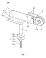
- the hinge adjuster 100 according to one embodiment of the present invention includes a first frame 1, two locking pieces 2, two spring components 3, two second frames 4, a pair of covers 5, and a connecting frame 6.
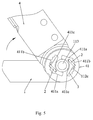
- the first frame 1 includes a sheet-shaped connecting portion 11 at its front end, a connection hole 111 is formed on the center of the connecting portion 11, and two locking holes 112 which are inverted symmetrical with the connection hole 111 are formed on the surface of the connecting portion 11.
- each locking hole 112 includes a first accommodating hole 112a and a second accommodating hole 112b which are communicated with each other.
- the first accommodating hole 112a is rectangular
- the second accommodating hole 112b is arc-shaped
- the first accommodating hole 112a is connected with the second accommodating hole 112b smoothly.
- an engaging notch 112c is formed in the inner wall of the first accommodating hole 112a.
- the first frame 1 further includes a fixture 12 at its rear end, which includes a threaded post 12a, an upper gasket 12b, a lower gasket 12c, and a nut 12d.
- a contacting edge 12e is formed between the threaded post 12a and the first frame 1, and the upper gasket 12b is set on the threaded post 12a movably and adapted for contacting with the contacting edge 12e when being at the topmost end of the threaded post 12a.
- the lower gasket 12c is set on the threaded post 12a, and the nut 12d is connected with the threaded post 12a.
- a mounting plate of the sofa When in use, a mounting plate of the sofa is provided with a through hole (not shown), the threaded post 12a passes through the through hole, and the mounting plate is sandwiched between the upper and lower gaskets 12b, 12c; and then the nut 12d is screwed on the threaded post 12a with an upper surface of the upper gasket 12b contacting with the contacting edge 12e, so that the first frame 1 is mounted on the mounting plate of the sofa, which the installation process is simple and quick.
- the locking piece 2 is slidably placed in and protruded from the first accommodating hole 112a.
- the locking piece 2 is provided with an indentation 21 at its bottom, whose width matches with the thickness of the inner wall of the first accommodating hole 112, so that the locking piece 2 can be engaged within the first accommodating hole 112a, thereby preventing two ends of the locking piece 2 from displacing. Additionally, the locking piece 2 can be engaged with the inner wall of the first accommodating hole 112a or the engaging notch 112c alternatively. As the two locking pieces 2 are received within the first accommodating holes 112a of the locking holes 112, thus force suffered by the locking pieces 2 is reduced and shared, and the force is much even.
- the spring component 3 is accommodated within the second accommodating hole 112b, one end of which is contacted with and withstood the second accommodating hole 112b, and the other end of which is contacted with one side of the locking piece 2 elastically.
- the spring component 3 is a spring leaf 3.
- the two ends of the spring leaf 3 are arc-shaped, and one end is contacted with a lower side of the locking piece 2 to push the locking piece 2 outwards elastically, so that the locking piece 2 can be maintained in the first accommodating hole 112a.
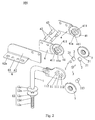
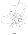
- the second frames 4 are located at opposite sides of the first frame 1 symmetrically.
- a pivoted portion 41 is provided at a front end of each second frame 4, which is shaped as a downward step and pivotally connected with the connecting portion 11 via a pin 113.
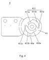
- a groove 411 is provided at the pivoted portion 41 for engaging with the locking piece 2, which includes a flat portion 411a, a dentiform portion 411b and an end portion 411c arranged in a clockwise direction.
- the locking piece 2 protrudes from one end of the locking hole 112 and contacts with the flat portion 411a, dentiform portion 411b or end portion 411c selectively.
- the amount of engaging tooth on the dentiform portion 411b can be designed according to the actual demand.
- the dentiform portion 411b is arc-shaped with an adjustable angle range of 90°, and the amount of the engaging tooth is seven, and the amount of tooth groove is six. Therefore, the adjustable angle of the second frame 4 is 90°, and the adjusted angle for each time is 15°.
- the second frame 4 is provided with two connecting pins 42 and two pin bushes 43, the connecting pins 42 pass through and firmly connect to the second frame 4 and the connecting frame 6, and the pin bushes 43 are set on the connecting pins 42. As two second frames 4 are provided in this embodiment, thus the force between the second frame 4 and the first frame 1 can be balanced, thereby enhancing the strength of the hinge adjuster 100 and extending its life.
- the connecting frame 6 is bended to form a connecting surface 61 and a supporting surface 62, and the connecting surface 61 is connected with the rear end of the second frame 4 firmly.
- the connecting frame 6 can be supported or connected to other objects, thereby adjusting the angle of the objects thereon.
- several locating holes 62a are provided at the supporting surface 62, by which the objects can be connected to the connecting frame 6 conveniently with simple and quick operation.
- the covers 5 are configured at opposite sides of the second frames 4 and covered the pivoted portion 41. Specifically, at least one protrusion 51 is extended from an edge of the cover 5, a recess 41a is formed in a brim of the pivoted portion 41 of the second frame 4, and the protrusion 51 is engaging with the recess 41a. With the arrangement of the covers 5, external substance can be prevented from falling into the groove 411 to cause the locking piece 2 fail to lock or cause the hinge adjuster 100 hard to adjust.
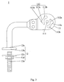
- the hinge adjuster 100 when the hinge adjuster 100 is positioned at a certain angle, the locking pieces 2 are accommodated in the first accommodating hole 112a, the indentation 21 is engaged with the inner wall of the first accommodating hole 112a, and two ends of the locking piece 2 are received in the groove 411 and engaged by one tooth groove of the dentiform portion 411b.
- the pillow of the sofa When the pillow of the sofa is supported by the second frame 4, the pillow will apply a downward force to the connecting frame 6 while enduring a force, which causes a trend that the second frame 4 to pivots closely to the first frame 1 (anticlockwise, as illustrated in Fig. 5 ).
- the pivoted portion 41 could not pivot since the dentiform portion 411b is engaging with the end of the locking piece 2, which causes the second frame 4 not to be pivotal and serve as a supporter instead.
- a handler pivots the second frame 4 clockwise to drive the pivoted portion 41, so that the dentiform portion 411b of the groove 411 is pivoted around the center axis of the pivoted portion 41.
- the locking piece 2 is pushed by one side of the present tooth groove that the locking piece 2 is engaged, so that the locking piece 2 is withdrawn from the tooth groove and compresses the spring leaf 3 simultaneously.
- the next tooth groove is driven to a position corresponding to the locking piece 2.
- the locking piece 2 is expanded to engage with the corresponding tooth groove due to the elastic restoring action of the spring leaf 3, thereby the locking piece 2 is engaging with the dentiform portion 411b again, and the second frame 4 is locked with the first frame 1 under the current angle so that it can support the pillow.
- the angle of the second frame 4 can be adjusted.
- the locking piece 2 disengages from the dentiform portion 411b, and the pivoted portion 41 is under an unlocking status (namely the second frames 4 can be folded toward the first frame 1 by pivoting anticlockwise).
- the end of the pivoted portion 41 contacts with and pushes the locking piece 2 to cause the locking piece 2 to slide to the first accommodating hole 112a and engage with the first tooth groove of the dentiform portion 411b again.
- the second frame 4 and the first frame 2 are folded completely, and the angle of the second frame 4 can be adjusted by pivoting clockwise again. In this way, the hinge adjuster 100 can be adjusted cyclically.
- the second frames 4 define the grooves 411, and the locking pieces 2 and the spring leafs 3 are mounted in the locking holes 112, thus the spring leafs 3 can be contacted with the locking pieces 2 elastically.
- the locking piece 2 is protruded from the locking hole 112 so as to cooperate with the grooves 411 at opposite sides, and the inner surface of the groove 411 includes the flat portion 411a, dentiform portion 411b and end portion 411c.
- the hinge adjuster 100 can be adjusted as long as the user pivots the second frame 4 far away from the first frame 1, and the hinge adjuster 100 is positioned at a supported status in a direction that approaches to the first frame 1.
- the hinge adjuster 100 with strong supporting capability can achieve a cyclic adjustment of angles, and the operation is simple and convenient.
Landscapes
- Engineering & Computer Science (AREA)
- Health & Medical Sciences (AREA)
- General Health & Medical Sciences (AREA)
- Dentistry (AREA)
- Aviation & Aerospace Engineering (AREA)
- Transportation (AREA)
- Mechanical Engineering (AREA)
- Nursing (AREA)
- Pivots And Pivotal Connections (AREA)
- Legs For Furniture In General (AREA)
Claims (10)
- Drehgelenkeinsteller, umfassend:einen ersten Rahmen (1) mit einem Verbindungsabschnitt (11) an einem Vorderende davon und einer Befestigung (12) an einem Rückende davon, wobei der Verbindungsabschnitt zumindest ein Arretierloch (112) definiert, das ein erstes Aufnahmeloch (112a) und ein zweites Aufnahmeloch (112b) umfasst, die miteinander in Verbindung stehen, wobei eine Eingriffskerbe (112c) in einer Innenwand des ersten Aufnahmelochs ausgebildet ist, wobei die Befestigung einen Gewindeständer (12a), eine obere Dichtung (12b), eine untere Dichtung (12c) und eine Mutter (12d) umfasst, wobei eine Kontaktkante (12e) zwischen dem Gewindeständer und dem ersten Rahmen ausgebildet ist, wobei die obere Dichtung beweglich am Gewindeständer eingerichtet ist und zum Berühren der Kontaktkante geeignet ist, wenn sie am obersten Ende des Gewindeständers ist, wobei die untere Dichtung am Gewindeständer eingerichtet ist und die Mutter am Gewindeständer angeschraubt ist;zumindest ein Arretierstück (2), das verschiebbar im ersten Aufnahmeloch angeordnet ist und daraus vorsteht und dazu geeignet ist, mit der Innenwand des ersten Aufnahmelochs oder alternativ der Eingriffskerbe in Eingriff zu treten;zumindest ein Federbauteil (3), das im zweiten Aufnahmeloch aufgenommen ist, wobei ein Ende davon elastisch mit dem zweiten Aufnahmeloch in Kontakt steht und das andere Ende davon elastisch mit einer Seite des Arretierstücks in Kontakt steht;zumindest einen zweiten Rahmen (4) mit einem Schwenkabschnitt (41) an einem Vorderende davon zum schwenkbarem Verbinden mit dem Verbindungsabschnitt des ersten Rahmens, wobei der Schwenkabschnitt zumindest eine Nut (411) zur Ineingriffnahme mit dem Arretierstück definiert, wobei eine Innenfläche der Nut einen flachen Abschnitt (411a), einen zahnförmigen Abschnitt (411b) und einen Endabschnitt umfasst, die im Uhrzeigersinn angeordnet sind, und wobei ein Abschnitt des Arretierstücks, der aus dem Arretierloch vorsteht, selektiv mit dem flachen Abschnitt, dem zahnförmigen Abschnitt oder dem Endabschnitt in Kontakt steht; undein Paar Abdeckungen (5), die auf den Verbindungsabschnitt und den Schwenkabschnitt auf gegenüberliegenden Seiten davon gedeckt sind.
- Drehgelenkeinsteller nach Anspruch 1, wobei die Anzahl der Arretierlöcher zwei ist, und wobei die zwei Arretierlöcher symmetrisch mit einer Mittelachse des Verbindungsabschnitts umgekehrt sind.
- Drehgelenkeinsteller nach Anspruch 1, wobei eine Vertiefung auf einem Boden des Arretierstücks ausgebildet ist, deren Breite mit einer Stärke der Innenwand des ersten Aufnahmelochs zusammenpasst.
- Drehgelenkeinsteller nach Anspruch 1, wobei das erste Aufnahmeloch rechteckig ist, das zweite Aufnahmeloch bogenförmig ist und das erste Aufnahmeloch glatt mit dem zweiten Aufnahmeloch verbunden ist.
- Drehgelenkeinsteller nach Anspruch 1, wobei die Anzahl der zweiten Rahmen zwei ist, und wobei die zwei zweiten Rahmen miteinander verbunden sind und auf gegenüberliegenden Seiten des ersten Rahmens symmetrisch befestigt sind.
- Drehgelenkeinsteller nach Anspruch 5, ferner umfassend einen Verbindungsrahmen, der zum Ausbilden einer Verbindungsfläche und einer Stützfläche gebogen ist, und wobei die Verbindungsfläche mit einem hinteren Ende des zweiten Rahmens verbunden ist.
- Drehgelenkeinsteller nach Anspruch 6, wobei mehrere Verbindungsstifte und Stiftbuchsen am zweiten Rahmen vorgesehen sind, wobei die Verbindungsstifte den zweiten Rahmen und den Verbindungsrahmen zum Befestigen des zweiten Rahmens am Verbindungsrahmen durchlaufen und die Stiftbuchsen jeweils an den Verbindungsstiften eingerichtet sind.
- Drehgelenkeinsteller nach Anspruch 6, wobei mehrere Lokalisierungslöcher in der Stützfläche ausgebildet sind.
- Drehgelenkeinsteller nach Anspruch 1, wobei das Federbauteil eine Blattfeder ist.
- Drehgelenkeinsteller nach Anspruch 1, wobei zumindest ein Vorsprung von einer Kante von zumindest einer der Abdeckungen verläuft, zumindest eine Aussparung in einem Rand des Schwenkabschnitts des zweiten Rahmens ausgebildet ist und der Vorsprung mit der Aussparung in Eingriff tritt.
Applications Claiming Priority (1)
| Application Number | Priority Date | Filing Date | Title |
|---|---|---|---|
| PCT/CN2012/070202 WO2013104115A1 (zh) | 2012-01-11 | 2012-01-11 | 铰链调节器 |
Publications (3)
| Publication Number | Publication Date |
|---|---|
| EP2803296A1 EP2803296A1 (de) | 2014-11-19 |
| EP2803296A4 EP2803296A4 (de) | 2015-07-29 |
| EP2803296B1 true EP2803296B1 (de) | 2016-11-02 |
Family
ID=48781029
Family Applications (1)
| Application Number | Title | Priority Date | Filing Date |
|---|---|---|---|
| EP12823233.7A Revoked EP2803296B1 (de) | 2012-01-11 | 2012-01-11 | Scharnierregler |
Country Status (5)
| Country | Link |
|---|---|
| US (1) | US8661619B2 (de) |
| EP (1) | EP2803296B1 (de) |
| BR (1) | BR112013005780A2 (de) |
| PL (1) | PL2803296T3 (de) |
| WO (1) | WO2013104115A1 (de) |
Families Citing this family (8)
| Publication number | Priority date | Publication date | Assignee | Title |
|---|---|---|---|---|
| US9199658B2 (en) * | 2012-06-22 | 2015-12-01 | Khai Gan Chuah | Baby stroller folding mechanism |
| DE102013104692B4 (de) * | 2013-05-07 | 2014-12-31 | Ferdinand Lusch Gmbh & Co. Kg | Schwenkbeschlag für Sitz- und/oder Liegemöbel |
| US9315205B2 (en) * | 2014-09-18 | 2016-04-19 | Khai Gan Chuah | Folding mechanism of baby stroller |
| US10337594B2 (en) * | 2015-01-13 | 2019-07-02 | Space Systems/Loral, Llc | Incremental deployment device |
| US9399421B2 (en) * | 2015-10-19 | 2016-07-26 | Dongguan Weihong Hardware And Plastic Products Co., Ltd. | Hinge |
| CN105662000B (zh) * | 2016-03-17 | 2018-04-03 | 东莞市伟宏五金塑胶制品有限公司 | 铰链安装插套 |
| US10822045B1 (en) * | 2020-04-02 | 2020-11-03 | King Roof Industrial Co., Ltd. | Pivoting mechanism and carrier positioning device including the same |
| CN118953182B (zh) * | 2024-10-17 | 2024-12-17 | 长春富晟李尔汽车座椅系统有限公司 | 一种侧扶手角度调节机构及可调节角度的座椅侧扶手 |
Citations (3)
| Publication number | Priority date | Publication date | Assignee | Title |
|---|---|---|---|---|
| US20100293748A1 (en) | 2009-05-22 | 2010-11-25 | Koyo Giken Kabushiki Kaisya | Angle-adjustable hinge |
| CN201870189U (zh) | 2010-10-29 | 2011-06-22 | 卢伟 | 沙发头枕调节器 |
| PL216240B1 (pl) | 2009-06-15 | 2014-03-31 | Okuć Meblowych Stalmot Społka Z Ograniczoną Odpowiedzialnością Fab | Mechanizm przegubowy |
Family Cites Families (14)
| Publication number | Priority date | Publication date | Assignee | Title |
|---|---|---|---|---|
| GB2023710A (en) * | 1977-10-18 | 1980-01-03 | Uop Inc | Locking seat hinges |
| US5123768A (en) * | 1991-08-06 | 1992-06-23 | Franklin Ronald D | Articulating positioning device for tools |
| JPH1028624A (ja) * | 1996-07-17 | 1998-02-03 | Araco Corp | 座椅子等の角度調節機構 |
| JP3436501B2 (ja) * | 1999-02-03 | 2003-08-11 | 向陽技研株式会社 | 角度調整具 |
| DE29907520U1 (de) * | 1999-04-28 | 1999-09-09 | Franke GmbH & Co KG, 72336 Balingen | Gelenkbeschlag |
| US6869144B2 (en) * | 2000-10-12 | 2005-03-22 | Atl Engineering (Uk) Limited | Pivot mechanism |
| US6711780B2 (en) * | 2001-08-22 | 2004-03-30 | Sinclair Worldwide, Inc. | Hinge for collapsible ladders |
| US6804845B2 (en) * | 2001-12-21 | 2004-10-19 | The Ideal People Llc | Adjustable body support cushions |
| DE10254122A1 (de) * | 2002-11-20 | 2004-06-17 | Cimosys Ag | Elektromotorischer Möbelantrieb zum Verstellen von Teilen eines Möbels relativ zueinander |
| JP3766669B2 (ja) * | 2003-08-29 | 2006-04-12 | 直伸 山下 | 角度調整金具 |
| US7052089B2 (en) * | 2003-10-14 | 2006-05-30 | Lane Furniture Industries, Inc. | Multi-position headrest and mechanism therefor |
| CN2774290Y (zh) * | 2005-01-02 | 2006-04-26 | 谭耀珠 | 一种靠背头枕调节器 |
| GB2436121A (en) * | 2006-03-16 | 2007-09-19 | Atl Engineering | Seat reclining means with sliding ratchet lock |
| JP4296223B1 (ja) * | 2008-05-23 | 2009-07-15 | 直伸 山下 | 角度調整金具 |
-
2012
- 2012-01-11 BR BR112013005780A patent/BR112013005780A2/pt not_active Application Discontinuation
- 2012-01-11 PL PL12823233T patent/PL2803296T3/pl unknown
- 2012-01-11 WO PCT/CN2012/070202 patent/WO2013104115A1/zh not_active Ceased
- 2012-01-11 EP EP12823233.7A patent/EP2803296B1/de not_active Revoked
- 2012-01-11 US US13/813,931 patent/US8661619B2/en active Active
Patent Citations (3)
| Publication number | Priority date | Publication date | Assignee | Title |
|---|---|---|---|---|
| US20100293748A1 (en) | 2009-05-22 | 2010-11-25 | Koyo Giken Kabushiki Kaisya | Angle-adjustable hinge |
| PL216240B1 (pl) | 2009-06-15 | 2014-03-31 | Okuć Meblowych Stalmot Społka Z Ograniczoną Odpowiedzialnością Fab | Mechanizm przegubowy |
| CN201870189U (zh) | 2010-10-29 | 2011-06-22 | 卢伟 | 沙发头枕调节器 |
Non-Patent Citations (5)
| Title |
|---|
| ANONYMOUS: "Regulacja kata nawet najmniejszych zaglówtów /Partial English translation enclosed/", TAPICER PISMO PRODUCENTÓW / TAPICER MANUFACTURERS MAGAZINE/, vol. 2, no. 6, 2011, pages 10, XP055404862 |
| FABRYKA OKUĆ MEBLOWYCH STALMOT S. A., WOLSZTYŃSKA FABRYKA OKUĆ WOLMET SP. Z O.O., STALMOT WOLMET KATALOG 2011, 2011, pages 47 - 48, XP055404869 |
| HETTICH FRANKE GMBH & CO. KG: "Beschläge für Polstermöbel Flexibel bleiben- in allen Lagen / Fittings for upholstered furniture Be flexible - in all positions", HETTICH CATALOGUE, 2011, pages 1 - 34, XP055404842, Retrieved from the Internet <URL:https://www.hettich.com/fileadmin/content/documents/fittings_for_upholstered_furniture_2010_de_en.pdf> |
| HETTICHENGLISH: "Hettich VarioFlex with round link: adjustable fitting for neck sections in upholstered furniture", YOUTUBE, 19 October 2011 (2011-10-19), XP054977712, Retrieved from the Internet <URL:https://www.youtube.com/watch?v=SnrwHv8ARkA> |
| TORNAGHI OFFICINA MECCANICA: "Meccanismo Poggiatesta", INTERNET ARCHIVE WAYBACK MACHINE, 7 December 2010 (2010-12-07), XP055404872, Retrieved from the Internet <URL:https://web.archive.org/web/20101207114453/http://www.tornaghi.it:80/it/poggia.htm> |
Also Published As
| Publication number | Publication date |
|---|---|
| WO2013104115A1 (zh) | 2013-07-18 |
| PL2803296T3 (pl) | 2017-09-29 |
| US20130333161A1 (en) | 2013-12-19 |
| EP2803296A4 (de) | 2015-07-29 |
| EP2803296A1 (de) | 2014-11-19 |
| US8661619B2 (en) | 2014-03-04 |
| BR112013005780A2 (pt) | 2017-11-14 |
Similar Documents
| Publication | Publication Date | Title |
|---|---|---|
| EP2803296B1 (de) | Scharnierregler | |
| US9291299B2 (en) | Display stand with latching mechanism | |
| US7047597B2 (en) | Hinge for folding ladders | |
| US9341010B2 (en) | Furniture door position adjustment device for furniture hinge | |
| EP3443436B1 (de) | Vorrichtung mit einer drehbaren anzeige | |
| EP2876504B1 (de) | Schraubenloser Spiralklötzchen-Träger für Uhr | |
| CN102890542B (zh) | 夹持装置及具有该夹持装置的外接键盘 | |
| CN101227846A (zh) | 定位配件 | |
| US20090031531A1 (en) | Arresting Device for Hinge Assembly Structure | |
| US20070241603A1 (en) | Armrest Locking Mechanism | |
| US20190084817A1 (en) | Pivoting prybar head | |
| KR101593116B1 (ko) | 의자 등받이 틸팅장치 | |
| PL72857Y1 (pl) | Układ wsporczy dla zagłówka | |
| GB2438662A (en) | Adjustable holder for an electronic device | |
| KR101207295B1 (ko) | 독서대 받침대 | |
| CN204427324U (zh) | 档位升降架 | |
| TW201430481A (zh) | 原稿壓合板開闔裝置及事務機器 | |
| US10917981B2 (en) | Adjustable embedded display unit backframe | |
| JP5866647B2 (ja) | ペーパーホルダーの取付構造 | |
| KR102035144B1 (ko) | 의자 | |
| AU2021385694A1 (en) | Safety seat | |
| JP3017919B2 (ja) | 椅子の肘掛け上下位置調節装置 | |
| JP4387805B2 (ja) | 椅子の肘掛け装置 | |
| EP2727496A1 (de) | Ratschenvorrichtung | |
| CN219742236U (zh) | 座椅 |
Legal Events
| Date | Code | Title | Description |
|---|---|---|---|
| PUAI | Public reference made under article 153(3) epc to a published international application that has entered the european phase |
Free format text: ORIGINAL CODE: 0009012 |
|
| 17P | Request for examination filed |
Effective date: 20130314 |
|
| AK | Designated contracting states |
Kind code of ref document: A1 Designated state(s): AL AT BE BG CH CY CZ DE DK EE ES FI FR GB GR HR HU IE IS IT LI LT LU LV MC MK MT NL NO PL PT RO RS SE SI SK SM TR |
|
| DAX | Request for extension of the european patent (deleted) | ||
| RA4 | Supplementary search report drawn up and despatched (corrected) |
Effective date: 20150701 |
|
| RIC1 | Information provided on ipc code assigned before grant |
Ipc: A47C 20/04 20060101AFI20150625BHEP Ipc: A47C 1/026 20060101ALI20150625BHEP |
|
| RIC1 | Information provided on ipc code assigned before grant |
Ipc: A47C 1/026 20060101ALI20160419BHEP Ipc: A47C 20/04 20060101AFI20160419BHEP |
|
| GRAP | Despatch of communication of intention to grant a patent |
Free format text: ORIGINAL CODE: EPIDOSNIGR1 |
|
| INTG | Intention to grant announced |
Effective date: 20160624 |
|
| GRAS | Grant fee paid |
Free format text: ORIGINAL CODE: EPIDOSNIGR3 |
|
| GRAA | (expected) grant |
Free format text: ORIGINAL CODE: 0009210 |
|
| AK | Designated contracting states |
Kind code of ref document: B1 Designated state(s): AL AT BE BG CH CY CZ DE DK EE ES FI FR GB GR HR HU IE IS IT LI LT LU LV MC MK MT NL NO PL PT RO RS SE SI SK SM TR |
|
| REG | Reference to a national code |
Ref country code: GB Ref legal event code: FG4D |
|
| REG | Reference to a national code |
Ref country code: RO Ref legal event code: EPE |
|
| REG | Reference to a national code |
Ref country code: AT Ref legal event code: REF Ref document number: 840916 Country of ref document: AT Kind code of ref document: T Effective date: 20161115 Ref country code: CH Ref legal event code: EP |
|
| REG | Reference to a national code |
Ref country code: IE Ref legal event code: FG4D |
|
| REG | Reference to a national code |
Ref country code: DE Ref legal event code: R096 Ref document number: 602012024970 Country of ref document: DE |
|
| REG | Reference to a national code |
Ref country code: FR Ref legal event code: PLFP Year of fee payment: 6 |
|
| PG25 | Lapsed in a contracting state [announced via postgrant information from national office to epo] |
Ref country code: LV Free format text: LAPSE BECAUSE OF FAILURE TO SUBMIT A TRANSLATION OF THE DESCRIPTION OR TO PAY THE FEE WITHIN THE PRESCRIBED TIME-LIMIT Effective date: 20161102 |
|
| REG | Reference to a national code |
Ref country code: NL Ref legal event code: MP Effective date: 20161102 |
|
| REG | Reference to a national code |
Ref country code: LT Ref legal event code: MG4D |
|
| REG | Reference to a national code |
Ref country code: AT Ref legal event code: MK05 Ref document number: 840916 Country of ref document: AT Kind code of ref document: T Effective date: 20161102 |
|
| PG25 | Lapsed in a contracting state [announced via postgrant information from national office to epo] |
Ref country code: LT Free format text: LAPSE BECAUSE OF FAILURE TO SUBMIT A TRANSLATION OF THE DESCRIPTION OR TO PAY THE FEE WITHIN THE PRESCRIBED TIME-LIMIT Effective date: 20161102 Ref country code: GR Free format text: LAPSE BECAUSE OF FAILURE TO SUBMIT A TRANSLATION OF THE DESCRIPTION OR TO PAY THE FEE WITHIN THE PRESCRIBED TIME-LIMIT Effective date: 20170203 Ref country code: NO Free format text: LAPSE BECAUSE OF FAILURE TO SUBMIT A TRANSLATION OF THE DESCRIPTION OR TO PAY THE FEE WITHIN THE PRESCRIBED TIME-LIMIT Effective date: 20170202 Ref country code: SE Free format text: LAPSE BECAUSE OF FAILURE TO SUBMIT A TRANSLATION OF THE DESCRIPTION OR TO PAY THE FEE WITHIN THE PRESCRIBED TIME-LIMIT Effective date: 20161102 Ref country code: NL Free format text: LAPSE BECAUSE OF FAILURE TO SUBMIT A TRANSLATION OF THE DESCRIPTION OR TO PAY THE FEE WITHIN THE PRESCRIBED TIME-LIMIT Effective date: 20161102 |
|
| PG25 | Lapsed in a contracting state [announced via postgrant information from national office to epo] |
Ref country code: HR Free format text: LAPSE BECAUSE OF FAILURE TO SUBMIT A TRANSLATION OF THE DESCRIPTION OR TO PAY THE FEE WITHIN THE PRESCRIBED TIME-LIMIT Effective date: 20161102 Ref country code: ES Free format text: LAPSE BECAUSE OF FAILURE TO SUBMIT A TRANSLATION OF THE DESCRIPTION OR TO PAY THE FEE WITHIN THE PRESCRIBED TIME-LIMIT Effective date: 20161102 Ref country code: PT Free format text: LAPSE BECAUSE OF FAILURE TO SUBMIT A TRANSLATION OF THE DESCRIPTION OR TO PAY THE FEE WITHIN THE PRESCRIBED TIME-LIMIT Effective date: 20170302 Ref country code: IS Free format text: LAPSE BECAUSE OF FAILURE TO SUBMIT A TRANSLATION OF THE DESCRIPTION OR TO PAY THE FEE WITHIN THE PRESCRIBED TIME-LIMIT Effective date: 20170302 Ref country code: BE Free format text: LAPSE BECAUSE OF NON-PAYMENT OF DUE FEES Effective date: 20170131 Ref country code: AT Free format text: LAPSE BECAUSE OF FAILURE TO SUBMIT A TRANSLATION OF THE DESCRIPTION OR TO PAY THE FEE WITHIN THE PRESCRIBED TIME-LIMIT Effective date: 20161102 Ref country code: RS Free format text: LAPSE BECAUSE OF FAILURE TO SUBMIT A TRANSLATION OF THE DESCRIPTION OR TO PAY THE FEE WITHIN THE PRESCRIBED TIME-LIMIT Effective date: 20161102 Ref country code: FI Free format text: LAPSE BECAUSE OF FAILURE TO SUBMIT A TRANSLATION OF THE DESCRIPTION OR TO PAY THE FEE WITHIN THE PRESCRIBED TIME-LIMIT Effective date: 20161102 |
|
| REG | Reference to a national code |
Ref country code: DE Ref legal event code: R026 Ref document number: 602012024970 Country of ref document: DE |
|
| PG25 | Lapsed in a contracting state [announced via postgrant information from national office to epo] |
Ref country code: EE Free format text: LAPSE BECAUSE OF FAILURE TO SUBMIT A TRANSLATION OF THE DESCRIPTION OR TO PAY THE FEE WITHIN THE PRESCRIBED TIME-LIMIT Effective date: 20161102 Ref country code: CZ Free format text: LAPSE BECAUSE OF FAILURE TO SUBMIT A TRANSLATION OF THE DESCRIPTION OR TO PAY THE FEE WITHIN THE PRESCRIBED TIME-LIMIT Effective date: 20161102 Ref country code: DK Free format text: LAPSE BECAUSE OF FAILURE TO SUBMIT A TRANSLATION OF THE DESCRIPTION OR TO PAY THE FEE WITHIN THE PRESCRIBED TIME-LIMIT Effective date: 20161102 Ref country code: SK Free format text: LAPSE BECAUSE OF FAILURE TO SUBMIT A TRANSLATION OF THE DESCRIPTION OR TO PAY THE FEE WITHIN THE PRESCRIBED TIME-LIMIT Effective date: 20161102 |
|
| PLBI | Opposition filed |
Free format text: ORIGINAL CODE: 0009260 |
|
| PG25 | Lapsed in a contracting state [announced via postgrant information from national office to epo] |
Ref country code: BE Free format text: LAPSE BECAUSE OF FAILURE TO SUBMIT A TRANSLATION OF THE DESCRIPTION OR TO PAY THE FEE WITHIN THE PRESCRIBED TIME-LIMIT Effective date: 20161102 Ref country code: BG Free format text: LAPSE BECAUSE OF FAILURE TO SUBMIT A TRANSLATION OF THE DESCRIPTION OR TO PAY THE FEE WITHIN THE PRESCRIBED TIME-LIMIT Effective date: 20170202 Ref country code: SM Free format text: LAPSE BECAUSE OF FAILURE TO SUBMIT A TRANSLATION OF THE DESCRIPTION OR TO PAY THE FEE WITHIN THE PRESCRIBED TIME-LIMIT Effective date: 20161102 |
|
| REG | Reference to a national code |
Ref country code: CH Ref legal event code: PL |
|
| 26 | Opposition filed |
Opponent name: ANMART S.J. SLUSAREK I SPOLKA Effective date: 20170725 |
|
| PLAX | Notice of opposition and request to file observation + time limit sent |
Free format text: ORIGINAL CODE: EPIDOSNOBS2 |
|
| PG25 | Lapsed in a contracting state [announced via postgrant information from national office to epo] |
Ref country code: MC Free format text: LAPSE BECAUSE OF FAILURE TO SUBMIT A TRANSLATION OF THE DESCRIPTION OR TO PAY THE FEE WITHIN THE PRESCRIBED TIME-LIMIT Effective date: 20161102 |
|
| GBPC | Gb: european patent ceased through non-payment of renewal fee |
Effective date: 20170202 |
|
| PG25 | Lapsed in a contracting state [announced via postgrant information from national office to epo] |
Ref country code: CH Free format text: LAPSE BECAUSE OF NON-PAYMENT OF DUE FEES Effective date: 20170131 Ref country code: LI Free format text: LAPSE BECAUSE OF NON-PAYMENT OF DUE FEES Effective date: 20170131 |
|
| REG | Reference to a national code |
Ref country code: IE Ref legal event code: MM4A |
|
| PG25 | Lapsed in a contracting state [announced via postgrant information from national office to epo] |
Ref country code: LU Free format text: LAPSE BECAUSE OF NON-PAYMENT OF DUE FEES Effective date: 20170111 Ref country code: SI Free format text: LAPSE BECAUSE OF FAILURE TO SUBMIT A TRANSLATION OF THE DESCRIPTION OR TO PAY THE FEE WITHIN THE PRESCRIBED TIME-LIMIT Effective date: 20161102 |
|
| REG | Reference to a national code |
Ref country code: FR Ref legal event code: PLFP Year of fee payment: 7 |
|
| PLBB | Reply of patent proprietor to notice(s) of opposition received |
Free format text: ORIGINAL CODE: EPIDOSNOBS3 |
|
| PG25 | Lapsed in a contracting state [announced via postgrant information from national office to epo] |
Ref country code: IE Free format text: LAPSE BECAUSE OF NON-PAYMENT OF DUE FEES Effective date: 20170111 Ref country code: GB Free format text: LAPSE BECAUSE OF NON-PAYMENT OF DUE FEES Effective date: 20170202 |
|
| PGFP | Annual fee paid to national office [announced via postgrant information from national office to epo] |
Ref country code: PL Payment date: 20171124 Year of fee payment: 7 |
|
| PGFP | Annual fee paid to national office [announced via postgrant information from national office to epo] |
Ref country code: RO Payment date: 20180103 Year of fee payment: 7 Ref country code: DE Payment date: 20171128 Year of fee payment: 7 |
|
| PGFP | Annual fee paid to national office [announced via postgrant information from national office to epo] |
Ref country code: FR Payment date: 20180124 Year of fee payment: 7 Ref country code: IT Payment date: 20180126 Year of fee payment: 7 |
|
| RDAF | Communication despatched that patent is revoked |
Free format text: ORIGINAL CODE: EPIDOSNREV1 |
|
| STAA | Information on the status of an ep patent application or granted ep patent |
Free format text: STATUS: THE PATENT HAS BEEN GRANTED |
|
| REG | Reference to a national code |
Ref country code: DE Ref legal event code: R064 Ref document number: 602012024970 Country of ref document: DE Ref country code: DE Ref legal event code: R103 Ref document number: 602012024970 Country of ref document: DE |
|
| PG25 | Lapsed in a contracting state [announced via postgrant information from national office to epo] |
Ref country code: MT Free format text: LAPSE BECAUSE OF NON-PAYMENT OF DUE FEES Effective date: 20170111 |
|
| RDAG | Patent revoked |
Free format text: ORIGINAL CODE: 0009271 |
|
| STAA | Information on the status of an ep patent application or granted ep patent |
Free format text: STATUS: PATENT REVOKED |
|
| 27W | Patent revoked |
Effective date: 20180625 |
|
| PG25 | Lapsed in a contracting state [announced via postgrant information from national office to epo] |
Ref country code: MK Free format text: LAPSE BECAUSE OF FAILURE TO SUBMIT A TRANSLATION OF THE DESCRIPTION OR TO PAY THE FEE WITHIN THE PRESCRIBED TIME-LIMIT Effective date: 20161102 |
|
| PG25 | Lapsed in a contracting state [announced via postgrant information from national office to epo] |
Ref country code: CY Free format text: LAPSE BECAUSE OF FAILURE TO SUBMIT A TRANSLATION OF THE DESCRIPTION OR TO PAY THE FEE WITHIN THE PRESCRIBED TIME-LIMIT Effective date: 20161102 |
|
| PG25 | Lapsed in a contracting state [announced via postgrant information from national office to epo] |
Ref country code: AL Free format text: LAPSE BECAUSE OF FAILURE TO SUBMIT A TRANSLATION OF THE DESCRIPTION OR TO PAY THE FEE WITHIN THE PRESCRIBED TIME-LIMIT Effective date: 20161102 |
|
| PG25 | Lapsed in a contracting state [announced via postgrant information from national office to epo] |
Ref country code: TR Free format text: LAPSE BECAUSE OF FAILURE TO SUBMIT A TRANSLATION OF THE DESCRIPTION OR TO PAY THE FEE WITHIN THE PRESCRIBED TIME-LIMIT Effective date: 20161102 |