EP2802409B1 - Systeme d'agitation ou de conservation de peintures - Google Patents
Systeme d'agitation ou de conservation de peintures Download PDFInfo
- Publication number
- EP2802409B1 EP2802409B1 EP12787390.9A EP12787390A EP2802409B1 EP 2802409 B1 EP2802409 B1 EP 2802409B1 EP 12787390 A EP12787390 A EP 12787390A EP 2802409 B1 EP2802409 B1 EP 2802409B1
- Authority
- EP
- European Patent Office
- Prior art keywords
- cylindrical
- cylindrical rollers
- belt
- rollers
- container
- Prior art date
- Legal status (The legal status is an assumption and is not a legal conclusion. Google has not performed a legal analysis and makes no representation as to the accuracy of the status listed.)
- Not-in-force
Links
- 239000003973 paint Substances 0.000 title claims description 22
- 238000003756 stirring Methods 0.000 title claims description 14
- 239000000463 material Substances 0.000 claims description 6
- 230000002093 peripheral effect Effects 0.000 claims description 5
- 230000002035 prolonged effect Effects 0.000 claims 1
- 239000003086 colorant Substances 0.000 description 8
- 238000013019 agitation Methods 0.000 description 6
- 239000000049 pigment Substances 0.000 description 4
- 239000000203 mixture Substances 0.000 description 3
- 239000011230 binding agent Substances 0.000 description 2
- 230000000694 effects Effects 0.000 description 2
- 239000000839 emulsion Substances 0.000 description 2
- 238000000265 homogenisation Methods 0.000 description 2
- 230000000149 penetrating effect Effects 0.000 description 2
- 238000004321 preservation Methods 0.000 description 2
- 230000001603 reducing effect Effects 0.000 description 2
- 230000002441 reversible effect Effects 0.000 description 2
- 239000002904 solvent Substances 0.000 description 2
- 239000000654 additive Substances 0.000 description 1
- 230000032683 aging Effects 0.000 description 1
- 238000003556 assay Methods 0.000 description 1
- 230000000712 assembly Effects 0.000 description 1
- 238000000429 assembly Methods 0.000 description 1
- 230000005540 biological transmission Effects 0.000 description 1
- 238000006073 displacement reaction Methods 0.000 description 1
- 238000009472 formulation Methods 0.000 description 1
- 230000009347 mechanical transmission Effects 0.000 description 1
- 238000000034 method Methods 0.000 description 1
- 238000010422 painting Methods 0.000 description 1
- 230000000750 progressive effect Effects 0.000 description 1
- 239000011347 resin Substances 0.000 description 1
- 229920005989 resin Polymers 0.000 description 1
- 230000000284 resting effect Effects 0.000 description 1
- 239000000126 substance Substances 0.000 description 1
- 230000001360 synchronised effect Effects 0.000 description 1
- 230000009974 thixotropic effect Effects 0.000 description 1
- 239000002966 varnish Substances 0.000 description 1
- 238000005303 weighing Methods 0.000 description 1
Images


Classifications
-
- B—PERFORMING OPERATIONS; TRANSPORTING
- B01—PHYSICAL OR CHEMICAL PROCESSES OR APPARATUS IN GENERAL
- B01F—MIXING, e.g. DISSOLVING, EMULSIFYING OR DISPERSING
- B01F29/00—Mixers with rotating receptacles
- B01F29/30—Mixing the contents of individual packages or containers, e.g. by rotating tins or bottles
- B01F29/31—Mixing the contents of individual packages or containers, e.g. by rotating tins or bottles the containers being supported by driving means, e.g. by rotating rollers
-
- B—PERFORMING OPERATIONS; TRANSPORTING
- B01—PHYSICAL OR CHEMICAL PROCESSES OR APPARATUS IN GENERAL
- B01F—MIXING, e.g. DISSOLVING, EMULSIFYING OR DISPERSING
- B01F23/00—Mixing according to the phases to be mixed, e.g. dispersing or emulsifying
- B01F23/50—Mixing liquids with solids
- B01F23/53—Mixing liquids with solids using driven stirrers
-
- B—PERFORMING OPERATIONS; TRANSPORTING
- B44—DECORATIVE ARTS
- B44D—PAINTING OR ARTISTIC DRAWING, NOT OTHERWISE PROVIDED FOR; PRESERVING PAINTINGS; SURFACE TREATMENT TO OBTAIN SPECIAL ARTISTIC SURFACE EFFECTS OR FINISHES
- B44D3/00—Accessories or implements for use in connection with painting or artistic drawing, not otherwise provided for; Methods or devices for colour determination, selection, or synthesis, e.g. use of colour tables
- B44D3/06—Implements for stirring or mixing paints
-
- B—PERFORMING OPERATIONS; TRANSPORTING
- B01—PHYSICAL OR CHEMICAL PROCESSES OR APPARATUS IN GENERAL
- B01F—MIXING, e.g. DISSOLVING, EMULSIFYING OR DISPERSING
- B01F2101/00—Mixing characterised by the nature of the mixed materials or by the application field
- B01F2101/30—Mixing paints or paint ingredients, e.g. pigments, dyes, colours, lacquers or enamel
Definitions
- the present invention relates to the field of painting, particularly for automobiles.
- the present invention relates more particularly to a system for stirring or preserving paint mixtures for the automobile.
- Automotive body repair requires the application of paint in the final phase.
- the hue applied must be identical to the original color or the actual color at the time of repair.
- Each repair does not necessarily involve repainting the entire vehicle.
- An appropriate formulation possibly corrected according to a coloristic measure or the painter's know-how, will be defined to repaint the vehicle.
- the base of the hundred thousand formulas currently achievable can be recomposed using 40 to 150 base shades of a paint line from a manufacturer.
- the realization of a formula is carried out using 3 to 10 basic colors, the average being 5 shades of base.
- Base colors are a mixture of pigments, varnishes and binders, such as resins, solvents and additives.
- a precise dosage on the order of 0.05 g, but also a perfect homogenization of colored pigments in the binder. Therefore, it is necessary to proceed with the agitation of the basic colors before use to ensure excellent reproduction of their coloristic powers. Indeed, it is accepted that a set of well homogenized base shades allows a correct recomposition of the hue to achieve.
- the object of the present invention is to overcome one or more disadvantages of the prior art by providing an economical, silent and efficient paint agitation or conservation system.
- an agitation or paint conservation system contained in at least one cylindrical container, characterized in that it comprises at least one series of cylindrical rollers regularly aligned on at least one support, the cylindrical rollers having axes parallel to each other and inclined, at least one roller cylinder on two adjacent rollers cylinders being rotated about its axis by a drive system, the distance between two adjacent cylindrical rollers being less than or equal to the diameter of a cylindrical container so that the cylindrical surface of the container can rest on the cylindrical surface of two adjacent cylindrical rollers, the stirring system further comprising at least one lid adapted to seal the cylindrical container (s), the lid being provided with at least one removable blade penetrating into the cylindrical container when the container is closed by lid.
- the drive system comprises a driving pulley driving a belt, the drive system further comprising a plurality of pulleys integral with the cylindrical rollers driven by the belt, the belt being alternately arranged on one side right of a first pulley of a cylindrical roller and then a left side of a second pulley of the adjacent cylindrical roller by considering the driving direction of the belt, each of the pulleys associated with a cylindrical roller being followed and / or preceded by a cylindrical roller pulley leaving crazy in rotation its associated cylindrical roller.
- the drive system comprises a driving pulley driving a belt, the drive system further comprising a plurality of pulleys integral with the cylindrical rollers driven by the belt and a plurality of intermediate pulleys arranged between two pulleys integral with the cylindrical rollers, the belt being alternately arranged on a right side of a pulley of a cylindrical roller and then on a left side of an intermediate pulley adjacent considering the driving direction of the belt, each of the cylindrical roller pulleys driving its associated cylindrical roller.
- the drive pulley is driven by a motor, the drive pulley having a vertical axis of rotation, the movement transmitted by the belt by the drive pulley being transmitted to the cylindrical roller pulleys through at least one return pulley.
- the belt is a circular section belt.
- each support supporting a series of cylindrical rollers are arranged one above the other, the space between each support allowing at least the passage of a container so that the container can be deposited on two adjacent cylindrical rollers, the supports being mounted in the form of removable shelves held by common amounts, a shaft transmitting the rotation of the motor to the drive pulleys of each support.
- the distance between two adjacent cylindrical rollers of a first series of cylindrical rollers is different from the distance between two adjacent cylindrical rollers of a second series of cylindrical rollers.
- the motor is an electric motor transmitting a variable speed of rotation to the drive pulley.
- the axes of the cylindrical rollers are inclined at an angle of between 20 ° and 60 ° with respect to a vertical axis.
- the axes of the cylindrical rollers are inclined by 45 ° with respect to a vertical axis.
- the cylindrical rollers have a cylindrical surface covered with a gripping material.
- the one or more supports have a V-shaped section with a 90 ° angle, the V-shaped section defining a part of the support intended to receive the cylindrical rollers, a branch of the V being extended by a straight line. horizontal, the horizontal line defining a portion of the support on which is fixed the drive pulley.
- the cylindrical rollers comprise two cylindrical portions, a first cylindrical portion intended to receive at least the peripheral surface of the cover with a diameter smaller than the diameter of the second cylindrical portion intended to receive at least a portion of the cylindrical surface of the container on which the lid is fitted.
- the lid further comprises a variable flow spout system controlled by a slide brought into the closed position by elastic means and whose open position is defined by a handle rotatably mounted on the cover and solidary moving with the slide by a linkage.
- the lid further comprises a handle handle.
- the invention relates to a system (0) for agitating or preserving paint contained in at least one cylindrical container (1).
- a cylindrical container (1) may be a pot or bottle containing paint, one or more basic colors.
- Agitation or preservation is similar to maintaining the original homogeneity of the color pigments rather than resuspending by stirring these pigments.
- the effect of this preservation will also have a reducing effect on the hardening during the period of use.
- the system (4) comprises at least one series (2x1; 2x2) of rollers (2a1, 2b1, 2a2, 2b2) cylindrical regularly aligned on at least one support (31, 32).
- the cylindrical rollers (2a1, 2b1; 2a2, 2b2) have axes parallel to each other.
- These cylindrical rollers (2a1, 2b1, 2a2, 2b2) are inclined with respect to a vertical axis (12) of an angle a.
- this angle (a) is between 20 ° and 60 °, preferably 45 °.
- the inclined position allows a better circulation of the paint in the containers when the containers rotate. It also improves the ergonomic conditions for handling containers.
- At least one cylindrical roller (2a1, 2a2) on two adjacent cylindrical rollers (2a1, 2b1, 2a2, 2b2) is rotated about its axis (11) by a drive system (4).
- the distance (d1, d2) between two adjacent cylindrical rollers (2a1, 2b1, 2a2, 2b2) is less than or equal to the diameter of a cylindrical container (1) so that the cylindrical surface of the container can rest on the cylindrical surface of two adjacent cylindrical rollers (2a1, 2b1, 2a2, 2b2).
- the rollers (2a1, 2b1, 2a2, 2b2) cylindrical can transmit their rotation to the containers resting on them
- the rollers (2a1, 2b1, 2a2, 2b2) cylindrical have a cylindrical surface covered with a gripping or non-slip material .
- the gripping material may be rubber or any other material which grips the cylindrical surface of a cylindrical container so that the driven cylindrical rollers transmit their rotation to the container (s).
- the rotational speed transmitted by the cylindrical rollers is constant regardless of the diameter of the cylindrical containers.
- the speed of rotation transmitted by the cylindrical rollers is of the order of 3 rpm at 15 rpm.
- the diameter of the cylindrical rollers (2a1, 2b1, 2a2, 2b2) can be chosen according to the speed of rotation that is to be transmitted to the cylindrical containers.
- the larger the diameter of the cylindrical rollers the greater the rotational speed of the cylindrical container (s) transmitted by the cylindrical rollers is important.
- the stirring system (0) further comprises at least one lid (5) adapted to seal the cylindrical container (s) (1).
- Closing the lid (5) on the container or containers (1) can be done by clipping, screwing or other means of fixing the lid on the container.
- the lid (7) is provided with clamping means on the lid body which are clipped to the interlocking crown of the container to be covered.
- the clamping means comprise two elastic fingers automatically bearing against the annular surface of the crown when the body of the lid is positioned on the container.
- the lid (5) is provided with at least one blade (6) penetrating into the cylindrical container (1) when the container (1) is closed by the lid (5).
- the blade (6) is fixed to the center of the lid (5).
- the blade (6) has a length substantially equal to the depth of the cylindrical container (1). This blade (6) improves the agitation of my paint in the container (1) during the rotation of the container (1).
- the blade (6) can be removable by clipping onto the lid, for example.
- the blade (6) can form a one-piece assembly with the lid (5).
- the lid (5) further comprises a variable flow pourer spout system (10).
- the variable flow spout system includes an outlet port, a flattened closure member (101) for closing the port and means (102) for driving the translational closure member (101). in said opening plane.
- the drive means (102) include a pull rod connected by fastening means (103) to the closure element and comprising an end portion secured to a push means (104) driving said rod in the direction of the opening.
- the spout system (10) pouring variable flow is controlled by a slide brought into the closed position by elastic means and whose open position is defined by a handle rotatably mounted on the cover and integral in displacement with the slide by a linkage.
- the lid (7) further comprises a handle (11) gripping for grasping the lid (7) alone or to grasp the lid (7) with the container attached to the lid (7).
- This handle handle (11) also facilitates the pouring of the paint contained in the container. It also makes it easy to handle the spout system (10).
- the lid (5) may have a cylindrical peripheral surface whose diameter is greater than the diameter of the cylindrical container (1) on which the lid (1) is adapted.
- the cylindrical rollers (2a1, 2b1, 2a2, 2b2) comprise two cylindrical portions (200, 201).
- the difference in diameter of the two cylindrical parts of a cylindrical roller is, for example, equal to the difference between the diameter of the peripheral surface of the lid (5) and the diameter of the cylindrical surface of the container (1).
- the first portion (200) of a roller can be connected to the second portion (201) of the roller by a frustoconical portion (202).
- the base of the frustoconical portion (202) has a surface that may be equal to the cross sectional area of the second portion (201).
- the top of the frusto-conical portion (202) has a surface that may be equal to the cross-sectional area of the first portion (200).
- the surface of the rollers can be removable to change the dimensions of the first cylindrical portion and the second cylindrical portion of the roller.
- the drive system (4) comprises a driving pulley (6) driving a belt (7).
- the drive system (4) further comprises a plurality of pulleys (3a1, 3a2) integral with the cylindrical rollers driven by the belt (7).
- the belt (7) is alternately arranged on a right side of a first pulley (3a1) of a cylindrical roller then a left side of a second pulley (3a2) of the adjacent cylindrical roller.
- Each of the pulleys (3a1, 3b1) associated with a roller (2a1, 2b1) cylindrical is followed and / or preceded by a pulley (3b2) of cylindrical roller leaving crazy in rotation its roller (2b1) associated cylindrical.
- the drive system (4) comprises a driving pulley (6) driving a belt (7).
- the drive system (4) further comprises a plurality of pulleys (3a1) integral with the cylindrical rollers driven by the belt (7) and a plurality of intermediate pulleys (4a1) disposed between two pulleys (3a1) integral with the cylindrical rollers.
- the belt (7) is alternately arranged on a right side of a pulley of a roller roller and then on a left side of a pulley (4a1) adjacent intermediate.
- Each of the cylinder pulleys (3a1) is associated with a cylindrical roller and drives its cylindrical roller associated.
- the intermediate pulleys (4a1) are used to tension the belt (7) and to press the belt against the pulleys (3a1) of the cylindrical roller so that the transmission of the movement by the belt (7) can be entirely supplied to the pulleys (3a1).
- cylindrical roller is used to tension the belt (7) and to press the belt against the pulleys (3a1) of the cylindrical roller so that
- cylindrical containers (1) can rotate about their axis.
- the belt (7) is a circular section belt. But other forms of belts are conceivable, such as a synchronous belt.
- the driving pulley (6) is driven by a motor (9).
- the driving pulley (6) has a vertical axis of rotation while the cylindrical rollers (2a1, 2b1, 2a2, 2b2) have an axis inclined relative to the vertical.
- a return pulley (10) makes it possible to transmit the movement transmitted by the belt (7) by the driving pulley (6) to the pulleys (3a1, 3b1) of a cylindrical roller.
- the motor (9) is an electric motor transmitting a variable speed of rotation to the driving pulley (6).
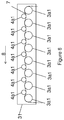
- a plurality of supports (31, 32) each supporting a series (2x1, 2x2) of cylinders are disposed one above the other.
- the space between each support allowing at least the passage of a container so that the container (1) can be deposited on two adjacent cylindrical rollers.
- the supports (31, 32) are mounted as removable shelves held by common uprights (13).
- a shaft (14) transmits the rotation of the motor to the drive pulleys (6) of each support.
- the distance (d1) between two adjacent rollers (2a1, 2b1) of a first series (2x1) of cylindrical rollers is different from the distance (d2) between two adjacent cylindrical rollers (2a2, 2b2) of a second series (2x2) of cylindrical rollers.
- the distance d1 between two rollers (2a1, 2b1) adjacent rolls of a first series (2x1) cylindrical rollers may be, for example, smaller than the distance d2 between two adjacent cylindrical rollers (2a2, 2b2) of a second series (2x2) of cylindrical rollers.
- cylindrical containers (1) of small diameters may be arranged on the first series (2x1) of cylindrical rollers while containers (1) of larger diameters may be arranged on the second (2x2) series of cylindrical rollers.
- the stirring or storage system may include a plurality of supports supporting a plurality of cylindrical roller sets. Each series of cylindrical rollers may have distances between each cylindrical roller different from one series to another.
- the one or more supports (4) have a V-shaped section (S1) with an angle of 90 °.
- the V-shaped section defines a portion of the support for receiving the cylindrical rollers.
- a branch of the V is extended by a straight line (S2) which defines a horizontal part of the support on which is fixed the pulley (6) training.
- This system makes it possible to maintain the viscosity over time by eliminating the thixotropic effects of the paint, to eliminate the emulsion during a shaking operation, to prevent the paint from hardening after the opening of a new paint container, to improve the ergonomics of the already existing stirring systems, to reduce the motive power to be used due to the low speed of rotation, to reduce the noise level of the system, to eliminate the possibility of leakage at the level of the closing the containers by the covers which is a recurring problem on conventional systems, to improve the grip of the lid by the handle and no longer a handle as in conventional systems and to be able to set up bottles of paint and not only pots.
Landscapes
- Chemical & Material Sciences (AREA)
- Chemical Kinetics & Catalysis (AREA)
- Dispersion Chemistry (AREA)
- Coating Apparatus (AREA)
Applications Claiming Priority (2)
| Application Number | Priority Date | Filing Date | Title |
|---|---|---|---|
| FR1250234A FR2985452B1 (fr) | 2012-01-10 | 2012-01-10 | Systeme d'agitation ou de conservation de peintures |
| PCT/EP2012/070962 WO2013104443A1 (fr) | 2012-01-10 | 2012-10-23 | Systeme d'agitation ou de conservation de peintures |
Publications (2)
| Publication Number | Publication Date |
|---|---|
| EP2802409A1 EP2802409A1 (fr) | 2014-11-19 |
| EP2802409B1 true EP2802409B1 (fr) | 2016-04-06 |
Family
ID=47189893
Family Applications (1)
| Application Number | Title | Priority Date | Filing Date |
|---|---|---|---|
| EP12787390.9A Not-in-force EP2802409B1 (fr) | 2012-01-10 | 2012-10-23 | Systeme d'agitation ou de conservation de peintures |
Country Status (6)
| Country | Link |
|---|---|
| US (1) | US9227163B2 (pl) |
| EP (1) | EP2802409B1 (pl) |
| ES (1) | ES2574502T3 (pl) |
| FR (1) | FR2985452B1 (pl) |
| PL (1) | PL2802409T3 (pl) |
| WO (1) | WO2013104443A1 (pl) |
Families Citing this family (4)
| Publication number | Priority date | Publication date | Assignee | Title |
|---|---|---|---|---|
| FR2985452B1 (fr) * | 2012-01-10 | 2014-02-21 | Aeml | Systeme d'agitation ou de conservation de peintures |
| US11779892B2 (en) * | 2013-10-16 | 2023-10-10 | X-Pert Paint Mixing Systems, Inc. | Paint storage and mixing system |
| US9808777B2 (en) * | 2014-02-20 | 2017-11-07 | Crayola, Llc | Paint maker and mixing device |
| US11745153B2 (en) * | 2018-06-04 | 2023-09-05 | Gideon Samid | Quantum fluid operation: technology for effective mixing, reacting, and separating fluids |
Family Cites Families (20)
| Publication number | Priority date | Publication date | Assignee | Title |
|---|---|---|---|---|
| US2006451A (en) * | 1933-01-02 | 1935-07-02 | United Shoe Machinery Corp | Receptacle holder |
| GB1317841A (en) * | 1971-01-18 | 1973-05-23 | Denley Tech Ltd | Apparatus for mixing the contents within containers |
| US3711379A (en) * | 1971-06-24 | 1973-01-16 | Cenco Medical Health Supply Co | Rotating flask culture apparatus |
| US4307965A (en) * | 1980-05-30 | 1981-12-29 | Innovative Medical Systems Corp. | Mixing apparatus |
| FR2521493B1 (fr) * | 1982-02-18 | 1986-08-22 | Fillon Pichon Sa | Armoire agitatrice et distributrice notamment pour produits colorants |
| US4526215A (en) * | 1983-07-14 | 1985-07-02 | Harrison William J | Apparatus for forming mixtures of fluids |
| EP0143145B1 (de) * | 1983-11-26 | 1987-09-23 | Heinz Wulfert Maschinenbau GmbH & Co. KG | Regal zur Aufnahme von Lackdosen |
| FR2649911B1 (fr) * | 1989-07-18 | 1992-12-31 | Fillon Pichon Sa | Armoire modulaire pour agitateur de peintures et produits analogues |
| DE19858188A1 (de) * | 1998-12-17 | 2000-07-06 | Centeon Pharma Gmbh | Verfahren zum Auflösen von Albuminflocken in einer Flüssigkeit sowie Einrichtung zur Durchführung des Verfahrens |
| US6511218B2 (en) * | 2001-04-05 | 2003-01-28 | Dedoes Industries, Inc. | Cover assembly for a paint can |
| CN100438963C (zh) * | 2001-11-30 | 2008-12-03 | 菲永技术公司 | 油漆搅拌机和它的安装方法 |
| DE10227105A1 (de) * | 2002-06-18 | 2004-01-22 | Johann Maier | Vorrichtung zum Überkopf Schütteln |
| US20070133348A1 (en) * | 2003-06-03 | 2007-06-14 | Oleg Naljotov | Remuage - riddling machine |
| EP1488847B1 (fr) * | 2003-06-19 | 2008-04-16 | Fillon Investissement | Armoire modulaire pour le stockage et l'entraînement de pots agitateurs |
| US7431183B2 (en) * | 2004-08-03 | 2008-10-07 | Dedoes Industries, Inc. | Cover assembly for a paint can having an improved seal |
| US20080251478A1 (en) * | 2005-09-02 | 2008-10-16 | Jaskowski Troy D | Wine Bottle Rotation System |
| US20090279379A1 (en) * | 2008-05-07 | 2009-11-12 | Gurney John J | Blender for containerized products |
| US8002458B2 (en) * | 2009-01-07 | 2011-08-23 | Al Saint | Riddling machine system |
| FI122584B (fi) * | 2009-11-20 | 2012-03-30 | Xemec Oy | Sekoitin maalipurkin sisällön sekoittamiseksi |
| FR2985452B1 (fr) * | 2012-01-10 | 2014-02-21 | Aeml | Systeme d'agitation ou de conservation de peintures |
-
2012
- 2012-01-10 FR FR1250234A patent/FR2985452B1/fr not_active Expired - Fee Related
- 2012-10-23 WO PCT/EP2012/070962 patent/WO2013104443A1/fr not_active Ceased
- 2012-10-23 EP EP12787390.9A patent/EP2802409B1/fr not_active Not-in-force
- 2012-10-23 US US14/370,238 patent/US9227163B2/en not_active Expired - Fee Related
- 2012-10-23 PL PL12787390.9T patent/PL2802409T3/pl unknown
- 2012-10-23 ES ES12787390.9T patent/ES2574502T3/es active Active
Also Published As
| Publication number | Publication date |
|---|---|
| US20150023129A1 (en) | 2015-01-22 |
| ES2574502T3 (es) | 2016-06-20 |
| FR2985452B1 (fr) | 2014-02-21 |
| WO2013104443A1 (fr) | 2013-07-18 |
| PL2802409T3 (pl) | 2016-10-31 |
| EP2802409A1 (fr) | 2014-11-19 |
| FR2985452A1 (fr) | 2013-07-12 |
| US9227163B2 (en) | 2016-01-05 |
Similar Documents
| Publication | Publication Date | Title |
|---|---|---|
| EP2802409B1 (fr) | Systeme d'agitation ou de conservation de peintures | |
| EP1040773B1 (fr) | Distributeur portatif pour le conditionnement et la distribution de produits cosmétiques colorés | |
| EP1541224B1 (fr) | Agitateur pour produits chimiques contenus dans des bidons | |
| FR2770154A1 (fr) | Centrifugeuse a rotor demontable et a dispositif de blocage axial du rotor sur une tete d'entrainement, et rotor pour une telle centrifugeuse | |
| EP0778080B1 (fr) | Tête d'entraínement et couvercle pour pots agitateurs | |
| DK2646138T3 (en) | STEERING SYSTEM AND PROCEDURE | |
| FR2668079A1 (fr) | Godet melangeur pour un malaxeur centrifuge planetaire, et malaxeur recevant de tels godets. | |
| US20180162156A1 (en) | Stirrer for a viscous liquid | |
| FR2618662A1 (fr) | Cuve auxiliaire de travail pour robot de cuisine | |
| CA2210512A1 (fr) | Couvercle agitateur pour boite de teinte sur les machines d'agitation de peinture | |
| EP2911774B1 (fr) | Couvercle agitateur et système utilisant le couvercle agitateur | |
| WO2000036960A1 (fr) | Robot menager multifonctions | |
| FR2715867A1 (fr) | Dispositif pour mélanger et préparer des matériaux susceptibles de s'écouler. | |
| FR2932697A1 (fr) | Dispositif d'agitation et son procede de reglage | |
| EP1815906A1 (fr) | Malaxeur à cuve fixe | |
| FR2713510A1 (fr) | Dispositif pour préparer à l'abri de l'air, une pâte à usage cosmétique. | |
| FR2785953A1 (fr) | Installation pour l'agitation du contenu, tel que de la peinture, de pots melangeurs | |
| JP6576623B2 (ja) | 混合装置 | |
| FR2882299A1 (fr) | Dispositif d'agitation pour boite de peinture a fonctions evolutives en matiere plastique | |
| EP1784252B1 (fr) | Dispositif de positionnement de pot melangeur dans une armoire a etageres et armoire equipee de tels dispositifs | |
| EP3845103B1 (fr) | Dispositif melangeur | |
| EP0803282A1 (fr) | Baratte utilisable dans le domaine de l'agroalimentaire | |
| FR3093442A1 (fr) | Méthode de mélange d'un liquide visqueux par un mélangeur à récipient rotatif exempt d'organe de brassage du liquide. | |
| EP3651889B1 (fr) | Dispositif d'agitation de fluide et couvercle equipe d'un tel dispositif d'agitation | |
| FR2899129A3 (fr) | Dispositif pour melanger ou amalgamer des vernis, des peintures, ou analogues |
Legal Events
| Date | Code | Title | Description |
|---|---|---|---|
| PUAI | Public reference made under article 153(3) epc to a published international application that has entered the european phase |
Free format text: ORIGINAL CODE: 0009012 |
|
| 17P | Request for examination filed |
Effective date: 20140807 |
|
| AK | Designated contracting states |
Kind code of ref document: A1 Designated state(s): AL AT BE BG CH CY CZ DE DK EE ES FI FR GB GR HR HU IE IS IT LI LT LU LV MC MK MT NL NO PL PT RO RS SE SI SK SM TR |
|
| DAX | Request for extension of the european patent (deleted) | ||
| REG | Reference to a national code |
Ref country code: DE Ref legal event code: R079 Ref document number: 602012016757 Country of ref document: DE Free format text: PREVIOUS MAIN CLASS: B01F0009020000 Ipc: B01F0009000000 |
|
| GRAP | Despatch of communication of intention to grant a patent |
Free format text: ORIGINAL CODE: EPIDOSNIGR1 |
|
| RIC1 | Information provided on ipc code assigned before grant |
Ipc: B44D 3/06 20060101ALI20151119BHEP Ipc: B01F 9/02 20060101ALI20151119BHEP Ipc: B01F 3/12 20060101ALI20151119BHEP Ipc: B01F 9/00 20060101AFI20151119BHEP |
|
| INTG | Intention to grant announced |
Effective date: 20151201 |
|
| GRAS | Grant fee paid |
Free format text: ORIGINAL CODE: EPIDOSNIGR3 |
|
| GRAA | (expected) grant |
Free format text: ORIGINAL CODE: 0009210 |
|
| AK | Designated contracting states |
Kind code of ref document: B1 Designated state(s): AL AT BE BG CH CY CZ DE DK EE ES FI FR GB GR HR HU IE IS IT LI LT LU LV MC MK MT NL NO PL PT RO RS SE SI SK SM TR |
|
| REG | Reference to a national code |
Ref country code: GB Ref legal event code: FG4D Free format text: NOT ENGLISH |
|
| REG | Reference to a national code |
Ref country code: AT Ref legal event code: REF Ref document number: 787118 Country of ref document: AT Kind code of ref document: T Effective date: 20160415 Ref country code: CH Ref legal event code: EP |
|
| REG | Reference to a national code |
Ref country code: IE Ref legal event code: FG4D Free format text: LANGUAGE OF EP DOCUMENT: FRENCH |
|
| REG | Reference to a national code |
Ref country code: DE Ref legal event code: R096 Ref document number: 602012016757 Country of ref document: DE |
|
| REG | Reference to a national code |
Ref country code: ES Ref legal event code: FG2A Ref document number: 2574502 Country of ref document: ES Kind code of ref document: T3 Effective date: 20160620 |
|
| REG | Reference to a national code |
Ref country code: NL Ref legal event code: FP |
|
| REG | Reference to a national code |
Ref country code: LT Ref legal event code: MG4D |
|
| REG | Reference to a national code |
Ref country code: AT Ref legal event code: MK05 Ref document number: 787118 Country of ref document: AT Kind code of ref document: T Effective date: 20160406 |
|
| REG | Reference to a national code |
Ref country code: FR Ref legal event code: PLFP Year of fee payment: 5 |
|
| PG25 | Lapsed in a contracting state [announced via postgrant information from national office to epo] |
Ref country code: FI Free format text: LAPSE BECAUSE OF FAILURE TO SUBMIT A TRANSLATION OF THE DESCRIPTION OR TO PAY THE FEE WITHIN THE PRESCRIBED TIME-LIMIT Effective date: 20160406 Ref country code: IS Free format text: LAPSE BECAUSE OF FAILURE TO SUBMIT A TRANSLATION OF THE DESCRIPTION OR TO PAY THE FEE WITHIN THE PRESCRIBED TIME-LIMIT Effective date: 20160806 Ref country code: NO Free format text: LAPSE BECAUSE OF FAILURE TO SUBMIT A TRANSLATION OF THE DESCRIPTION OR TO PAY THE FEE WITHIN THE PRESCRIBED TIME-LIMIT Effective date: 20160706 Ref country code: LT Free format text: LAPSE BECAUSE OF FAILURE TO SUBMIT A TRANSLATION OF THE DESCRIPTION OR TO PAY THE FEE WITHIN THE PRESCRIBED TIME-LIMIT Effective date: 20160406 |
|
| PG25 | Lapsed in a contracting state [announced via postgrant information from national office to epo] |
Ref country code: SE Free format text: LAPSE BECAUSE OF FAILURE TO SUBMIT A TRANSLATION OF THE DESCRIPTION OR TO PAY THE FEE WITHIN THE PRESCRIBED TIME-LIMIT Effective date: 20160406 Ref country code: GR Free format text: LAPSE BECAUSE OF FAILURE TO SUBMIT A TRANSLATION OF THE DESCRIPTION OR TO PAY THE FEE WITHIN THE PRESCRIBED TIME-LIMIT Effective date: 20160707 Ref country code: RS Free format text: LAPSE BECAUSE OF FAILURE TO SUBMIT A TRANSLATION OF THE DESCRIPTION OR TO PAY THE FEE WITHIN THE PRESCRIBED TIME-LIMIT Effective date: 20160406 Ref country code: LV Free format text: LAPSE BECAUSE OF FAILURE TO SUBMIT A TRANSLATION OF THE DESCRIPTION OR TO PAY THE FEE WITHIN THE PRESCRIBED TIME-LIMIT Effective date: 20160406 Ref country code: HR Free format text: LAPSE BECAUSE OF FAILURE TO SUBMIT A TRANSLATION OF THE DESCRIPTION OR TO PAY THE FEE WITHIN THE PRESCRIBED TIME-LIMIT Effective date: 20160406 Ref country code: PT Free format text: LAPSE BECAUSE OF FAILURE TO SUBMIT A TRANSLATION OF THE DESCRIPTION OR TO PAY THE FEE WITHIN THE PRESCRIBED TIME-LIMIT Effective date: 20160808 Ref country code: AT Free format text: LAPSE BECAUSE OF FAILURE TO SUBMIT A TRANSLATION OF THE DESCRIPTION OR TO PAY THE FEE WITHIN THE PRESCRIBED TIME-LIMIT Effective date: 20160406 |
|
| REG | Reference to a national code |
Ref country code: DE Ref legal event code: R097 Ref document number: 602012016757 Country of ref document: DE |
|
| PG25 | Lapsed in a contracting state [announced via postgrant information from national office to epo] |
Ref country code: RO Free format text: LAPSE BECAUSE OF FAILURE TO SUBMIT A TRANSLATION OF THE DESCRIPTION OR TO PAY THE FEE WITHIN THE PRESCRIBED TIME-LIMIT Effective date: 20160406 Ref country code: CZ Free format text: LAPSE BECAUSE OF FAILURE TO SUBMIT A TRANSLATION OF THE DESCRIPTION OR TO PAY THE FEE WITHIN THE PRESCRIBED TIME-LIMIT Effective date: 20160406 Ref country code: EE Free format text: LAPSE BECAUSE OF FAILURE TO SUBMIT A TRANSLATION OF THE DESCRIPTION OR TO PAY THE FEE WITHIN THE PRESCRIBED TIME-LIMIT Effective date: 20160406 Ref country code: SK Free format text: LAPSE BECAUSE OF FAILURE TO SUBMIT A TRANSLATION OF THE DESCRIPTION OR TO PAY THE FEE WITHIN THE PRESCRIBED TIME-LIMIT Effective date: 20160406 Ref country code: DK Free format text: LAPSE BECAUSE OF FAILURE TO SUBMIT A TRANSLATION OF THE DESCRIPTION OR TO PAY THE FEE WITHIN THE PRESCRIBED TIME-LIMIT Effective date: 20160406 |
|
| PLBE | No opposition filed within time limit |
Free format text: ORIGINAL CODE: 0009261 |
|
| STAA | Information on the status of an ep patent application or granted ep patent |
Free format text: STATUS: NO OPPOSITION FILED WITHIN TIME LIMIT |
|
| PG25 | Lapsed in a contracting state [announced via postgrant information from national office to epo] |
Ref country code: SM Free format text: LAPSE BECAUSE OF FAILURE TO SUBMIT A TRANSLATION OF THE DESCRIPTION OR TO PAY THE FEE WITHIN THE PRESCRIBED TIME-LIMIT Effective date: 20160406 |
|
| 26N | No opposition filed |
Effective date: 20170110 |
|
| PG25 | Lapsed in a contracting state [announced via postgrant information from national office to epo] |
Ref country code: SI Free format text: LAPSE BECAUSE OF FAILURE TO SUBMIT A TRANSLATION OF THE DESCRIPTION OR TO PAY THE FEE WITHIN THE PRESCRIBED TIME-LIMIT Effective date: 20160406 |
|
| REG | Reference to a national code |
Ref country code: CH Ref legal event code: PL |
|
| REG | Reference to a national code |
Ref country code: IE Ref legal event code: MM4A |
|
| PG25 | Lapsed in a contracting state [announced via postgrant information from national office to epo] |
Ref country code: LI Free format text: LAPSE BECAUSE OF NON-PAYMENT OF DUE FEES Effective date: 20161031 Ref country code: CH Free format text: LAPSE BECAUSE OF NON-PAYMENT OF DUE FEES Effective date: 20161031 |
|
| PG25 | Lapsed in a contracting state [announced via postgrant information from national office to epo] |
Ref country code: LU Free format text: LAPSE BECAUSE OF NON-PAYMENT OF DUE FEES Effective date: 20161023 |
|
| REG | Reference to a national code |
Ref country code: FR Ref legal event code: PLFP Year of fee payment: 6 |
|
| PG25 | Lapsed in a contracting state [announced via postgrant information from national office to epo] |
Ref country code: IE Free format text: LAPSE BECAUSE OF NON-PAYMENT OF DUE FEES Effective date: 20161023 |
|
| PGFP | Annual fee paid to national office [announced via postgrant information from national office to epo] |
Ref country code: FR Payment date: 20171026 Year of fee payment: 6 Ref country code: DE Payment date: 20171121 Year of fee payment: 6 Ref country code: NL Payment date: 20171030 Year of fee payment: 6 |
|
| PGFP | Annual fee paid to national office [announced via postgrant information from national office to epo] |
Ref country code: GB Payment date: 20171123 Year of fee payment: 6 Ref country code: ES Payment date: 20171121 Year of fee payment: 6 Ref country code: BE Payment date: 20171030 Year of fee payment: 6 Ref country code: PL Payment date: 20171005 Year of fee payment: 6 Ref country code: IT Payment date: 20171024 Year of fee payment: 6 |
|
| PG25 | Lapsed in a contracting state [announced via postgrant information from national office to epo] |
Ref country code: HU Free format text: LAPSE BECAUSE OF FAILURE TO SUBMIT A TRANSLATION OF THE DESCRIPTION OR TO PAY THE FEE WITHIN THE PRESCRIBED TIME-LIMIT; INVALID AB INITIO Effective date: 20121023 |
|
| PG25 | Lapsed in a contracting state [announced via postgrant information from national office to epo] |
Ref country code: MT Free format text: LAPSE BECAUSE OF FAILURE TO SUBMIT A TRANSLATION OF THE DESCRIPTION OR TO PAY THE FEE WITHIN THE PRESCRIBED TIME-LIMIT Effective date: 20160406 Ref country code: CY Free format text: LAPSE BECAUSE OF FAILURE TO SUBMIT A TRANSLATION OF THE DESCRIPTION OR TO PAY THE FEE WITHIN THE PRESCRIBED TIME-LIMIT Effective date: 20160406 Ref country code: MK Free format text: LAPSE BECAUSE OF FAILURE TO SUBMIT A TRANSLATION OF THE DESCRIPTION OR TO PAY THE FEE WITHIN THE PRESCRIBED TIME-LIMIT Effective date: 20160406 Ref country code: MC Free format text: LAPSE BECAUSE OF FAILURE TO SUBMIT A TRANSLATION OF THE DESCRIPTION OR TO PAY THE FEE WITHIN THE PRESCRIBED TIME-LIMIT Effective date: 20160406 |
|
| PG25 | Lapsed in a contracting state [announced via postgrant information from national office to epo] |
Ref country code: BG Free format text: LAPSE BECAUSE OF FAILURE TO SUBMIT A TRANSLATION OF THE DESCRIPTION OR TO PAY THE FEE WITHIN THE PRESCRIBED TIME-LIMIT Effective date: 20160406 |
|
| PG25 | Lapsed in a contracting state [announced via postgrant information from national office to epo] |
Ref country code: TR Free format text: LAPSE BECAUSE OF FAILURE TO SUBMIT A TRANSLATION OF THE DESCRIPTION OR TO PAY THE FEE WITHIN THE PRESCRIBED TIME-LIMIT Effective date: 20160406 Ref country code: AL Free format text: LAPSE BECAUSE OF FAILURE TO SUBMIT A TRANSLATION OF THE DESCRIPTION OR TO PAY THE FEE WITHIN THE PRESCRIBED TIME-LIMIT Effective date: 20160406 |
|
| REG | Reference to a national code |
Ref country code: DE Ref legal event code: R119 Ref document number: 602012016757 Country of ref document: DE |
|
| REG | Reference to a national code |
Ref country code: NL Ref legal event code: MM Effective date: 20181101 |
|
| GBPC | Gb: european patent ceased through non-payment of renewal fee |
Effective date: 20181023 |
|
| REG | Reference to a national code |
Ref country code: BE Ref legal event code: MM Effective date: 20181031 |
|
| PG25 | Lapsed in a contracting state [announced via postgrant information from national office to epo] |
Ref country code: DE Free format text: LAPSE BECAUSE OF NON-PAYMENT OF DUE FEES Effective date: 20190501 Ref country code: NL Free format text: LAPSE BECAUSE OF NON-PAYMENT OF DUE FEES Effective date: 20181101 |
|
| PG25 | Lapsed in a contracting state [announced via postgrant information from national office to epo] |
Ref country code: FR Free format text: LAPSE BECAUSE OF NON-PAYMENT OF DUE FEES Effective date: 20181031 Ref country code: BE Free format text: LAPSE BECAUSE OF NON-PAYMENT OF DUE FEES Effective date: 20181031 |
|
| PG25 | Lapsed in a contracting state [announced via postgrant information from national office to epo] |
Ref country code: GB Free format text: LAPSE BECAUSE OF NON-PAYMENT OF DUE FEES Effective date: 20181023 Ref country code: IT Free format text: LAPSE BECAUSE OF NON-PAYMENT OF DUE FEES Effective date: 20181023 |
|
| REG | Reference to a national code |
Ref country code: ES Ref legal event code: FD2A Effective date: 20191202 |
|
| PG25 | Lapsed in a contracting state [announced via postgrant information from national office to epo] |
Ref country code: ES Free format text: LAPSE BECAUSE OF NON-PAYMENT OF DUE FEES Effective date: 20181024 |
|
| PG25 | Lapsed in a contracting state [announced via postgrant information from national office to epo] |
Ref country code: PL Free format text: LAPSE BECAUSE OF NON-PAYMENT OF DUE FEES Effective date: 20181023 |