EP2801880A2 - Geräteüberwachungssystem - Google Patents
Geräteüberwachungssystem Download PDFInfo
- Publication number
- EP2801880A2 EP2801880A2 EP14161298.6A EP14161298A EP2801880A2 EP 2801880 A2 EP2801880 A2 EP 2801880A2 EP 14161298 A EP14161298 A EP 14161298A EP 2801880 A2 EP2801880 A2 EP 2801880A2
- Authority
- EP
- European Patent Office
- Prior art keywords
- sensor
- equipment
- sensors
- characteristic
- sensor characteristic
- Prior art date
- Legal status (The legal status is an assumption and is not a legal conclusion. Google has not performed a legal analysis and makes no representation as to the accuracy of the status listed.)
- Withdrawn
Links
Images


Classifications
-
- G—PHYSICS
- G01—MEASURING; TESTING
- G01M—TESTING STATIC OR DYNAMIC BALANCE OF MACHINES OR STRUCTURES; TESTING OF STRUCTURES OR APPARATUS, NOT OTHERWISE PROVIDED FOR
- G01M15/00—Testing of engines
- G01M15/14—Testing gas-turbine engines or jet-propulsion engines
-
- G—PHYSICS
- G01—MEASURING; TESTING
- G01D—MEASURING NOT SPECIALLY ADAPTED FOR A SPECIFIC VARIABLE; ARRANGEMENTS FOR MEASURING TWO OR MORE VARIABLES NOT COVERED IN A SINGLE OTHER SUBCLASS; TARIFF METERING APPARATUS; MEASURING OR TESTING NOT OTHERWISE PROVIDED FOR
- G01D3/00—Indicating or recording apparatus with provision for the special purposes referred to in the subgroups
- G01D3/08—Indicating or recording apparatus with provision for the special purposes referred to in the subgroups with provision for safeguarding the apparatus, e.g. against abnormal operation, against breakdown
Definitions
- the present invention relates to asset condition or health monitoring and more particularly to the monitoring of machines in service.
- Asset health monitoring commonly referred to as equipment health monitoring (EHM) is based around the premise of sensing a plurality of operational variables for an asset during use.
- the gathered data can be used to determine an operational state of the asset. Additionally the data can be processed to identify the current condition or health status of the equipment.
- the output of the EHM system provides information to an operator which can be used to manage the operation of the equipment, for example by controlling the equipment in a manner which is sympathetic to the condition of the equipment or else by scheduling suitable repair or maintenance work.
- the level of sophistication of an EHM system is often determined by the value or complexity of the asset. More particularly, sophisticated EHM systems are most often implemented where the cost of maintenance work to be carried out on the assets is relatively high. This therefore demands that maintenance schedules are optimised so that maintenance can be carried out effectively at appropriate intervals and with minimal disruption to the asset operation.
- Gas turbine engines are one example of an asset for which EHM systems are becoming crucial to efficient asset management.
- EHM systems for gas turbine engines look for anomalies in the long term trends of measured engine parameters. It is known to undertake trending of process variables (measured parameters) in order to improve condition monitoring without necessitating additional sensors or processing. Examples of such trending are described in WO/2007/133,543 . Methods for identifying features in received sensor data and determining a machine operation diagnosis from such features are disclosed in WO/2011/003688 .
- Such investigations can be manually time consuming, due to the need to access service and maintenance records for the asset and/or contact a service engineer to determine any relevant system changes that may have occurred at the time of the anomaly, and cause uncertainty over the operational state of the asset in the interim.
- an asset monitoring system comprising a monitoring unit and a plurality of sensors onboard the asset, the sensors arranged to measure a plurality of operational variables for the asset in use and the monitoring unit arranged to receive operational variable measurements output from the sensors, wherein the monitoring unit is arranged to determine a current value of a sensor characteristic for each sensor and to compare the current sensor characteristic value with a predetermined sensor characteristic value in order to determine automatically whether a change of one or more sensors has occurred between instances of operation.
- a sensor characteristic differs from the output of the sensor during its normal sensing function (i.e. the change in the one or more properties of the sensor that occurs across its normal operating range).
- the sensor characteristic may be a passive characteristic as opposed to an active characteristic used for taking operational variable measurements for the asset.
- the sensor characteristic of the sensor may be substantially constant over the sensor's normal operating range or else may change over a magnitude of scale that is significantly less than the changes in the sensor properties used to measure the operational variable of the asset.
- the sensor characteristic may be an operational characteristic of the sensor.
- the monitoring unit may determine automatically whether a change of one or more sensors has occurred between instances of operation of the asset.
- the sensor characteristic may be an integral or intrinsic characteristic of the sensor. Additionally or alternatively, the sensor characteristic may comprise a characteristic of a component added to the sensor, e.g. a dedicated component, for example outside of its normal sensing function.
- the sensor characteristic is common to a plurality of sensors.
- the monitoring unit may thus be able to determine a common sensor characteristic for a number of different types of sensor used in the system.
- the sensor characteristic may comprise an electrical or electronic property of the sensor.
- the sensor characteristic may comprise a measure of conductivity for the sensor such as a resistance or impedance of the sensor. Additionally or alternatively, the sensor characteristic may comprise a counter-electromotive force (or back EMF) or bias current or similar measurable electrical property.
- the monitoring unit may determine the sensor characteristic over a range of variance for said sensor characteristic. Such variance may occur for example to natural variance in material properties, manufacturing tolerances or other properties for the sensor.
- the monitoring unit may determine the sensor characteristic with a resolution of at least 1 in 100 (i.e. at least one hundredth of the range of variance for the sensor).
- the predetermined sensor characteristic value is a threshold value or band for the sensor characteristic of the sensor.
- the monitoring unit may provide a digital output corresponding to whether or not the current determined sensor characteristic value exceeds said threshold value or band (i.e. +/- threshold around the predetermined value). That digital output may indicate whether or not a sensor has been changed.
- the predetermined sensor characteristic value is one or more previously stored values for the sensor characteristic.
- the previously stored value may be the receding value, e.g. stored for a previous instance of use of the asset.
- the previously stored value may be determined from a plurality of previously stored values, such as an average or trend of previously stored values.
- Each sensor may have an identifier.
- the identifier may comprise an alphanumeric string or code or other form of identification data.
- the identifier is preferably common to all sensors or components of the same type.
- the identifier may be, or comprise, a part number. Thus the sensor characteristic is distinct from the identifier or any other data used to identify the sensor.
- the monitoring unit may also determine one or more identifier for each sensor.
- the identifier may be read from the sensor.
- the monitoring unit may determine the current value of the sensor characteristic for each sensor for each instance of use of the asset. The determination may be made at the start of each instance of use, for example as part of a start-up procedure. An instance of use may be determined in dependence upon a supply (or cessation or reduction) of power to the asset or one or more portions thereof, for example including to the monitoring unit and/or sensors. An instance of use may be determined from one or more sensor readings.
- the monitoring unit may determine the current value of the sensor characteristic one or more time after the start of each instance of use, for example, incrementally during an instance of use and/or at an end of an instance of use.
- the monitoring unit may use the determined value of the sensor characteristic to qualify a value of the operational variable measurement output from the sensor or vice versa.
- the current sensor characteristic may be used to identify the type of sensor.
- each sensor of a particular type may have associated therewith a band or range of sensor characteristic values (e.g. the predetermined characteristic values). If the current sensor characteristic value falls within the range, of one sensor type, it may be identified as being that type of sensor.
- Each sensor type or range of sensor characteristic values may have a probability distribution associated therewith (e.g. a normal distribution).
- the asset is typically a high value asset and may comprise a machine.
- the asset may comprise a complex machine, for example having multiple sub-assemblies and/or hundreds or thousands of components.
- the asset may comprise a machine for use aeronautical, power generation or any other industrial application.
- the asset may comprise an engine, such as, for example, a gas turbine engine.
- the monitoring system may comprise tens or more than a hundred sensors.
- an asset monitoring method comprising, for each instance of operation: receiving at an asset monitoring unit operational variable measurements output from a plurality of sensors onboard the asset in use; obtaining a current value of an sensor characteristic for each sensor; and comparing the current sensor characteristic value with a predetermined sensor characteristic value in order to determine automatically within the asset monitoring unit whether a change of one or more sensors has occurred between instances of operation of the asset.
- a data carrier comprising machine readable instructions for control of an asset monitoring unit to receive operational variable measurements output from a plurality of sensors during use of the asset; obtain a current value of an sensor characteristic for each sensor; and comparing the current sensor characteristic value with a predetermined sensor characteristic value in order to determine whether a change of one or more sensors has occurred between instances of operation of the asset.
- a change of one or more sensors may comprise a sensor swap, replacement or repair.
- the change will comprise replacement of a sensor for another sensor of the same type, although the invention may also be used to detect the replacement of one sensor for another sensor of a different type if appropriate.
- the invention derives from the realisation of an equipment health or condition monitoring system can automatically detect a sensor or component swap and can interpret any resulting change in readings in a manner that is less likely to trigger erroneous adverse condition alarms.
- An asset as referred to herein typically refers to a machine or a number of machines, which are inter-reliant for correct operation thereof.
- Computer controlled condition monitoring systems are used conventionally to monitor the behavior of machinery. Simple algorithms may be used to monitor devices having a single, or relatively few, degrees of freedom such as valves, pistons, simple rotating drives and the like. However more complicated monitoring systems are put in place where a machine or system has a number of interdependent sub-assemblies or components, each of which having a number of control inputs and outputs. Accordingly, equipment condition monitoring units for such complex machines typically receive operation data from a number of different sub-assemblies or components of the asset. Tens or hundreds of sensors may be involved.
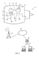
- an asset in the form of a gas turbine engine 2.
- an aircraft engine provides just one example of complex machinery to which the present invention may be applied.
- the invention may be applied to a variety of other high value assets for which the close monitoring of asset operation is important to ensure the desired life cycle of the asset is achieved, for example by allowing servicing and maintenance schedules to be planned and executed in a timely and efficient manner so as to avoid unwanted down time of the asset.
- assets may include: propulsion equipment, such as other types of engines, for example, for marine or other aerospace applications; pumps or turbines or other machinery for industrial applications, for example within the oil and gas industry, power generation, including renewable energy or nuclear energy applications.
- Examples of such assets may include steam turbines, tidal or wind turbines or the like.
- the engine 2 of Figure 1 comprises multiple sensors 4 connected via a local network 6 to an engine monitoring unit (EMU) 8.
- the asset comprises both an electronic engine controller (EEC) 10 and an EMU 8 which are in communication, at least for dissemination of data from the EEC to the EMU, but typically also for two-way communication of data.
- EEC electronic engine controller
- the EEC 9 and EMU 8 may be in communication via a data bus 12, which is typically a conventional engine or aircraft data bus.
- the EEC may receive data from the sensors 4 via local network which may be communicated to the EMU 8.
- the EMU 8 may receive sensor data without involving the EEC.
- a wired connection may be established between the sensors 4 and the EMU 8 for transmission of sensor data thereto.
- the local network 6 for the asset 2 may comprise a so-called harness, thereby providing such wired connections.
- a suitable connection may be achieved using wireless communication technology, such as Wi-Fi (RTM), Bluetooth (RTM), or similar.
- Data relating to the operation of an engine 2 is collected over the engine operational life using sensors 4 and comprises a measure of a variety of operational parameters under conventional equipment health monitoring (EHM) practices.
- EHM equipment health monitoring
- Conventional types of sensors known to those skilled in the art are located on an engine or aircraft to generate readings of any or any combination of operating time, cycle time or frequency, operational speeds (such as rotor speeds), temperatures, pressures (such as fluid pressure), fluid flow (including fuel consumption), vibrations, accelerations, forces and the like, as well as operational context, such as for example Weight on Wheels (WoW) signals, engine operator inputs via manual controls, other engine demands, or the like.
- WoW Weight on Wheels
- Figure 1 also shows an overview of a wider system 10 in which the present invention may be incorporated. Whilst a single engine is referred to below, it will be appreciated that the invention can be applied to other gas turbine engine scenarios, including multiple engines on a single aircraft, a fleet of aircraft, or else one or more gas turbine engine used for other applications.
- the EMU 8 gathers the necessary data from the data bus 12 and records (and/or conditions) the data needed for EHM purposes for secure transmission to a remote monitoring centre, where the data is received and processed and the necessary resulting actions determined. In this manner the data may be stored both locally and/or remotely.
- the operational data for the engines 2 is communicated to a remote or central control and/or monitoring facility, where records for all engines in the fleet are gathered. This is achieved by transmission of operational data, typically at the end of each aircraft flight, from the engine or associated aircraft to a control centre server 14.
- one or more wireless transmitters 16 associated with each engine transmit data signals to a receiver 18, which may comprise a base station, for example within a cellular network.
- the data is transmitted from the receiver 18 to the server 14 via a wide area network (WAN) such as the internet 20.
- WAN wide area network
- data may be transmitted via existing aviation communication channels, e.g. in flight via satellite to ground.
- operational data may be recorded to a removable data storage device such as a memory stick or laptop for subsequent retrieval by and/or transmission to the server 14.
- other wireless data transmission protocols may be used such as Wi-Fi.
- the server 14 is associated with a network 22, typically via a secure local area or wide area network, over which the operational data can be disseminated for processing and or analysis using networked work stations 24.
- the combination of server 14 and network 22 provides a remote monitoring or control centre and may comprise an asset monitoring service provider or else the asset operator organisation.
- the relevant processing of data could be carried out on-board an engine 2 or aircraft by EMU 8 or else by other processing means mounted thereon. Necessary actions could then be taken by the local/on-board monitoring device and/or subsequently communicated to the relevant monitoring or control centre and/or engine operator as necessary.
- the EMU could perform a first stage of data processing to determine the operational condition of the asset. If a normal asset operation is determined, then only summary data or a subset of the data need be transmitted to the monitoring facility. However if an unfavorable condition or else a fault is determined by the monitoring unit, then a larger volume of data pertaining to said condition or fault will be transmitted.
- the system would also allow for a mass offload of operation data from the monitoring unit in certain circumstances.
- the operational data i.e. the values of the operational variables
- the operational data from the sensors 4 is processed locally or remotely so as to allow appropriate actions to be undertaken, such as the output and/or transmission of information, instructions, alerts and/or control signals derived from the operational variables.
- FIG 2 there is shown a schematic representation of an on-board system according to the invention.
- the EMU 8 can receive the measurements from sensors 4 in a normal manner in which the sensors operate passively with respect to the EMU.
- the EMU 8 is also configured to measure a characteristic of the sensors 4 themselves. This may be performed by one or more modules of computer-readable code, e.g. software implemented routines for control of the EMU 8, to obtain measurements of one or more characteristic of the sensors at one or more times during an instance of use of the engine 2.
- EMU 8 may enter a test or checking routine or mode, in which the EMU gathers the required readings from the sensors. This may be instigated during engine startup, e.g. as a test phase, prior to entering normal operation or else at one or more times during normal operation of the EMU (i.e. concurrently). It is also possible that same routine may be entered at the end of an instance of use of the engine, e.g. after landing of an aircraft.
- the sensor characteristic measured by the EMU is preferably unique to an individual sensor such that, if one sensor is swapped for another sensor of the same type, the EMU can recognise that swap via the measured characteristic. It is important to note that the sensors of the same type are typically manufactured so as to be functionally equivalent for the primary intended purpose of the sensor. However the invention seeks to differentiate between sensors by characteristics that differ from sensor to sensor. Such characteristic may be intrinsic to the sensor based upon variations in the sensors occurring due to their method of manufacture. Alternatively such a characteristic may be artificially added to the sensor as an additional component or element to distinguish between a sensor that is already in service and one that has not yet been used.
- the EMU will need to be able to measure the operational characteristic (e.g. impedance) with enough accuracy and resolution to be able to detect the variance which naturally exists in these characteristics (e.g. impedances) from sensor to sensor.
- the operational characteristic e.g. impedance
- the operational characteristic for a particular type of sensor can vary over a normal probability distribution, such that the determined values of said characteristic that are relatively close (e.g. within 1 or 2 standard deviations) to the mean value for that type of sensor can be determined to be indicative of sensor type.
- the EMU 8 is configured to measure the impedance of sensors 4.
- the selected measured parameter will depend on a number of things including the properties of the component being monitored and so it is possible that a non-electrical characteristic of the sensor or component could be monitored instead.
- the monitoring unit in any embodiment typically has a local data store 25 to allow recording of measured sensor characteristic values.
- a first type of sensor 4A 1 does not display a significant enough variance in intrinsic impedance of the sensing element 4A to allow the monitoring unit 8 to measure reliably a change in impedance between different sensors of that type. Accordingly an impedance component 26 (i.e. having an impedance value Z A1 ) is added to the sensor such that the monitoring unit can interrogate the component 26 to establish if the sensor 4A 1 has been previously in service.
- an impedance component 26 i.e. having an impedance value Z A1
- the component 26 is modified by one or more instances of use.
- the component may deteriorate upon first use or may deteriorate over successive uses so that the monitoring unit 8 can determine whether one or more previous instances of use have been undertaken by comparing the measured value with a predetermined value, such as a threshold value or else a previously measured value.
- a separate link 28 is established between the EMU 8 and the impedance 26, in addition to a conventional wired or wireless data link 30 for sending sensor readings to the EMU 8, to undertake the necessary sensor characteristic measurement.
- the sensor 4B has an intrinsic impedance (Z B1 ), which varies sufficiently between different sensors of that type to be directly measurable by the monitoring unit 8.
- Suitable sensors of this type may include, for example, a speed probe coil or vibration sensor. The impedance of such a sensor can be measured directly using the existing link 30 without the need for additional wiring.
- the monitoring unit 8 measures the characteristic of the new sensor 4A 2 or 4B 2 and compares it to the value stored in data store 25 from the previous instance of use for sensor 4A 1 or 4B 1 . Accordingly EMU 8 can acknowledge the sensor swap from the difference in impedance values.
- a predetermined impedance value range may be stored for a particular type of sensor. Accordingly an impedance difference of greater than 5%, or even 1 % or 2%, of that range may be determined to constitute a sensor swap event. Depending on the range of the values for a sensor type, it is possible that an impedance difference, or other sensor characteristic value, of 0.1% or more may be detected and/or used to infer a sensor change.
- FIG. 3 there is shown a more detailed example of an arrangement for detecting sensor swap in a sensor having an intrinsic sensor characteristic that is measurable by EMU 8.
- the sensor 4A is a piezoelectric vibration transducer, e.g. having a seismic mass connected to a base member by a sensing element, although the other details of Figure 3 are not specific to that sensor type.
- Electronic sensor swap detection hardware and software has been added to complement a conventional EMU 8. The software resides in the microcontroller and is used to control the switching between sensor swap detection functionality when the system is first powered up and primary vibration monitoring functionality once the unit has finished initialising following a power up.
- the sensor swap detection hardware comprises a controller 32, a switching arrangement 36 and a variable frequency AC power source 34, which can supply power via suitable resistor 35.
- the power source 34 is connected to the sensor by switches 36 and resistor 35 to allow selective switching between the primary EMU function and the sensor swap detection function. Such an arrangement allows for selective application of an AC signal to the sensor 4A via existing wiring 30 of the sensor harness.
- the microcontroller 32 can apply a fixed frequency ac supply to the sensor 4A and infer the sensors impedance by measuring the magnitude of the ac voltage seen at the EMU connections to the sensor.
- the microcontroller can apply a varying AC signal to search for a frequency where the natural resonance of the sensor produces the lowest impedance to be measured. The advantage of doing this is that there may be more sensor-to-sensor variance when the resonant point is searched for as there are two parameters involved in the determination, i.e. both the frequency and the impedance measurement.
- an on/off and/or frequency control unit 37 may be implemented for control of the AC power source 34 and switches 36.
- the microcontroller can measure the magnitude of the signal after conditioning through an amplifier 38 and an analogue to digital converter 40. In this case the application measures intrinsic impedance and no extra engine harness wiring is needed.
- the sensor 4A has been provided with a dedicated added impedance 42, e.g. a resistor 42 of known value and with appropriate variance.
- a dedicated added impedance 42 e.g. a resistor 42 of known value and with appropriate variance.
- an impedance DC resistance
- Such an embodiment may be used for example if an intrinsic impedance can be identified but it does not have sufficient sensor-to-sensor variance.
- the sensor swap detection hardware is the same as described above in relation to Figure 3 with the exception of the power source arrangement 34 being modified to provide a DC power source 43.
- the electronics for such an embodiment are less complex as it is only necessary to measure DC resistance and so only on/off switch control is needed in place of an AC control.
- Thermocouples are used to measure temperature and so it is likely that the temperature of the sensor may not be the same every time the impedance measurement occurs (even when typically at EMU power up). For this reason the added resistor 42 may be selected to have a low temperature co-efficient. Any output voltage from the thermocouple would also need to be compensated for but this could be done with some feedback 44 (e.g. of temperature measurement) from the primary EMU or sensor function to the microcontroller 32. In this case the impedance could be added in series with the signal because the electronics for the primary function will itself have a high input impedance and draw relatively very little current from the sensor. Thus the effect (on the primary function of the EMU/sensor) of the addition of the resistance 42 will be insignificant.
- the provision of feedback 44 from the sensor/EMU to the sensor swap detection controller proposed for this embodiment may be used in any other embodiment as necessary. If this feature is not used, care will be needed to select an impedance which does not vary substantially with environmental parameters in order to avoid falsely detecting a sensor change, for example, due to a change of impedance when the temperature changes.
- FIG 5 an embodiment is presented that is similar to the above described example of Figure 4 .
- a sensor 4B is used having an added impedance 46 that varies significantly with an instance of use.
- a fuse 46 is added to the sensor.
- the sensor 4B has not been used on engine before the fuse 46 will be intact and present a very low impedance.
- a further switch 50 is provided under the control of the microcontroller 32. With a new sensor and an intact fuse the system would present a logic "high" to the microcontroller 32. The microcontroller can then close switch 50 and draw enough current to blow the fuse.
- the signal then presented to the microcontroller would then be a logic "low” and would remain so for the operational life of the sensor (as the fuse is now blown) until a new sensor is added.
- the microcontroller would initially see a logic "high” indication of a new sensor being used.
- This method may have the disadvantage that an extra wire 46 may be needed to be added to the existing engine harness.
- the sensor swap detection hardware/system may be provided as an integral part of the EMU or as a separate dedicated function under the control of the EMU and in communication therewith.
- the controller 32 is arranged to further receive the data indicative of the operational variables measured by said sensors.
- the controller 32 or another EMU controller can compare the currently determined sensor characteristic with a predetermined or previously stored value. A determination of a difference between the stored and current values, subject to tolerances, may be used to that a sensor swap has occurred.
- the controller 32 is arranged to further receive a data identifier for the sensor 4, such that the controller 32 can acknowledge the type of sensor that is installed.
- a part number may be used for this purpose.
- the predetermined characteristic value for the sensor may be logged against the sensor type, for example within a database stored by the EMU, such that sensor types and values can be easily updated over time as may be necessary.
- the controller 32 may determine the type of sensor installed by the determined value of the sensor characteristic. A certainty of determination may be applied based on where the sensor characteristic value lies within a probability distribution (for example, its proximity to a mean sensor characteristic value for a particular type of sensor). Additionally or alternatively, the controller 32 may determine the type of sensor installed by qualifying/comparing the received sensor characteristic value with values of the sensed operational variable measured by the sensor in use.
- the EMU or other monitoring equipment may apply a different set of instructions or routines to the analysis of the sensor data. For example a calibration routine may be entered to adjust EHM determinations for the new sensor. Additionally or alternatively an assurance rating may be applied to sensor reading for a predetermined time period after a sensor swap until a suitable trend for the new sensor has been established.
- FIG. 6 there is provided examples of calculations concerning the probability of not being able to detect the difference between two sensors.
- the probability of not being able to resolve the difference between two sensors depends on the population distribution of the sensed impedance. If an example of 5% variation in resistance/impedance for the sensor is assumed, then the range of possible voltages at the analogue to digital converter can be determined and after amplification it can be shown that a resolution of 100 different sensor types across the range can be accurately identified.
- the next sensor has a resistor also in that range.
- the probability of taking one sample and it being within +/-0.03 sigma of the mean is 0.024 (i.e. 2.4 % of the population).
- Simple examples of improving this probability even further may include either (1) reducing the ADC reference voltage to 3V to thereby resolve 170 resistor values or (2) additionally using a bi-polar ADC in conjunction with (1) to thereby resolve in excess of 1000 individual resistor values.
- (1) reducing the ADC reference voltage to 3V to thereby resolve 170 resistor values or (2) additionally using a bi-polar ADC in conjunction with (1) to thereby resolve in excess of 1000 individual resistor values.
Landscapes
- Physics & Mathematics (AREA)
- General Physics & Mathematics (AREA)
- Chemical & Material Sciences (AREA)
- Engineering & Computer Science (AREA)
- Combustion & Propulsion (AREA)
- Testing Or Calibration Of Command Recording Devices (AREA)
- Testing And Monitoring For Control Systems (AREA)
- Burglar Alarm Systems (AREA)
Applications Claiming Priority (1)
| Application Number | Priority Date | Filing Date | Title |
|---|---|---|---|
| GBGB1308397.7A GB201308397D0 (en) | 2013-05-10 | 2013-05-10 | Equipment monitoring system |
Publications (2)
| Publication Number | Publication Date |
|---|---|
| EP2801880A2 true EP2801880A2 (de) | 2014-11-12 |
| EP2801880A3 EP2801880A3 (de) | 2015-04-15 |
Family
ID=48672091
Family Applications (1)
| Application Number | Title | Priority Date | Filing Date |
|---|---|---|---|
| EP14161298.6A Withdrawn EP2801880A3 (de) | 2013-05-10 | 2014-03-24 | Geräteüberwachungssystem |
Country Status (3)
| Country | Link |
|---|---|
| US (1) | US9726576B2 (de) |
| EP (1) | EP2801880A3 (de) |
| GB (1) | GB201308397D0 (de) |
Cited By (2)
| Publication number | Priority date | Publication date | Assignee | Title |
|---|---|---|---|---|
| CN104636877A (zh) * | 2015-02-16 | 2015-05-20 | 广州供电局有限公司 | 资产全生命周期监控平台 |
| EP3599524A1 (de) * | 2018-07-23 | 2020-01-29 | Siemens Aktiengesellschaft | Modulare technische anlage |
Families Citing this family (11)
| Publication number | Priority date | Publication date | Assignee | Title |
|---|---|---|---|---|
| US20160146705A1 (en) * | 2014-11-24 | 2016-05-26 | General Electric Company | State holding and autonomous industrial sensing device |
| DE102015207134A1 (de) * | 2015-04-20 | 2016-10-20 | Prüftechnik Dieter Busch AG | Verfahren zum Erfassen von Vibrationen einer Vorrichtung und Vibrationserfassungssystem |
| JP6416831B2 (ja) * | 2016-08-12 | 2018-10-31 | ファナック株式会社 | 温度センサの種類を特定するモータ制御装置、制御方法、及び制御プログラム |
| US10895592B2 (en) | 2017-03-24 | 2021-01-19 | Rosemount Aerospace Inc. | Probe heater remaining useful life determination |
| US11061080B2 (en) | 2018-12-14 | 2021-07-13 | Rosemount Aerospace Inc. | Real time operational leakage current measurement for probe heater PHM and prediction of remaining useful life |
| US10962580B2 (en) | 2018-12-14 | 2021-03-30 | Rosemount Aerospace Inc. | Electric arc detection for probe heater PHM and prediction of remaining useful life |
| US11639954B2 (en) | 2019-05-29 | 2023-05-02 | Rosemount Aerospace Inc. | Differential leakage current measurement for heater health monitoring |
| US11472562B2 (en) | 2019-06-14 | 2022-10-18 | Rosemount Aerospace Inc. | Health monitoring of an electrical heater of an air data probe |
| US11930563B2 (en) | 2019-09-16 | 2024-03-12 | Rosemount Aerospace Inc. | Monitoring and extending heater life through power supply polarity switching |
| US11293995B2 (en) | 2020-03-23 | 2022-04-05 | Rosemount Aerospace Inc. | Differential leakage current measurement for heater health monitoring |
| US11630140B2 (en) | 2020-04-22 | 2023-04-18 | Rosemount Aerospace Inc. | Prognostic health monitoring for heater |
Family Cites Families (11)
| Publication number | Priority date | Publication date | Assignee | Title |
|---|---|---|---|---|
| US4401949A (en) * | 1981-02-02 | 1983-08-30 | Fmc Corporation | External device identification system |
| DE4035403A1 (de) * | 1990-11-07 | 1992-05-14 | Weidmueller C A Gmbh Co | Sensorsystem zur beruehrungslosen abstandsmessung |
| US5680409A (en) | 1995-08-11 | 1997-10-21 | Fisher-Rosemount Systems, Inc. | Method and apparatus for detecting and identifying faulty sensors in a process |
| JP3882297B2 (ja) * | 1997-12-19 | 2007-02-14 | 株式会社島津製作所 | ガス測定装置 |
| DE102005062389A1 (de) * | 2005-12-23 | 2007-06-28 | Endress + Hauser Gmbh + Co. Kg | Sensorsystem zur Bestimmung einer physikalischen Messgröße |
| DE102006010107A1 (de) * | 2006-03-01 | 2007-09-06 | E.G.O. Elektro-Gerätebau GmbH | Verfahren und Vorrichtung zur Erkennung eines an eine Steuerung angeschlossenen Temperatursensors |
| US7596718B2 (en) | 2006-05-07 | 2009-09-29 | Applied Materials, Inc. | Ranged fault signatures for fault diagnosis |
| DE102006030774A1 (de) * | 2006-06-30 | 2008-02-21 | Endress + Hauser Conducta Gesellschaft für Mess- und Regeltechnik mbH + Co. KG | Verfahren zur Bestimmung des Bürdenwiderstandes für einen Messumformer |
| US7481100B2 (en) * | 2006-12-05 | 2009-01-27 | General Electric Company | Method and apparatus for sensor fault detection and compensation |
| GB0911836D0 (en) | 2009-07-08 | 2009-08-19 | Optimized Systems And Solution | Machine operation management |
| DE102014211168A1 (de) * | 2014-06-11 | 2015-12-17 | Continental Teves Ag & Co. Ohg | Verfahren und System zur Verifizierung von Messdaten |
-
2013
- 2013-05-10 GB GBGB1308397.7A patent/GB201308397D0/en not_active Ceased
-
2014
- 2014-03-24 EP EP14161298.6A patent/EP2801880A3/de not_active Withdrawn
- 2014-03-24 US US14/223,532 patent/US9726576B2/en active Active
Non-Patent Citations (1)
| Title |
|---|
| None * |
Cited By (2)
| Publication number | Priority date | Publication date | Assignee | Title |
|---|---|---|---|---|
| CN104636877A (zh) * | 2015-02-16 | 2015-05-20 | 广州供电局有限公司 | 资产全生命周期监控平台 |
| EP3599524A1 (de) * | 2018-07-23 | 2020-01-29 | Siemens Aktiengesellschaft | Modulare technische anlage |
Also Published As
| Publication number | Publication date |
|---|---|
| EP2801880A3 (de) | 2015-04-15 |
| US20140331751A1 (en) | 2014-11-13 |
| GB201308397D0 (en) | 2013-06-19 |
| US9726576B2 (en) | 2017-08-08 |
Similar Documents
| Publication | Publication Date | Title |
|---|---|---|
| US9726576B2 (en) | Equipment monitoring system | |
| US11144378B2 (en) | Computer system and method for recommending an operating mode of an asset | |
| JP5306902B2 (ja) | 資産システムの高性能条件監視のためのシステムおよび方法 | |
| US6859755B2 (en) | Diagnostics for industrial process control and measurement systems | |
| US20110020122A1 (en) | Integrated condition based maintenance system for wind turbines | |
| CN109325601A (zh) | 物流设备故障监测运维管理方法 | |
| US20110313726A1 (en) | Condition-based maintenance system for wind turbines | |
| US20170331844A1 (en) | Systems and methods for assessing airframe health | |
| US20130030765A1 (en) | System and method for use in monitoring machines | |
| US10808864B2 (en) | System and method for controlling a field device | |
| CN109613428A (zh) | 一种能像系统及其在电机设备故障检测方法中的应用 | |
| CN114638280B (zh) | 基于本地设备网络的防爆电机轴承温度异常监测系统 | |
| WO2019203774A2 (en) | Self-learning malfunction monitoring and early warning system | |
| CN104635121A (zh) | 旋转电机的绝缘监视的温度补偿 | |
| JP2004523735A (ja) | 器械を取り付けられた機器およびプロセスのための推論信号生成装置 | |
| CN103324155B (zh) | 系统监控 | |
| US10844842B2 (en) | Abnormality monitoring apparatus and abnormality monitoring method for wind farm | |
| CN113569445A (zh) | 一种基于数字孪生技术的钢结构健康监测系统及方法 | |
| KR20220062547A (ko) | 센서 애그나스틱 기계적 기계 결함 식별 | |
| CN109416023A (zh) | 风力涡轮机监视装置、风力涡轮机监视方法、风力涡轮机监视程序以及存储介质 | |
| KR20210012200A (ko) | 환경시험 장비의 성능이상 감지장치를 이용한 유지관리 시스템 및 그 제어방법 | |
| US7249287B2 (en) | Methods and apparatus for providing alarm notification | |
| CN110582626A (zh) | 用由磨损因子校正的异常检测来监视涡轮机的系统和方法 | |
| JP6815282B2 (ja) | 回転電機の特徴量評価システムおよび回転電機の特徴量評価方法 | |
| WO2011163035A2 (en) | Flat-hierarchy system for condition-based monitoring of distributed equipment |
Legal Events
| Date | Code | Title | Description |
|---|---|---|---|
| PUAI | Public reference made under article 153(3) epc to a published international application that has entered the european phase |
Free format text: ORIGINAL CODE: 0009012 |
|
| 17P | Request for examination filed |
Effective date: 20140324 |
|
| AK | Designated contracting states |
Kind code of ref document: A2 Designated state(s): AL AT BE BG CH CY CZ DE DK EE ES FI FR GB GR HR HU IE IS IT LI LT LU LV MC MK MT NL NO PL PT RO RS SE SI SK SM TR |
|
| AX | Request for extension of the european patent |
Extension state: BA ME |
|
| PUAL | Search report despatched |
Free format text: ORIGINAL CODE: 0009013 |
|
| RIC1 | Information provided on ipc code assigned before grant |
Ipc: G01D 3/08 20060101ALI20150305BHEP Ipc: G05B 23/02 20060101AFI20150305BHEP |
|
| AK | Designated contracting states |
Kind code of ref document: A3 Designated state(s): AL AT BE BG CH CY CZ DE DK EE ES FI FR GB GR HR HU IE IS IT LI LT LU LV MC MK MT NL NO PL PT RO RS SE SI SK SM TR |
|
| AX | Request for extension of the european patent |
Extension state: BA ME |
|
| RAP1 | Party data changed (applicant data changed or rights of an application transferred) |
Owner name: ROLLS-ROYCE PLC |
|
| R17P | Request for examination filed (corrected) |
Effective date: 20151014 |
|
| RBV | Designated contracting states (corrected) |
Designated state(s): AL AT BE BG CH CY CZ DE DK EE ES FI FR GB GR HR HU IE IS IT LI LT LU LV MC MK MT NL NO PL PT RO RS SE SI SK SM TR |
|
| 17Q | First examination report despatched |
Effective date: 20160316 |
|
| 18W | Application withdrawn |
Effective date: 20170502 |
|
| STAA | Information on the status of an ep patent application or granted ep patent |
Free format text: STATUS: THE APPLICATION HAS BEEN WITHDRAWN |