EP3599524A1 - Modulare technische anlage - Google Patents
Modulare technische anlage Download PDFInfo
- Publication number
- EP3599524A1 EP3599524A1 EP18184975.3A EP18184975A EP3599524A1 EP 3599524 A1 EP3599524 A1 EP 3599524A1 EP 18184975 A EP18184975 A EP 18184975A EP 3599524 A1 EP3599524 A1 EP 3599524A1
- Authority
- EP
- European Patent Office
- Prior art keywords
- module
- technical system
- modular technical
- modular
- automation
- Prior art date
- Legal status (The legal status is an assumption and is not a legal conclusion. Google has not performed a legal analysis and makes no representation as to the accuracy of the status listed.)
- Withdrawn
Links
Images


Classifications
-
- G—PHYSICS
- G05—CONTROLLING; REGULATING
- G05B—CONTROL OR REGULATING SYSTEMS IN GENERAL; FUNCTIONAL ELEMENTS OF SUCH SYSTEMS; MONITORING OR TESTING ARRANGEMENTS FOR SUCH SYSTEMS OR ELEMENTS
- G05B19/00—Programme-control systems
- G05B19/02—Programme-control systems electric
- G05B19/04—Programme control other than numerical control, i.e. in sequence controllers or logic controllers
- G05B19/042—Programme control other than numerical control, i.e. in sequence controllers or logic controllers using digital processors
- G05B19/0426—Programming the control sequence
Definitions
- the invention relates to a module for a modular technical system according to claim 1. Furthermore, the invention relates to a modular technical system according to claim 5. In addition, the invention relates to a method for the automated integration of a module into a modular technical system according to claim 8 and the use of a module for operating a modular technical system according to claim 9.
- Flexibility and scalability are playing an increasingly important role in process engineering systems. On the one hand, this means that parts of the system are developed separately as small units and then integrated into larger system parts in order to carry out special production steps (flexibility). On the other hand, individual system parts can be flexibly added to a larger system in order to increase production (scalability).
- MTP Module Type Package
- Modularization concepts such as MTP require engineering steps such as reading out certain interfaces and typing them before starting up the production system Plant pictures for the individual modules.
- plant images have to be created manually, automation programs controlled and process images integrated for operation and monitoring.
- the previous steps have to be validated.
- the project planning of the entire production system is therefore complex, time-consuming and error-prone.
- FIG. 1 the integration of a first production module 1 and a second production module 2 into a control system 3 of a production system 3 is shown as an example.
- the first production module 1 comprises devices 4a, 4b to be controlled, an input / output system 5 and an active automation station 6.
- a first device 4a to be controlled is connected directly to the automation station 6 by means of Profibus®-DP (decentralized periphery).
- a second device 4b to be controlled is connected to the input / output system 5 via a HART connection (Highway Addressable Remote Transducer).
- the Input / Output System 5 can be a SIMATIC ET 200M from SIEMENS, for example.
- the input / output system 5 is designed to transmit the data received from the second device 4b to be controlled to the automation station 6 via the Profibus connection (or to receive it in the opposite direction and to the second device 4b to be controlled) transfer).
- the automation station 6 actively carries out control functions for the first production module 1. As a rule, it comprises at least one power supply, a central processing unit (CPU) and communication modules. Automation station 6 can be a SIMATIC S7-400 from SIEMENS, for example.
- the second production module 2 also includes devices 7a, 7b to be controlled, an input / output system 8 and an active automation station 9.
- the second device 7b has a Profibus-PA (process automation) connection and therefore requires an interface module 10 that enables communication between the Profibus-PA and the Profibus-DP connection.
- Profibus-PA process automation
- the two automation stations 6, 9 are connected via a system bus 11 to an ES server (engineering station) 12 and an OS server 13 (operator station).
- the plant bus 11 can be, for example, Industrial Ethernet.
- the servers 12, 13 are connected to display and operating means 15a, 15b by means of a terminal bus 14.
- each production module 1, 2 has its own active automation 6, 9.
- the production modules 1, 2 represent "black boxes", which are generally identified by means of an MTP interface. This interface has to be integrated into the entire production plant by appropriate engineering, which is a complex process.
- the invention has for its object to provide a module for a modular technical system that can be automated and easily integrated into the system without consuming excessive resources.
- a module according to the invention for a modular technical system of the type described in the introduction, in particular a process system, has at least one actuator or sensor and has a communication interface.
- the module according to the invention is characterized in that it has no component for controlling the at least one actuator or sensor.
- information is stored in the module that enables a device outside the module to operate the module in the modular technical system.
- the modular technical system can be a system from the process industry such as a chemical, pharmaceutical, petrochemical or a system from the food and beverage industry. This also includes all systems from the production industry, plants in which e.g. Cars or goods of all kinds are produced.
- Technical systems that are suitable for carrying out the method according to the invention can also come from the field of energy generation. Wind turbines, solar systems or power plants for energy generation are also included in the term technical system.
- control system each have a control system or at least a computer-aided module for controlling and regulating the ongoing process or production.
- Part of the control system or control module or a technical system is usually at least one database or an archive in which historical data are stored.
- module is understood to mean a device which has at least one actuator or sensor.
- the module has at least one communication interface, which serves to control the module from the outside or to transmit data generated within the module to the outside.
- Communication takes place, for example, with the control system of the modular technical system or with other modules within the system.
- Communication can also take place in or to a cloud environment.
- a cloud environment is understood to mean a computer network with online-based storage and server services, which is usually also referred to as a cloud or cloud platform.
- the data stored in the cloud environment is accessible online, so that the modular technical system usually has access to a central data archive in the cloud via the Internet.
- the module has no component for controlling the at least one actuator or sensor. It is therefore a purely passive module. Without the interconnection of the module with another module or with the control system of the modular technical system, the module according to the invention is not able to perform technical tasks in the technical system. However, information is stored in the module that enables a device outside the module to operate the module in the modular technical system. Such a device can be, for example, another (active) module or a control system with a corresponding control architecture. To operate the module, at least one automation program and one HMI (Human Machine Interface) are usually required.
- HMI Human Machine Interface
- the module can be fully automated integrated into the modular technical system.
- the (passive) module according to the invention advantageously does not have to have any computing capacities. Scalability of the modular technical system is also significantly easier through the use of one or more modules according to the invention, since the (passive) modules can also be easily integrated into the modular technical system in a "plug & play" process.
- the information preferably represents a unique identifier of the module, by means of which the device outside the module can extract additional data required for operating the module from a database outside the module.
- the passive module provides a clear and unmistakable identification when connected to the modular technical system, which enables the external device (active module or control system) to carry out the control or automation tasks for the passive module.
- the information stored in the module can include all the data required to operate the module.
- An advantage of this development of the module according to the invention is that no separate database is required. For example, the database may not always be 100% available. The integration of the passive module into the modular technical system would be unnecessarily delayed or made more difficult.
- the data required to operate the module can be in the form of a continuous function chart, which further simplifies the integration of the module due to the standardized functional descriptions of the module.
- a modular technical system which is in particular a process system.
- This system has at least one (passive) module as explained previously.
- the modular technical system has at least one second module, which likewise has at least one actuator or sensor and has a communication interface.
- the second module comprises a control component for controlling the at least one actuator or sensor, information being stored in the second module, which enables the control component to operate the second module in the technical system.
- the modular technical system according to the invention comprises at least one previously explained passive module and at least one active module.
- the control component of the second module is advantageously designed and provided to operate the first module by means of the information stored in the first module.
- the system can have a control device outside the at least one first module and the at least one second module, which is designed and provided to operate the first module by means of the information stored in the first module.
- the module explained above can be used to operate a modular technical system, in particular a process system.
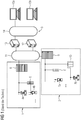
- FIG 2 a schematic diagram of a modular technical system 16 according to the invention is shown.
- the system 16 comprises a first, active module 17, a second, passive module 18 and a third, passive module 19.
- the three modules 17, 18, 19 are connected to a control system 20 of the modular technical system 16.
- the first, active module 17 comprises devices 21a, 21b to be controlled, an input / output system 22 and an active automation station 23.
- a first device 21a to be controlled is connected directly to the automation station 23 by means of Profibus®-DP (decentralized periphery).
- a second device 21b to be controlled is connected to the input / output system 22 via a HART connection (Highway Addressable Remote Transducer).
- the input / output system 22 can be, for example, a SIMATIC ET 200M from SIEMENS.
- the input / output system 22 is designed to transmit the data received from the second device 21b to be controlled to the automation station 23 via the Profibus connection (or to receive it in the opposite direction and to the second device 21b to be controlled) transfer). Since the first module 17 has its own automation station 23, this is referred to as an active module 17.
- the second module 18 comprises devices 24 to be controlled (only one of them is shown in FIG FIG 2 ) and an expanded input / output system 25.
- the module 18 has no automation station.
- the second module 18 requires the functionality of an additional automation or control device 26 located outside the second module 18. This is therefore referred to as a passive module 18.
- the third module 19 is constructed identically to the second module 18 and comprises devices 27 to be controlled (only one of which is in FIG 2 ) and also an expanded input / output system 28.
- the automation station 23 of the first, active module 17 and the additional automation or control device 26 are via a system bus 29 with an ES server (engineering station) 30 and an OS server 31 (operator station) of the control system 20 of the modular technical system 16 connected.
- the plant bus 11 can be, for example, Industrial Ethernet.
- the servers 30, 31 are connected to display and operating means 33a, 33b by means of a terminal bus 32.
- the process of coupling the passive modules 18, 19 with the active module 17 or with the control system 20 of the modular technical system 16 takes place in several steps: First, a communication link is established between the additional automation or control device 26 via Profibus® DP. The information required for the operation of the modules 18, 19 is then read from the extended input / output modules 25, 28. Finally, the information is integrated into automation of the additional automation or control device 26.
- the automation or control device 26 (referred to as "Automation System") of the control system 20 is controlled via the OS server 31.
- the automation or control device 26 reads an automation program 34 which is stored on the extended input / output modules 25, 28 of the two passive modules 18, 19.
- the automation program 34 is stored in the form of a CFC (Continuous Function Chart) and uses a certain number of automation types 35 (eg type "controller", type "valve” etc.).
- the automation program 34 additionally contains associated operating and monitoring descriptions (referred to as “passive package” 36) and interface information 37 (referred to as “interface description", for example with which data structure the passive modules 18, 19 must be addressed).
- the associated operating and observation descriptions 36 in turn comprise a certain number of system images 38 (referred to as “Operation Display Description").
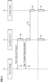
- FIG 4 an associated flowchart of the integration of the passive modules 18, 19 in the control system 20 of the modular technical system 16 is shown.
- a first step 39 the automation or control device 26 first loads the automation program 34 of the modules 18, 19.
- the automation program or its description (for example in the form of a CFC) is loaded into the automation or control device 26 integrated.
- the automation or control device 26 then loads the system images 38 from the modules 18, 19 in a third step 41 and transmits them to the OS server 31 of the control system 20 in a fourth step 42.
- a fifth step 43 the OS server 31 generates the necessary user interface during the runtime of the modular technical system.
- steps 44, 45 which run in parallel, the automation of the passive modules 18, 19 is carried out and the operating and monitoring station is operated on the OS server 31 in order to monitor the automation of the passive modules 18, 19.
- the pre-configured passive modules 18, 19 can be fully automatically integrated into the system 16 during the runtime of the modular technical system 16. This makes the flexibility of the system 16 clear increase. In addition, the time required for engineering the individual modules 18, 19 is reduced, since these can be configured autonomously by the other parts of the system 16.
Abstract
Vorgeschlagen wird ein Modul (18, 19) für eine modulare technische Anlage (16), insbesondere Prozessanlage, das wenigstens einen Aktor oder Sensor (24, 27) aufweist, und das eine Kommunikationsschnittstelle (25, 28) umfasst. Das Modul (18, 19) ist dadurch gekennzeichnet, dass das Modul (18, 19) keine Komponente zur Steuerung des wenigstens einen Aktors oder Sensors (24, 27) aufweist, und dadurch, dass in dem Modul (18, 19) Informationen hinterlegt sind, die es einer Vorrichtung (23, 26) außerhalb des Moduls (18, 19) ermöglichen, das Modul (18, 19) in der modularen technischen Anlage (16) zu betreiben.
Description
- Die Erfindung betrifft ein Modul für eine modulare technische Anlage nach Anspruch 1. Außerdem betrifft die Erfindung eine modulare technische Anlage nach Anspruch 5. Zudem betrifft die Erfindung ein Verfahren zur automatisierten Integration eines Moduls in eine modulare technische Anlage nach Anspruch 8 und die Verwendung eines Moduls zum Betrieb einer modularen technischen Anlage nach Anspruch 9.
- Bei verfahrenstechnischen Anlagen spielen Flexibilität und Skalierbarkeit eine immer größere Rolle. Dies führt auf der einen Seite dazu, dass Teile der Anlagen als kleine Einheiten separat entwickelt werden und dann in größere Anlagenteile integriert werden, um spezielle Produktionsschritte durchzuführen (Flexibilität). Auf der anderen Seite können einzelne Anlagenteile flexible zu einer größeren Anlage hinzugefügt werden, um Produktionssteigerungen zu erzielen (Skalierbarkeit).
- Aktuelle modulare Ansätze wie MTP (Modul Type Package) setzen für jede modulare Einheit eine eigene Automatisierung voraus. Je nach Größe der modularen Einheit kann es dabei zu einem unnötig hohen Vorhalten von Rechenleistung kommen. Zudem ist die Skalierbarkeit mit einem hohen Aufwand verbunden, da die einzelnen Module aufwändig in einem größeren Modulverbund zusammengefügt und projektiert werden müssen.
- Speziell bei sehr kompakten modularen Einheiten, die beispielsweise in der Pharmazie zum Einsatz kommen, stellen sich diese Nachteile als gewichtig dar. Modularisierungskonzepte wie MTP bedürfen vor einer Inbetriebnahme der Produktionsanlage Engineering-Schritten wie dem Auslesen bestimmter Schnittstellen und typisierter Anlagenbilder für die einzelnen Module. Zudem müssen händisch Anlagenbilder erstellt, Automatisierungsprogramme ausgesteuert und Prozessabbilder für die Bedienung und Beobachtung integriert werden. Zuletzt müssen die zuvor durchgeführten Schritte noch validiert werden. Die Projektierung der gesamten Produktionsanlage gestaltet sich dadurch aufwändig, zeitintensiv und fehlerbehaftet.
- In
FIG 1 ist exemplarisch die Integration eines ersten Produktionsmoduls 1 und eines zweiten Produktionsmoduls 2 in ein Leitsystem 3 einer Produktionsanlage 3 dargestellt. - Das erste Produktionsmodul 1 umfasst zu steuernde Geräte 4a, 4b, ein Input/Output-System 5 und eine aktive Automatisierungsstation 6. Ein erstes zu steuerndes Gerät 4a ist direkt mittels Profibus®-DP (dezentrale Peripherie) an die Automatisierungsstation 6 angeschlossen. Ein zweites zu steuerndes Gerät 4b ist über eine HART-Verbindung (Highway Addressable Remote Transducer) mit dem Input/Output System 5 verbunden. Das Input/Output System 5 kann beispielsweise eine SIMATIC ET 200M von SIEMENS sein. Das Input/Output System 5 ist dazu ausgebildet, die von dem zweiten zu steuernden Gerät 4b empfangenen Daten über die Profibus-Verbindung an die Automatisierungsstation 6 zu übertragen (bzw. in umgekehrter Richtung von dieser zu empfangen und an das zweite zu steuernde Gerät 4b zu übertragen).
- Die Automatisierungsstation 6 führt Steuerungs- und Regelungsfunktionen für das erste Produktionsmodul 1 aktiv durch. Sie umfasst in der Regel wenigstens eine Stromversorgung, eine zentrale Recheneinheit (CPU) und Kommunikationsbaugruppen. Es kann sich bei der Automatisierungsstation 6 beispielsweise um eine SIMATIC S7-400 von SIEMENS handeln.
- Das zweite Produktionsmodul 2 umfasst ebenfalls zu steuernde Geräte 7a, 7b, ein Input/Output-System 8 und eine aktive Automatisierungsstation 9. Im Gegensatz zu dem ersten Produktionsmodul 1 verfügt das zweite Gerät 7b über eine Profibus-PA (Prozess-Automation) Verbindung und benötigt daher ein Schnittstellenmodul 10, das eine Kommunikation zwischen der Profibus-PA und der Profibus-DP Verbindung ermöglicht.
- Die beiden Automatisierungsstationen 6, 9 sind über einen Anlagenbus 11 mit einem ES-Server (Engineering Station) 12 und einem OS-Server 13 (Operator Station) verbunden. Bei dem Anlagenbus 11 kann es sich beispielsweise um Industrial Ethernet handeln. Die Server 12, 13 sind mittels eines Terminalbusses 14 mit Anzeige- und Bedienmitteln 15a, 15b verbunden.
- Jedes Produktionsmodul 1, 2 weist gemäß dem bisherigen Verständnis eine eigene aktive Automatisierung 6, 9 auf. Nach außen hin stellen die Produktionsmodule 1, 2 "Black Boxes" dar, die in der Regel mittels einer MTP-Schnittstelle gekennzeichnet sind. Diese Schnittstelle muss jeweils durch ein entsprechendes Engineering in die gesamte Produktionsanlage integriert werden, was einen aufwändigen Prozess darstellt.
- Der Erfindung liegt die Aufgabe zugrunde, ein Modul für eine modulare technische Anlage anzugeben, das sich automatisiert und auf einfache Art und Weise in die Anlage integrieren lässt, ohne dabei übermäßig Ressourcen zu verbrauchen.
- Diese Aufgabe wird gelöst durch ein Modul für eine modulare technische Anlage nach Anspruch 1. Außerdem wird die Aufgabe gelöst durch eine modulare technische Anlage nach Anspruch 5. Zudem wird die Aufgabe gelöst durch ein Verfahren zur automatisierten Integration eines Moduls in eine modulare technische Anlage nach Anspruch 8 und die Verwendung eines Moduls zum Betrieb einer modularen technischen Anlage nach Anspruch 9. Vorteilhafte Weiterbildungen ergeben sich aus den abhängigen Ansprüchen.
- Ein erfindungsgemäßes Modul für eine modulare technische Anlage der eingangs beschriebenen Art, insbesondere Prozessanlage, weist wenigstens einen Aktor oder Sensor auf und verfügt über eine Kommunikationsschnittstelle.
- Das erfindungsgemäße Modul ist dadurch gekennzeichnet, dass das es keine Komponente zur Steuerung des wenigstens einen Aktors oder Sensors aufweist. Zudem ist es dadurch gekennzeichnet, dass in dem Modul Informationen hinterlegt sind, die es einer Vorrichtung außerhalb des Moduls ermöglichen, das Modul in der modularen technischen Anlage zu betreiben.
- Bei der modularen technischen Anlage kann es sich um eine Anlage aus der Prozessindustrie wie beispielsweise eine chemische, pharmazeutische, petrochemische oder eine Anlage aus der Nahrungs- und Genussmittelindustrie handeln. Hiermit umfasst sind auch jegliche Anlagen aus der Produktionsindustrie, Werke, in denen z.B. Autos oder Güter aller Art produziert werden. Technische Anlagen, die zur Durchführung des erfindungsgemäßen Verfahrens geeignet sind, können auch aus dem Bereich der Energieerzeugung kommen. Windräder, Solaranlagen oder Kraftwerke zur Energieerzeugung sind ebenso von dem Begriff der technischen Anlage umfasst.
- Diese Anlagen verfügen jeweils über ein Leitsystem oder zumindest ein computerunterstütztes Modul zur Steuerung und Regelung des ablaufenden Prozesses oder der Produktion. Teil des Leitsystems oder Steuerungsmoduls oder einer technischen Anlage ist in der Regel zumindest eine Datenbank oder ein Archiv, in dem historische Daten abgespeichert sind.
- Unter dem Begriff "Modul" wird eine Vorrichtung verstanden, die wenigstens einen Aktor oder Sensor aufweist. Zudem weist das Modul wenigstens eine Kommunikationsschnittstelle auf, die dazu dient, das Modul von außen zu steuern oder um innerhalb des Moduls generierte Daten nach außen zu übertragen. Die Kommunikation findet beispielsweise mit dem Leitsystem der modularen technischen Anlage oder mit anderen Modulen innerhalb der Anlage statt. Die Kommunikation kann aber auch in bzw. zu einer Cloudumgebung stattfinden. Unter einer Cloudumgebung wird dabei ein Rechnernetzwerk mit onlinebasierten Speicher- und Serverdiensten verstanden, welches üblicherweise auch als Cloud (engl. Wolke) oder Cloud-Plattform bezeichnet wird. Die in der Cloudumgebung gespeicherten Daten sind online zugänglich, sodass auch die modulare technische Anlage in der Regel über das Internet Zugriff auf ein zentrales Datenarchiv in der Cloud hat.
- Erfindungsgemäß weist das Modul keine Komponente zur Steuerung des wenigstens einen Aktors oder Sensors auf. Es handelt sich daher um ein rein passives Modul. Ohne die Verschaltung des Moduls mit einem anderen Modul oder mit dem Leitsystem der modularen technischen Anlage ist das erfindungsgemäße Modul nicht in der Lage, technische Aufgaben in der technischen Anlage zu erfüllen. Allerdings sind in dem Modul Informationen hinterlegt, die es einer Vorrichtung außerhalb des Moduls ermöglichen, das Modul in der modularen technischen Anlage zu betreiben. Eine solche Vorrichtung kann beispielsweise ein anderes (aktives) Modul oder ein Leitsystem mit einer entsprechenden Steuerungsarchitektur sein. Für einen Betrieb des Moduls wird in der Regel mindestens ein Automatisierungsprogramm und ein HMI (Human Machine Interface) benötigt.
- Mithilfe dieser Informationen (wenigstens Automatisierungsprogramm und HMI) lässt sich das Modul vollautomatisiert in die modulare technische Anlage integrieren.
- Dabei muss das erfindungsgemäße (passive) Modul vorteilhafterweise keine Rechenkapazitäten vorhalten. Auch ist eine Skalierbarkeit der modularen technischen Anlage durch die Verwendung eines oder mehrerer erfindungsgemäßer Module deutlich einfacher, da die (passiven) Module in einem "Plug & Play" Verfahren einfach zusätzlich in die modulare technische Anlage integriert werden können.
- Bevorzugt stellen die Informationen eine eindeutige Kennung des Moduls dar, mittels derer die Vorrichtung außerhalb des Moduls zusätzliche, zu einem Betrieb des Moduls benötigte Daten aus einer Datenbank außerhalb des Moduls entnehmen kann. Das passive Modul liefert dabei bei der Verbindung mit der modularen technischen Anlage eine eindeutige und unverwechselbare Identifizierung, die es der externen Vorrichtung (aktives Modul oder Leitsystem) ermöglicht, die Steuerungs- bzw. Automatisierungsaufgaben für das passive Modul vorzunehmen.
- Alternativ dazu können die in dem Modul hinterlegten Informationen alle zu einem Betrieb des Moduls benötigten Daten umfassen. Ein Vorteil dieser Weiterbildung des erfindungsgemäßen Moduls ist, dass keine separate Datenbank benötigt wird. Es kann beispielsweise vorkommen, dass die Datenbank nicht immer hundertprozentig verfügbar ist. Die Integration des passiven Moduls in die modulare technische Anlage würde sich dadurch unnötig verzögern bzw. erschwert sein.
- In beiden zuvor erläuterten Varianten können die zu einem Betrieb des Moduls benötigten Daten in Form eines Continuous Function Charts vorliegen, was die Integration des Moduls aufgrund der standardisierten Funktionsbeschreibungen des Moduls weiter vereinfacht.
- Die obige Aufgabe wird zudem gelöst durch eine modulare technische Anlage, die insbesondere eine Prozessanalage ist. Diese Anlage weist wenigstens ein (passives) Modul wie zuvor erläutert auf. Zudem weist die modulare technische Anlage wenigstens ein zweites Modul auf, das ebenfalls wenigstens einen Aktor oder Sensor aufweist und über eine Kommunikationsschnittstelle verfügt. Zusätzlich umfasst das zweite Modul eine Steuerungskomponente zur Steuerung des wenigstens einen Aktors oder Sensors, wobei in dem zweiten Modul Informationen hinterlegt sind, die es der Steuerungskomponente ermöglichen, das zweite Modul in der technischen Anlage zu betreiben.
- Mit anderen Worten wird umfasst die erfindungsgemäße modulare technische Anlage wenigstens eine zuvor erläutertes passives Modul und wenigstens ein aktives Modul.
- Vorteilhafterweise ist die Steuerungskomponente des zweiten Moduls dabei dazu ausgebildet und vorgesehen, mittels der in dem ersten Modul hinterlegten Informationen das erste Modul zu betreiben.
- Zusätzlich oder alternativ kann die Anlage eine Steuerungsvorrichtung außerhalb des wenigstens einen ersten Moduls und des wenigstens einen zweiten Moduls aufweisen, die dazu ausgebildet und vorgesehen ist, mittels der in dem ersten Modul hinterlegten Informationen das erste Modul zu betreiben.
- Die Aufgabe wird zudem gelöst durch ein Verfahren zur automatisierten Integration eines ersten zuvor erläuterten (passiven) Moduls in eine zuvor erläuterte modulare technische Anlage, die vorzugsweise eine Prozessanlage ist. Das Verfahren umfasst die folgenden Schritte:
- a) Herstellung einer Kommunikationsverbindung zwischen dem Modul und der Steuerungskomponente eines zweiten Moduls und/oder der Steuerungsvorrichtung der modularen technischen Anlage mittels der Kommunikationsschnittstelle des ersten Moduls.
- b) Auslesen der in dem ersten Modul hinterlegten Informationen, die es der Vorrichtung außerhalb des ersten Moduls ermöglichen, das erste Modul in der modularen technischen Anlage zu betreiben.
- c) Automatisierte Integration der ausgelesenen Informationen in die Steuerungskomponente des zweiten Moduls und/oder in die Steuerungsvorrichtung der modularen technischen Anlage.
- Im Zuge einer bevorzugten Verwendung kann das zuvor erläuterte Modul zum Betrieb einer modularen technischen Anlage, insbesondere Prozessanlage, eingesetzt sein.
- Die oben beschriebenen Eigenschaften, Merkmale und Vorteile dieser Erfindung sowie die Art und Weise, wie diese erreicht werden, werden klarer und deutlicher verständlich im Zusammenhang mit der folgenden Beschreibung des Ausführungsbeispiels, das im Zusammenhang mit den Zeichnungen näher erläutert wird. Es zeigen:
- FIG 2
- ein erfindungsgemäßes (passives) Modul in einer modulare technischen Anlage als Prinzipschaubild;
- FIG 3
- ein Objektmodell eines erfindungsgemäßen (passiven= Moduls; und
- FIG 4
- ein Ablaufdiagramm der Integration eines erfindungsgemäßen (passiven) Moduls in eine modulare technische Anlage.
- In
FIG 2 ist ein Prinzipschaubild einer erfindungsgemäßen modularen technischen Anlage 16 dargestellt. Die Anlage 16 umfasst ein erstes, aktives Modul 17, ein zweites, passives Modul 18 und ein drittes, passives Modul 19. Die drei Module 17, 18, 19 sind mit einem Leitsystem 20 der modularen technischen Anlage 16 verbunden. - Das erste, aktive Modul 17 umfasst zu steuernde Geräte 21a, 21b, ein Input/Output-System 22 und eine aktive Automatisierungsstation 23. Ein erstes zu steuerndes Gerät 21a ist direkt mittels Profibus®-DP (dezentrale Peripherie) an die Automatisierungsstation 23 angeschlossen. Ein zweites zu steuerndes Gerät 21b ist über eine HART-Verbindung (Highway Addressable Remote Transducer) mit dem Input/Output System 22 verbunden. Das Input/Output System 22 kann beispielsweise eine SIMATIC ET 200M von SIEMENS sein. Das Input/Output System 22 ist dazu ausgebildet, die von dem zweiten zu steuernden Gerät 21b empfangenen Daten über die Profibus-Verbindung an die Automatisierungsstation 23 zu übertragen (bzw. in umgekehrter Richtung von dieser zu empfangen und an das zweite zu steuernde Gerät 21b zu übertragen). Da das erste Modul 17 eine eigene Automatisierungsstation 23 aufweist, spricht man hier von einem aktiven Modul 17.
- Das zweite Modul 18 umfasst zu steuernde Geräte 24 (nur eines davon ist in
FIG 2 dargestellt) und ein erweitertes Input/Output-System 25. Das Modul 18 weist im Gegensatz zu dem ersten, aktiven Modul 17 keine Automatisierungsstation auf. Um das Gerät 24 bzw. dessen Aktoren und/oder Sensoren zu betreiben, benötigt das zweite Modul 18 die Funktionalität einer zusätzlichen, außerhalb des zweiten Moduls 18 befindlichen Automatisierungs- bzw. Steuerungsvorrichtung 26. Man spricht daher hier von einem passiven Modul 18. - In dem erweiterten Input/Output-System 25 sind Informationen hinterlegt, die alle zu einem Betrieb des zweiten Moduls 18 benötigten Daten umfassen. Für nähere Informationen hierzu sei auf die Beschreibung der
Figuren 3 und4 verwiesen. - Das dritte Modul 19 ist baugleich zu dem zweiten Modul 18 aufgebaut und umfasst zu steuernde Geräte 27 (nur eines davon ist in
FIG 2 dargestellt) und ebenfalls ein erweitertes Input/Output-System 28. - Die Automatisierungsstation 23 des ersten, aktiven Moduls 17 und die zusätzliche Automatisierungs- bzw. Steuerungsvorrichtung 26 sind über einen Anlagenbus 29 mit einem ES-Server (Engineering Station) 30 und einem OS-Server 31 (Operator Station) des Leitsystems 20 der modularen technischen Anlage 16 verbunden. Bei dem Anlagenbus 11 kann es sich beispielsweise um Industrial Ethernet handeln. Die Server 30, 31 sind mittels eines Terminalbusses 32 mit Anzeige- und Bedienmitteln 33a, 33b verbunden.
- Der Ablauf einer Kopplung der passiven Module 18, 19 mit dem aktiven Modul 17 bzw. mit dem Leitsystem 20 der modularen technischen Anlage 16 erfolgt in mehreren Schritten: Zunächst wird über Profibus® DP eine Kommunikationsverbindung zwischen der zusätzlichen Automatisierungs- bzw. Steuerungsvorrichtung 26 hergestellt. Daran anschließend wird werden die für den Betrieb der Module 18, 19 benötigten Informationen aus den erweiterten Input/Output-Modulen 25, 28 gelesen. Schließlich werden die Informationen in eine Automatisierung der zusätzlichen Automatisierungs- bzw. Steuerungsvorrichtung 26 integriert.
- Die Automatisierungs- bzw. Steuerungsvorrichtung 26 (als "Automation System" bezeichnet) des Leitsystems 20 wird über den OS-Server 31 gesteuert. Die Automatisierungs- bzw. Steuerungsvorrichtung 26 liest ein Automatisierungsprogramm 34, das auf den erweiterten Input/Output-Modulen 25, 28 der beiden passiven Module 18, 19 hinterlegt ist. Das Automatisierungsprogramm 34 ist in Form eines CFC (Continuous Function Chart) hinterlegt und nutzt eine bestimmte Anzahl von Automatisierungstypen 35 (z.B. Typ "Regler", Typ "Ventil" etc.).
- Das Automatisierungsprogramm 34 beinhaltet zusätzlich dazugehörige Bedien- und Beobachtungsbeschreibungen (als "Passive Package" 36 bezeichnet) sowie Schnittstelleninformationen 37 (als "Interface Description" bezeichnet, z.B. mit welcher Datenstruktur die passiven Module 18, 19 angesprochen werden müssen). Die dazugehörigen Bedien- und Beobachtungsbeschreibungen 36 umfassen wiederum eine bestimmte Anzahl an Anlagenbildern 38 (als "Operation Display Description" bezeichnet).
- In
FIG 4 ein dazugehöriges Ablaufdiagramm der Integration der passiven Module 18, 19 in das Leitsystem 20 der modularen technischen Anlage 16 dargestellt. - Die Automatisierungs- bzw. Steuerungsvorrichtung 26 lädt in einem ersten Schritt 39 zunächst das Automatisierungsprogramm 34 der Module 18, 19. In einem zweiten Schritt 40 wird das Automatisierungsprogramm bzw. dessen Beschreibung (z.B. in Form eines CFC) in die Automatisierungs- bzw. Steuerungsvorrichtung 26 integriert. Darauf lädt die Automatisierungs- bzw. Steuerungsvorrichtung 26 lädt in einem dritten Schritt 41 die Anlagenbilder 38 aus den Modulen 18, 19 und übermittelt diese in einem vierten Schritt 42 an den OS-Server 31 des Leitsystems 20.
- In einem fünften Schritt 43 erzeugt der OS-Server 31 zur Laufzeit der modularen technischen Anlage die notwendige Benutzeroberfläche. In parallel ablaufenden Schritten 44, 45 werden die Automatisierung der passiven Module 18, 19 durchgeführt und die Bedien- und Beobachtungsstation auf dem OS-Server 31 betrieben, um die Automatisierung der passiven Module 18, 19 zu überwachen.
- Als Resultat lassen sich die vorprojektierten passiven Module 18, 19 zur Laufzeit der modularen technischen Anlage 16 vollautomatisiert in die Anlage 16 integrieren. Dadurch lässt sich die Flexibilität der Anlage 16 deutlich erhöhen. Zudem verringert sich der Zeitaufwand für ein Engineering der einzelnen Module 18, 19, da diese autark von den übrigen Teilen der Anlage 16 projektiert werden können.
- Obwohl die Erfindung im Detail durch das bevorzugte Ausführungsbeispiel näher illustriert und beschrieben wurde, so ist die Erfindung nicht auf das offenbarte Beispiel eingeschränkt und andere Variationen können vom Fachmann hieraus abgeleitet werden, ohne den Schutzumfang der Erfindung zu verlassen.
Claims (9)
- Modul (18, 19) für eine modulare technische Anlage (16), insbesondere Prozessanlage, das wenigstens einen Aktor oder Sensor (24, 27) aufweist, und das eine Kommunikationsschnittstelle (25, 28) umfasst,
dadurch gekennzeichnet, dass
das Modul (18, 19) keine Komponente zur Steuerung des wenigstens einen Aktors oder Sensors (24, 27) aufweist, und dass in dem Modul (18, 19) Informationen hinterlegt sind, die es einer Vorrichtung (23, 26) außerhalb des Moduls (18, 19) ermöglichen, das Modul (18, 19) in der modularen technischen Anlage (16) zu betreiben. - Modul (18, 19) nach Anspruch 1, bei dem die Informationen eine eindeutige Kennung des Moduls (18, 19) darstellen, mittels derer die Vorrichtung (23, 26) außerhalb des Moduls (18, 19) zusätzliche, zu einem Betrieb des Moduls (18, 19) benötigte Daten aus einer Datenbank außerhalb des Moduls (18, 19) entnehmen kann.
- Modul (18, 19) nach Anspruch 1, bei dem die in dem Modul (18, 19) hinterlegten Informationen alle zu einem Betrieb des Moduls (18, 19) benötigten Daten umfassen.
- Modul (18, 19) nach Anspruch 2 oder 3, bei dem die zu einem Betrieb des Moduls (18, 19) benötigten Daten in Form eines Continuous Function Charts vorliegen.
- Modulare technische Anlage (16), insbesondere Prozessanalage, mit wenigstens einem ersten Modul (18, 19) gemäß einem der Ansprüche 1 bis 4,
und wenigstens einem zweiten Modul (1, 2, 17), das wenigstens einen Aktor oder Sensor (4a, 4b, 7a, 7b, 21a, 21b) aufweist, und das eine Kommunikationsschnittstelle (5, 10, 22) umfasst,
und das eine Steuerungskomponente (6, 9, 23, 26) zur Steuerung des wenigstens einen Aktors oder Sensors (4a, 4b, 7a, 7b, 21a, 21b) aufweist, wobei in dem zweiten Modul (1, 2, 17) Informationen hinterlegt sind, die es der Steuerungskomponente (6, 9, 23, 26) ermöglichen, das zweite Modul (1, 2, 17) in der technischen Anlage (16) zu betreiben. - Modulare technische Anlage (16) nach Anspruch 5, bei der die Steuerungskomponente (6, 9, 23) des zweiten Moduls (1, 2, 17) dazu ausgebildet und vorgesehen ist, mittels der in dem ersten Modul (18, 19) hinterlegten Informationen das erste Modul (18, 19) zu betreiben.
- Modulare technische Anlage (16) nach Anspruch 5 oder 6, bei der die Anlage (16) eine Steuerungsvorrichtung (26) außerhalb des wenigstens einen ersten Moduls (18, 19) und des wenigstens einen zweiten Moduls (1, 2, 17) aufweist, die dazu ausgebildet und vorgesehen ist, mittels der in dem ersten Modul (18, 19) hinterlegten Informationen das erste Modul (18, 19) zu betreiben.
- Verfahren zur automatisierten Integration eines ersten Moduls (18, 19) gemäß einem der Ansprüche 1 bis 4 in eine modulare technische Anlage (16) nach einem der Ansprüche 5 bis 7, vorzugsweise Prozessanlage, umfassend:a) Herstellung einer Kommunikationsverbindung zwischen dem ersten Modul (18, 19) und der Steuerungskomponente (6, 9, 23) eines zweiten Moduls (1, 2, 17) und/oder der Steuerungsvorrichtung (26) der modularen technischen Anlage (16) mittels der Kommunikationsschnittstelle (5, 10, 22) des ersten Moduls (18, 19);b) Auslesen der in dem ersten Modul (18, 19) hinterlegten Informationen, die es einer Vorrichtung (6, 9, 23, 26) außerhalb des ersten Moduls (18, 19) ermöglichen, das erste Modul (18, 19) in der modularen technischen Anlage (16) zu betreiben;c) Automatisierte Integration der ausgelesenen Informationen in die Steuerungskomponente (6, 9, 23) des zweiten Moduls (1, 2, 17) und/oder in die Steuerungsvorrichtung (26) der modularen technischen Anlage (16) .
- Verwendung eines Moduls (18, 19)) gemäß einem der Ansprüche 1 bis 4 zum Betrieb einer modularen technischen Anlage (16), insbesondere Prozessanlage.
Priority Applications (1)
| Application Number | Priority Date | Filing Date | Title |
|---|---|---|---|
| EP18184975.3A EP3599524A1 (de) | 2018-07-23 | 2018-07-23 | Modulare technische anlage |
Applications Claiming Priority (1)
| Application Number | Priority Date | Filing Date | Title |
|---|---|---|---|
| EP18184975.3A EP3599524A1 (de) | 2018-07-23 | 2018-07-23 | Modulare technische anlage |
Publications (1)
| Publication Number | Publication Date |
|---|---|
| EP3599524A1 true EP3599524A1 (de) | 2020-01-29 |
Family
ID=63035920
Family Applications (1)
| Application Number | Title | Priority Date | Filing Date |
|---|---|---|---|
| EP18184975.3A Withdrawn EP3599524A1 (de) | 2018-07-23 | 2018-07-23 | Modulare technische anlage |
Country Status (1)
| Country | Link |
|---|---|
| EP (1) | EP3599524A1 (de) |
Citations (4)
| Publication number | Priority date | Publication date | Assignee | Title |
|---|---|---|---|---|
| US5901323A (en) * | 1990-12-11 | 1999-05-04 | Fisher Controls International, Inc. | Process controller with interchangeable individual I/O units |
| DE10208530A1 (de) * | 2002-02-27 | 2003-09-18 | Moeller Gmbh | Betriebseinheit, Peripheriegerät und Verfahren zum Betrieb eines Peripheriegeräts |
| EP2801880A2 (de) * | 2013-05-10 | 2014-11-12 | Rolls-Royce plc | Geräteüberwachungssystem |
| EP3021179A1 (de) * | 2014-11-14 | 2016-05-18 | Schneider Electric Automation GmbH | Verfahren zum anschliessen eines embedded-geräts an eine steuereinheit |
-
2018
- 2018-07-23 EP EP18184975.3A patent/EP3599524A1/de not_active Withdrawn
Patent Citations (4)
| Publication number | Priority date | Publication date | Assignee | Title |
|---|---|---|---|---|
| US5901323A (en) * | 1990-12-11 | 1999-05-04 | Fisher Controls International, Inc. | Process controller with interchangeable individual I/O units |
| DE10208530A1 (de) * | 2002-02-27 | 2003-09-18 | Moeller Gmbh | Betriebseinheit, Peripheriegerät und Verfahren zum Betrieb eines Peripheriegeräts |
| EP2801880A2 (de) * | 2013-05-10 | 2014-11-12 | Rolls-Royce plc | Geräteüberwachungssystem |
| EP3021179A1 (de) * | 2014-11-14 | 2016-05-18 | Schneider Electric Automation GmbH | Verfahren zum anschliessen eines embedded-geräts an eine steuereinheit |
Non-Patent Citations (1)
| Title |
|---|
| WAGO: "DIMA - Dezentrale Intelligenz für modulare Anlagen", 14 December 2015 (2015-12-14), pages 1 - 8, XP055355896, Retrieved from the Internet <URL:http://www.dima-process.com/wp-content/uploads/2015/12/WHITEPAPER_Technische_Loesung_fuer_die_Automatisierung_modularer_Anlagen.pdf> [retrieved on 20170317] * |
Similar Documents
| Publication | Publication Date | Title |
|---|---|---|
| EP2789145B1 (de) | Vorrichtung zur bedienung von mindestens einem feldgerät der automatisierungstechnik | |
| EP1096348B1 (de) | Integration eines Feldleitgerätes in ein Anlagenleitsystem | |
| DE102010029952A1 (de) | Verfahren zum Integrieren von zumindest einem Feldgerät in ein Netzwerk der Automatisierungstechnik | |
| DE102010062266A1 (de) | Verfahren zur Realisierung von zumindest einer Zusatzfunktion eines Feldgeräts in der Automatisierungstechnik | |
| EP3876046A1 (de) | Rückannotation von operatorselektionen | |
| EP3623891A1 (de) | Individualisierbare bildhierarchien für ein leitsystem einer technischen anlage | |
| EP3637205A1 (de) | Bildaufschaltung auf einem operator station client | |
| WO2016141998A1 (de) | Vorrichtung und verfahren zum bereitstellen einer digitalen abbildung einer physikalischen entität | |
| DE102007059671A1 (de) | Verfahren zum Betreiben eines Systems aufweisend ein Feldgerät und ein Bediensystem | |
| DE102011005062A1 (de) | Verfahren zum Bereitstellen von Daten eines Feldgeräts | |
| EP3650970A1 (de) | Verfahren und vorrichtung zum computergestützten simulieren eines modularen technischen systems | |
| EP3861413B1 (de) | Verfahren zum etablieren einer netzwerkkommunikation mittels opc ua | |
| EP1758001A2 (de) | Verfahren und System zum Abbilden der Struktur einer Automatisierungsanlage auf einem Rechner | |
| EP3652595B1 (de) | Verfahren und system zum überwachen einer anlage der automatisierungstechnik | |
| EP2557464A1 (de) | Verfahren zum Betrieb eines Automatisierungssystems | |
| EP3599524A1 (de) | Modulare technische anlage | |
| EP1454201B1 (de) | Engineeringsystem und automatisierungssystem | |
| WO2008077358A1 (de) | Geräteverbund mit einem automatisierungsgerät und einem bediengerät sowie verfahren zum betrieb eines solchen geräteverbunds | |
| DE102007062398A1 (de) | Verfahren und Vorrichtung zur Integration eines Feldgeräts der Automatisierungstechnik in beliebige übergeordnete Steuerstrukturen | |
| DE102018131119A1 (de) | Integration mehrerer Anlagenmodule mit jeweils wenigstens einer prozesstechnischen Einheit zu einer modular aufgebauten Gesamtanlage | |
| LU500646B1 (de) | Technik zur Bereitstellung einer Diagnosefunktionalität für eine auf einer speicherprogrammierbaren Steuerung basierenden Anwendung | |
| DE102016121788A1 (de) | Konfiguration einer Automatisierungsanlage | |
| EP4124917A1 (de) | Steuerbare verbindung zwischen datenquellen und datensenken bei einer automatisierungslösung | |
| DE202021106310U1 (de) | Computerimplementiertes Prozessmodul | |
| DE102022204494A1 (de) | Datenverarbeitungssystem zur effizienten Kommunikation großer Datenmengen |
Legal Events
| Date | Code | Title | Description |
|---|---|---|---|
| PUAI | Public reference made under article 153(3) epc to a published international application that has entered the european phase |
Free format text: ORIGINAL CODE: 0009012 |
|
| AK | Designated contracting states |
Kind code of ref document: A1 Designated state(s): AL AT BE BG CH CY CZ DE DK EE ES FI FR GB GR HR HU IE IS IT LI LT LU LV MC MK MT NL NO PL PT RO RS SE SI SK SM TR |
|
| AX | Request for extension of the european patent |
Extension state: BA ME |
|
| STAA | Information on the status of an ep patent application or granted ep patent |
Free format text: STATUS: THE APPLICATION IS DEEMED TO BE WITHDRAWN |
|
| 18D | Application deemed to be withdrawn |
Effective date: 20200730 |